1
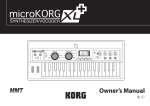
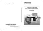
1
2
3
4
5
GSC-3
6
7
8
10
9
12
13
14
11
GSC-3
15
16
17
12
13
14
11
GSC-2
15
16
17
Version 2.5
Table of contents
IMPORTANT SAFETY INSTRUCTIONS
2
FCC COMPLIANCE
2
DECLARATION OF CONFORMITY
2
PACKAGE CONTENT
3
STRUCTURE
4
SIGNAL’S PATH DIAGRAM
5
BANKS, PRESETS AND MODIFIERS
5
PRESET SELECTION
6
BANK SELECTION
6
SILENT TUNING (MUTE)
6
PRESET PROGRAMMING
7
LOOPS (LOOP1 TO LOOP6) PROGRAMMING
7
AMP SETTINGS PROGRAMMING
7
MIDI PROGRAM NUMBERS PROGRAMMING
7
PRESET’S COPYING
8
BANK COPYING
8
CC CONTROLLERS’ VALUE PROGRAMMING
8
SENDING ADDITIONAL PROGRAM CHANGE COMMANDS
9
MODIFIERS PROGRAMMING
9
TAP TEMPO
9
SILENT SWITCHING FUNCTION
9
SETTINGS
10
LOOP BUTTON SETTINGS
10
SWITCH BUTTON SETTINGS
11
MIDI CHANNELS SETTING
12
AMP CONTROLLING
12
G LAB WP WAH-PAD CONNECTING
13
G LAB TBWP TRUE BYPASS WAH-PAD CONNECTING
13
CONNECTING AUX BANK UP/DOWN WITH MIDI IN FOOTSWITCH
13
USB CONNECTING WITH PC
13
AUX CONNECTOR
13
MIDI 4 X LOOP-ER CONNECTING
14
TECHNICAL PARAMETERS
14
MIDI IMPLEMENTATION CHART
15
1
Important safety instructions
–
–
–
–
–
–
–
–
–
–
Read these instructions and follow them.
Prevent this device against moisture or spilling liquid inside.
Clean only with dry cloth.
Do not install near any heat sources such as radiators, heat registers, stoves, or other apparatus
producing a lot of heat
Protect the power supply cord from being walked on or pinched.
Only use attachments/accessories specified by the manufacturer.
Unplug this device during lighting storms or when unused for long periods of time.
Do no open device or its power supply casing.
The power supply adapter should be installed in the socket outlet and disconnection of the adapter
should be easily accessible.
To completely disconnect from AC mains disconnect the power supply adapter from the AC receptacle.
FCC Compliance
This device complies with Part 15 of the FCC Rules. Operation is subject to the following two conditions: (1)
this device may not cause harmful interference, and (2) this device must accept any interference received,
including interference that may cause undesired operation.
NOTE: This equipment has been tested and found to comply with the limits for a Class B digital device,
pursuant to Part 15 of the FCC Rules. These limits are designed to provide reasonable protection against
harmful interference in a residential installation. This equipment generates, uses and can radiate radio
frequency energy and, if not installed and used in accordance with the instructions, may cause harmful
interference to radio communications. However, there is no guarantee that interference will not occur in
a particular installation.
If this equipment does cause harmful interference to radio or television reception, which can be determined
by turning the equipment off and on, the user is encouraged to try to correct the interference by one or
more of the following measures:
–
–
–
–
Reorient or relocate the receiving antenna.
Increase the separation between the equipment and receiver.
Connect the equipment into an outlet on a circuit different from that to which the receiver is connected.
Consult the dealer for help.
Declaration of Conformity
Elzab Soft Sp. z o.o., ul. Kruczkowskiego 39, 41-813 Zabrze, Poland,
declare under sole responsibility, that the following product:
G LAB/GSC-3, GSC-2 – Guitar System Controller
conforms with requirements of the EC Council Directives:
● 2006/95/EEC Low Voltage Directive,
● 2004/108/EEC Electromagnetic Compatibility,
and holds CE mark. Above named product conforms with the following standards:
● PN-EN 60065:2004 /EN 60065:2002/ Audio, video and similar apparatus - Safety requirements.
● PN-EN 55103-1:2000 /EN 55103-1:1996/ Electromagnetic compatibility - Product family standard for
audio, video, audio-visual and entertainment lighting control apparatus for professional use - Part 1:
Emission
● PN-EN 55103-2:2001 /EN 55103-2:1996/ Electromagnetic compatibility - Product family standard for
audio, video, audio-visual and entertainment lighting control apparatus for professional use - Part 2:
Immunity
Arkadiusz Kocik
President of the Elzab Soft Sp. z o.o. Board of Directors
Copy of original EC declaration of conformity is available for download on our website
http://www.glab.com.pl
2
Dear Customer,
Congratulations for choosing our G LAB product!
Guitar System Controller (GSC) is the programmable switching device of effects’ loops (looper), the amp’s
switcher by footswitch input and the MIDI devices’ controller in one. By pressing just a single footswitch
(called preset) it enables:
– to activate selected effects (connected to LOOP1 up to LOOP6 loops),
– to set the amp channel (or the pre-amp one) and other amp’s functions controlled by its footswitch
input,
– to set by Program Change command the MIDI device’s program No. of work (at three MIDI devices
e.g. effects’ processors).
The presets are stored in 10 banks. Depending on the method of changing the banks there are available
eight or ten presets in each bank. Controller posses presets programming function and presets and banks
copying functions what enables quick “organising” of the presets in the banks. The GSC enables also to
assign to its footswitches following functions instead of presets:
– to switch on/off the loop (loop modifier),
– to set the amp settings function (e.g. selecting a channel),
– to select the program No. (or numbers) of MIDI device (devices).
To avoid the incidental changing of the presets’ settings the controller is equipped with the memory access lock.
There are available two versions of the controller with different footswitches. The GSC-3 model posses metal
footswitches with backligthed descriptions and the GSC-2 model posses silent, backlighted footswitches.
Basic characteristics:
– true passive signal path (except buffer),
– true bypassed (by relay), high impedance input buffer,
– TUNER output with the silent tuning function based on very high impedance circuit (no influence on
a guitar signal),
– six TRUE BYPASS loops for connecting effects (using electro-mechanical relays),
– six 9V DC outputs (for supplying effects) in two separated sections (500mA each),
– 2 outputs (2 lines each, latching type) for controlling the amp through its footswitch input,
– MIDI output for controlling MIDI devices by Program Change and Control Change commands,
– AUX connector for connecting extension modules,
– USB connector for connecting to a PC, enabling downloading, editing and saving presets and
settings, also firmware upgrades,
– two modes of bank selection (by BANK UP / BANK DOWN footswitches or by pressing and holding
presets’ footswitches) and an option “one bank mode”,
– input for connecting a wah-wah effect pad (wah-pad) to control the system by placing the foot on
the wah-wah,
– external power supply with 4 meters long and flexible cable
Package content
Controller
Power supply adapter
Three 9V 40 cm cables
Two 9V 80 cm cables
One 9V 120 cm cables
User’s Manual
3
Structure
On the inner side of the instruction cover are placed the pictures with elements numerated below.
1 - IN – guitar signal input
2 - TUNER – guitar tuner connector
3 - OUT – amp’s signal output connector
4 - SEND – effect’s loop output connector
5 - RETURN – effect’s loop input connector
6 - OUT SW1&2 and SW3&4 – output connectors for amp's switching by its footswitch input
7 - WAH-PAD – wah-pad connector
8 - MIDI OUT – MID output connector
9 - POWER 12V DC – 12V DC power supply connector
10 - OUT 9V DC – Effects’ power supply connectors
11 - Presets selecting footswitches
12 - Indicators
13 - Display
14 - Programming buttons
15 - AUX connector
16 - Memory access lock switch
17 - USB connector
BUFFER – Buffer indicator
LOOP 1 to 6 – Indicators signalising switching on LOOPs
POWER FAIL – Voltage failure indicator (voltage below 11.2V or above 12,8V)
SWITCH 1 to 4 – SW1 to SW4 switch outputs’ status indicators
LOCK – Memory access LOCK indicator
LOOP – loops programming button and indicator
SWITCH – amp’s controlling outputs button and indicator
MIDI 1 – button and indicator for editing MIDI program of MIDI 1 device
MIDI 2 – button and indicator for editing MIDI program of MIDI 2 device
4
Signal’s path diagram
Guitar signal, thru very high impedance (>10 MΩ) tuner buffer, is transmitted to TUNER output. It enables
using of the tuner during playing.
Controller features a switchable, true bypass input buffer circuit. Buffer which’s input impedance is consistent
with tube amps boost the guitar signal power (without the voltage increase).
Adding the buffor between the guitar and the effect can improve guitar sound (due to low input impedance
many of the effects change the guitar tone) and in case of using long cables (between the controller and
the amp) it enables to avoid high tones loss caused by cables’ parasitic capacitance appearing when all
the effects are switched off.
SEND outputs should be connected with IN effects inputs and RETURN inputs should be connected with
OUT outputs of particular effects. MUTE block silents the signal during the quiet tunning.
Controller has six 9V DC outputs for supplying the effects in two fully separated sections (500mA each).
Before plugging the power supply the pin polarization coincidence should be checked.
Banks, presets and modifiers
Controller enables to program 10 presets (or 8 ones) in each of its 10 banks. There is information on the
display about the bank and preset numbers. Banks and presets have got numbers from 0 to 9 range.
bank number 2
preset mode
preset number 3
The P character in front of double dot says that the given footswitch in the given bank is a preset. The L
character says that the given footswitch is a loop modifier (similarly S character for a SWITCH modifier and
n character for a MIDI modifier). The loop modifier switches on and off the selected effects’ loop. The
SWITCH modifier sets the amp’s channel. The MIDI modifier sends the Program Change and/or Control
Change MIDI commands to selected MIDI devices. Such solution enables to program banks only with
presets to switch all the system just by pressing a single footswitch and to program the banks where
5
particular footswitches perform the selected functions e.g. to switch on the single effect, to set the amps
channel. Also it is possible to program some banks where a part of footswitches are presets and the other
are modifiers.
Below you will find the example of using presets and modifiers.
Preset selection
Press shortly (less then 1 second) the preset footswitch numbered from 1 to 5 (in the cb1 mode banks
change from 0 to 9; in the cb2 mode banks change from 1 to 4 or from 6 to 9).
Bank selection
At the cb1 mode (pressing and holding preset footswitch).
Press and hold (more then 1 second) the desired preset footswitch numbered from 0 to 9.
During switching there will be activated for 1 second the preset adequate to the previously selected bank.
Choosing this method enables to use 10 presets in each bank. It is recommended to organise presets in
banks in such a way that all necessary presets used in a particular song will be located into just one bank.
At the cb2 mode (using BANK UP / BANK DOWN buttons).
Select the bank number using BANK UP (footswitch 0) or BANK DOWN (footswitch 5) and then press the
preset footswitch (from range 1 to 4 or 6 to 9).
Till the moment the preset footswitch is pressed the previous preset is active. It enables switching presets
from the different banks while a song is played.
Choosing this method enables to use 8 presets in each bank.
To escape from the bank selecting function press and hold 0 or 5 footswitch longer then 1 second.
At the cb3 mode (directly by using BANK UP/BANK DOWN footswitches for firmware 2.20 and higher).
At this mode BANK UP and BANK DOWN footswitches cause correspondingly lowering and increasing
bank number with immediate preset recalling (preset number in bank remains unchanged).
Silent tuning (MUTE)
Press simultaneously the footswitch No. 1 and 2 (blinking tun text will appear on the display).
To exit from MUTE press the preset footswitch intended to be used.
It is possible to define the footswitch No. 6 as a footswitch activating silent tuning mode MUTE (see Loop
button settings, footswitch No. 7).
6
Preset programming
A preset is defined by:
– switched on effects (connected to LOOP1 to LOOP6) and buffer switched on or off;
– amp’s setting (amp channel and/or effect selecting) controlled by SW1 to SW4 outputs;
– MIDI Program Change numbers (and Control Change commands) transmitted to MIDI devices.
Loops (LOOP1 to LOOP6) programming
a) Select bank and preset.
b) Memory access lock switch to UNLOCK position (LOCK indicator not lit).
c) Press LOOP button (LOOP indicator and preset number start to blink).
d) Check if P character is displayed before the double dot. If not set it by footswitch No. 7 (PRESET
MODE)
e) By presets footswitches 1 to 5 and 0 set loops (effects) which should be active (indicators LOOP 1
to 6 lit mean effects are activated). Switch on/off the buffer by footswitch No. 6 (BUFFER indicator
lit means the buffer is active).
f) Press LOOP button to save. Displaying text Stored confirm saving.
In case of necessity of escape without saving while the point d) or e) it should be pressed SWITCH or
MIDI 1 or MIDI 2 button.
REMARK:
In case of not plugging in a connector to a particular effect’s loop RETURN the signal will skip such a loop
despite of activating this loop. It allows to use presets despite of not connecting effects to such a loop.
Amp settings programming
a) Select bank and preset.
b) Memory access lock switch to UNLOCK position (LOCK indicator not lit).
c) Press SWITCH button (SWITCH indicator and preset number start to blink).
d) By footswitches 1 to 4 set SWITCH outputs (SW1 to SW4 indicators signalise amp settings).
e) Press SWITCH button to save. Displaying text Stored confirm saving.
In case of necessity of escape without saving while the point d) it should be pressed LOOP or MIDI 1 or
MIDI 2 button.
MIDI program numbers programming
The controller enables to control three MIDI devices (MIDI 1, MIDI 2 and MIDI 3) by the Program Change
command. Before programming, the MIDI channels should be set (see: MIDI channel setting).
a) Connect MIDI cable between MIDI OUT output connector and MIDI IN input connector of the
controlled device.
b) Select bank and preset.
c) Memory access lock switch to UNLOCK position (LOCK indicator not lit).
d) Press MIDI 1 button (MIDI 1 indicator will start to blink). Actual program No. or text unused (what
means that command is not send) will appear on display.
e) Enter program No. using footswitches (e.g. for program No. 24 press footswitch No. 2 and then
footswitch No. 4). If you don’t want to send Program Change command in this preset press
footswitch No. 0 and hold for minimum 1 second (text unu will appear on display).
Available program numbers are from 1 to 128 (transmitted values from 0 to 127). The text Err
means the number is out of the range.
f) Press MIDI 1 button to save. Displaying text Stored confirms saving.
In case of necessity of escape without saving while the point e) it should be pressed LOOP or SWITCH
button.
7
For MIDI 2 device do it in similar way and for MIDI 3 device the MIDI 1 and MIDI 2 buttons should be pressed
simultaneously. The MIDI 3 program number can be programmed in this way only when the setting at LOOP
button (No. 6 footswitch) is set to n3p (MIDI 3, only Program Change command).
Preset’s copying
a) Select preset to copy.
b) Memory access lock switch to UNLOCK position (LOCK indicator not lit).
c) Press at simultaneously LOOP and MIDI 2 buttons (LOOP and MIDI 2 indicators start to blink and
SWITCH and MIDI 1 indicators start to lit).
d) Switch bank (if necessary) and choose preset No. where to past copied preset.
e) Press simultaneously LOOP and MIDI 2 buttons to save preset. Text Stored confirms saving.
In case of necessity of escaping without saving while in the point d) should be pressed SWITCH or MIDI 1
button.
Bank copying
a) Select any preset of the bank to copy.
b) Memory access lock switch to UNLOCK position (LOCK indicator not lit).
c) Press simultaneously SWITCH and MIDI 1 buttons (SWITCH and MIDI 1 indicators start to blink
and LOOP and MIDI 2 indicators start to lit).
d) Choose a bank where to past copied bank.
e) Press simultaneously SWITCH and MIDI 1 buttons to save bank. Text Stored confirms saving.
In case of necessity of escaping without saving while in the point d) should be pressed LOOP or MIDI 2
button.
CC controllers’ value programming
The GSC enables to control MIDI 3 device by Control Change commands. Before value programming at
LOOP button settings (footswitch No. 6) set transmitting Control Change commands (m3c), and set
controllers’ numbers (see: Controllers’ numbers setting for Control Change commands).
a) Select bank and preset.
b) Memory access lock switch to UNLOCK position (LOCK indicator not lit).
c) Press simultaneously MIDI 1 and MIDI 2 buttons (MIDI 1 and MIDI 2 indicators start to blink).
The text ctl will appear on display.
d) Short pressing footswitches numbered from 1 to 7 will effect in short displaying text CC and the controllers No. e.g. 81 and after actual value of the controller will be displayed. Pressing No. 0 footswitch
displays the actual program No. transmitted to the MIDI 3 device by Program Change command.
e) Press and hold for longer than 1 second the controller footswitch intended to be changed (blinking
“0” will appear on display).
f) Enter the value of controller using footswitches. The controller value can be from 0 to 127 range,
unused or toggle. Press and hold for longer than 1 second footswitch No. 0 to set the controller
unused (not to be transmitted). To set the toggle function press and hold for longer than 1 second
the footswitch No. 5. Toggle function means that successive pressing the footswitch toggles transmitted values 0 and 127 and effects in switching on/off a chosen parameter or a function of MIDI 3
device. In case when we programmed the footswitch as a MIDI modifier and the only transmitted
command is toggle value controller we get the footswitch e.g. switching on and off a single effect at
multieffect device. In this way we get the functionality of such a footswitch identical with loop
modifier (for a single effect as stompbox connected to a loop). When at other preset or modifier the
given controller is transmitted with value 0 or 127 the toggle function will consider the previously
transmitted value.
g) Press MIDI 1 (or MIDI 2) button to accept the value. If you want to edit the value of other controller
operate according to point d) and e).
8
h) Press simultaneously MIDI 1 and MIDI 2 buttons to save entered vales. Text Stored confirms saving.
In case of necessity of escaping without saving while in the point d) should be pressed LOOP or
SWITCH button.
Sending additional Program Change commands
Controller enables sending out four additional Program Change commands (named PC4 to PC7) instead
of Control Change 4 to 7 commands. To use this option it is needed:
– to set at LOOP button settings (footswitch No. 6) transmitting three Control Change and five
Program Change (m3A) commands,
– to set at SWITCH button settings the channel numbers for MIDI 4 to MIDI 7 instead of the controller
numbers CTRL 4 to CTRL 7,
– to enter the program numbers to send in place of the controller values CTRL4 do CTRL7. On
display, in place of the “CC” and controller’s number, will appear the “PC” with the number of MIDI
device to which will be sent the program number.
Modifiers programming
Modifiers enable to program the controller in such a way that the given footswitch in the chosen bank instead
of preset function would serve one of the following functions:
– switching on and off an effect connected to an effect loop (LOOP MODIFIER),
– setting the amp at a chosen channel (SWITCH MODIFIER),
– sends the Program Change and/or Control Change MIDI commands to selected MIDI devices (MIDI
MODIFIER).
To achieve it after selecting a bank and a footswitch which should be a modifier you have to enter Loops
(LOOP1 to LOOP6) programming function and using footswitch No. 7 you have to select the modifier
type: L – LOOP modifier, S – SWITCH modifier and n – MIDI modifier.
For a LOOP modifier you should select the loop which should be switched on and off (toggled) by successive pressing this footswitch. It means that if a given LOOP is switched off pressing this footswitch will effect
in switching LOOP on. When LOOP is switched on – pressing this footswitch will switch LOOP off. It is
recommended to program LOOP modifiers only for single loops.
For a SWITCH modifier you should enter Amp settings programming function and set states of lines
SW1 to SW4 to achieve the desired amp settings. SWITCH modifier recalls desired amp settings so to
switch e.g. between two channels it is needed to program two footswitches as SWITCH modifiers.
For a MIDI modifier you should apply the same procedure considering that you can program footswitch to
control one of MIDI devices (or more) and by Control Change commands one of the function of selected
MIDI device. This is possible by using unused function (not transmitting a given command) and toggle
function (for Control Change commands).
Tap tempo
The GSC with program version 2.24 enables to send tempo to one of three MIDI devices (MIDI 1, MIDI 2
or MIDI 3). This function is activated in LOOP button settings by footswitch No. 5.
After pressing a footswitch of any preset the next pressings of this footswitch will effect in sending the CC
command No. 80 with value toggled between 0 and 127. The command is not transmitted when footswitch
is a LOOP modifier. It is possible to program a footswitch to realise only the tap tempo function. For that
purpose this footswitch should be programmed as a MIDI modifier without transmitting program numbers.
You should remember that to enter the tap tempo you need to press the footswitch three times.
Silent switching function
Controller GSC futures silent switching function (CLICK PROTECTION) which can be set on one of five
levels (from CP1 to CP5) in LOOP settings at footswitch No. 9. If the controller is connected between a guitar
9
and an amp input it is recommended to set silent switching on level CP3 to CP5. In case when controller is
connected to an amp effects loop it is recommended to set silent switching on level CP1 to CP3.
In firmware version 2.23 and lower the silent switching works on level CP5.
Settings
Settings parameters have been divided between LOOP and SWITCH buttons. The setting parameters of
MIDI channels transmission are assigned to the MIDI buttons. Factory settings in the tables below are
bolded.
LOOP button settings
a) Memory access lock switch to LOCK position (pressed, LOCK indicator lit).
b) Press and hold LOOP button then memory access lock switch to UNLOCK position (LOCK
indicator stops lit). The LOOP indicator starts to blink and SWITCH, MIDI 1 and MIDI 2 indicators
start to light. Text SP1 will appear on display.
c) First pressing footswitches will effect in displaying status of particular settings, the next pressing
effect in changing the status of particular settings.
2
3
4
5
6
change bank mode 0 – constantly selected bank No. 0
cb1
change bank mode 1 –changing the bank by pressing and holding (over 1
second) footswitches;
cb2
change bank mode 2 – changing the bank by using BANK UP footswitch
to increase or BANK DOWN footswitch to decrease a bank number
cb3*
change bank mode 3 – changing the bank by using BANK UP footswitch
to increase or BANK DOWN footswitch to decrease a bank number with
immediate recalling of the preset.
uP0
wah-pad 0 – wah-pad not active
uP1
wah-pad 1 – WP type wah-pad connected
uP2
wah-pad 2 – TBWP type wah-pad connected
uL1
wah loop 1 – wah-pad connected to the LOOP1 loop
…
1
cb0
uL6
wah loop 6 – wah-pad connected to the LOOP6 loop.
This setting is only important for adding to preset a wah-wah effect mode (Add).
ot0
one time mode 0 – mode of transmitting Program Change commands
always when a preset footswitch is pressed
ot1
one time mode 1 - mode of transmitting Program Change commands only when
a given preset footswitch is pressed for the first time
tt0
tap tempo 0 – tap tempo function inactive
tt1
tap tempo 1 – sending tap tempo (Ctrl Ch #80, 0/127) to MIDI1 device
tt2**
tap tempo 2 – sending tap tempo (Ctrl Ch #80, 0/127) to MIDI2 device
tt3**
tap tempo 3 – sending tap tempo (Ctrl Ch #80, 0/127) to MIDI3 device
m3p
midi 3 program change – only Program Change command can be
transmitted to a MIDI 3 device
m3c
midi 3 control change and program change – to MIDI 3 device can be sent seven
Control Change and one Program Change commands
m3A
midi 3 control change and program change – to MIDI 3 device can be sent three
Control Change and one Program Change commands and there is a possibility to
send four Program Change commands to devices MIDI 4 to MIDI 7 (PC4 to PC7)
10
7
8
tu1
tuner 1 – a guitar tuner connected to TUNER output, activated by pressing
simultaneously footswitch No 1 and 2
tu2
tuner 2 – used tuner built in MIDI processor, (recalling program No. 100 with
muted signal)
tu3
tuner 3 – tuner connected to the TUNER output, only by pressing footswitch No. 6
tu4
tuner 4 – using built-in tuner in MIDI processor, (recalling program No. 100 with
muted signal) activation by pressing footswitch No 6
AF1*
AUX function 1 – AUX output function No. 1 – controlling AUX 2 x LOOP,
AUX A/B SWITCH, AUX SWITCH 5&6 OUT modules
AF2*
AUX function 2 – AUX output function No. 2 – working with AUX BANK
UP/DOWN with MIDI IN footswitch
9
…
CP1** click protection 1 – level 1 (the lowest one) of muting the loop switching clicks
CP5**
click protection 5 – level 5 (the highest one) of muting the loop switching
clicks (same as silent switching in firmware version 2.23 or lower)
* - from firmware version 2.20 ** - from firmware version 2.24
d) Pressing the LOOP button will effect in saving settings (text Stored confirms saving).
In case of necessity of escaping without saving while in the point c) should be pressed SWITCH, MIDI 1 or
MIDI 2 button.
SWITCH button settings
Controller enables to transmit 7 controllers’ numbers. In settings are programmed controllers’ numbers and
for a particular preset (or a MIDI modifier) are programmed values of controllers which should be transmitted.
a) Memory access lock switch to LOCK position (pressed, LOCK indicator lit).
b) Press and hold SWITCH button and while it is pressed switch memory access lock to UNLOCK
position (LOCK indicator stops to light). SWITCH indicator will start to blink and LOOP, MIDI 1 and
MIDI 2 indicators will start to light. Text SP2 will appear on display
c) Short pressing footswitches numbered from 1 to 7 will effect in displaying actual controller number
assigned to a particular footswitch. Short pressing of one of the footswitches from No. 1 to No. 7
will display the current controller number (or MIDI channel number on the mode of sending seven
Program Change commands) assigned to the particular footswitch.
d) Press and hold for longer than 1 second the controller footswitch intended to be changed (blinking
“0” will appear on display). A controller number can be from 0 to 127 range. Press intended
numbered footswitches.
e) Footswitch No. 8 (by successive pressings) enables to set the SWITCH 1 to 4 working modes
according to the table below.
8
SF1
SWITCH function 1 –SWITCH 1 to 4 outputs in latching mode (closed or
open state)
SF2
SWITCH function 2 – SWITCH 1 to 4 outputs in pulse mode (closed for 80 ms)
SF3
SWITCH function 3 –SWITCH 1 to 4 outputs in momentary switch mode (closed
for 80 ms)
SF4*
SWITCH function 4 – SWITCH 1, 2 and 3 outputs in the pulse mode (closed for
80 ms), the SWITCH 4 output in the momentary switch mode (closed for 80 ms)
SF5*
SWITCH function 5 – SWITCH 1 and 2 outputs in the pulse mode (closed for 80
ms), the SWITCH 3 and 4 outputs in themomentary switch mode (closed for 80 ms)
* - from firmware version 2.25
11
f) Pressing SWITCH button confirms entered number. To edit numbers of other controllers you should
operate according to the points c), d) and e).
g) Press SWITCH button to save settings (text Stored confirms saving).
In case of necessity of escaping without saving while in the point c) or e) should be pressed LOOP, MIDI 1
or MIDI 2 button.
MIDI channels setting
Controller enables to control (by a Program Change command) three MIDI devices marked as MIDI 1, MIDI 2
and MIDI 3. To set the connection between desired device at the GSC and connected device should be set
the same MIDI channel.
MIDI 1 device channels setting:
a) Memory access lock switch to LOCK position (pressed, LOCK indicator lit).
b) Press and hold MIDI 1 button and while it is pressed switch memory access lock to UNLOCK
position (LOCK indicator stops to light, MIDI 1 indicator starts to blink). The actually used channel
No. will appear on display.
c) Enter the desired channel No. by footswitches.
d) Press the MIDI 1 button to save settings (text Stored confirms saving).
In case of necessity of escaping without saving while in the point c) should be pressed LOOP or SWITCH
button.
For MIDI 2 device do it in similar way and for MIDI 3 device the MIDI 1 and MIDI 2 buttons should be
pressed simultaneously.
Amp controlling
The SW1 to SW4 outputs are used to control the amp functions. Depending on your amp features it can be
channels switching or on/off switching of the reverb, effects loop, BOOST function etc.
Many of the amp models are equipped with ¼’ Jack foot pedal input. If your amp posses such input (or
inputs) please contact your dealer or amp manufacturer service to know if your amp can be controlled
directly by relay output (with typical Jack-Jack mono or stereo cable or with Y type cable).
ATTENTION! DO NOT CONNECT THE SWITCHNG OUTPUTS (SW1&2 and SW3&4) WITH THE
EXTERNAL SWITCHING INPUTS OF THE MESA BOOGIE AMPS. To connect the GSC with this type of
amps use G LAB MIDI AMP CONTROLLER MAC-4.4.
On the www.glab.com.pl is placed a list of amp models with their connection mode. G LAB offers dedicated
cables and adapters for particular amps.
Controller enables the SWITCH outputs to work on SF1 – latching type mode, SF2 – pulse mode and
SF3 – momentary switch mode (see SWITCH button settings, footswitch No 8). Mostly used mode is the
SF1 - latching type mode. In this mode the indicators SWITCH 1 to 4 lit what means contact short-circuit of
corresponding relay. Other modes are applied in selected amp models for which is required other
functionality of outputs. In case of controlling the amp with momentary switch input (SF3 mode) the amp
should obligatorily posses the switch which enables switching the functions in order to synchronize
controller and amp states.
SW1&2 and SW3&4 outputs’ circuit scheme is shown below.
SWITCH outputs are galvanically separated to avoid grand loops. It is recommended to use the connectors
with plastic jackets to avoid occidental connection with signal grand.
12
G LAB WP Wah-Pad connecting
The wah-pad enables switching on a wah-wah effect by placing a foot on it and switching off a wah-wah
effect by removing a foot. The wah-pad should be placed beneath a wah-wah effect and the wah-pad’s
connector should be plugged into WAH-PAD connector. A wah-wah effect’s input and output should be connected to LOOP1 up to LOOP6 connectors. Wah-pad settings are described at “LOOP button settings”. At
LOOP button settings footswitch No. 2 set uP1 and set the loop No. to which your wah-wah effect is
connected for footswitch No. 3.
Depending on WAH PAD MODE parameter the wah-pad enables to activate in any preset of given bank
the loop your wah-wah effect is connected (“adding a wah-wah” mode) or to switch to preset No. 9 in given
bank (“changing preset” mode). To program the WAH PAD MODE parameter press SWITCH button (“Amp
settings programming” function) and use footswitch No. 5. Add means “adding a wah-wah” mode, Pr9 means
“changing preset” mode. In case of using “changing preset” mode you need to set at a loop to which a wah-wah
effect is connected in a No. 9 preset of a given bank. Such solution enables to simultaneously control other
effects and amp by placing a foot on the wah-pad. It is recommended to use “changing preset” mode only for
presets, or presets and modifiers with exclusion of modifiers transmitting Control Change type commands.
G LAB TBWP True Bypass Wah-Pad connecting
The TBWP is equipped with SEN (mini Jack) output which enables to connect it to the GSC (see diagram
below).
Connecting it enables for given banks to switch current preset to preset No. 9 when your wah-wah effect is
active. At LOOP button settings footswitch No. 2 should be set uP2 and in banks we intend to use in this
way the WAH PAD MODE parameter should be set to Pr9.
Connecting AUX BANK UP/DOWN with MIDI IN footswitch
AUX BANK UP/DOWN with MIDI IN footswitch enables working in the mode of changing the banks by
using BANK UP i BANK DOWN footswitches with ten presets in bank and also enables controlling the
GSC by other device sending the Program Change commands. Before connecting it is needed to set AF2
at LOOP button settings (footswitch No. 8). The module should be connected to the AUX connector. MIDI
receiving channel should be set on the rotatable switch situated on the left side of the module. The module
receives Program Change commands in the range form 1 to 100 (program No. 100 corresponds with
preset No. P00).
USB connecting with PC
Controller posses USB interface to connect with PC what enables fast programming of the controller.
On G LAB web site is available the G2SOFT program that enables reading from controller, writing to controller, saving to the file, reading from the file the single or all of presets, banks and settings also screen edition
of all the parameters, presets and banks copying, printing of presets’ tables etc.
The G2SOFT works on Windows 98/ME/XP/2000/VISTA/7. GSC should be connected with PC by USB A-B
cable. The program and necessary tools with installation procedure are available on www.glab.com.pl .
PC connection enables also GSC firmware upgrade. It is recommended to check on the G LAB web site if
the newer version of the firmware with functionality changes is available.
AUX connector
Controller posses AUX connector for additional modules to extend the controller functionality e.g.
AUX A/B SWITCH (to switch the input signal from two guitars). The actual list of modules you’ll find in
accessories for the controller at www.glab.com.pl.
13
MIDI 4 X LOOP-er connecting
MIDI 4 X LOOP-er (M4L) enables to increase the number of effects controlled by GSC.
When the controller is placed “in front of” (between guitar and amp input) it is recommended to use the
M4L as controlled switcher of the effects connected to amp FX LOOP.
When the GSC is connected to amp FX LOOP the M4L enables to control the effects placed “in front of”
(between guitar and amp input).
The control is realized via MIDI connection by Program Change or Control Change commands. It enables
to choose the way of controlling either by recalling the program setting the loops state or by Control
Change commands (switching of individual loops).
Technical parameters
Dimensions:
width
depth
height
Weight
Buffer input impedance
Buffer transmitted signal
Buffer output impedance
Tuner buffer input impedance
Power supply
441 mm
125 mm (without connectors)
60 mm
1.9 kg
1 MΩ
15 dBu
3 kΩ
10 MΩ
12V DC 2A
14
MIDI implementation chart
G LAB Guitar System Controller GSC-3 and GSC-2 rev. 2.11
FUNCTION
TRANSMITTED
RECOGNISED
Default
1,2,3
X
Changed
1-16
X
X
X
Note Number
X
X
True Voice
X
X
Note ON
X
X
Note OFF
X
X
Keys
X
X
Channels
X
X
Pitch Bend
X
X
Control Change
X
Prog Change
O
X
System Excl.
X
X
Song Pos
X
X
Song Sel
X
X
Tune
X
X
Clock
X
X
Commands
X
X
Local ON/OFF
X
X
All Notes OFF
X
X
Active Sense
X
X
Reset
X
X
Basic Channel
Mode
Default
Messages
Altered
Velocity
After Touch
System Common
System real time
Aux Messages
O: YES
X: NO
15
DO NOT PLACE THIS PRODUCT INTO THE WASTE CONTAINER !
This device is marked with a cross-lined waste container symbol according
to 2002/96/EU Directive on Waste Electric and Electronic Equipment.
Such marking informs that after usage equipment can not be trashed
together with other household waste.
An user obligation is to return wasted equipment to a party collecting
wasted electric and electronic equipment. Parties collecting such equipment organise a system,
including local collection points, shops and other units, allowing to return such equipment. This
Directive assures an user free of charge utilisation of such delivered equipment.
This device is made of materials which can be recycled or utilised after becoming out of use.
Proper handling of wasted electric and electronic equipment reduce demand for row materials
and contribute in avoiding harmful consequences for environment and health of people caused
by dangerous components and not proper storing and utilising of such equipment.
Drawing No. G51INA0025
16