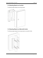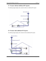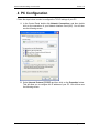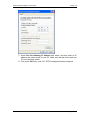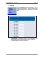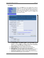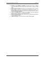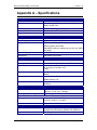
1
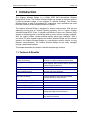
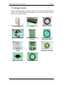
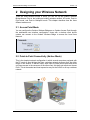
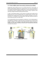
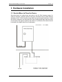
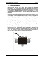
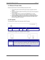
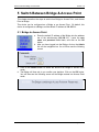
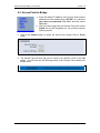
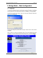
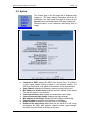
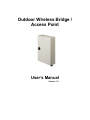
Outdoor Wireless Bridge /
Access Point
User’s Manual
Version: 1.0
Outdoor Wireless Bridge / Access Point
Version 1.0
Table of Contents
1
INTRODUCTION .................................................................................................................... 4
1.1
1.2
2
DESIGNING YOUR WIRELESS NETWORK......................................................................... 6
2.1
2.2
2.3
3
FEATURES & BENEFITS ..................................................................................................... 4
PACKAGE CONTENTS ........................................................................................................ 5
ACCESS POINT MODE ....................................................................................................... 6
POINT-TO-POINT CONNECTIVITY (AD-HOC MODE) .............................................................. 6
POINT-TO-MULTI POINT CONNECTIVITY (INFRASTRUCTURE MODE) ...................................... 7
HARDWARE INSTALLATION................................................................................................ 8
3.1
3.2
3.3
3.4
3.5
3.6
3.7
3.8
DECIDE WHERE TO PLACE THE BRIDGE ............................................................................. 8
LIGHTENING PROTECTION ................................................................................................. 9
ETHERNET & POWER CABLE ........................................................................................... 10
DC INJECTOR ................................................................................................................. 10
MOUNTING BRACKET ON THE WALL ..................................................................................11
MOUNTING BRACKET ON MAST WITH U-BOLTS...................................................................11
CONNECT WITHOUT ADDITIONAL DC INJECTOR ................................................................. 12
CONNECT WITH ADDITIONAL DC INJECTOR ....................................................................... 12
4
PC CONFIGURATION.......................................................................................................... 13
5
SWITCH BETWEEN BRIDGE & ACCESS POINT .............................................................. 15
5.1
5.2
6
BRIDGE MODE – WEB CONFIGURATION ........................................................................ 17
6.1
6.2
6.3
6.4
6.5
7
BRIDGE TO ACCESS POINT .............................................................................................. 15
ACCESS POINT TO BRIDGE .............................................................................................. 16
LOGGING IN .................................................................................................................... 17
SYSTEM ......................................................................................................................... 18
WIRELESS ...................................................................................................................... 19
STATION ......................................................................................................................... 20
ADMIN ............................................................................................................................ 21
ACCESS POINT – WEB CONFIGURATION ....................................................................... 23
7.1
7.2
7.3
7.4
7.5
LOGGING IN .................................................................................................................... 23
SYSTEM ......................................................................................................................... 24
WIRELESS ...................................................................................................................... 25
FILTERING ...................................................................................................................... 28
ADMIN ............................................................................................................................ 29
APPENDIX A – SPECIFICATIONS............................................................................................... 31
Page 2 of 31
Outdoor Wireless Bridge / Access Point
Version 1.0
Revision History
Version
Date
Notes
1.0
November 13, 2003
Initial Version
Page 3 of 31
Outdoor Wireless Bridge / Access Point
Version 1.0
1 Introduction
The Outdoor Wireless Bridge is a 2.4GHz IEEE 802.11b-compliant Wireless
Bridge/AP/AP Client. The Outdoor Wireless Bridge can operate as a point-to-point or
a point-to-multipoint bridge to link networks in different buildings. The Outdoor
Wireless Bridge is ideal for broadband ISP, enterprises, store merchants and small
business owners to create wireless backbone networks.
The Outdoor Wireless Bridge is designed for outdoor environments. With die-cast
watertight housing and an external lightning protector, this is a robust Outdoor
Wireless Bridge/AP/AP Client. It includes cost-effective Power-over- Ethernet (PoE)
adapter for supplying power to the Bridge when a power outlet is not easily available.
Also, the unique outdoor remote-mounted designs allow easy installation. With a
one-meter RF cable needed between the Outdoor Wireless Bridge and the external
antenna, the Outdoor Wireless Bridge is a cost-effective outdoor solution for long
distance communications. The Outdoor Wireless Bridge can be easily managed
through a web-based interface.
This chapter describes the features & benefits and package contents.
1.1 Features & Benefits
Features
Benefits
Point-to-Point/ Point-to-Multipoint
Wireless Connectivity
Lightning Protector (Surge Arrester)
Lets users transfer information between two
buildings or multiple buildings across the area
Includes 3 lightning protected factors located in
power amplifier, DC-Converter and DC-Injector and
a external lightning protector.
Avoid water invaded and weather corroded
Provides wireless link up to 25km(16miles) using
antennas and power amplifiers
Powerful data security
Watertight and Weatherproof
Excellent Range with Antenna and
Power Amplifier Options
64 /128-bit WEP Data Encryption
Hide SSID (AP Mode)
Avoids unallowable users sharing bandwidth,
increases efficiency of the network
DHCP Client/ Server
Simplifies network administration
MAC Address Filtering (AP Mode)
Ensures secure network connection
Power Amplifier Upgradeable
Flexibility and cost-effective
Power over Ethernet (PoE)
Easy installation and cost-effective
Web-based Configuration
Helps administrators to remotely configure or
manage the Bridge with web browser
Seamless Roaming
Allows users to travel between APs without losing
their network connection
Page 4 of 31
Outdoor Wireless Bridge / Access Point
Version 1.0
1.2 Package Contents
Open the package carefully, and make sure that none of the items listed below are
missing. Do not discard the packing materials, in case of return; the device must be
shipped in its original package.
Outdoor Wireless Bridge /
Access Point
Ethernet Inline Power
Injector
30 M Ethernet Cable
AC Power Adapter
Wall and Mast Mounting
Bracket
Reverse Polarity-N
Female RF Cable
U-Bolts
Screws
Installation CD-ROM
Lightning Arrestor
Grounding Wire
Page 5 of 31
Outdoor Wireless Bridge / Access Point
Version 1.0
2 Designing your Wireless Network
There are three different modes in which you can set up the Outdoor Wireless
Bridge/Access Point in the building-to-building wireless network: AP mode, Point to
Point mode, and Point to Multipoint mode. This chapter describes how the three
different modes work
2.1 Access Point Mode
You can configure the Outdoor Wireless Bridge as an Outdoor Access Point through
the web-based user Interface configuration. Users with a wireless client device
outside can connect to the Outdoor Wireless Bridge to access the Local Area
Network.
2.2 Point-to-Point Connectivity (Ad-hoc Mode)
This is the simplest network configuration in which several computers equipped with
the PC cards or client bridges that form a wireless network whenever they are within
range of one another. In ad-hoc mode, each client is linked peer-to-peer and would
only have access to the resources of the other client, this does not require an Access
Point. This is the easiest and least expensive way for the SOHO to set up a wireless
network.
Page 6 of 31
Outdoor Wireless Bridge / Access Point
Version 1.0
2.3 Point-to-Multi point Connectivity (Infrastructure Mode)
Infrastructure mode requires the use of an Access Point (AP). In this mode, all
wireless communication between two computers has to be via the AP whether the
AP is wired to an Ethernet network or stands alone. If used as a stand-alone, the AP
can extend the range of independent wireless LANs by acting a repeater, which
effectively doubles the distance between wireless stations.
If wired to an Ethernet network, the AP serves as a bridge and provides the link
between the server and the wireless clients. The wireless clients can move freely
throughout the coverage area of the AP while remaining connected to the server.
Since the AP is connected to the wired network, each client would have access to
server resources as well as to other clients.
In a very large facility such as an enterprise, a warehouse, or on a college campus, it
will probably be necessary to install more than one access point to cover an entire
building or campus. In this scenario, access points hand the client off from one to
another in a way that is invisible to the client, ensuring unbroken connectivity.
Wireless clients can roam seamlessly between different coverage areas and remain
connected to the network.
Page 7 of 31
Outdoor Wireless Bridge / Access Point
Version 1.0
3 Hardware Installation
3.1 Decide Where to Place the Device
Since this device is a radio device and works in the 2.4 GHz frequency range, for
optimum utilization, install this product away from microwave ovens or other devices
operating in the 2.4 GHz frequency range which can cause signal interference. Install
this device’s antenna in an area where the trees, buildings and large steel structures
do not obstruct the signal to and from the antenna. In conclusion, the antenna should
be located in the higher direct line-of-sight space.
Page 8 of 31
Outdoor Wireless Bridge / Access Point
Version 1.0
3.2 Lightening Protection
Radio transmitters, receivers, and RF cables require protection when attacked by
lightning strikes. The surge protectors contain fast response gas filled arrestors to
provide low let through voltage for fast rise time transients. This device is configured
to minimize circuit capacitance and the performance can be assured up to 2GHz.
Standard models provide protection for receivers and transmitters up to a 1KW
power level.
Installing this device outdoor may be subject to lightning strikes. To properly protect
your equipment, you should install the lightning arrestor to prevent an electrical surge
from traveling through the antenna cable and into the building. Lightning protection
for a building is more forgiving than protection of electrical devices. A building can
withstand up to 100,000 volts, but just a few volts may damage electrical equipment.
Direct earth grounding of the antenna and the Lightning Protector is necessary to
protect the installation from lightning and the build-up of static electricity. The ground
terminal is located on the lightning protector that attached with this unit. Connect one
end of the grounding cable to the Ground terminal and the other end to a good
ground connection. The package content contains a lightning arrestor, and should be
installed and grounded at the point where the cable enters the antenna.
The device connects to a Lightning Protector with a standard low-loss cable. The
Lightning Protector also connects to the outdoor antenna with a standard low-loss
cable. A longer cable can decrease the distance achievable between antennas. Use
an N-N Type (M) cable to connect this unit to the extra lightning protector and the
other N-N Type (M) cable to connect to the antenna as shown below.
Page 9 of 31
Outdoor Wireless Bridge / Access Point
Version 1.0
3.3 Ethernet & Power Cable
Follow the steps below to connect the Ethernet and power cable.
1. Connect the power cord to the DC-IN port on the rear panel of the DCInjector.
2. Connect an Ethernet cable to the RJ-45 port (To LAN) on the rear panel of
the DC-Injector.
3. Use the straight cable to connect to the HUB/SWITCH or use the
crossover cable to connect to the PC’s Network Interface Card (NIC).
4. Connect an Ethernet cable to the other RJ-45 port (To Bridge) on the rear
panel of the DC-Injector and connect the other end to the LAN1 (PoE)
port on the side of DC-Converter.
3.4 DC Injector
The following is an image of the front panel of the DC Injector.
LED
POWER
Function
Power indication
Color
Red
Status
ON
Description
Power is being supplied to this
device.
The following is an image of the rear panel of the DC Injector.
Port
To BRIDGE
To LAN
DC IN 48V
Description
Attaches to the power cord
Connects to an existing network. A straight Ethernet cable must be
used when connecting to a Swith/Hub, and a crossed Ethernet cable
must be used when connecting to a Network Interface Card (NIC) of a
PC.
Connects to the DC Converter’s LAN1 POE port.
Page 10 of 31
Outdoor Wireless Bridge / Access Point
Version 1.0
3.5 Mounting Bracket on the Wall
The following image displays the mounting bracket.
3.6 Mounting Bracket on Mast with U-bolts
The following image displays the mounting bracket on mast with U-bolts.
Page 11 of 31
Outdoor Wireless Bridge / Access Point
Version 1.0
3.7 Connect without additional DC Injector
The following image displays the connection without an additional DC injector.
3.8 Connect with additional DC Injector
The following image displays the connection with an additional DC injector.
Page 12 of 31
Outdoor Wireless Bridge / Access Point
Version 1.0
4 PC Configuration
Follow the steps below in order to configure the TCP/IP settings of your PC.
A. In the Control Panel double click Network Connections, and then double
click on the connection of your Network Interface Card (NIC). You will then
see the following screen.
B. Select Internet Protocol (TCP/IP) and then click on the Properties button.
This will allow you to configure the IP address of your PC. You will then see
the following screen.
Page 13 of 31
Outdoor Wireless Bridge / Access Point
Version 1.0
C. Select Use the following IP address radio button, and then enter an IP
address and subnet mask for your PC. Make sure that the device and your
PC is on the same subnet.
D. Click on the OK button, your PC’s TCP/IP settings have been configured.
Page 14 of 31
Outdoor Wireless Bridge / Access Point
Version 1.0
5 Switch Between Bridge & Access Point
This chapter describes the steps to switch from Bridge to Access Point, and Access
Point to Bridge.
This device can be configured as a Bridge or an Access Point. By default, this
device is configured as a Bridge, and the default IP address is 192.168.1.1.
5.1 Bridge to Access Point
a. Enter the default IP address of the Bridge into the address
bar of the web-browser (192.168.1.1). Leave the user
name and password fields blank, and click on the OK
button.
b. After you have logged into the Bridge, click on the Admin
link on the navigation bar. You will then see the following
screen.
c. Click on the Switch button to switch the device from Bridge to Access Point
mode.
d. The Bridge will then ask to you confirm your decision. Click on the OK button.
You will then see the following screen as the Bridge restarts into Access Point
mode.
Page 15 of 31
Outdoor Wireless Bridge / Access Point
Version 1.0
5.2 Access Point to Bridge
a. Enter the default IP address of the Access Point into the
address bar of the web-browser (192.168.1.1). Leave the
user name and password fields blank, and click on the
OK button.
b. After you have logged into the Access Point, click on the
Admin link on the navigation bar. You will then see the
following screen.
c. Click on the Switch button to switch the device from Access Point to Bridge
mode.
d. The Access Point will then ask you to confirm your decision. Click on the OK
button. You will then see the following screen as the Access Point restarts into
Bridge mode.
Page 16 of 31
Outdoor Wireless Bridge / Access Point
Version 1.0
6 Bridge Mode – Web Configuration
6.1 Logging In
To configure the Bridge through the web-browser, enter the IP address of the Bridge
into the address bar of the web-browser (default IP: 192.168.1.1), and press Enter.
You will then see the login window. Leave the User name Password fields blank,
then click on the OK button.
You may also change the password after you login. In order to do so, refer to section
6.4 Admin.
After you login, you will see the following screen. This screen displays the system
information. For more information about these settings refer to section 6.2 System.
Page 17 of 31
Outdoor Wireless Bridge / Access Point
Version 1.0
6.2 System
The System page is the first page that is displayed after
logging in. This page displays information about the AP
and Bridge. You may refresh this page by clicking on the
System link on the left-hand side of the page (image left).
Described below is the information listed along with an
image.
h
h
h
h
h
h
h
h
h
Connected to SSID: displays the SSID of the Access Point. The SSID is
a unique name shared among all points in your wireless network. The
SSID must be identical for all points in the network, and is case-sensitive.
Using Channel: displays the frequency channel currently being used.
MAC address of Access Point: displays the MAC address of the Access
Point that this device is connected to.
Current transmission rate: displays the transmission rate in Mbps.
Current Communication Quality: displays the signal strength.
MAC address of the Bridge: displays the MAC address of this Bridge.
Current IP address: displays the IP address of this Bridge.
Bridge firmware: displays the firmware version of this Bridge.
Results of the most recent scan: these are the results of a site survey
and displays the SSID, MAC address, channel number, signal strength,
and mode of Access Points of Stations in the area.
Page 18 of 31
Outdoor Wireless Bridge / Access Point
Version 1.0
6.3 Wireless
Click on the Wireless link on the navigation bar in order to
configure the wireless settings of this Bridge. The page
displays the current wireless settings and allows you to
make changes as you choose. Described below along with
an image are details on how to configure the wireless
settings of the Bridge.
h
h
h
Operating Mode: select a Point-to-Point or Point-to-Multi-point radio
button, depending on the type of network you would like to configure.
The SSID: displays the SSID of the Access Point. The SSID is a unique
name shared among all points in your wireless network. The SSID must be
identical for all points in the network, and is case-sensitive. Leaving this
field blank means using the SSID “any” and connecting to an Access Point
with the strongest available signal.
Channel: select a channel from the drop-down list, which is the shared
channel among all points in a point-to-point mode. The permissible
Page 19 of 31
Outdoor Wireless Bridge / Access Point
h
h
h
h
h
h
h
Version 1.0
channels depend on the regulatory domains.
Transmission Rate: select a supported transmission rate from the dropdown list, or select the default (automatic) to let the Bridge decide which
data rate to use.
Access Point Density: select from three densities (high, medium, low) to
scan the area for Access Points. This can be used in Point-to-Multi-point
mode only.
WEP enabled: place a check in this box if you would like to use WEP
encryption. WEP is an acronym for Wired Equivalent Privacy, a security
protocol for Wireless Local Area Networks (WLANs) defined in the 802.11
standard. WEP is designed to provide the same level of security as a wired
LAN.
WEP Key Length: select a WEP key length from the drop-down list.
Options available are 64-bit and 128-bit.
WEP Key 1~4: enter the WEP key. If you use WEP you must enter the
same key into the Access Points and Clients. For 64-bit keys you must
enter 10 hex digits. For 128-bit keys you must enter 26 hex digits. A hex
digit is defined as a number from 0 through 9 or letter from A through F.
Leaving this field blank indicates a key of all zeros.
WEP key to use: select a WEP key to use from the drop-down list.
Click on the Save button to confirm the changes.
6.4 Station
Click on the Station link on the navigation bar in order to
view a list of stations connected to this Bridge. The image
below depicts an example of a Bridge table.
Page 20 of 31
Outdoor Wireless Bridge / Access Point
Version 1.0
6.5 Admin
Click on the Admin link on the navigation bar in order to
configure the threshold values and login details. You may
also reboot this device and reset the setting back to the
factory defaults. Described below along with an image are
details on how to configure the administrative settings.
h
h
IP Address Mode: select Static or DHCP. If you select Static, you are
required to enter a default IP address, subnet mask, and gateway.
However, if you select DHCP the IP address, subnet mask, and gateway
will be assigned to this bridge via a DHCP server.
Default IP address: enter the IP address of this Bridge.
Page 21 of 31
Outdoor Wireless Bridge / Access Point
h
h
h
h
h
h
h
h
h
h
h
h
Version 1.0
Default subnet mask: enter the subnet mask for this Bridge.
Default Gateway: enter the IP address of the default gateway.
Device Name: enter a name for this Bridge. This field is optional.
Allow upgrade uploads: this Bridge can be upgraded via TFTP, therefore
place a check in this box if you would like to upgrade this device. It is
recommended that this box is unchecked during normal operation, when it
does not need to be upgraded.
Cloning bridge: place a check in this box to use MAC cloning. The Bridge
will set the wireless interface to use the MAC address of a device from the
wired side. Multiple devices can be connected but only the first device will
be cloned.
Fragmentation threshold: transmitted wireless packets larger than this
size will be fragmented to maintain performance in noisy wireless networks.
RTS threshold: transmitted wireless packets larger than this size will use
the RTS/CTS protocol to (a) maintain performance in noisy wireless
networks and (b) prevent hidden nodes from degrading performance.
User name: this user name is used in order to log into the Bridge. If you
would like to change the existing user name, enter it into this field.
Administrator password: type in the new password into this field, and reenter it for confirmation purposes in the field below.
Click on the Save button to confirm the changes. You must reboot the
Bridge in order for these new settings to take affect.
Reset to factory defaults: click on this button to reset the Bridge to its
factory default settings.
Switch to AP: click on this button to switch to Access Point mode.
Page 22 of 31
Outdoor Wireless Bridge / Access Point
Version 1.0
7 Access Point – Web Configuration
7.1 Logging In
To configure the Access Point through the web-browser, enter the IP address of the
Access Point into the address bar of the web-browser (default IP: 192.168.1.1), and
press Enter.
You will then see the login window. Leave the User name and the Password field
blank, and then click on the OK button.
You may change the user name and password after you login. In order to do so,
refer to section 7.5 Admin.
After you login, you will see the following screen. This screen displays the system
information. For more information about these settings refer to section 7.2 System.
Page 23 of 31
Outdoor Wireless Bridge / Access Point
Version 1.0
7.2 System
The System page is the first page that is displayed after
logging in. This page displays information about the
Access Point. You may refresh this page by clicking on the
System link on the left-hand side of the page (image left).
Described below is the information listed along with an
image.
h
h
h
h
h
h
AP firmware: displays the version of the firmware installed on the Access
Point.
WLAN Primary firmware: displays the primary firmware of the wireless
LAN card inside the Access Point.
WLAN Secondary firmware: displays the secondary firmware of the
wireless LAN card of the Access Point.
MAC address of AP: displays the MAC address of the Access Point.
Current IP address: displays the IP address of the Access Point.
Associations: lists all the stations that are associated with the Access
Point, along with the amount of time since packets were transferred to and
from each station. If a station is idle for too long, it is removed from this list.
You may have to reload this page to view the current settings.
Page 24 of 31
Outdoor Wireless Bridge / Access Point
Version 1.0
7.3 Wireless
Click on the Wireless link on the navigation bar in order to
configure the wireless settings of Access Point. The page
displays the current wireless settings and allows you to
make changes as you choose. Described below along with
an image are details on how to configure the wireless
settings of the Access Point.
Page 25 of 31
Outdoor Wireless Bridge / Access Point
h
h
h
h
h
h
h
h
Version 1.0
Access Point name: enter a name for the Access Point.
The SSID: displays the SSID of the Access Point. The SSID is a unique
name shared among all points in your wireless network. The SSID must be
identical for all points in the network, and is case-sensitive. Leaving this
field blank means using the SSID “any” and connecting to an Access Point
with the strongest available signal.
Channel: select a channel from the drop-down list, which is the shared
channel among all points in a point-to-point mode. The permissible
channels depend on the regulatory domains.
Basic Rates: select the basic rates by placing a check in required boxes.
The basic rates should be set based on the speed of the wireless network.
You must select 1 –2 Mbps if older 802.11 compliant equipment resides on
your network, such as wireless adapters that support only 1 or 2 Mbps.
However, selecting 1 –2 Mbps does not limit the basic transfer rate of
faster adapters.
Supported Rates: select all the supported rates at which the client with
communicate with the Access Point by placing a check in the required box.
Transmission Rate: select a supported transmission rate from the dropdown list, or select the default (automatic) to let the Bridge decide which
data rate to use.
Preamble Type: select a preamble type from the drop-down list, options
available are: long, short, or both.
Visibility Status: select Visible or Invisible. If Invisible is selected, the
Page 26 of 31
Outdoor Wireless Bridge / Access Point
h
h
h
h
h
h
h
h
h
h
h
Version 1.0
Access Point is protected from a discovery or site survey, and all wireless
clients must specify the SSID to associate with the Access Point. If Visible
is selected, the SSID of the Access Point is broadcasted over the wireless
network.
WEP enabled: place a check in this box if you would like to use WEP
encryption. WEP is an acronym for Wired Equivalent Privacy, a security
protocol for Wireless Local Area Networks (WLANs) defined in the 802.11
standard. WEP is designed to provide the same level of security as a wired
LAN.
WEP Key Length: select a WEP key length from the drop-down list.
Options available are 64-bit and 128-bit.
WEP Key 1~4: enter the WEP key. If you use WEP you must enter the
same key into the Access Points and Clients. For 64-bit keys you must
enter 10 hex digits. For 128-bit keys you must enter 26 hex digits. A hex
digit is defined as a number from 0 through 9 or letter from A through F.
Leaving this field blank indicates a key of all zeros.
WEP key to use: select a WEP key to use from the drop-down list.
Maximum associated stations: this limits the number of stations that can
associate with the Access Point.
Fragmentation threshold: this value indicates how much of the Access
Point’s resources are devoted to recovering packet errors. The value
should remain at its default setting. If you decrease this value too much
you may encounter high packet error rates, however if you increase it too
much it will affect overall performance. Therefore, it is recommended to
leave this value at its default of 2346.
RTS threshold: transmitted wireless packets larger than this size will use
the RTS/CTS protocol to (a) maintain performance in noisy wireless
networks and (b) prevent hidden nodes from degrading performance.
Beacon period: this value indicates the frequency interval of the beacon.
The beacon is a packet broadcasted by the Access Point to keep the
network synchronized. A beacon consists of the wireless LAN service area,
IP address, broadcast destination address, time stamp, Delivery Traffic
Indication Map (DTIM) and Traffic Indicator Message (TIM).
DTIM Interval: this value indicates the interval of the Deliver Traffic
Indicator Map (DTIM). The DTIM field is a countdown field informing
clients of the next window for listening to broadcast and multicast
messages. When the Access Point has buffered broadcast of multicast
messages for associated clients, it sends the next DTIM with a DTIM
interval value. Clients hear the beacons and then awaken to receive the
broadcast or multicast messages.
Multicast PM buffering: enabling this function can avoid network
congestion when there are too many clients to transmit data
simultaneously.
Click on the Save button to confirm the changes.
Page 27 of 31
Outdoor Wireless Bridge / Access Point
Version 1.0
7.4 Filtering
Click on the Filtering link on the navigation bar in order to
configure MAC address filters. Described below along with
an image are details on how to configure the MAC address
filters
h
h
Enable filtering: by enabling this function, only the clients whose MAC
addresses are listed in the fields can associate with the Access Point.
Click on the Save button to confirm the changes.
Page 28 of 31
Outdoor Wireless Bridge / Access Point
Version 1.0
7.5 Admin
Click on the Admin link on the navigation bar in order to
configure the user name and password to log into the
device. You may also reboot this device and reset the
setting back to the factory defaults. Described below along
with an image are details on how to configure the
administrative settings.
h
h
h
h
h
h
IP Address Mode: select Static or DHCP. If you select Static, you are
required to enter a default IP address, subnet mask, and gateway.
However, if you select DHCP the IP address, subnet mask, and gateway
will be assigned to this Access Point via a DHCP server.
Default IP address: enter the IP address of this Access Point.
Default subnet mask: enter the subnet mask for this Access Point.
Default Gateway: enter the IP address of the default gateway.
User name: this user name is used in order to log into the Access Point. If
you would like to change the existing user name, enter it into this field.
Administrator password: type in the new password into this field, and reenter it for confirmation purposes in the field below.
Page 29 of 31
Outdoor Wireless Bridge / Access Point
h
h
h
h
h
Version 1.0
Isolation: select Enable or Disable. By enabling this feature, wireless
clients associated with the Access Point will be able to connect to each
other.
Allow upgrade uploads: this Bridge can be upgraded via TFTP, therefore
place a check in this box if you would like to upgrade this device. It is
recommended that this box is unchecked during normal operation, when it
does not need to be upgraded.
Click on the Save button to confirm the changes. You must reboot the
Bridge in order for these new settings to take affect.
Reset to factory defaults: click on this button to reset the Access Point to
its factory default settings.
Switch to Bridge: click on this button to switch to Bridge mode.
Page 30 of 31
Outdoor Wireless Bridge / Access Point
Version 1.0
Appendix A – Specifications
General
Data Transfer Rate
11, 5.5, 2 and 1 Mbps, Auto Fall-Back
LED Indicator
Power: Bridge, DC Converter, Power Amplifier
Others: WLAN, LAN
Compatibility
IEEE 802.11b compliant
Regulation Certifications
FCC Part 15/UL, ETSI 300/328/CE
Power Supply
12V DC/ 1A
Network
Topology
Point-to-Point/ Point-to-Multipoint/ Infrastructure
Firmware Upgrade
Upgrade firmware via Web
Security
MAC address filtering (AP Mode)
WEP encryption (64/128-bit)
Hide SSID in beacons, stations can not use “any” SSID
(AP Mode)
IP Auto-configuration
DHCP Client/ Server
Management
Web-based configuration
Radio
Frequency Band
2.400〜2.484 GHz
Radio Type
Direct Sequence Spread Spectrum (DSSS)
Operation Channels
11 for North America, 14 for Japan,
13 for Europe, 2 for Spain, 4 for
France
Modulation
11 Mbps / 5.5 Mbps CCK;2 Mbps: DQPSK;1 Mbps:
RF Output Power
23dBm(200mW)--FCC
20dBm(100mW)--CE
RF Connector
N-Type connector (N-Female Reverse—FCC
Standard)
DBPSK
Environment
Temperature Range
Humidity (non-condensing)
Physical Specifications
-10 to 55° C (32 to 131 °F) -operating
-20 to 80 ° C(-4 to 176 °F) -storage
5%〜95% typical
Dimensions
354(L)mm * 249(W)mm * 89(H)mm
13.9(L)in. * 9.8(L) in. * 3.5(H) in.
Weight
2.1Kg
Electrical
Power Supply
Surge Arrester
Active Ethernet (power over Ethernet) –48 VDC/0.7A
External Unit: Auto sensing 100/240 VAC; 50/60 Hz
20KA Surge Current
Page 31 of 31