1
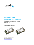
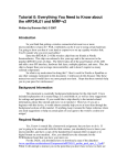
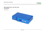
E2L Limited
User Manual
™
LANDMARKA
A manual for users of the Landmarka™
low power radio telemetry system.
Operation, deployment and
maintenance.
Revision 1.02 © E2L Holdings 2009
Contents
LANDMARKA Low Power Radio Telemetry
About this manual
Landmarka
Important Installation Warning
1.0 System function
1.1 System capacity
1.1.0 Basic system
Contact inputs
Pulse inputs
Analogue inputs
1.1.1 Extended system
2.0 Operating instructions
2.1 Transmitter
2.1.1 General Layout
2.1.2 Configuration
2.1.2.1 Address setting
2.1.2.2 Reporting rate
2.1.2.3 Interface Options
Digital input bias
Instrument Power
Analogue inputs
2.1.3 Connecting instruments
2.1.3.0 Digital or switch inputs
2.1.3.1 Pulse inputs
2.1.3.2 Analogue inputs
2.1.2.3 Analogue instrument wiring
2.1.4 Calibration
J373.Landmarka/UserManual.1.02.doc
2.2 Receiver
2.2.1 Menu System
2.2.1.1 DISPLAY menu
2.2.1.2 USER VARIABLES menu
2.2.1.3 CALIBRATE menu
2.2.1.4 CONTRAST menu
2.2.1.5 PROTOCOL menu
2.2.1.6 ABOUT menu
2.2.2 Configuration
2.2.3 Connecting to external devices
2.2.3.0 Digital or switch outputs
2.2.3.1 Pulse outputs
2.2.3.2 Analogue outputs
2.2.3.3 Analogue instrument wiring
2.2.3.4 Alarm outputs
2.2.3.5 Power outputs
2.2.3.6 Power Inputs
2.2.3.7 Serial Outputs
2.2.3.8 Antenna connection
2.2.3.9 Bus extension (system builders)
2.2.5 Interfacing to a serial device (for advanced users)
2.2.5.0 LANDMARKA protocol
2.2.5.1 MODBUS protocol
3.0 Rapid Setup Guide
J373.Landmarka/UserManual.1.02.doc
About this manual
Landmarka
We have endeavoured to make the Landmarka simple to use but please read
this manual to familiarise yourself with all of the operations, and especially the
safety instructions. Whilst this manual is lengthy this is mostly due to the amount
of pictures and diagrams – Landmarka’s strength is that it is extremely simple to
use.
FOR A RAPID SET-UP GUIDE GO DIRECTLY TO SECTION 3.0.
As with any machine the care that you give it will reflect on its operational life and
reliability. Please read this manual and take note of the safety and care
instructions.
Because of the sophisticated design of Landmarka none of the internal parts are
user serviceable. Only have your instrument serviced or repaired by an approved
E2L agent who has access to the correct equipment and spares.
This machine comes with a one-year warranty, if you have any problems or
questions please contact your agent.
In each section we guide you through the investigation process, with examples,
plus other information that may help.
Diagrams have been used as much as possible but you should note that these
may not always exactly match the machine itself due to the continual policy of
product improvement.
If you have any questions or any advice on improving both Landmarka and this
manual please contact your agent.
An organisation should appoint an Instrument Administrator responsible for
setting the parameters of the instrument. They will need to define the
configuration which best suits their monitoring tasks and maintain any record
keeping.
IMPORTANT INSTALLATION WARNING
Power must NOT be applied UNTIL the antennae have been fully installed.
Failure to comply with this instruction may result in permanent damage which is
outside the terms of our warranty.
Antennae, their feeder cables and connectors are crucial components for
optimum performance of radio systems. At no time should the inside of cables or
connectors get wet and good working practice should be applied throughout
installation.
J373.Landmarka/UserManual.1.02.doc
Landmarka™ Signal Cable
Elimination
This manual provides necessary instructions for
successfully installing and operating the Landmarka™
low power radio telemetry system.
1.0 System function
The purpose of the system is to eliminate the need for cables between
monitoring instruments and junction boxes or control rooms. It is effective over
ranges up to about 10km. The system can also be used as an alternative to
signal cable in awkward applications such as rotating machinery or difficult
situations such as crossing roads or railways
The best way to visualise the system is to think of it as a piece of cable; the
signal that goes in one end comes out of the other.
Signal in
Signal out
Signal out
Signal in
Transmitter
Receiver
There is no need to become involved with any higher level equipment such as
computers or hand-held terminals. Calibration of analogue signals can be simply
achieved in the field using a screwdriver and current or voltage sources.
It is easily understood, easily installed, licence free, and cost effective compared
to other means of data transmission.
Landmarka is designed for low bandwidth signals found in monitoring
applications typical of the water and electricity utilities. It has a secure
communication method proven in service over the last 20 years so the signal’s
integrity is highly reliable.
Landmarka also has additional system health features such as remote power
loss detection, communication quality indicators, making it superior to cable in
many situations.
J373.Landmarka/UserManual.1.02.doc
1.1 System capacity
1.1.0 Basic system
The basic Landmarka system consists of a transmitter and a receiver. It is a one
way system and securely transports signals from the transmitter to the receiver.
The transmitter has a capacity for 8 contact inputs, 2 pulse inputs and 2
analogue signals.
The receiver has exactly the same outputs as the transmitter inputs and so the
system can be seen as a multi-core cable:
8 contacts
2 pulses
2 analogues
8 contacts
2 pulses
2 analogues
Receiver
Transmitter
Contact inputs
These are ‘volt-free’ or ‘switch’ inputs. A change in one of these inputs causes
the corresponding output to change. The outputs are also simple isolated switch
outputs.
Typical devices with such signals are float switches, position switches, intruder
alarms, pump on/off status, power fail, threshold indicators, wind vanes and
similar two-state or ON/OFF devices.
Pulse inputs
These are also ‘volt-free’ or ‘switch’ inputs. However the transmitter counts the
pulses and sends them to the receiver which outputs the same number of
pulses. These pulse counters are often referred to as totaliser inputs.
Typical instruments are flow gauges, anemometers, electricity meters,
tachometers, tipping bucket rain gauges, etc.
Analogue inputs
These are voltage or current inputs. The signals can range from 0-20mA, 0-1V,
0-10V. At the transmitter they are referenced to supply ground. At the receiver
they are both referenced to supply ground, and, for the 4-20mA signal, isolated
suitable for external loop power.
1.1.1 Extended system
The basic Landmarka receiver comes with the capacity to receive another
transmitter. This means that to expand the system only one more transmitter
needs to be added:
8 contacts
2 pulses
2 analogues
Transmitter 1
16 contacts
4 pulses
4 analogues
8 contacts
2 pulses
2 analogues
Transmitter 2
Receiver
J373.Landmarka/UserManual.1.02.doc
2.0 Operating instructions
Landmarka is essentially a ‘fit and forget’ device; once the unit has been
installed, configured and calibrated it is unlikely that anything will be changed.
Refer to our installation guides that cover antenna mounting and tips on getting
the best over long range systems. This manual covers the configuration and
calibration of the system.
2.1 Transmitter
The Landmarka transmitter is a low powered 12V system. Its power can be
derived from local mains supply, batteries or 12V solar or wind supply.
For legal reasons the transmitter cannot emit more than 500mW of RF power.
The standard transmitter uses a 10mW radio so directional antenna can be used
with great effect. Please discuss your antenna choice with your agent.
If you are using the 500mW radio option then the antenna must have a gain of
0dB or less.
2.1.1 General Layout
Transmitter Module
Power
Supply
Battery
Backup
A backup battery can provide continued operation during a temporary power
failure and is trickle charged via the transmitter’s circuitry. If a solar or wind
generator is used then a separate battery is required.
2.1.2 Configuration
All configuration is simply achieved by setting switches on the controller. There
are essentially three steps to configuring the transmitter:
1) Address setting
2) Reporting rate
3) Interface options
J373.Landmarka/UserManual.1.02.doc
2.1.2.1 Address setting
Address setting defines both where the data is coming from, and where the data
is going to. On a site using several Landmarka systems then having different
addresses allows data to be directed from specific transmitters to specific
receivers.
Receiver address
This is where the data from this
transmitter will go.
Values can be
0,1,2,3,4,5,6,7,8,9,A,B,C,D,E or F
Transmitter address
This defines which transmitter this unit
is, so that the receiver can detect which
output channel to use.
Typically this will be 0 or 1
For a single transmitter system always set the transmitter address to ‘0’.
2.1.2.2 Reporting rate
The reporting rate is the frequency that the transmitter wakes up and sends a
message. When data is sent the ‘ACTIVE’ LED flashes 5 times. The LED also
flashes once every 15s to show that the transmitter is running.
Setting the report rate switch determines
the wake-up period according to the following table:
0
1
2
3
4
5
6
7
8
9
A
B
C
D
E
F
15 s
30 s
1m
2m
3m
4m
5m
6m
7m
8m
9m
10 m
15 m
20 m
25 m
30 m
Active LED
Report Rate Switch
J373.Landmarka/UserManual.1.02.doc
2.1.2.3 Interface Options
There are several switches that accommodate various instrument specifications.
In particular digital inputs can be pulled up or down, instrument power can be
switched on prior to reading (to save power), and the period of power up can be
changed. Analogue inputs can be defined as current or voltage.
Digital input bias
In most cases the digital input device will
be a volt-free contact or switch. In that
case the digital inputs require a lowpower pull-up so the ‘DIGITAL PULLUP’
switch should be in the 5V position.
However some instruments are active
high and in that case the switch should
be moved to the 0V position.
Digital input pullup switch
In the picture the switch is in its normal
position for volt-free or switch inputs.
Instrument Power
If the instrument requires power then
this can be supplied from the controller.
The supply can be permanently on or,
for low power consumption, the supply
can be switched on just before the
instrument is read.
If the switched power mode is being
used then the settling time before
reading the instrument can be selected
as either 0.1s or 1s.
In the picture switched power with 1s
settling time is selected.
1s or 0.1s settling time
selection switch
Permanent or switched
instrument supply switch
Analogue inputs
There are two analogue inputs and each
one can be selected as current or
voltage inputs.
Moving the analogue mode switch
upwards selects Current (I); downwards
selects voltage (V).
Switch 1 corresponds to analogue input
1; switch 2 corresponds to analogue
input 2.
In the picture both analogue inputs are
set for current.
Current or Voltage switch
analogue channel 2
Current or Voltage switch
analogue channel 1
J373.Landmarka/UserManual.1.02.doc
2.1.3 Connecting instruments
All connections are clearly marked and conform to standard industry practice.
2.1.3.0 Digital or switch inputs
There are 8 inputs available for
digital signals which are divided into
two groups of four.
The lower four (1-4) are defined as
‘alarm’ inputs. Any change on these
inputs will cause the transmitter to
immediately wake-up and transmit.
The upper four (5-8) are defined as
‘digital’ inputs and the status of these
inputs is transmitted at the predefined report rate (see 2.1.2.2).
Every input has a common pin
adjacent to it for easy connection.
In the picture there are 3 alarm
inputs on 1, 2 & 3, and 3 digital
inputs on 6, 7 & 8.
2.1.3.1 Pulse inputs
There are 2 inputs available for pulse
signals from instruments with switch
or volt-free contact outputs.
Every input has a common pin
adjacent to it for easy connection.
The maximum input frequency is
36Hz.
2.1.3.2 Analogue inputs
There are 2 analogue channels
available, each with 3 terminal
connections depending on both the
range and mode of the input.
Connection diagrams are given on
the next section.
In the picture Analogue channel 1 is
either a 0-20mA or a 0-1V instrument
(depending on the switch positions in
section 2.1.2.3)
Similarly Analogue channel 2 is a 010V instrument.
J373.Landmarka/UserManual.1.02.doc
2.1.3.3 Analogue instrument wiring
0 – 10V Instrument
Analogue
instrument
0-10V output
12V
POWER O/P
10V
I/1V
ANALOGUE1
0V
ANALOGUE
I
V
1 2
Analogue mode = voltage
0 – 1V Instrument
Analogue
instrument
0-1V output
12V
POWER O/P
10V
I/1V
ANALOGUE1
0V
ANALOGUE
I
V
1 2
Analogue mode = voltage
4 – 20mA or 0 – 20mA Instrument
12V
Analogue
instrument
POWER O/P
10V
4-20mA/0-20mA output
I/1V
ANALOGUE1
0V
ANALOGUE
I
V
1 2
Analogue mode = current
2.1.3.4 Power Inputs
BATT 14.5V
0V
+12V
Battery
0V
+12V
PSU
D.C.<16V
The LANDMARKA transmitter is 12VDC powered and can be configured for
battery backup. It requires a DC input and this provides a trickle charge for the
batteries. Connection is via the large four way terminal plug.
Fuse should be 2A slow-blow.
J373.Landmarka/UserManual.1.02.doc
2.1.4 Calibration
Calibration in the field is extremely simple and can be achieved using a small
screwdriver and a current or voltage source.
The method is:
1) Configure the correct analogue channel to be current or voltage using the
configuration switches.
2) Connect a current or voltage source to the analogue input terminals
3) Adjust the current or voltage source to be full scale. For voltage this will be
10.0V or 1.0V; for current it will be 20.0mA.
4) Press the ‘CALIBRATE’ button.
The ‘AN1’ LED will
illuminate indicating
that you are
calibrating analogue
channel 1.
Calibrate button
5) Using a small screwdriver adjust the SPAN and look at the
green ‘ACTIVE’ LED. If the LED is off then turn the screwdriver
clockwise, if it is on turn it anticlockwise.
When the LED flashes then the unit is calibrated.
6) Press the ‘CALIBRATE’ button again. The ‘AN2’ LED will illuminate indicating
that you are calibrating analogue channel 2.
7) Repeat step ‘5’ above.
8) Finally press the ‘CALIBRATE’ button again and both AN1 & AN2 lights will be
off; the ACTIVE LED will then flash 5 times indicating normal operation.
J373.Landmarka/UserManual.1.02.doc
2.2 Receiver
The Landmarka receiver is powered from 24V. Its power should be derived from
local mains supply via a Landmarka mains power module. Receivers can have
antennae with a gain greater than 0dB. However, in most cases a simple 0dB
gain antenna will suffice.
As mentioned in section 1.1 the standard Landmarka receiver can service two
transmitters. (In expanded systems it can provided the outputs for up to 16
transmitters). In the receiver description below we shall assume a single
transmitter system with transmitter address ‘0’. All the descriptions for transmitter
address ‘0’ apply equally to transmitter address ‘1’ – it is merely the next physical
set of output terminals.
Power Supply
Receiver Communications
Module
Backup batteries
Receiver Output Module
Antenna Connection
The Landmarka Receiver differs from the Transmitter in that it has an LCD
display and a simple keyboard which enables easy configuration and calibration
of the channels. It also provides diagnostics for factory and site testing.
The display also reports received signal strength which is extremely useful when
positioning directional antennae. The keyboard consists of 5 buttons which allow
for:
1) UP and DOWN scrolling of menu options
2) + and – changes variable values
3) ENTER to select options, or to exit menus
J373.Landmarka/UserManual.1.02.doc
All menus work in the same way and are very intuitive.
2.2.1 Menu System
The full menuing system is below. However, once the system is installed and
calibrated only a few of the screens are generally unused. The DISPLAY menus
provide access to numerical information if required.
Configuration is handled by the USER VARIABLES menu, and calibration by the
CALIBRATE menu.
DISPLAY
o Signal Strength
o Channel Data
o Monitor
o Return
Landmarka
o Display
o User
variables
o Calibration
o Contrast
o Protocol
ABOUT
Supplier
Phone number
Revision
PROTOCOL
Interface
Slave Address
Serial Mode
Return
SERIAL MODE
RS485
RS232
USER VARIABLES
o Addressing
o Timeout
o Digital
o Return
SIGNAL STRENGTH
Bargraph of RSSI
Channels
Channel number
Analogue1
Analogue2
Digitals
Pulse Counter 1
Pulse Counter2
Status
MONITOR
Raw received data
ADDRESSING
System address
TIMEOUT
Global timeout (mins)
DIGITAL
Normally open/closed
Retain/Fail Safe
CONTRAST
+/- to change
INTERFACE
MODBUS
LANDMARKA
CALIBRATE
Exercise digital outputs
Exercise pulse outputs
Calibrate analogue
outputs
J373.Landmarka/UserManual.1.02.doc
2.2.1.1 DISPLAY menu
The display menu allows the user to
view the latest data to be received
on a channel specific basis. It also
provides a bargraph display for radio
signal strength and a data monitor
which indicates all received data in its raw form. Pressing the ENTER key will
always exit from the sub-menu. The main features of these menus are detailed
below:
SIGNAL STRENGTH
The received signal strength is a
very useful utility to see if there is a
good radio signal present. The scale
indicates 0 to 100%.
This screen is also invaluable when
using a directional antenna in order
to determine the optimal position for
good reception.
CHANNEL DATA
Channel data allows the user to see
the last received data for a specific
channel.
The channel can be selected by
pressing + or – keys. In the example
the receiver address (R) is set to ‘F’,
and the transmitter address (T) is
set to ‘1’. These correspond exactly
to the switch positions in the
transmitter controller.
The UP/DOWN keys scroll through
the various types of data; namely
Digital inputs, Analogue 1 &
Analogue 2, Pulse 1 and Pulse 2, as
well as transmitter health such as
battery and PSU condition and the
rate switch position in the
transmitter.
MONITOR
The data monitor supplies the raw data as it is received in real time. This is
provided for advanced and factory use.
RETURN
This returns to the main Landmarka menu.
J373.Landmarka/UserManual.1.02.doc
2.2.1.2 USER VARIABLES menu
As with the transmitter the main
configuration tasks are:
1) Address setting
2) Setting report rate timeout
3) Interface options
These variables are set using the USER VARIABLES menu.
ADDRESSING
The receiver has an address
identified by the numbers 0 to 9, or
a letter A, B, C, D, E or F. This
corresponds to the switch position in
the transmitters for the receive (or
system) address.
Pressing + or – changes the receiver or system address; ENTER saves the
address. Only data received which matches this address will then be output.
TIMEOUT
Landmarka tracks the condition of its
communication channel. If a
message is not received within a
specific time then a communication
alarm can be raised.
The length of timeout can be chosen by pressing the + or – keys. The choice of
timeout should be adjusted to the sensitivity of the application. Typically a timeout
just over twice the transmitter rate switch is a good working rule. So for a
transmitter with a RATE switch set at position ‘4’ (= 3 minutes) then a timeout of 7
minutes would be sensible.
DIGITAL
Many systems require variations on
their digital input status. For
instance, normally closed or
normally open contacts.
This feature is included in
Landmarka and adds a facility that
normal direct cabling cannot do.
Also should there be a
communication failure the choice to
retain the last received reading or
revert to a fail safe condition is also
provided.
+ or – changes the options; UP or
DOWN scrolls the options; ENTER
saves the choices and returns from
this sub-menu.
J373.Landmarka/UserManual.1.02.doc
2.2.1.3 CALIBRATE menu
The calibrate menu allows the user to both calibrate the analogue channels and
to check the pulse and digital output functions. Pressing UP or DOWN scrolls
through these options.
DIGITAL OUTPUTS
Pressing + or – will cycle the digital
outputs through the screens
providing four variations of output
condition.
Each digital output has a
corresponding LED which indicates
its output status.
This facility is also useful for
providing predefined inputs into
monitoring equipment or telemetry
outstations.
This method also exercises the
alarm outputs.
PULSE OUTPUTS
In the same manner the pulse
outputs can be exercised.Pressing
+ or – will provide a pulse at the
output.
ANALOGUE OUTPUTS
Pressing the + or – keys in this
menu causes a current and voltage
to be output on all the analogue
outputs.
The calibration process for
adjusting offsets and span per
analogue output is explained in
section 2.2.4.
J373.Landmarka/UserManual.1.02.doc
2.2.1.4 CONTRAST menu
This menu adjusts the contrast of the display. + or – adjusts and ENTER exits to
the main menu.
2.2.1.5 PROTOCOL menu
(This section is only relevant if you are interfacing to a serial device)
If the LANDMARKA is to interface
directly to a serial device such as a
datalogger or computer, the protocol
menu allows the user to choose
which protocol to use, and what
physical interface.
Pressing UP or DOWN scrolls through the options. ENTER selects a sub-menu.
INTERFACE
Pressing + or – will cycle the choices
of interface type.
The two choices are the industry
standard MODBUS database
protocol, or a simpler ASCII serial
event driven protocol proprietary to
the LANDMARKA product.
SLAVE ADDRESS
Slave address selection is only
relevant if MODBUS protocol has
been selected.
Pressing + or – will change the MODBUS slave address. ENTER will save and
exit to the Protocol sub-menu.
SERIAL MODE
Pressing + or – will cycle the choice
between RS485 or RS232 serial
interfaces.
2.2.1.6 ABOUT menu
This menu supplies information about local supplier contact and revision number.
UP or DOWN scrolls through the information; ENTER exits to the main menu.
J373.Landmarka/UserManual.1.02.doc
2.2.2 Configuration
The configuration required at the receiver is merely matching up the addressing
choices of the transmitter.
Section 2.1.2.1 describes setting the receiver address as ‘where the data is being
sent to’. This address can also be seen as a ‘system address’ which means that
all the devices in a particular system share this same address.
In the example below all the transmitters with the RX address switch set to ‘7’
communicate with receiver number ‘7’. Any devices on another RX address do
not communicate even if they are on the same radio frequency.
Transmitter
TX addr = 0
RX addr = 3
Transmitter
TX addr = 0
RX addr = 7
Receiver
RX addr = 3
System ‘7’
System ‘3’
Transmitter
TX addr = 1
RX addr = 7
Receiver
RX addr = 7
Setting the receiver address is achieved by means of the menu system described
in section 2.2.1.2.
The remaining task is to ensure that the transmitters are assigned to the correct
outputs on the receiver. This is calculated by adding the value of the receiver’s
‘TX Address’ switch to the channel number (0 or 1) which should equal the
Transmitter’s TX address switch. This is simpler by example:
TRANSMITTER
RECEIVER
TX Address
TX Address
TX+Channel
OUTPUT appears on
0
0
0 or 1
Channel0
0
1
1 or 2
no output
1
0
0 or 1
Channel1
4
4
4 or 5
Channel0
5
4
4 or 5
Channel1
For most single transmitter point to point systems TX address should be set to 0
and the outputs will appear on Channel 0.
J373.Landmarka/UserManual.1.02.doc
2.2.3 Connecting to external devices
LANDMARKA outputs hardwired signals as a direct mimic to transmitter inputs.
This means that for any set of transmitter inputs, exactly the same signals are
output at the receiver end. Certain system health signals are also provided as
hardwired connections.
In addition provision has been made (but is not a requirement) to interface via a
serial port to outstations, computers, PLCs or dataloggers.
Finally the link may be used as an analogue signal converter changing current to
voltage and vice versa, as well as modifying ranges.
2.2.3.0 Digital or switch outputs
There are 8 outputs available each of which is opto-isolated and volt-free.
Each output is capable of switching 60VAC (peak) at 400mA.
Each switch output has an LED indicator and is connected via a corresponding
two terminal screw contact. In the picture digital outputs 3 and 5 are in use.
DIGITAL
PLC,
Datalogger,
Alarm panel,
etc.
1
2
3
4
5
6
7
8
2.2.3.1 Pulse outputs
There are 2 outputs available each of which is opto-isolated and volt-free.
They have the same specification as the digital outputs
Each pulse output has an LED indicator and is connected via a corresponding
two terminal screw contact. In the picture pulse output 2 is being used.
PLC,
Datalogger,
Alarm panel,
etc.
PULSE
1
2
2.2.3.2 Analogue outputs
There are 2 analogue channels available per TX channel. They can be output as
0-1V, 0-10V, 0-20mA or as an isolated 4-20mA.
Connection diagrams are given below.
J373.Landmarka/UserManual.1.02.doc
2.2.3.3 Analogue instrument wiring
0 – 10V Output
+12V
0V
-12V
0-1V
0-10V
0-10V output
PLC,
Datalogger,
Alarm panel,
etc.
0V
POWER OUTPUT
ANALOGUE 1
0-20mA
4-20mA
0 – 1V Output
PLC,
Datalogger,
Alarm panel,
etc.
+12V
0V
-12V
0-1V
0-10V
0-1V output
0V
POWER OUTPUT
ANALOGUE 1
0-20mA
4-20mA
0 – 20mA Non-isolated Output
This is the non-isolated output so the bottom of the loop must be referenced to
0V. The loop power can be derived from an external supply or the LANDMARKA
power output. An example of each is given:
LANDMARKA loop power supply
Loop
powered
device. e.g.
meter,
annunciator,
etc.
+
1283
12V
-
+12V
0V
-12V
0-1V
0-10V
POWER OUTPUT
ANALOGUE 1
0-20mA
4-20mA
0-20mA sink
External loop power supply
Loop
powered
device. e.g.
meter,
annunciator,
etc.
+
+
LOOP
PSU
1283
0-20mA sink
0V
+12V
0V
-12V
0-1V
0-10V
0-20mA
4-20mA
POWER OUTPUT
ANALOGUE 1
J373.Landmarka/UserManual.1.02.doc
4 – 20mA Isolated Output
This is the isolated output so the connection can be made anywhere in the loop.
Normally the loop power is derived from an isolated external supply (these can be
individual LANDMARKA PSU modules) or a non-isolated supply can be sourced
from the LANDMARKA power output. An example of each is given:
External loop power supply (Isolated)
Loop
powered
device. e.g.
meter,
annunciator,
etc.
+
+
LOOP
PSU
+12V
0V
-12V
0-1V
0-10V
1283
-
4-20mA sink
POWER OUTPUT
ANALOGUE 1
0-20mA
4-20mA
LANDMARKA loop power supply (Non-isolated)
Loop
powered
device. e.g.
meter,
annunciator,
etc.
+
1283
-12V
4-20mA sink
+12V
0V
-12V
0-1V
0-10V
POWER OUTPUT
ANALOGUE 1
0-20mA
4-20mA
2.2.3.4 Alarm outputs
There are 2 outputs per channel which indicate the transmitter’s system health;
each of which is opto-isolated and volt-free. The outputs indicate battery low and
communication failure (i.e. the lack of a valid message being received within the
global timeout set on the receiver)
They have the same electrical specification as the digital outputs
Each alarm output has a LED indicator and is connected via a corresponding two
terminal screw contact.
PLC,
Datalogger,
Alarm panel,
etc.
PSU FAIL
TX FAIL
2.2.3.5 Power outputs
There are 3 outputs per channel which are for supplying low power or ground
reference to an external circuit. DO NOT EXCEED drawing 200mA from any of
these outputs. DO NOT APPLY POWER to these terminals.
+12V
0V
-12V
POWER OUTPUT
J373.Landmarka/UserManual.1.02.doc
2.2.3.6 Power Inputs
The LANDMARKA receiver is 24VDC powered and has battery backup. It
requires a DC input and this provides a trickle charge for the batteries.
Connection is via the four way plug on the Communications Module.
+ PSU
+24V
0V
-
+
-
BATT
+24V
Battery
2.2.3.7 Serial Outputs
The LANDMARKA Receiver provides two serial interfaces: RS485 and RS232.
They are selected using the Protocol/Serial Mode sub-menu detailed in section
2.2.1.5.
RS232
+
485
T
232
R
0V
RS232
Serial
Device
RS485
RS485
Serial
Device
+
+
485
T
232
R
0V
2.2.3.8 Antenna connection
The antenna needs to be correctly positioned. The connection to the receiver is a
50ohm BNC connector which requires high quality coax feeder cable or direct
antenna connection.
2.2.3.9 Bus extension (system builders)
The LANDMARKA receiver can be expanded to provide up to 16 channels of
output hardware (i.e. receive 16 transmitters). This is done by adding two
channels at a time using the unmarked three pin connectors. These can be
connected as ‘daisy chains’ in any sequence as long as the pin identity is
preserved.
RX Comms
RX Output
RX Output
J373.Landmarka/UserManual.1.02.doc
2.2.5 Interfacing to a serial device (for advanced users)
LANDMARKA can be used as an intelligent communication receiver providing all
the channel information through its serial port.
The electrical interface can be RS232 or RS485 running at 9600, no parity, 8
data, 1 stop bit.
The data is accessible either as a database using the industry standard
MODBUS database protocol, or using an event driven protocol proprietary to the
LANDMARKA product.
2.2.5.0 LANDMARKA protocol
The LANDMARKA protocol is a simple ASCII protocol which is event driven. That
is, it transmits an ASCII data string every time it receives a LANDMARKA packet,
regardless of addressing. This later point allows the LANDMARKA receiver to act
as a base station for up to 256 LANDMARKA transmitters.
Data Format
The protocol is a simple fixed length packet containing 27 ASCII characters. It
always starts with either an ASCII <STX> or <ETX>character and terminates with
a CR/LF sequence.
Packet Length: 27 ASCII characters
Frame Structure
The frame or packet structure is as follows:
Preamble
Payload
Message End
There are no field delimiting, or separating characters.
All numbers are expressed as ASCII hex (e.g. 3AF8)
The string is transmitted as:
<STX> A1 A0 S1 S0 An5 An4 An3 An2 An1 An0 D1 D0 P03 P02 P01 P00 P13
P12 P11 P10 G1 G0 R F <CR> <LF>
Preamble
<STX>
The start of a RF message is indicated with the ASCII character
(code 0x02)
<ETX>
The start of a calibration message is indicated with the ASCII
character (code 0x03)
Payload
The payload consists of twenty four ASCII characters:
A1 A0 S1 S0 An5 An4 An3 An2 An1 An0 D1 D0 P03 P02 P01 P00 P13 P12
P11 P10 G1 G0 R F
where:
A1-A0
The address. This ranges from 00 to FF. Each address can be
viewed as a ‘channel-worth’ of information. A1 represents the
transmitter address, A0 the receiver or system address
J373.Landmarka/UserManual.1.02.doc
S1-S0
Status register; S1 is the rate switch setting; S0 will indicate the
individuals’ cumulative status as follows.
Value
0
Function
ALL OK
1
PSU fail
2
Battery fail
3
PSU & Battery fail
In calibration mode the status register becomes the sole source of
information for driving the pods and uses the following codes:
00 Output digitals 11001100, TXF = 0, Batt Low = 0
01 Output digitals 11111111, TXF = 1, Batt Low = 1
02 Output digitals 10101010, TXF = 1, Batt Low = 0
03 Output digitals 01010101, TXF = 0, Batt Low = 1
08 Output Pulses ON
09 Output Pulses OFF
10 Output Analogues at 4mA or 20%V
11 Output Analogues at 20mA or 100%V
12 Output Analogues at 10mA or 50%V
An5-An3 Analogue inputs channel 0; 10 bits resolution, right justified (i.e.
always has a leading zero). Ranges from 000 to 3FF.
An2-An0 Analogue inputs channel 1; 10 bits resolution, right justified (i.e.
always has a leading zero). Ranges from 000 to 3FF.
D1-D0
Digital inputs. Range 00 to FF
P03-P00
Pulse Counter 0; 16 bits, P03 is most significant character. Range
0000 to FFFF.
P13-P10
Pulse Counter 1; 16 bits, P13 is most significant character. Range
0000 to FFFF.
G1-G0
Global Timeout in minutes (256 maximum).
R
The receiver’s base address (0 – F).
F
Flag; Defines if the message is true or false. Flag can be ‘F’ or ‘T’.
Message End
<CR><LF> The end of message is always terminated with the ASCII <CR>
character (code 0x0D) followed by an ASCII <LF> character (code
0x0A)
J373.Landmarka/UserManual.1.02.doc
2.2.5.1 MODBUS protocol
The MODBUS over serial line protocol is implemented as an RTU (remote
Terminal Unit). It is therefore a Master/Slave implementation of OSI layers 1 & 2.
The slave address of the LANDMARKA MODBUS RTU is set using the
‘Protocol/Slave Address’ menu (section 2.2.1.5). Note: this address has no
relationship to the LANDMARKA system address – it is the address of the
MODBUS RTU.
This implementation of the protocol supports the following MODBUS functions:
•
•
Function 01:
Function 03:
Read Discrete Inputs
Read Input Registers
It also supports the following exception responses:
•
•
•
•
Exception 01:
Exception 02:
Exception 03:
Exception 04:
Illegal Function Code
Illegal Data Address (out of range)
Illegal Data Value (unallowable value)
Slave Device Failure (uncompleted action)
Function 01 Read Discrete Inputs
MODBUS Discrete Inputs are mapped to addresses 10001 onwards; one bit per
address. In this particular implementation multiples of 8 bits must be read at any
one time. Failure to do this will result in an ‘03’ exception response. It follows that
an address must be equal to multiples of 8 plus 1. (e.g. 0, 9, 17, 25, 33, 41, etc)
otherwise an ‘02’ exception error will be raised.
LANDMARKA maps its MODBUS Discrete Inputs as the digital or volt-free inputs
of its transmitters and their corresponding data registers. Consequently there are
16 discrete inputs per transmitter. This is more easily illustrated in the table
below:
‘0’ indicates a closed input; ‘1’ indicates open input.
Discrete
Input
LANDMARKA TX
input
TX Address
RX Address
10001
PSU fail
0
0
10002
Battery fail
0
0
10003
(reserved)
0
0
10004
(reserved)
0
0
10005
Report Rate LSB
0
0
10006
Report Rate
0
0
10007
Report Rate
0
0
10008
Report Rate MSB
0
0
10009
Digital 1
0
0
J373.Landmarka/UserManual.1.02.doc
10010
Digital 2
0
0
10011
Digital 3
0
0
10012
Digital 4
0
0
10013
Digital 5
0
0
10014
Digital 6
0
0
10015
Digital 7
0
0
10016
Digital 8
0
0
1001710032
As above
1
0
1003310048
As above
2
0
…
…
…
…
1025710272
As above
0
1
1027310288
As above
1
1
…
…
…
…
1408114096
As above
F
F
In algebraic terms:
Any MODBUS start address (ADDR), must obey
(ADDR-10001)/8 = an integer
Maximum usable address is 14081.
Any MODBUS length (LEN), must obey
LEN/8 = an integer
To calculate the MODBUS start address for a given transmitter if we know its TX
and RX addresses:
ADDR = (((RXaddr * 16) + TXaddr)*16) + 10001
For example
TX = 0; RX = 0
ADDR = 10001
TX = 5; RX = 2
ADDR = 10593
J373.Landmarka/UserManual.1.02.doc
Function 03 Read Input Registers
MODBUS Input Registers are mapped to addresses 30001 onwards; one 16bit
word per address. This allows interrogation of the 16 bit values received from a
LANDMARKA transmitter and held in the database. Namely Analogue 1,
Analogue 2, Pulse Counter 1 and Pulse Counter 2.
The Analogue readings are right justified 12bit readings, with leading zeros. The
maximum analogue reading therefore is 0x03FF or decimal 1023.
Four MODBUS addresses are used per Landmarka transmitter.
Input
Register
LANDMARKA TX
input
TX Address
RX Address
30001
Analogue 1
0
0
30002
Analogue 2
0
0
30003
Pulse 1
0
0
30004
Pulse 2
0
0
30005
Analogue 1
1
0
30006
Analogue 2
1
0
30007
Pulse 1
1
0
30008
Pulse 2
1
0
30009
Analogue 1
2
0
…
…
…
…
31021
Analogue 1
F
F
31022
Analogue 2
F
F
31023
Pulse 1
F
F
31024
Pulse 2
F
F
In algebraic terms:
Any MODBUS length (LEN), must obey
LEN+ADDR < 31025
To calculate the MODBUS start address for a given transmitter if we know its TX
and RX addresses:
ADDR = (((RXaddr * 16) + TXaddr) * 4) + 30001
For example
TX = 0; RX = 0
ADDR = 30001
TX = 5; RX = 2
ADDR = 30149
J373.Landmarka/UserManual.1.02.doc
3.0 Rapid Set-up Guide
This guide assumes there are no other LANDMARKA units on site and it is a
point to point system. (If there are other systems then their addressing need to be
checked to avoid clashing)
3.0.1 Transmitter
1)
2)
3)
4)
5)
6)
7)
8)
9)
Ensure the antenna is correctly installed.
Ensure the power supply is correctly installed (section 2.1.3.4)
Connect your instruments (section 2.1.3.0 – 2.1.3.3)
Using a small screwdriver:
i)
Set the TX address (if you only have one transmitter, ‘0’ is a
good choice).
ii)
Set the RX address to a random value and make a note of it.
Set the report rate to your desired amount (section 2.1.2.2)
Power up the unit and note the green LED flashing 5 times every report
rate interval (section 2.1.2.2)
If you have analogue inputs, go through the calibration procedure
(section 2.1.4)
Ensure you have come out of calibration (no red lights, green light
flashes occasionally)
Close up the cabinet.
3.0.2 Receiver
10) Ensure the antenna is correctly installed.
11) Ensure the power supply is correctly installed (section 2.2.3.6)
12) Connect your outstation, datalogger, PLC, annunciator, etc. (section
2.2.3)
13) Using a small screwdriver set the TX address (if you only have one
transmitter, ‘0’ is a good choice)(section 2.2.2)
14) Power up the unit and set the Receiver address (section 2.2.1.2)
15) The continual flashing light confirms a healthy power supply
16) Set the Global Timeout – its best to set this at twice the TX report rate
(section 2.2.1.2)
17) Set the digital outputs to normally open or normally closed as desired
(section 2.2.1.2)
18) If you have analogues calibrate the outputs according to the calibration
instructions (section 2.2.1.3)(you can also test your digital outputs with
this function as well.
19) Go back to the display menu and observe radio activity by selecting
‘Signal Strength’ (section 2.2.1.1)
20) If your transmitter is communicating then your ‘Sync’ light will flash.
21) Close the cabinet