1
4. FE NON-LINEAR ANALYSIS
This chapter describes the process of running a non-linear analysis of the Leonhardt beam
using the data that have been prepared in the previous sections of the tutorial.
or by the using of
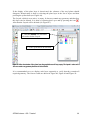
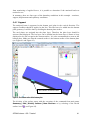
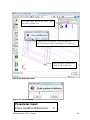
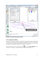
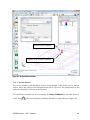
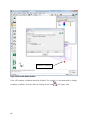
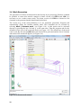
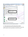
The finite element analysis is started by the clicking on the icon
command Calculate | Calculate. After selecting this command, the program will start to
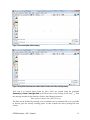
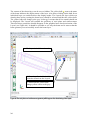
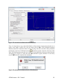
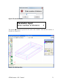
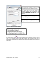
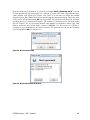
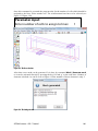
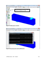
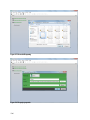
generate the input files for each step of the non-linear analysis. This process is indicated by
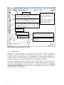
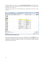
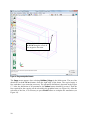
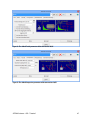
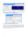
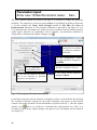
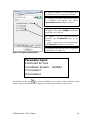
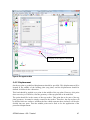
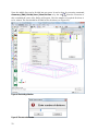
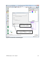
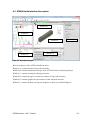
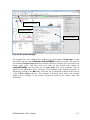
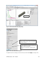
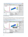
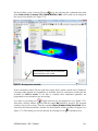
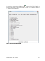
the dialog box (see Figure 137). And then the ATENA Studio window will appear and
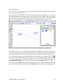
analysis will be in progress (see Figure 138).
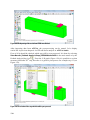
Figure 137: The initializing of the analysis
If the creation of the geometrical model and definition of the boundary conditions were
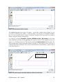
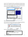
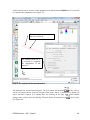
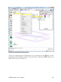
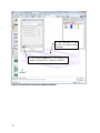
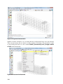
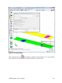
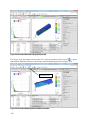
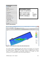
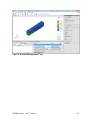
done right, the static analysis should be finished in one minute. Then in the Geometry
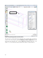
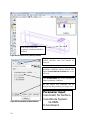
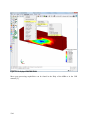
window it is possible to see that the loading steel plate strangely distorted and shifted (see
Figure 139) by the applied loads. Due to that the structure could not be calculated
correctly. It is because there is no connection defined between the concrete beam and the
steel plates. Program does not automatically detect possible contact between volumes.
Contacts have to be added manually by boundary special conditions.
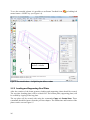
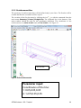
Therefore, it is necessary to return back to GiD graphical interface and defined fixed
contacts. ATENA Studio can be simply closed without any savings of data and then it is
necessary to return back to the GiD graphical interface and define the missing contacts.
It should be noted that this problem is a direct consequence of the modelling approach that
was chosen in the previous section.
In this tutorial, the geometry is created by three individual and separated volumes. In such
a case contacts have to be added manually. If the corresponding surfaces of the steel plates
would be also parts of the geometry of the beam, all parts of the structure would be
connected and no special condition would have to be defined.
104