1
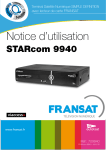
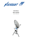
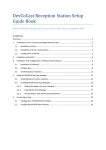
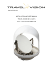
GB
Operating Instructions
SAT-Finder plus
Contents
1.
1.1
1.2
1.3
1.4
Getting started
Package contents
Safety information
Connecting the SAT-Finder plus
Start-up process
2.
2.1.
2.2.
2.3.
Searching and finding
Automatic search
Manual search
RESET
3.
3.1.
3.2.
3.3.
3.4.
LED displays
LEVEL
QUALITY
MODE
SATELLITES
4. Appendix
4.1. Updating the SAT-Finder plus
4.2. Footprints / reception areas for the satellites
Connection example
Receiver
Multischalter
te
upda
COM
SAT Finder plus
GW 9000
PC
1. Getting started
1.1 Package contents
SAT-Finder plus
Connection cable 70 cm
Carrying strap
Quick reference guide (in 16 languages)
Operating instructions
1.2 Safety information
Before using the unit for the first time, read and follow the safety instructions carefully!
Be sure to think of your own safety when setting up your system (slippery roof, risk of falling).
Do not use the SAT-Finder plus if there is visible damage to the unit or the connecting cables. Be
careful that the cables do not pose a risk of tripping.
Make sure that you don’t trap or crush the connecting cables.
The antenna used must be earthed.
The SAT-Finder plus is only designed for the short-term set up of a satellite system. Continuous use
can damage the unit.
The unit must not be used in the immediate vicinity of inflammable materials.
Only have repairs carried out by our qualified service personnel. Attempts to open or repair the
unit yourself will void the warranty.
1.3 Connecting the SAT-Finder plus
Using the coax cable supplied with the unit, connect the socket on the SAT-Finder plus marked ‘LNB’
directly to your LNB. Then connect a power source to the ‘REC’ socket, either via a DVB-receiver,
multiswitch or the SCHWAIGER GW9000.
Only tighten the nuts by hand.
Important:
As some receivers do not correctly conform to the norm for H/V switching voltages, we recommend
that if you have old or especially long cables to use the GW9000 DC splitter for power supply
purposes, to ensure that the SAT-Finder plus has sufficient power.
Suitable LNB types:
• Single-LNB
• Twin-LNB
• Quad / Quattro-Switch - LNB
• Quattro-LNB
If the SAT-Finder plus is to be connected directly to a Quattro-LNB, use the following table to
connect it to one of the four LNB outputs so that the desired satellite can be identified.
Horizontal High Band (H/H)
Orbit positions from east to west
position
53
42
39
28
26
23
19
16
13
7
5
1
4
5
7
8
30
identifiable
-
x
o
x
x
x
x
-
x
-
x
x
-
x
x
-
x
Horizontal Low Band (H/L)
Orbit positions from east to west
position
53
42
39
28
26
23
19
16
13
7
5
1
4
5
7
8
30
identifiable
-
o
x
x
x
o
o
-
x
x
-
x
x
x
o
x
o
Vertical High Band (V/H)
Orbit positions from east to west
position
53
42
39
28
26
23
19
16
13
7
5
1
4
5
7
8
30
identifiable
-
-
-
-
-
-
-
-
-
-
-
-
-
-
-
-
-
Vertical Low Band (V/L)
Orbit positions from east to west
position
53
42
39
28
26
23
19
16
13
7
5
1
4
5
7
8
30
identifiable
x
-
-
-
-
-
-
x
-
-
-
-
-
-
-
-
-
x clearly identifiable
o still identifiable
- not identifiable
1.4 Start-up process
After the power source has been connected, the Power-LED will show the SAT-Finder plus’s power
status and the boot sequence will begin.
After approx. 3-5 seconds the unit’s firmware has been loaded into its RAM memory and component
initialisation will begin. Subsequently, all LEDs will light up briefly and the SAT-Finder plus is ready
for use.
The entire start-up process takes around 7 seconds.
2. Searching and finding
2.1 Automatic satellite search
When the red Power-LED is on, the SAT-Finder plus is ready for use and you can align the satellite
dish. It should be turned or adjusted in small steps otherwise you might easily miss a satellite, just
like with analogue SAT-finders.
Turn the satellite dish vertically until the LEVEL LEDs light up.
When a sufficiently strong signal is received (when 3 LEDs are “on”), the SAT-Finder plus will analyse
the transponder found – this is shown by the MODE-LED flashing.
If the quality of the signal is very low (up to 3 LEDs “on”), continue to turn the satellite dish further
until sufficient signal quality, approx. 4-6 LEDs, is shown. As soon as the SAT-Finder plus has recognised the satellite, this will be indicated by a green LED on the satellite summary and the quality of
the signal will be shown by the QUALITY-LEDs lighting up.
If due to discrepancies in the data the satellite cannot be precisely identified, the LED for the satellite
assumed to be the correct one based on the data received so far will continue to flash.
The SAT-Finder plus will then switch to wait mode, and if it is the satellite you were searching for
you can start with the fine tuning of the satellite dish.
If a satellite has been identified, but it is not the one you were looking for, then you now know
which orbit position/direction the satellite dish is pointing in, making it possible to target the desired
satellite. To do this, turn the satellite dish in the corresponding direction until the SAT-Finder plus
switches back to automatic search mode and starts to search for a satellite signal again.
Repeat this procedure until you have found the desired satellite.
2.2 Manual search / satellite preselection
Manual search allows a preselection of satellites that are located close to each other.
By pressing the left “A” button once the currently active LED will move on one step, thus selecting
the next satellite. The satellites you can select are: 8°W Telecom2D, 7°W Nilesat, 5°W Atlanticbird
and 4°W Amos.
Turn the satellite dish vertically until the LEVEL LEDs light up.
When a sufficiently strong signal is received (when 3 LEDs are “on”), the SAT-Finder plus will analyse
the transponder found – that is shown by the MODE-LED flashing.
If the quality of the signal is very low (up to 3 LEDs “on”), continue to turn the satellite dish further
until sufficient signal quality, approx. 4-6 LEDs, is shown. As soon as the SAT-Finder plus has recognised the satellite, this will be indicated by a green LED on the satellite summary and the quality of
the signal will be shown by the QUALITY-LEDs lighting up.
If due to discrepancies in the data the satellite cannot be precisely identified, the LED for the satellite
assumed to be the correct one based on the data received so far will continue to flash.
The SAT-Finder plus will then switch to wait mode, and if it is the satellite you were searching for
you can start with the fine tuning of the Satellite dish.
If you press the “B” button the SF9000 will switch back to automatic search.
2.3 Reset
If you press both buttons together and hold them down for approx. 5 seconds, this will reset the
SAT-Finder plus.
3. LED displays
3.1 LEVEL (signal strength)
Signal strength is displayed to the user via 8 LEDs. Each LED can either be “off”, “flashing slowly”,
“flashing quickly” or “on”, giving a total of 24 stages providing as fine a graduation as possible
for signal strength.
3.2 QUALITY (signal quality)
Signal quality is displayed to the user via 8 LEDs.
3.3 MODE (mode of operation)
Shows the operating mode, “flashing” or “on”.
3.4 Satellite display
Satellite display works similarly to the display of operating/search mode, using the status “off”,
“flashing” and “on”, with meanings as shown in the following table:
MODE- LED
LED for the
respective
satellite
Meaning
„off“
„off“
The SAT-Finder plus hasn’t locked on to a transponder.
„flashing“
„off“
The SAT-Finder plus has locked onto a transponder, but no satellite has been
identified yet or not enough data/information has been received yet.
„flashing“
„flashing“
The SAT-Finder plus has locked onto a transponder and is analysing its data.
Based on the data analysed so far the SAT-Finder plus assumes that the satellite
dish is aligned with the satellite shown by the LED.
„on“
„on“
The SAT-Finder plus has locked onto a transponder, all necessary data has
been received and processed.
Based on the information received the satellite will by shown by its corresponding LED.
„on“
„flashing“
Special case:
The SAT-Finder plus has locked onto a transponder and analysed all the data
received. However, either not all the necessary data could be received or there
were discrepancies in the information received.
The SAT-Finder plus will show by LED what it assumes to be the correct satellite
based on the data received.
„on“
„off“
Special case:
The SAT-Finder plus has, as in the previous case, completed analysis of the
data. Based on the data, either no satellite could be identified or the satellite
is one that is not included on the SAT-Finder plus display.
In this case the unit will try to tune to other transponders in order to start a
new attempt at identifying the satellite.
4. Appendix
4.1 Updating the SAT-Finder plus with the separately available software kit CKA9000
The SAT-Finder plus identifies satellites using a range of data, which includes satellite tables.
Because satellite operators and media organisations may make changes, the SAT-Finder plus is
updateable. The SAT-Finder plus updater is a piece of software for Windows that carries out this
task, enabling you to keep both the firmware and the satellite tables up to date at all times (or go
to www.schwaiger.de).
Connection
Connect the SAT-Finder plus to the power supply (receiver, multiswitch or GW9000). The transfer
cable in the SW-Kit provides a connection between the SAT-Finder plus (update socket) and the PC
via the serial bus (COM-Port).
After the program starts, you will see the following screen:
Explanation of the functions
- SAT-Finder plus
With the aid of the <Firmware Version?> and <SatTables Version?> buttons you can find out the
current version numbers of the firmware and satellite tables stored in the SAT-Finder plus.
- Options
When the option ‘update Firmware?’ is active, an update of the SAT-Finder plus system software
is carried out.
When the option ‘update SatTables?’ is active, an update of the satellite identification data will be
carried out.
If both options are active, first the firmware is updated followed by the satellite data.
- Update
The buttons <select Firmware> and <select SatTables> open a Windows dialogue box to enter the
path and file details of the respective files.
The <help> button opens a dialogue box giving information on the options and buttons.
<start update> launches the SAT-Finder plus update.
You can press the <exit>-button to leave the program.
Carrying out the updates
After the program has started, you can select the desired update in the ‘Options’ field. This selection
will activate the corresponding button in the ‘Update’ field (<select Firmware> or <select SatTables>)
and the files can be selected
Under <Target connected to..> select the COM-port on your PC (1 or 2) that the SAT-Finder plus
is connected to.
Pressing the <start update> button launches the update. The program prepares the SAT-Finder
plus for the update then reboots the system. In the program’s status bar, the message “waiting for
bootloader” will be displayed.
Once the SAT-Finder plus has been recognised and is in update mode, the transfer of the selected
file will begin. The status message will change to “transmitting image...” and the progress of the
transfer is shown in the status bar.
10
When transfer is complete and if only one update was selected, the status will change to “upload
complete”.
If both updates are to be carried out, the status bar will display “wait for second update...”. In both
cases the SAT-Finder plus saves the transferred files to its flash memory and then reboots.
After updating, the SAT-Finder plus will start in normal operating mode and the update is complete.
4.2 Footprints / reception areas for the satellites
Every satellite, depending on the type and number of its antennae, its performance etc., transmits
to a certain area of the earth’s surface. These areas are known as footprints and denote the
geographical area within which the satellite can be received. In areas on the periphery, sometimes
satellite dishes with a diameter of 85 to >150 cm are required (see EIRP table). On the following
pages the footprints are listed for which the SAT-Finder plus is configured, and they represent the
unit’s theoretical operational area.
Note:
The footprints were obtained from http://www.lyngsat.com and are subject to the copyrights of
http://www.lyngsat.com.
EIRP / diameter of the satellite dish
EIRP [dBW]
>45
45
44
43
42
41
40
39
min. D [cm]
<65
65-85
75-95
85-100
95-120
105-135
120-150
135-170
Footprints that are contained within another footprint, or are very similar to each other, are not
included in the list.
11
53°East - EXPRESS AM22
42° East - TÜRKSAT
39° East - HELLAS SAT 2
12
28,5° East - EUROBIRD
26° East - ARABSAT
23,5° East - ASTRA 1D + 3A
13
19,2° East - ASTRA 1E - 2C
16° East - EUTELSAT W2
13° East - HOTBIRD
14
7° East - EUTELSAT W3
5° East - SIRIUS
15
1° West - THOR
4° West - AMOS
16
5° West - ATLANTIC BIRD
7° West - NILESAT
8° West - ATLANTIC BIRD 2
17
30° West - HISPASAT
18
4.3 Guarantee conditions
There is a statutory guarantee of 2 years. During this period, any damage caused by manufacturing
or material faults will be repaired free of charge. Our guarantee does not apply to natural wear and
tear, expendable parts, shipping damage and, furthermore, any damage caused by not following
the operating instructions or by unqualified installation.
The protective elements that are destroyed when triggered by a power surge and damage caused
by connecting unsuitable devices to the unit are also excluded from the guarantee. When claiming
under guarantee, the date of purchase must be confirmed by enclosing the invoice, delivery receipt
or similar documentation.
4.4 Service information
At SCHWAIGER, customer satisfaction is of the highest priority.
Should you have any questions, suggestions or problems regarding your SCHWAIGER product, please
use the contact address below.
Service-Hotline: +49 (0)9101 702-299
Service-Fax: +49 (0)9101 702-121
[email protected]
www.schwaiger.de
19
Christian Schwaiger GmbH
Würzburger Straße 17
90579 Langenzenn, Germany
20