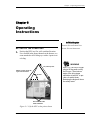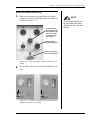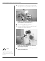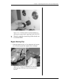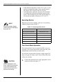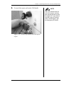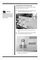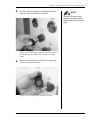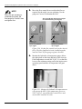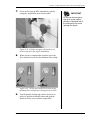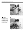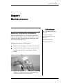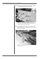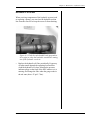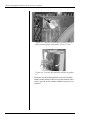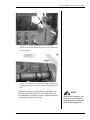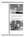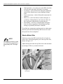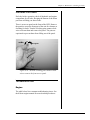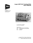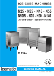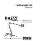
1
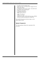
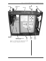
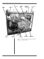
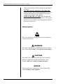
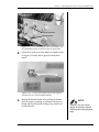
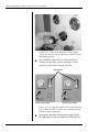
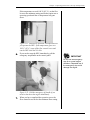
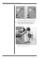
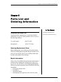
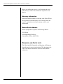
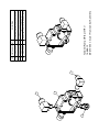
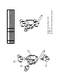
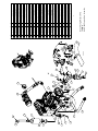
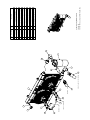
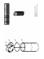
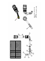
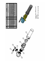
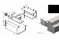
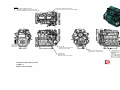
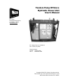
Tandem Pump Offshore
Hydraulic Power Unit
User’s Manual
E.H. Wachs
600 Knightsbridge Parkway
Lincolnshire, IL 60069
www.ehwachs.com
E.H. Wachs Part No. 14-MAN-12
Rev. 2-0709, July 2009
Revision History:
Original October 2008
Rev. 1
November 2008
Copyright © 2009 E.H. Wachs. All rights reserved.
This manual may not be reproduced in whole or in part
without the written consent of E.H. Wachs.
Tandem Pump Offshore Hydraulic Power Unit User’s Manual
Part No. 14-MAN-12, Rev. 2-0709
E.H. Wachs
Table of Contents
Table of Contents
Chapter 1: About the Tandem Pump Power Unit . . . . . . . . . . . . . . . . . . . . . . . . . . . . . . . . . . . 1
Purpose of This Manual . . . . . . . . . . . . . . . . . . . . . . . . . . . . . . . . . . . . . . . . . . . . . . . . . . . . . . . . . 1
How to Use The Manual . . . . . . . . . . . . . . . . . . . . . . . . . . . . . . . . . . . . . . . . . . . . . . . . . . . . . . . . . 1
Symbols and Warnings . . . . . . . . . . . . . . . . . . . . . . . . . . . . . . . . . . . . . . . . . . . . . . . . . . . . . . . . . . 2
Manual Updates and Revision Tracking. . . . . . . . . . . . . . . . . . . . . . . . . . . . . . . . . . . . . . . . . . . . . 3
Equipment Description . . . . . . . . . . . . . . . . . . . . . . . . . . . . . . . . . . . . . . . . . . . . . . . . . . . . . . . . . . 3
System Specifications . . . . . . . . . . . . . . . . . . . . . . . . . . . . . . . . . . . . . . . . . . . . . . . . . . . . . . . . 3
System Components . . . . . . . . . . . . . . . . . . . . . . . . . . . . . . . . . . . . . . . . . . . . . . . . . . . . . . . . . 4
Hydraulic Fluid Overview . . . . . . . . . . . . . . . . . . . . . . . . . . . . . . . . . . . . . . . . . . . . . . . . . . . . . . . 7
Specifications . . . . . . . . . . . . . . . . . . . . . . . . . . . . . . . . . . . . . . . . . . . . . . . . . . . . . . . . . . . . . . 8
Chapter 2: Safety . . . . . . . . . . . . . . . . . . . . . . . . . . . . . . . . . . . . . . . . . . . . . . . . . . . . . . . . . . . . 11
Operator Safety . . . . . . . . . . . . . . . . . . . . . . . . . . . . . . . . . . . . . . . . . . . . . . . . . . . . . . . . . . . . . . . 11
Safety Symbols . . . . . . . . . . . . . . . . . . . . . . . . . . . . . . . . . . . . . . . . . . . . . . . . . . . . . . . . . . . . 12
Protective Equipment Requirements . . . . . . . . . . . . . . . . . . . . . . . . . . . . . . . . . . . . . . . . . . . 13
Safety Procedures . . . . . . . . . . . . . . . . . . . . . . . . . . . . . . . . . . . . . . . . . . . . . . . . . . . . . . . . . . 13
Safety Labels. . . . . . . . . . . . . . . . . . . . . . . . . . . . . . . . . . . . . . . . . . . . . . . . . . . . . . . . . . . . . . . . . 15
Chapter 3: Operating Instructions . . . . . . . . . . . . . . . . . . . . . . . . . . . . . . . . . . . . . . . . . . . . . . 17
Setting Up the Power Unit . . . . . . . . . . . . . . . . . . . . . . . . . . . . . . . . . . . . . . . . . . . . . . . . . . . . . . 17
Start-Up and Operation . . . . . . . . . . . . . . . . . . . . . . . . . . . . . . . . . . . . . . . . . . . . . . . . . . . . . . . . . 23
Engine Starting Tips . . . . . . . . . . . . . . . . . . . . . . . . . . . . . . . . . . . . . . . . . . . . . . . . . . . . . . . . 25
Operating Checks . . . . . . . . . . . . . . . . . . . . . . . . . . . . . . . . . . . . . . . . . . . . . . . . . . . . . . . . . . 26
Two-Circuit Mode Operation . . . . . . . . . . . . . . . . . . . . . . . . . . . . . . . . . . . . . . . . . . . . . . . . . 26
Combined-Circuit Mode Operation . . . . . . . . . . . . . . . . . . . . . . . . . . . . . . . . . . . . . . . . . . . . 32
Chapter 4: Maintenance. . . . . . . . . . . . . . . . . . . . . . . . . . . . . . . . . . . . . . . . . . . . . . . . . . . . . . . 37
Disabling the Starter for Service. . . . . . . . . . . . . . . . . . . . . . . . . . . . . . . . . . . . . . . . . . . . . . . . . . 37
Hydraulic System . . . . . . . . . . . . . . . . . . . . . . . . . . . . . . . . . . . . . . . . . . . . . . . . . . . . . . . . . . . . . 39
Cooler . . . . . . . . . . . . . . . . . . . . . . . . . . . . . . . . . . . . . . . . . . . . . . . . . . . . . . . . . . . . . . . . . . . 43
Engine Maintenance and Service . . . . . . . . . . . . . . . . . . . . . . . . . . . . . . . . . . . . . . . . . . . . . . . . . 43
Fluid Levels . . . . . . . . . . . . . . . . . . . . . . . . . . . . . . . . . . . . . . . . . . . . . . . . . . . . . . . . . . . . . . 45
Air Filters . . . . . . . . . . . . . . . . . . . . . . . . . . . . . . . . . . . . . . . . . . . . . . . . . . . . . . . . . . . . . . . . 45
Spark Arrestor. . . . . . . . . . . . . . . . . . . . . . . . . . . . . . . . . . . . . . . . . . . . . . . . . . . . . . . . . . . . . 47
Air Starter System. . . . . . . . . . . . . . . . . . . . . . . . . . . . . . . . . . . . . . . . . . . . . . . . . . . . . . . . . . . . . 47
Starter Motor Oiler . . . . . . . . . . . . . . . . . . . . . . . . . . . . . . . . . . . . . . . . . . . . . . . . . . . . . . . . . 48
Checking for Leaks . . . . . . . . . . . . . . . . . . . . . . . . . . . . . . . . . . . . . . . . . . . . . . . . . . . . . . . . . . . . 49
Troubleshooting . . . . . . . . . . . . . . . . . . . . . . . . . . . . . . . . . . . . . . . . . . . . . . . . . . . . . . . . . . . . . . 49
Engine . . . . . . . . . . . . . . . . . . . . . . . . . . . . . . . . . . . . . . . . . . . . . . . . . . . . . . . . . . . . . . . . . . . 49
Hydraulic System . . . . . . . . . . . . . . . . . . . . . . . . . . . . . . . . . . . . . . . . . . . . . . . . . . . . . . . . . . 52
E.H. Wachs
Part No. 14-MAN-12, Rev. 2-0709
i
Tandem Pump Offshore Hydraulic Power Unit User’s Manual
Chapter 5: Parts List and Ordering Information . . . . . . . . . . . . . . . . . . . . . . . . . . . . . . . . . .
Ordering Information . . . . . . . . . . . . . . . . . . . . . . . . . . . . . . . . . . . . . . . . . . . . . . . . . . . . . . . . . .
Ordering Replacement Parts . . . . . . . . . . . . . . . . . . . . . . . . . . . . . . . . . . . . . . . . . . . . . . . . . .
Repair Information . . . . . . . . . . . . . . . . . . . . . . . . . . . . . . . . . . . . . . . . . . . . . . . . . . . . . . . . .
Warranty Information . . . . . . . . . . . . . . . . . . . . . . . . . . . . . . . . . . . . . . . . . . . . . . . . . . . . . . .
Return Goods Address . . . . . . . . . . . . . . . . . . . . . . . . . . . . . . . . . . . . . . . . . . . . . . . . . . . . . .
Drawings and Parts Lists . . . . . . . . . . . . . . . . . . . . . . . . . . . . . . . . . . . . . . . . . . . . . . . . . . . . . . .
ii
Part No. 14-MAN-12, Rev. 2-0709
55
55
55
55
56
56
56
E.H. Wachs
Chapter 1, About the Tandem Pump Power Unit
Chapter 1
About the Tandem
Pump Power Unit
In This Chapter
PURPOSE OF THIS MANUAL
PURPOSE OF THIS MANUAL
HOW TO USE THE MANUAL
This manual explains how to operate and maintain the tandem pump hydraulic power unit. It includes instructions for
set-up, operation, and maintenance. It also contains parts
lists and diagrams to help you order replacement parts and
perform user-serviceable repairs.
SYMBOLS AND WARNINGS
MANUAL UPDATES AND
REVISION TRACKING
EQUIPMENT DESCRIPTION
HYDRAULIC FLUID OVERVIEW
HOW TO USE THE MANUAL
This manual is organized to help you quickly find the information you need. Each chapter describes a specific topic on
using or maintaining the equipment.
Throughout this manual, refer
to this column for warnings,
cautions, and notices with
supplementary information.
Each page is designed with two columns. This large column
on the inside of the page contains instructions and illustrations. Use these instructions to operate and maintain the
equipment.
The narrower column on the outside contains additional
information such as warnings, special notes, and definitions. Refer to it for safety notes and other information.
E.H. Wachs
Part No. 14-MAN-12, Rev. 2-0709
1
Tandem Pump Offshore Hydraulic Power Unit User’s Manual
SYMBOLS AND WARNINGS
The following symbols are used throughout this manual to
indicate special notes and warnings. They appear in the outside column of the page, next to the section they refer to.
Make sure you understand what each symbol means, and
follow all instructions for cautions and warnings.
WARNING
A WARNING alert with the
safety alert symbol indicates
a potentially hazardous situation that could result in serious injury or death.
This is the safety alert symbol. It is used
to alert you to potential personal injury
hazards. Obey all safety messages that
follow this symbol to avoid possible
injury or death.
CAUTION
A CAUTION alert with the
safety alert symbol indicates
a potentially hazardous situation that could result in
minor or moderate injury.
CAUTION
A CAUTION alert with the
damage alert symbol indicates a situation that will
result in damage to the
equipment.
This is the equipment damage alert
symbol. It is used to alert you to potential equipment damage situations.
Obey all messages that follow this symbol to avoid damaging the equipment or
workpiece on which it is operating.
IMPORTANT
An IMPORTANT alert with
the damage alert symbol indicates a situation that may
result in damage to the
equipment.
2
Part No. 14-MAN-12, Rev. 2-0709
E.H. Wachs
Chapter 1, About the Tandem Pump Power Unit: Manual Updates and Revision Tracking
NOTE
NOTE
This symbol indicates a user note. Notes
provide additional information to supplement the instructions, or tips for easier
operation.
A NOTE provides supplementary information or operating tips.
MANUAL UPDATES AND REVISION TRACKING
Occasionally, we will update manuals with improved operation or maintenance procedures, or with corrections if necessary. Revised manuals will be available for customers.
When a manual is revised, we will update the revision history on the title page and at the bottom of the pages.
You may have factory service or upgrades performed on the
equipment. If this service changes any technical data or
operation and maintenance procedures, we will include a
revised manual when we return the equipment to you.
Current versions of E.H.
Wachs Company manuals
are also available in PDF format. You can request an
electronic copy of this manual
by emailing customer service
at [email protected].
EQUIPMENT DESCRIPTION
The tandem pump hydraulic power unit is designed to operate with either two independent hydraulic circuits, providing 8 gpm and 16 gpm flow, or with one combined circuit
providing up to 24 gpm flow. A flow mode lever on the system control panel switches the unit between independent
and combined flow.
System Specifications
•
•
•
•
•
•
•
•
Dual pump providing 16 gpm (60 l/m)and 8 gpm (30 l/
m) hydraulic circuits at 2200 psi (152 bar)
Combined flow mode for up to 24 gpm (90 l/m)
Kubota V2203 diesel engine (48.1 HP @ 2800 rpm)
Air start (3/4”-14 taper pipe thread per ANSI B1.20.1)
Dry air cleaner
16 gallon (61 liter) diesel fuel tank
ATEX-rated spark arrestor/muffler
Safety air shut-off/overspeed valve
E.H. Wachs
Part No. 14-MAN-12, Rev. 2-0709
3
Tandem Pump Offshore Hydraulic Power Unit User’s Manual
•
•
•
•
•
•
•
50 gallon (189 liter) hydraulic tank
Inline flow meters—one each circuit: 30 gpm (114 l/m)
and 10 gpm (38 l/m)
0-3000 psi (207 bar) pressure gauges—one each circuit
Steel tubular frame with drip pan
Lifting eyes at 4 corners
Approximate dimensions:
height: 60.25” (153 cm)
length: 72” (183 cm)
width: 40” (102 cm)
Approximate weight: 1920 lbs (864 kg) empty; 2400 lbs
(1082 kg) with fuel and hydraulic oil tanks full.
For detailed information on the diesel engine, see the
Kubota engine manual.
System Components
The following figures illustrate the components of the
power unit.
4
Part No. 14-MAN-12, Rev. 2-0709
E.H. Wachs
Chapter 1, About the Tandem Pump Power Unit: Equipment Description
Lift eyes
Hydraulic oil
reservoir
Hydraulic oil
cooler
Exhaust
pipe
Fuel cap
Hydraulic oil temperature
and level gauge
Drain
plug
Control
panel
Lift
eyes
Diesel
engine
Figure 1-1. The photo shows the front view of the
HPU, with major components illustrated.
E.H. Wachs
Part No. 14-MAN-12, Rev. 2-0709
5
Tandem Pump Offshore Hydraulic Power Unit User’s Manual
Engine
radiator
Engine air
filter
Diesel
engine
Diesel fuel
tank
Hydraulic
suction line
Hydraulic
reservoir
fill cap
Hydraulic
connectors
Hydraulic oil
temperature
and level gauge
Air starter
connection
Hydraulic oil
cooler
Hydraulic oil
drain valve
Figure 1-2. The photo shows the components visible
from the rear side of the HPU.
6
Part No. 14-MAN-12, Rev. 2-0709
E.H. Wachs
Chapter 1, About the Tandem Pump Power Unit: Hydraulic Fluid Overview
Engine oil
pressure
Instruction
label
Engine
temperature
Throttle
Engine shut-off
Engine starter
Emergency
shut-off
Circuit #1
hydraulic
pressure
Circuit #2 hydraulic
pressure
Circuit #2
hydraulic flow
Circuit #1
hydraulic flow
NOTE: In combined
circuit mode, the
Circuit #2 gauges
register the combined circuit pressure and flow.
Circuit #1
flow control
Circuit #2
flow control
Front service panel—turn and
release pins to remove the panel
Flow mode lever
Down = combined circuit mode
Right = two-circuit mode
Figure 1-3. HPU control panel. When the flow mode
lever is in the two-circuit position, both hydraulic circuits are operating. When the lever is in combined circuit position, only Circuit #2 is operating.
HYDRAULIC FLUID OVERVIEW
The performance and life expectancy of your Wachs
hydraulic power unit largely depends on the hydraulic fluid
used. One of the most important fluid characteristics is viscosity—the “thickness” of the fluid. Viscosity choice is a
compromise; the fluid must be thin enough to flow easily
but thick enough to seal and lubricate mating surfaces.
E.H. Wachs
Part No. 14-MAN-12, Rev. 2-0709
7
Tandem Pump Offshore Hydraulic Power Unit User’s Manual
Fluid temperature greatly affects its viscosity. As the fluid
warms it gets thinner (lower viscosity) and as it cools it gets
thicker (higher viscosity). Your Wachs hydraulic power unit
has an optimal viscosity range which is listed in the following “Specifications” section. Ambient temperatures, operating loads, and many other contributors affect the fluid’s
viscosity. A hydraulic fluid for use in 0° F (-18° C) may not
work adequately in 100° F (38° C).
Cleanliness of the hydraulic oil is extremely important for
the life expectancy of the hydraulic components. Wachs recommends the fluid used to be maintained at ISO Cleanliness
Code 19/17/14 per SAE J1165. Establishing a fluid maintenance schedule is the best way of meeting viscosity and
fluid cleanliness requirements.
Premium grade petroleum-based hydraulic fluids will provide the best performance for your Wachs hydraulic power
unit. These fluids typically contain anti-wear additives, rust
inhibitors, anti-foaming agents, and oxidation inhibitors.
Premium grade fluids carry an ISO VG rating. Synthetic
fluids, fluids with viscosity index improvers (ATF or multiviscosity oil), and SAE grade oils maybe used, but their use
will require more frequent maintenance intervals and application review in your system.
Specifications
NOTE: These specifications are guidelines for the hydraulic
power unit only. Your hydraulic tools may require more
stringent requirements. For example, your tool may limit
the operating viscosity range to 85-450 SSU (16 - 95 CSt).
Always consult your hydraulic tool manufacturer for
hydraulic fluid guidelines.
Table 1: Viscosity Data
8
Units
Minimum
Continuous
Viscosity
Optimum
Operating
Viscosity Range
Maximum
Viscosity at
Pressure
Viscosity Range
Requiring <50%
Outlet Pressure
SSU
41
55-190
450
470-5000
CSt
9
16-40
95
100-1000
Part No. 14-MAN-12, Rev. 2-0709
E.H. Wachs
Chapter 1, About the Tandem Pump Power Unit: Hydraulic Fluid Overview
Table 2: Hydraulic Fluid Specifications
Specification
Range
Pour Point
-10° F (-23° C) min.
Flash Point (ASTM D-92)
340° F (171° C) min.
Emulsion Test (ASTM D-1401)
30 minutes min.
Oxidation Test (ASTM D-943)
1000 hours min.
Rust Inhibition Test (ASTM D-665 A & B)
Pass - No Rust
Wear Test (ASTM D-2882)
60 mg maximum
The following are recommended hydraulic fluids for typical
industrial environments:
•
•
•
•
Citgo AW (anti-wear) 32
Shell Tellus T-32
Shell Tellus S-46
Chevron AW-32
E.H. Wachs
Part No. 14-MAN-12, Rev. 2-0709
9
Tandem Pump Offshore Hydraulic Power Unit User’s Manual
10
Part No. 14-MAN-12, Rev. 2-0709
E.H. Wachs
Chapter 2, Safety
Chapter 2
Safety
The E.H. Wachs Company takes great pride in designing
and manufacturing safe, high-quality products. We make
user safety a top priority in the design of all our products.
In This Chapter
OPERATOR SAFETY
SAFETY LABELS
Read this chapter carefully before operating the hydraulic
power unit. It contains important safety instructions and
recommendations.
OPERATOR SAFETY
Follow these guidelines for safe operation of the equipment.
•
•
•
•
READ THE OPERATING MANUAL. Make sure
you understand all setup and operating instructions
before you begin.
INSPECT MACHINE AND ACCESSORIES.
Before starting the machine, look for loose bolts or
nuts, leaking lubricant, rusted components, and any
other physical conditions that may affect operation.
Properly maintaining the machine can greatly decrease
the chances for injury.
ALWAYS READ PLACARDS AND LABELS. Make
sure all placards, labels, and stickers are clearly legible
and in good condition. You can purchase replacement
labels from E.H. Wachs Company.
KEEP CLEAR OF MOVING PARTS. Keep hands,
arms, and fingers clear of all rotating or moving parts.
E.H. Wachs
Part No. 14-MAN-12, Rev. 2-0709
Look for this symbol throughout the
manual. It indicates
a personal injury
hazard.
11
Tandem Pump Offshore Hydraulic Power Unit User’s Manual
•
•
Always turn machine off before doing any adjustments
or service.
SECURE LOOSE CLOTHING AND JEWELRY.
Secure or remove loose-fitting clothing and jewelry, and
securely bind long hair, to prevent them from getting
caught in moving parts of the machine.
KEEP WORK AREA CLEAR. Keep all clutter and
nonessential materials out of the work area. Only people
directly involved with the work being performed should
have access to the area.
Safety Symbols
This icon is displayed with any safety alert that indicates a
personal injury hazard.
WARNING
This safety alert indicates a potentially hazardous situation
that, if not avoided, could result in death or serious injury.
CAUTION
This safety alert, with the personal injury hazard symbol,
indicates a potentially hazardous situation that, if not
avoided, could result in minor or moderate injury.
NOTICE
This alert indicates a situation that, if not avoided, will
result in damage to the equipment.
12
Part No. 14-MAN-12, Rev. 2-0709
E.H. Wachs
Chapter 2, Safety: Operator Safety
IMPORTANT
This alert indicates a situation that, if not avoided, may
result in damage to the equipment.
Protective Equipment Requirements
WARNING
Always wear impact resistant eye protection while operating or working near
this equipment.
For additional information on eye and face protection, refer
to Federal OSHA regulations, 29 Code of Federal Regulations, Section 1910.133., Eye and Face Protection and
American National Standards Institute, ANSI Z87.1, Occupational and Educational Eye and Face Protection. Z87.1 is
available from the American National Standards Institute,
Inc., 1430 Broadway, New York, NY 10018.
CAUTION
Personal hearing protection is recommended when operating or working near
this equipment.
Hearing protectors are required in high noise areas, 85 dBA
or greater. The operation of other tools and equipment in the
area, reflective surfaces, process noises, and resonant structures can increase the noise level in the area. For additional
information on hearing protection, refer to Federal OSHA
regulations, 29 Code of Federal Regulations, Section
1910.95, Occupational Noise Exposure and ANSI S12.6
Hearing Protectors.
Safety Procedures
All safety requirements listed below are those generally
applicable to hydraulically-powered machinery but are not
intended to be an all-inclusive list. They are intended as
guidelines only and will assist in avoiding risk of injury
when followed by qualified, experienced personnel. These
E.H. Wachs
Part No. 14-MAN-12, Rev. 2-0709
13
Tandem Pump Offshore Hydraulic Power Unit User’s Manual
precautions should be included in the comprehensive safety
program for the particular machinery, equipment, plant or
process and overseen by personnel capable of analyzing any
hazards associated with operating and maintaining the
equipment.
WARNING
Many types of
machinery have
parts that may
start moving as soon as the
hydraulic circuit is filled and
pressurized. This could result
in injury to personnel or damage to machinery.
1. Return all movable parts of the machinery being operated to their normal startup condition, if possible,
before starting unit.
2. Be sure all personnel, product, etc. are clear of
machinery before starting hydraulic unit.
3. Check to make sure any hydraulic connections which
may have been removed, replaced or disconnected
during shut down have been reconnected securely
before starting hydraulic unit.
4. Before starting the unit, perform all equipment checks
described at the beginning of the operating instructions in Chapter 3.
5. If there are tools or machinery being operated by the
HPU that may move when hydraulic flow or pressure
are turned off or turned on, block or lock these parts in
position before shutting down the hydraulic unit.
WARNING
Make sure all personnel are clear
from the machinery being operated before
shutting down the HPU.
6. Shut down the hydraulic unit and relieve pressure
from all pressurized accumulators, actuators and lines
before removing, tearing down or performing maintenance on any remotely-located actuators, hoses, filters, valves, piping, etc.
7. Any personnel observing or working on or adjacent to
hydraulically-powered equipment must never place
themselves in a location or position that could produce
an injury in the event of:
•
•
•
•
14
a hydraulic line failure either with the unit running or
shut down;
pump or motor failure or;
pin-hole leaks in hoses or fittings;
movement of machine components during normal operation or resulting from a component malfunction or failure.
Part No. 14-MAN-12, Rev. 2-0709
E.H. Wachs
Chapter 2, Safety: Safety Labels
8. Do not inspect hoses and fittings for leaks using your
bare hands. A pin-hole leak can inject hydraulic fluid
through the skin, with the potential for serious injury.
9. Avoid locating equipment in any environment for
which it was not designed and which may create a
dangerous operating condition such as an explosive
atmosphere (e.g., gas, dust), high heat (e.g., molten
metal, furnace), chemicals, extreme moisture, etc.
WARNING
The injection of
hydraulic fluid
under the skin can
cause serious injury and
even result in death. If an
injection injury occurs, seek
medical treatment immediately.
10. Avoid bodily contact with hydraulic fluids. Some
hydraulic fluids may irritate or injure the eyes and
skin. Check with your fluid suppliers to obtain this
information.
11. Use only E.H. Wachs parts and materials when servicing the equipment. Substitute parts or materials could
produce a hazardous operating condition.
12. When piping your equipment, use only materials of
adequate size and strength to suit the flows and pressures of the system. Consider all safety factors when
selecting the strength of materials to allow for shock
and over-pressure conditions which could occur.
SAFETY LABELS
The following two safety labels are on the HPU. If a safety
label is damaged or missing, call E.H. Wachs Company to
order a replacement. See Chapter 5 for ordering information, and use the part numbers listed below with the labels.
Figure 2-1. Pressure limit caution label (part no. 08073-220).
E.H. Wachs
Part No. 14-MAN-12, Rev. 2-0709
15
Tandem Pump Offshore Hydraulic Power Unit User’s Manual
Figure 2-2. Ear and eye protection caution label (part
no. 90-401-03).
16
Part No. 14-MAN-12, Rev. 2-0709
E.H. Wachs
Chapter 3, Operating Instructions
Chapter 3
Operating
Instructions
In This Chapter
SETTING UP THE POWER UNIT
SETTING UP THE POWER UNIT
START-UP AND OPERATION
1. Position the HPU in a flat, well-ventilated location.
Use a forklift in the frame channels at the bottom, or a
crane attached to all 4 lifting eyes with a 4-point vertical sling.
WARNING
72” (183 cm) min.
Attach a crane to the lift
eyes at all 4 corners
60° min.
Use a 72” (183 cm) or longer
sling to lift the power unit by
the lift eyes. The minimum
angle of the sling straps
should be at least 60° to provide a 4x safety factor.
Reducing the angle will lower
the safety factor.
Use a forklift in the
frame channels
Figure 3-1. Lift the HPU at the points shown.
E.H. Wachs
Part No. 14-MAN-12, Rev. 2-0709
17
Tandem Pump Offshore Hydraulic Power Unit User’s Manual
2. Make sure the hydraulic tank oil level is visible in the
sight gauge.
Figure 3-2. Make sure the hydraulic oil level is visible
in the sight gauge on the front of the reservoir.
3. Make sure the shut-off valve at the bottom of the
hydraulic reservior is open.
Should be in-line
with pipe
Figure 3-3. Make sure the shut-off valve at the bottom
of the tank is open (handle is in-line with the pipe).
4. Connect the hydraulic hoses to the equipment according to the illustration in Figure 3-4 and description in
Table 1.
18
Part No. 14-MAN-12, Rev. 2-0709
E.H. Wachs
Chapter 3, Operating Instructions: Setting Up the Power Unit
Pressure ports
Return (tank) ports
Figure 3-4. Connect hydraulic hoses as required to
the Circuit 2 connectors (left) and Circuit 1 connectors (right). The top connectors are for pressure hoses
and the bottom connectors are for return hoses.
Table 1: Hydraulic hose configurations
To operate the following
circuit(s)...
Make the following hsse connections
Circuit 1 (up to 8 gpm)
One hose pair to Circuit 1 connectors
Circuit 2 (up to 16 gpm)
One hose pair to Circuit 2 connectors
Circuits 1 and 2
independently
(8 gpm and 16 gpm)
One hose pair to Circuit 1 connectors, and
one hose pair to Circuit 2 connectors
Circuits 1 and 2
combined (24 gpm)
One hose pair to Circuit 2 connectors
5. Fill the fuel tank with enough diesel fuel for the
planned operation. The burn rate for the engine is
about 2.75 gallons (10.4 liters) of fuel per hour of
operation.
E.H. Wachs
Part No. 14-MAN-12, Rev. 2-0709
NOTE
The fuel tank does not have a
gauge. To check fuel level,
remove the cap and look into
the tank. The fuel tank holds
16 gallons (61 liters).
19
Tandem Pump Offshore Hydraulic Power Unit User’s Manual
Figure 3-5. Remove the fuel cap to fill the diesel tank.
NOTE
6. Make sure the engine oil is filled to the correct level.
Engine Oil Specification:
Diesel engine oil CE grade or
better. 10W-30 can be used,
but is not recommended if
routine engine maintenance
is not peformed.
Figure 3-6. Check the engine oil level using the dipstick on the front side of the engine (behind the control
panel).
7. Make sure the engine coolant is filled to the correct
level in the overflow bottle.
20
Part No. 14-MAN-12, Rev. 2-0709
E.H. Wachs
Chapter 3, Operating Instructions: Setting Up the Power Unit
Figure 3-7. The engine coolant overflow bottle should
be filled within the range shown.
8. Make sure the fuel shut-off valve below the fuel tank
is open.
Figure 3-8. Make sure the fuel shut-off valve is open
(the handle is in line with the fuel line).
9. Make sure there is oil in the starter motor oiler. See
Chapter 4 for instructions on adding starter motor oil.
E.H. Wachs
Part No. 14-MAN-12, Rev. 2-0709
21
Tandem Pump Offshore Hydraulic Power Unit User’s Manual
Figure 3-9. Check the oil level in the starter motor
oiler, using the sight glass on the side of it. (Viewed
from front of power unit.)
CAUTION
For optimum operation, the
starter requires a clean air
source with 200 cfm flow at
90 psi (5,663 l/min at 6.2 bar).
Do not exceed 120 psi (8.3
bar).
10. Make sure the air supply for the starter is turned off at
the air source.
11. Connect the air supply line to the connector on the
back of the unit. (Inlet is 3/4”-14 taper pipe thread per
ANSI B1.20.1.) Insert the locking key to secure the
connection.
Ball valve
on/off
Starter
connector
Figure 3-10. Attach the air supply line to the starter
connector on the back of the HPU. Insert the locking
pin (and whip-check, if required) to secure the connection. The ball valve on/off handle should be closed, as
shown. (The handle may go to either the left or right,
depending on valve configuration.)
22
Part No. 14-MAN-12, Rev. 2-0709
E.H. Wachs
Chapter 3, Operating Instructions: Start-Up and Operation
START-UP AND OPERATION
1. Make sure the throttle, the engine shut-off, and the
emergency shut-off on the control panel are pushed in,
as shown in Figure 3-11.
Push the throttle
all the way in to the
idle position (hold
the center button
in while moving
the throttle)
NOTE
Do not let the fuel tank run
dry. Shut off the HPU and
refill the tank if the fuel level
gets low.
Push the engine
shut-off all the way in
Push the emergency
shut-off all the way in
Figure 3-11. Start the engine with the controls set as
shown.
2. Set both flow control levers to the minimum flow setting.
Figure 3-12. Set the flow control levers at their minimum flow positions, as shown.
E.H. Wachs
Part No. 14-MAN-12, Rev. 2-0709
23
Tandem Pump Offshore Hydraulic Power Unit User’s Manual
3. Open the ball valve on the air starter connector. Pull
the safety lock-out tab up the handle to allow it to turn.
1
2
Figure 3-13. Pull the safety lock-out tab back (1), and
turn the handle to open the ball valve (2).
4. Turn on the air supply at the air source.
5. Push in the ENGINE START button and hold it until
the engine starts. Release the button.
Figure 3-14. Push the ENGINE START button and
hold it until the engine starts.
NOTE
6. Pull the throttle control out about halfway to warm the
engine up at medium speed.
It is recommended that you
close the ball valve and turn
off the air supply after starting
the HPU.
24
Part No. 14-MAN-12, Rev. 2-0709
E.H. Wachs
Chapter 3, Operating Instructions: Start-Up and Operation
Figure 3-15. Pull the throttle out about halfway to
warm up the engine before applying load to the HPU.
7. When the engine has warmed up, pull the throttle out
to maximum RPM.
Engine Starting Tips
•
If the fuel tank runs dry or if you drain the fuel system,
you will need to prime the engine before starting it.
Figure 3-16. Engage the priming lever to prime the
fuel pump after the tank or fuel system has been
drained.
E.H. Wachs
Part No. 14-MAN-12, Rev. 2-0709
25
Tandem Pump Offshore Hydraulic Power Unit User’s Manual
•
•
If the ambient temperature is below 50° F (10° C), consider pre-warming the engine using a portable heater.
The engine will be easier to start if it is warm.
Cold temperatures affect the viscosity of the hydraulic
oil, making starts difficult and limiting system performance. After starting the power unit, run the engine at
idle until the hydraulic oil warms to 50° F (10° C).
Operating Checks
NOTE
Monitor all system gauges
continuously while operating
the power unit.
While the power unit is running, make sure it is operating
within the ranges listed in Table 2.
Table 2: Normal operation checks
Operating Feature
Operating Range
Engine oil pressure (high idle)
40-60 psi (2.8-4.1 bar)
Engine operating temperature
175-185° F (79-85° C)
Hydraulic system pressure
Hydraulic oil temperature
Hydraulic oil filter pressure
Hydraulic cooler fans
Less than 2100 psi (145 bar)
50-180° F (10-82° C)
Less than 25 psi (1.7 bar)
Continuously spinning
Two-Circuit Mode Operation
This section describes how to operate the HPU in two-circuit mode. You can use both circuits at the same time, and
independently control the flow on each circuit.
You will also use this mode to operate a single 8 gpm (30 l/
min) or 16 gpm (60 l/min) circuit. Turn on flow only to the
circuit you are using.
CAUTION
1. Connect the hydraulic hoses to the appropriate circuit
connectors shown in Figure 3-17.
Before changing the flow
mode, make sure the throttle
is set at idle and both flow
control levers are set at the
minimum flow setting.
26
Part No. 14-MAN-12, Rev. 2-0709
E.H. Wachs
Chapter 3, Operating Instructions: Start-Up and Operation
Circuit 2 pressure
Circuit 1 pressure
Circuit 1 return
Circuit 2
return
Figure 3-17. For operating in two-circuit mode, connect hydraulic hoses to both circuits as described.
2. Set the flow mode lever to the right to use both circuits
(at 8 gpm [30 l/min] and 16 gpm [60 l/min] maximum).
Figure 3-18. Set the flow mode lever to the right to
operate the two circuits independently.
3. Hold in the throttle button while pulling the throttle
until the engine is running at maximum. Release the
button and turn the throttle locking ring clockwise to
lock the throttle.
E.H. Wachs
Part No. 14-MAN-12, Rev. 2-0709
NOTE
Typically, you can run the
engine at maximum throttle
(throttle pulled out to physical
stop).
27
Tandem Pump Offshore Hydraulic Power Unit User’s Manual
Figure 3-19. Pull out the throttle to set the engine
speed. You can turn the locking ring clockwise to lock
the throttle position.
4. Move the flow control levers to adjust the flow as
required for the tool(s) you are operating. Use the
gauge for each circuit to monitor the flow.
Flow gauges
Increase flow
Circuit 1 up to 8 gpm
Increase flow
Circuit 2 up to 16 gpm
Figure 3-20. Set the flow control levers to the desired
flows. When the HPU is in two-circuit mode, you can
adjust the flows separately.
5. Monitor the hydraulic oil temperature gauge (below
the sight glasss on the front and back of the reservor).
28
Part No. 14-MAN-12, Rev. 2-0709
E.H. Wachs
Chapter 3, Operating Instructions: Start-Up and Operation
If the temperature exceeds 180° F (82° C), set the flow
levers to the minimum setting and let the engine run at
operating speed until the oil temperature has gone
down.
Figure 3-21. Monitor the hydraulic oil temperature as
you operate the HPU. If the temperature goes over
180° F (82° C), turn off the flow control levers and
run the HPU until the oil cools.
6. If you need to stop the HPU immediately, pull the
emergency stop handle on the control panel.
IMPORTANT
Do not use the emergency
stop for a normal engine
shutdown. Repeated use of
the emergency stop could
damage the engine.
Figure 3-22. Pull the emergency off handle if you
need to shut down the engine immediately.
7. When you have completed the operation, move the
flow control levers back to the minimum flow setting.
E.H. Wachs
Part No. 14-MAN-12, Rev. 2-0709
29
Tandem Pump Offshore Hydraulic Power Unit User’s Manual
Minimum flow
Minimum flow
Figure 3-23. Set the flow control levers back to the
minimum flow setting before shutting down the HPU.
8. Turn the throttle locking ring counter-clockwise to
unlock it. Hold in the throttle button and push the
throttle in all the way so that the engine idles.
Figure 3-24. Push the throttle button and push in the
throttle to return the engine to idle.
30
Part No. 14-MAN-12, Rev. 2-0709
E.H. Wachs
Chapter 3, Operating Instructions: Start-Up and Operation
9. To turn off the engine, pull out the STOP handle.
NOTE
The STOP handle shuts off
fuel to the engine, and may
take several seconds to shut
the engine off. If you need to
shut the engine off immediately in an emergency, pull
the emergency off handle.
Figure 3-25. Pull the stop handle out to shut off the
engine.
E.H. Wachs
Part No. 14-MAN-12, Rev. 2-0709
31
Tandem Pump Offshore Hydraulic Power Unit User’s Manual
Combined-Circuit Mode Operation
This section describes how to operate the HPU with one
combined 24 gpm (90 l/min)circuit.
CAUTION
Make sure the throttle is set
at idle and both flow control
levers are set at the minimum
flow setting before changing
the flow mode.
1. Attach the hydraulic hoses to the combined-circuit
connectors as illustrated in Figure 3-26.
Combined-circuit pressure
Combinedcircuit return
Figure 3-26. For operating in combined-circuit mode,
connect hydraulic hoses to the combined circuit as
shown.
2. Set the flow mode lever down to use one combined
circuit at 24 gpm (90 l/min) maximum.
Figure 3-27. Set the flow mode lever down to operate
a single combined circuit.
32
Part No. 14-MAN-12, Rev. 2-0709
E.H. Wachs
Chapter 3, Operating Instructions: Start-Up and Operation
3. Hold in the throttle button while pulling the throttle
until the engine is running at maximum.
NOTE
Typically, you can run the
engine at maximum throttle
(throttle pulled out to physical
stop).
Figure 3-28. Hold in the button and pull the throttle
out all the way, or to the desired engine operating
speed.
4. Release the button and turn the throttle locking ring
clockwise to lock the throttle.
Figure 3-29. Turn the ring clockwise to lock it.
E.H. Wachs
Part No. 14-MAN-12, Rev. 2-0709
33
Tandem Pump Offshore Hydraulic Power Unit User’s Manual
NOTE
When you are operating in
combined-flow mode, the
flow gauge for Circuit #1 does
not register flow.
5. Move the flow control levers to adjust the flow as
required for the tool(s) you are operating. Use the
gauge on Circuit #2 to monitor the flow.
Use Circuit #2 flow and pressure gauges
for combined flow (up to 24 gpm)
Increase flow
Circuit 1 contributes
up to 8 gpm
Increase flow
Circuit 2 contributes
up to 16 gpm
Figure 3-30. Set the flow control levers to the desired
flows. The flow from both circuits is added together,
and the Circuit #2 flow gauge registers the total.
6. Monitor the hydraulic oil temperature gauge (below
the sight glasss on the front and back of the reservor).
If the temperature exceeds 180° F (82° C), set the flow
levers to the minimum setting and let the engine run at
operating speed until the oil temperature has gone
down.
Figure 3-31. Monitor the hydraulic oil temperature as
you operate the HPU. If the temperature goes over
180° F (82° C), turn off the flow control levers and
run the HPU until the oil cools.
34
Part No. 14-MAN-12, Rev. 2-0709
E.H. Wachs
Chapter 3, Operating Instructions: Start-Up and Operation
7. If you need to stop the HPU immediately, pull the
emergency stop handle on the control panel.
IMPORTANT
Do not use the emergency
stop for a normal engine
shutdown. Repeated use of
the emergency stop could
damage the engine.
Figure 3-32. Pull the emergency off handle if you
need to shut down the engine immediately.
8. When you have completed the operation, move the
flow control levers back to the minimum flow setting.
Minimum flow
Minimum flow
Figure 3-33. Set the flow control levers back to the
minimum flow setting before shutting down the HPU.
9. Turn the throttle locking ring counter-clockwise to
unlock it. Hold in the throttle button and push the
throttle in all the way so that the engine idles.
E.H. Wachs
Part No. 14-MAN-12, Rev. 2-0709
35
Tandem Pump Offshore Hydraulic Power Unit User’s Manual
Figure 3-34. Push the throttle button and push in the
throttle to return the engine to idle.
NOTE
10. To turn off the engine, pull out the STOP handle.
The STOP handle shuts off
fuel to the engine, and may
take several seconds to shut
the engine off. If you need to
shut the engine off immediately in an emergency, pull
the emergency off handle.
Figure 3-35. Pull the stop handle out to shut off the
engine.
36
Part No. 14-MAN-12, Rev. 2-0709
E.H. Wachs
Chapter 4, Maintenance
Chapter 4
Maintenance
In This Chapter
DISABLING THE STARTER FOR SERVICE
Before performing any service on the HPU, disable the
starter so that the engine cannot be started while you work
on the unit. Follow all required lockout and tagout procedures when performing service
DISABLING THE STARTER FOR
SERVICE
HYDRAULIC SYSTEM
ENGINE MAINTENANCE AND
SERVICE
AIR STARTER SYSTEM
CHECKING FOR LEAKS
Disengage the starter as described below:
1. Make sure the air supply to the starter air line is off.
2. Close the ball valve on the starter air connector. The
ball valve has relief to let the pressure off the air
starter.
Figure 4-1. Close the ball valve on the starter air
connector (shiown in closed position).
E.H. Wachs
Part No. 14-MAN-12, Rev. 2-0709
37
Tandem Pump Offshore Hydraulic Power Unit User’s Manual
3. Remove the air supply line from the starter connector
and insert the locking pin in the connector.
Starter connector
Figure 4-2. Remove the air supply hose from the
starter connector. If applicable, lock-out/tag-out the
connector while servicing the HPU.
4. As a redundant safety measure, you can remove the
plug in the air relay. Air will bypass the relay and the
starter will not engage.
Figure 4-3. Remove the plug in the air relay to disable
the air starter.
38
Part No. 14-MAN-12, Rev. 2-0709
E.H. Wachs
Chapter 4, Maintenance: Hydraulic System
HYDRAULIC SYSTEM
When servicing components of the hydraulic system (such
as replacing a pump), you can close the hydraulic suction
line from the reservoir to keep the reservoir from draining.
Figure 4-4. Push the valve handle back (perpendicular to pipe) to close the hydraulic suction line coming
out of the hydraulic reservoir.
•
Replace the hydraulic oil filter periodically. Frequency
of replacement depends the operating load and how
clean the hydraulic oil is kept. Monitor the pressure
indicator gauge on the front of the HPU whenever it is
running, and change the filter when the gauge reads in
the red zone (above 25 psi/1.7 bar).
E.H. Wachs
Part No. 14-MAN-12, Rev. 2-0709
39
Tandem Pump Offshore Hydraulic Power Unit User’s Manual
Figure 4-5. Replace the hydraulic oil filter when the
filter pressure gauge reads above 25 psi (1.7 bar).
Figure 4-6. Unscrew the hydraulic oil filter to replace
it.
•
40
Each time you drain the hydraulic reservoir, check the
strainer in the bottom of the reservoir and clean it if necessary. You can see the strainer with the reservoir cover
removed.
Part No. 14-MAN-12, Rev. 2-0709
E.H. Wachs
Chapter 4, Maintenance: Hydraulic System
Figure 4-7. Remove the screws in the top of the
hydraulic tank and remove the top to access and check
the oil strainer.
Strainer
Figure 4-8. Remove the strainer by removing the outlet piping and unscrewing the strainer from the outlet
port.
•
Change the hydraulic oil periodically, especially if the
oil looks dirty or discolored, or has a burnt odor. It is
recommended to clean the system by flushing and filtering using an external slave pump.
E.H. Wachs
Part No. 14-MAN-12, Rev. 2-0709
NOTE
Make sure the reservoir and
circuit are clean and free of
dirt/debris before refilling the
reservoir with hydraulic oil.
41
Tandem Pump Offshore Hydraulic Power Unit User’s Manual
Remove plug
before opening
valve
Figure 4-9. Drain the hydraulic oil by removing the
drain plug and then opening the drain valve.
•
•
When re-filling the reservoir, use filtered oil. Fill the
reservoir with enough fluid so that you can see it in the
temperature/level gauges on the front and back of the
reservoir.
When intially starting the HPU after changing the oil,
remove all trapped air from the system. All inlet connections must be tight to prevent air leaks.
Figure 4-10. Bleed air at the flow control valves (one
shown).
42
Part No. 14-MAN-12, Rev. 2-0709
E.H. Wachs
Chapter 4, Maintenance: Engine Maintenance and Service
Figure 4-11. Bleed air from above the flow meters
(one shown).
Cooler
•
•
Inspect the cooler regularly for corrosion and for dirty
or clogged heat transfer service. Remove any dirt and
dust by washing, brushing, or blowing with compressed
air. To remove grease or oil, use a non-flammable
degreasing solution (one that is safe on copper, steel,
and aluminum) and then a hot rinse. You can also steam
clean the cooler.
Once a year, disconnect piping to the cooler and circulate a degreasing agent through the unit and the rest of
the hydraulic system. Service the tank strainer and
replace the hydraulic filter after performing this service.
ENGINE MAINTENANCE AND SERVICE
Check the engine oil and engine coolant levels every time
you use the HPU.
The Kubota manufacturer’s manual is provided with the
HPU. Refer to it for the periodic maintenance schedule, and
for performing service and repair on the diesel engine. The
following table summarizes the service intervals prescribed
in the Kubota manual; refer to the manual for detailed
instructions.
E.H. Wachs
Part No. 14-MAN-12, Rev. 2-0709
43
Tandem Pump Offshore Hydraulic Power Unit User’s Manual
Notes:
• The jobs indicated by + must be done after the first 50 hours
of operation.
*1 Air cleaner should be cleaned more often in dusty conditions than in normal conditions.
*2 After 6 times of cleaning.
*3 Consult your local Kubota dealer for this service.
*4 Replace only if necessary.
• When the battery is used for less than 100 hours in a year,
check its electrolyte yearly (refillable batteries only).
• The items listed with @ are registered as emission-related
critical parts by Kubota in the U.S. EPA nonroad emission
regulation.
44
Part No. 14-MAN-12, Rev. 2-0709
E.H. Wachs
Chapter 4, Maintenance: Engine Maintenance and Service
Fluid Levels
Check the engine oil using the dipstick on the front side of
the engine (behind the control panel).
Figure 4-12. Check the engine oil level using the dipstick on the front side of the engine.
Check the level of the engine coolant in the overflow tank
Maximum
Minimum
Figure 4-13. The engine coolant overflow tank should
be filled within the range shown.
Air Filters
Check the air filter, and blow it out or replace it as necessary. There are two filter elements, one inside the other.
E.H. Wachs
Part No. 14-MAN-12, Rev. 2-0709
45
Tandem Pump Offshore Hydraulic Power Unit User’s Manual
Figure 4-14. Release the three spring clips on the filter cover to remove the cover.
Figure 4-15. Check the outer filter and blow it out or
replace it if necessary.
46
Part No. 14-MAN-12, Rev. 2-0709
E.H. Wachs
Chapter 4, Maintenance: Air Starter System
Figure 4-16. Remove the outer filter to check the
inner filter. Blow it out or replace it as necessary.
Spark Arrestor
Perform the following checks of the engine exhaust spark
arrestor at the specified intervals.
•
•
•
Daily—Examine the spark arrestor for any sign of gas
leakage, cracks, or significant areas of damage (such as
dents more than a few millimeters in depth).
Three-Monthly—Remove the spark arrestor, and tap it
with a soft mallet to loosen any internal deposits. Shake
it to remove loosened deposits and to check for loose
baffles.
Six-Monthly/1500 hours—Examine the exhaust discharge in darkness while repeatedly loading and accelerating the engine. If you see any sparks, the spark
arrestor must be replaced.
If any problems are identified during these checks, do not
use the engine until you have made the necessary repairs.
AIR STARTER SYSTEM
Peform the following air system checks on a regular basis:
E.H. Wachs
Part No. 14-MAN-12, Rev. 2-0709
47
Tandem Pump Offshore Hydraulic Power Unit User’s Manual
•
•
•
•
•
Oiler operation—every time you use the HPU, check the
oil level in the oiler and verify that it is working.
Air leakage—look and listen for damaged components
and air leaks. Replace any worn or damaged components.
Loose connections—check all threaded connections for
tightness.
Hose wear—check for kinked, crushed, damaged, or
worn hoses. Damaged hoses can restrict or reduce air
flow and lead to unpredictable system behavior.
Dirt buildup—clean any accumulated dirt and grime
from air system components. Dirt buildup may hide
damage or potentially hazardous situations.
If you find any components requiring repair or replacement,
shut the system down immediately and do not use it until
the repairs have been completed.
Starter Motor Oiler
NOTE
Use Wachs air motor oil (part
no. 02-407-00, one pint) or a
good quality SAE 10 weight
oil.
Each time you use the HPU, check the oil level in the air
starter oiler. Add oil through the port in the top of the oiler,
shown in Figure 4-17.
Adjust the drip rate knob on top of the oiler to the maximum
by turning it all the way counter-clockwise.
Adjust the drip
rate knob to
the maximum
(turn counterclockwise)
Remove
screw cap to
add oil
Check oil
level in sight
glass
Figure 4-17. Check the oil level in the oiler, and fill as
necessary.
48
Part No. 14-MAN-12, Rev. 2-0709
E.H. Wachs
Chapter 4, Maintenance: Checking for Leaks
CHECKING FOR LEAKS
Each day before operation, check all hydraulic and engine
components for oil leaks. Keeping the bottom of the frame
pan clean will help you detect leaks.
There is an access panel on the front of the HPU. Remove
the panel to access the front part of the unit for cleanout or
checking for leaks. Turn the 4 locking pins counter-clockwise to release them and remove the panel. The pins are
captivated to prevent them from falling out of the panel.
Remove
Re-tighten
Figure 4-18. Turn the 4 locking pins counter-clockwise to remove the front access panel.
TROUBLESHOOTING
Engine
The table below lists common troubleshooting issues. See
the Kubota engine manual for more detailed procedures.
E.H. Wachs
Part No. 14-MAN-12, Rev. 2-0709
49
Tandem Pump Offshore Hydraulic Power Unit User’s Manual
Symptom
Potential Cause/Solution
Inadequate air supply.
Recommended pressure and
flow to air starter connection: 90
psi (6.2 bar) @ 200 SCFM (5663
l/min)
Engine won’t turn over
Plug is removed from air relay.
Replace plug in air relay.
Air relay is malfunctioning.
Service air relay.
Air intake shut-off valve malfunctioning.
Service air intake shut-off valve.
Fuel tank is empty.
Fill fuel tank.
Fuel line valve is closed.
Open fuel line valve below fuel
tank.
Air in the fuel line.
Bleed air from the fuel system.
Engine turns over but won’t start
Air filter is clogged.
Blow out or replace filter elements.
Fuel filter is clogged.
Replace fuel filter.
Air intake shut-off valve malfunctioning.
Service air intake shut-off valve.
50
Part No. 14-MAN-12, Rev. 2-0709
E.H. Wachs
Chapter 4, Maintenance: Troubleshooting
Symptom
Potential Cause/Solution
Air filter is clogged.
Blow out or replace filter elements.
Fuel filter is clogged.
Replace fuel filter.
Air vent cock on the engine is
open.
Close the air vent cock. See
Kubota manual for instructions.
Emergency shut-off is pulled out
partially or completely.
Push in emergency shut-off.
Engine starts, but will not stay
running.
Overspeed function in air intake
shut-off out of adjustment or malfunctioning.
Service air intake shut-off valve.
Engine overloaded.
Set flow control valves to minimum flow settings, increase
engine RPM to maximum before
increasing flow output.
Engine overloaded—hydraulic
malfunction.
Service hydraulic system.
Engine malfunction.
Service engine.
E.H. Wachs
Part No. 14-MAN-12, Rev. 2-0709
51
Tandem Pump Offshore Hydraulic Power Unit User’s Manual
Hydraulic System
Symptom
Potential Cause/Solution
The valve on the suction line
coming out of the hydraulic reservoir is closed.
Open the suction line valve.
The hydraulic reservoir oil level is
too low.
Fill the reservoir until oil is visible
in the sight glass.
No flow and no pressure on
either hydraulic circuit.
The suction strainer in the bottom of the hydraulic reservoir is
plugged and relief valve is stuck
closed.
Clean suction strainer; see maintenance section.
Sheared drive key or hub.
Service drive system.
Pump malfunction.
Service pump.
Flowmeter malfunction.
Refer to flowmeter troubleshooting section.
Hydraulic lines not properly connected.
Check hydraulic connections.
Pressure, but no flow on either
hydraulic circuit.
Obstruction in cooler assembly,
return filter, or return lines.
Check return line for obstruction.
Obstruction in connected hydraulic system.
Check connected hydraulic system.
Flow control valve set to minimum flow.
Increase flow setting on flow control valves.
52
Part No. 14-MAN-12, Rev. 2-0709
E.H. Wachs
Chapter 4, Maintenance: Troubleshooting
Symptom
Potential Cause/Solution
Pressure gauge malfunction.
Replace pressure gauge.
Relief valves (part of flow control
valve) set low.
Set relief valve to required pressure. Factory setting: 2100 psi
(145 bar).
Flow, but no pressure on either
hydraulic circuit.
Flow mode lever out of position.
Select appropriate flow mode.
Hydraulic leak.
Check for leaks.
Pump malfunction.
Service pump.
Flow control valve malfunction.
Replace flow control valve.
Flow mode lever out of position.
Select appropriate flow mode.
No flow on only one hydraulic circuit.
Hydraulic leak.
Check for leaks.
Pump malfunction.
Service pump.
Flow control valve malfunction.
Replace flow control valve.
Heat load exceeds cooler heat
rejection.
Remove or decrease heat load
and allow cooler to lower temperature.
Cooler fans not spinning—
jammed fan blades.
With system off, unjam fan.
Not cooling adequately.
Cooler fans not spinning—
hydraulic leak.
Fix leak.
Cooler fans not spinning—fan
motor malfunction.
Service fan motor.
Both cooler fans not spinning—
gear pump malfunction.
Service gear pump.
Heat exchanger is fouled.
Clean heat exchanger—see
maintenance section.
E.H. Wachs
Part No. 14-MAN-12, Rev. 2-0709
53
Tandem Pump Offshore Hydraulic Power Unit User’s Manual
Symptom
Flow meter sticks and won’t
return to “no flow” position.
Potential Cause/Solution
Foreign matter in the meter is
holding the internal parts from
returning.
Disassemble and inspect the
meter for contamination; install
proper filtration to prevent problem from re-occurring.
A surge in fluid flow separated
the follower from the magnet
inside the meter.
Disassemble the meter and reassemble separated parts.
Flow meter window tube is cracking or crazing.
Lexan window tube was damaged by incompatible cleaning
solution.
Replace Lexan tube if necessary.
To prevent re-occurrence, use
soap and water.
Ambient or fluid temperature is
too high.
See Hydraulics section for possible solutions.
Flow meter scale is fogging or
coming loose.
54
Part No. 14-MAN-12, Rev. 2-0709
Scale was damaged by incompatible cleaning solution.
Replace scale if necessary. To
prevent re-occurrence, clean
with soap and water.
E.H. Wachs
Chapter 5, Parts List and Ordering Information
Chapter 5
Parts List and
Ordering Information
In This Chapter
ORDERING INFORMATION
ORDERING INFORMATION
DRAWINGS AND PARTS LISTS
To place an order, request service, or get more detailed
information on any E.H. Wachs products, call us at one of
the following numbers:
U.S. and Canada
800-323-8185
International:
01-847-537-8800
Ordering Replacement Parts
When ordering parts, refer to the parts list in this chapter.
Please provide the part description and part number for all
parts you are ordering. Specify your machine model number and serial number when ordering.
Repair Information
Please call us for an RMA (Return Material Authorization)
number before returning any equipment for repair or factory service. We will advise you of shipping and handling.
When you send the equipment, please include the following
information:
• Your name/company name
• Your address
• Your phone number
• A description of the problem or the work to be done.
E.H. Wachs
Part No. 14-MAN-12, Rev. 2-0709
55
Tandem Pump Offshore Hydraulic Power Unit User’s Manual
Before we perform any repair, we will estimate the work
and inform you of the cost and the time required to complete it.
Warranty Information
Enclosed with the manual is a warranty card. Please fill out
the registration card and return to E.H. Wachs. Retain the
owner’s registration record and warranty card for your
information.
Return Goods Address
Return equipment for repair to the following address.
E.H. Wachs
600 Knightsbridge Parkway
Lincolnshire, Illinois 60069 USA
DRAWINGS AND PARTS LISTS
The following bill of materials and drawings will help you
identify parts for service and ordering. The drawings at the
end of the chapter illustrate the electrical and hydraulic
schematics.
56
Part No. 14-MAN-12, Rev. 2-0709
E.H. Wachs
PART NUMBER
08-073-010
08-073-175
08-073-357
08-073-400
08-073-403
08-073-404
08-073-413
08-073-415
90-055-06
90-130-06
90-155-53
90-171-10
90-175-01
90-175-51
90-175-52
90-191-10
90-195-52
90-195-58
ITEM
1
2
3
4
5
6
7
8
9
10
11
12
13
14
15
16
17
18
1
10
28
10
4
4
4
4
10
10
10
1
1
1
2
1
1
1
QTY
WELDMENT, FRAME
TOP COVER ASSY.
1-1/2 NPT PLUG
FRONT PANEL
COOLER AND FILTER ASSY.
ENGINE ASSEMBLY
HYD. RESERVOIR ASSY. W/
FITTINGS
FUEL TANK ASSEMBLY
NUT, 1/4-20 NYLOCK
BHCS, 1/4-20 X 5/8 SS18-8
WASHER, 1/4 FLAT SS18-8
HHCS, 3/8-16 X 1 SS18-8
NUT, 3/8-16 HEX SS18-8
WASHER, 3/8 FLAT SS18-8
WASHER, 3/8 SPLIT RING SS18-8
HHCS, 1/2-13 X 1.0 SS18-8
WASHER, 1/2 FLAT SS18-8
WASHER, 1/2 LOCK SS18-8
DESCRIPTION
6
2
7
18
10
13
17
16
3
15
14
12
1
9
11
16
18
10
17
4
5
Tandem Pump Offshore HPU
14-000-12
Main Assembly
8
ITEM
1
2
3
4
5
6
7
8
PNEUMATIC SYSTEM SCHEMATIC
PART NUMBER
QTY.
08-073-069
1
08-073-068
1
08-073-115
1
08-073-088
1
08-073-050
1
08-073-152
4'
08-073-151
6'
08-073-167
1
DESCRIPTION
AIR RELAY
STARTER PUSH BUTTON
LUBRICATOR
AIR STARTER
EXHAUST MUFFLER
HOSE, 1/4" HIGH TEMP
HOSE, 3/4" HIGH TEMP
3/4" BALL VALVE, LOCKING VENTED
NOTES:
1.
WARNING! DO NOT EXCEED 120 PSI (10 BAR)
2.
SUPPLY CLEAN REGULATED AIR
3.
RECOMMENDED PNEUMATIC REQUIREMENTS: 200 SCFM (5663 LPM); 90 PSI (6.2 BAR)
4.
BE SURE TO FOLLOW ALL REQUIRED LOCKOUT AND TAGOUT PROCEDURES WHEN SERVICING EQUIPMENT.
FOR MORE INFORMATION SEE: OSHA STANDARD-29 CFR, PART 1910.147, APPENDIX A, THE CONTROL OF
HAZARDOUS ENERGY.
Tandem Pump Offshore HPU
14-000-12
08-073 System Schematics, 2 of 2
6
1
4
5
4
2
7
3
2
08-073-061
08-073-062
08-073-078
08-073-163
08-073-309
08-073-310
08-073-311
1
2
3
4
5
6
7
1
1
1
2
1
2
2
QTY.
ADAPTER, -12 MJ x -12 MP STRAIGHT
ELBOW, -04 MJ x -04MP 90
BUSHING, -12 MP x -04 FP
T-ADAPTER, -12MJ x - 12MP x -12FP
FLOW METER 3-30 GPM
TOP BRACKET, FLOWMETER
BRACKET, FLOWMETER
DESCRIPTION
Tandem Pump Offshore HPU
14-000-12
08-073-350 Circuit 2 Flow Meter Assembly
PART NUMBER
ITEM
2
3
1
4
08-073-183
08-073-184
08-073-185
2
3
4
1
1
1
1
QTY.
ELBOW, -12 MJ x -12 MAORB 90
ELBOW, -16 MJ x -12 MAORB 90
ADAPTER, -12 MJx -12 MORB STRAIGHT
FLOW CONTROL VALVE w/ RELIEF
DESCRIPTION
Tandem Pump Offshore HPU
14-000-12
08-073-351 Circuit 2 Flow Control Assembly
08-073-182
1
ITEM PART NUMBER
7
2
5
6
4
1
3
3
PART NUMBER
08-073-059
08-073-061
08-073-062
08-073-163
08-073-307
08-073-309
08-073-310
ITEM
1
2
3
4
5
6
7
1
1
1
1
2
2
1
QTY.
BRENNAN
BRENNAN
BRENNAN
BRENNAN
LAKE MONITORS
MANUFACTURER
Tandem Pump Offshore HPU
14-000-12
08-073-352 Circuit 1 Flow Meter Assembly
ELBOW, -04 MJ x -04MP 90
BUSHING, -12 MP x -04 FP
ELBOW, -12 MJ x -12 MP 90
T-ADAPTER, -12MJ x - 12MP x -12FP
TOP BRACKET, FLOWMETER
BRACKET, FLOWMETER
FLOW METER 1-10 GPM
DESCRIPTION
4
1
3
2
08-073-314
08-073-315
08-073-316
2
3
4
1
1
1
1
QTY.
ADAPTER, -12 MJ x -10 MORB STRIGHT
-16MJ - 10 MAORB 90
ELBOW, -12 MJ x -10 MAORB 90
FLOW CONTROL VALVE w/ RELIEF
DESCRIPTION
Tandem Pump Offshore HPU
14-000-12
08-073-353 Circuit 1 Flow Control Assembly
08-073-075
1
ITEM PART NUMBER
2
3
2
1
08-073-063
08-073-307
08-073-311
1
2
3
1
2
1
QTY.
VALVE, 3/4" 3-WAY
ELBOW, -12 MJ x -12 MP 90
ADAPTER, -12 MJ x -12 MP STRAIGHT
DESCRIPTION
Tandem Pump Offshore HPU
14-000-12
08-073-354 Three-Way Valve Assembly
PART NUMBER
ITEM
ITEM
PART NUMBER
QTY.
DESCRIPTION
1
08-073-020
1
CONTROL PANEL
2
08-073-064
1
AIR SHUTOFF T-HANDLE
3
08-073-068
1
AIR START PUSH VALVE
4
08-073-070
1
GAUGE, PRESSURE
5
08-073-071
1
GAUGE, TEMP.
6
08-073-077
2
7
08-073-100
1
CONTROL LABEL
8
08-073-101
1
OPERATING INSTRUCTIONS
4
0-3000 PSI PRESSURE GAUGE
9
08-073-103
1
DIRECTION LABEL 1
10
08-073-104
1
HYD. #1 LABEL
11
08-073-105
1
HYD. #2 LABEL
12
08-073-106
1
DIRECTION LABEL 1 + 2
13
08-073-109
1
DIRECTION LABEL 1
14
08-073-131
1
CONTROL CABLE, FUEL SHUT OFF
15
08-073-152
2
HOSE, 1/4" HIGH TEMP
16
08-073-153
2
HOSE FITTING, 1/8" NPT x 1/4" HOSE
17
08-073-165
4
LATCH
18
08-073-166
4
PALSTIC RETAINER
19
08-073-170
1
COVER PLATE
20
08-073-171
1
BACK COVER BRACKET
21
08-073-188
1
ADAPTER, 1/8 F NPT x -4 JIC 90 ELBOW
22
08-073-337
2
ADAPTER, -4 JIC -4 NPTF
23
08-073-350
1
FLOW METER ASSEMBLY, CIRCUIT 2
24
08-073-351
1
FLOW CONTROL ASSEMBLY, CIRCUIT 2
25
08-073-352
1
FLOW METER ASSEMBLY, CIRCUIT 1
26
08-073-353
1
FLOW CONTROL ASSEMBLY, CIRCUIT 1
27
08-073-354
1
3 WAY VALVE ASSEMBLY
28
08-073-421
2
HOSE ASSEMBLY, PRESSURE GAUGE
29
08-073-423
1
HOSE ASSEMBLY, CIRCUIT 1 PRESSURE
30
08-073-424
1
HOSE ASSEMBLY, CIRCUIT 2 PRESSURE
31
08-073-425
1
HOSE ASSEMBLY, CIRCUIT 2 TANK
32
08-073-426
1
HOSE ASSEMBLY, CIRCUIT 1 TANK
33
08-073-427
1
HOSE ASSEMBLY, 3 WAY INLET
34
08-073-429
2
HOSE ASSEMBLY, PUMP OUTLET
35
08-073-431
1
HOSE ASSEMBLY, CIRCUIT 1 + 2
36
08-073-432
1
HOSE ASSEMBLY, CIRCUIT 2
37
08-073-433
1
HOSE ASSEMBLY, CIRCUIT 1 FLOWMETER
HOSE ASSEMBLY, ENGINE OIL PRESSURE
38
08-073-435
1
39
17-065-00
1
VERNIER CONTROL 30 SERIES
40
90-401-03
1
LABEL, EAR AND EYE PROTECTION
CUT OUTER CABLE SLEEVE TO 40" 1"
21
39
1
8
7
38
ENGINE OIL
PRESSURE
5
CIRCUIT 1
PRESSURE
15
16
14
28
6
CUT OUTER CABLE SLEEVE TO 44" 1"
15
29
CIRCUIT 2/1+2
PRESSURE
16
22
3
30
TANK
2
40
PUMP 1 IN
28
CIRCUIT 1
PRESSURE RELIEF
28
32
6
22
11
25
10
23
26
TANK
31
34
CIRCUIT 2
PRESSURE RELIEF
9
PUMP 2 IN
37
34
13
36
35
24
33
20
19
17
12
27
Tandem Pump Offshore HPU
14-000-12
08-073-400 Front Panel
2
10
35
18
22
17
24
34
14
29
7
35
21
4
15
A
20
5
28
31
30
8
32
9
33
6
13
11
23
4
16
19
25
3
23
1
12
27
26
DETAIL A
28
33
34
35
2
1
2
DESCRIPTION
HHCS, 1/2-13 X 1-3/4
ADAPTER, -8 MJ X -6 MORB 90
MUFFLER CLAMP, 2.5 OD 304 SS
WASHER, 3/8 FLAT SS18-8
WASHER, 3/8 SPLIT RING SS18-8
HHCS, 3/8-16 X 3/4 SS18-8
RAIN CAP, 2.5"
WASHER, 1/2 LOCK SS18-8
WASHER, 1/2 FLAT SS18-8
AIR INTAKE ASSEMBLY
SUCTION HOSE ASSEMBLY
HOSE ASSEMBLY GEAR PUMP TO
SUCTION
HOSE ASSEMBLY, PUMP OUTLET
HOSE ASSEMBLY AUX PUMP TO
COOLER
WASHER, 5/8 FLAT
HHCS, M12 x 40 MM
RAIN CAP EXTENSION 2.5" x 12"
HHCS, 5/8-11" X 3-1/2"
EXHAUST FLANGE BRACKET ASSY.
OVERFLOW BOTTLE ASSEMBLY
SAE FLANGE KIT
-237 O-RING
CLAMP
ADAPTER, -12 MJ x -12 MP STRAIGHT
ADAPTER, -32 MJ -32 MAORB 90
ADAPTER, -8 MJ -8 MAORB
HUB
EXHAUST MUFFLER
MOTOR MOUNT
SAE B PUMP SPACER
MUFFLER/SPARK ARRESTOR
ENGINE ASSEMBLY
GEAR PUMP
3 CODE 61 FLANGE ADPATER
MAIN HYD. PUMP
Tandem Pump Offshore HPU
14-000-12
08-073-404 Engine Main Assembly
90-091-18
08-073-186
08-073-181
8
8
90-175-51
90-175-52
32
8
90-171-07
30
31
1
08-073-168
29
4
6
4
4
1
90-195-58
90-195-52
90-205-59
08-073-142
2
1
1
1
1
4
1
1
2
1
2
1
1
1
1
1
27
28
25
26
08-073-434
08-073-405
08-073-410
20
21
24
08-073-344
08-073-349
18
19
08-073-420
08-073-121
08-073-122
08-073-123
08-073-135
08-073-155
08-073-311
08-073-319
08-073-343
08-073-429
08-073-118
9
10
11
12
13
14
15
16
17
22
1
08-073-050
08-073-065
08-073-072
08-073-089
08-073-099
4
5
6
7
8
23
1
4
1
1
1
08-073-024
08-073-041
2
3
1
08-073-023
1
QTY.
PART NUMBER
ITEM
1
1
1
1
1
08-073-052
08-073-073
08-073-074
08-073-088
08-073-093
08-073-094
08-073-095
08-073-096
08-073-097
08-073-098
08-073-113
08-073-117
08-073-120
08-073-179
08-073-180
08-073-187
08-073-345
2
3
4
5
6
7
8
9
10
11
12
13
14
15
16
17
18
1
1
2
2
1
1
1
1
1
1
1
1
1
08-073-021
1
QTY.
PART NUMBER
ITEM
3
10
8
ADAPTER, 1/8 JPTM x 1/8 NPTF
ELBOW, 1/8 M NPT X -4 JIC 90
SWIVEL ASSEMBLY
AIR STARTER
COVER, FUEL SOLENOID
TENSION PULLEY ASSEMBLY
TENSION PULLEY SUPPORT
V2203-M-E3B-KEA-3 w/ PTO DIESEL
ENGINE
RADIATOR KIT 03M
FRONT SUPPORT AND HOSE KIT
03M
REAR SUPPORT KIT
FLANGE
PTO BELL HOUSING - PUMP
MOUNT
BULK HEAD FITTING
FUEL FILTER ASSEMBLY
V2203 ALTERNATOR GUARD
3/8 M NPT X 3/8 F NPT ELBOW
MURPHY ADAPTER NUT
DESCRIPTION
7
11
5
1
17
2
18
9
12
13
14
Tandem Pump Offshore HPU
14-000-12
08-073-099 Engine Sub-Assembly
4
15
16
5
13
FROM AUX PUMP
RETURN TO TANK
13
12
3
9
14
CIRCUIT 1 AND CIRCUIT 2 RETURN
11
RETURN TO TANK
5
1
10
6
4
7
2
8
08-073-411
08-073-414
08-073-416
08-073-417
08-073-434
12
13
14
08-073-360
9
11
08-073-305
8
10
08-073-303
08-073-304
6
7
08-073-300
08-073-302
4
5
08-073-080
08-073-083
2
1
1
1
1
1
1
1
1
1
4
1
1
1
1
QTY.
DESCRIPTION
HOSE ASSEMBLY AUX PUMP TO COOLER
HOSE ASSEMBLY
HOSE ASSEMBLY COOLER TO TANK
HOSE ASSEMBLY TANK TO FILTER
HOSE ASSEMBLY TANK TO COOLER
REDUCER, 1/8 NPT F X 3/8 NPT M
ADAPTER, -20 MP x -20 MP 90
ADAPTER, -24 MORB x -20 FP STRAIGHT
ADAPTER, -20 MJ x -20 MP 90
ADAPTER, -8 MJ -8 MORB STRIAGHT
ADAPTER, -20 MJ x -24 MAORB 90
VISUAL FILTER GAGE INDICATOR
RETURN FILTER ASSEMBLY
RADIATOR COOLER
Tandem Pump Offshore HPU
14-000-12
08-073-403 Cooler and Filter Assembly
08-073-079
1
3
PART NUMBER
ITEM
4
2
3
1
PART NUMBER
08-073-081
08-073-082
08-073-221
90-128-01
ITEM
1
2
3
4
DESCRIPTION
SCALE:1:4
25 PSI HEAD ASSY. 1-1/4 NPT
HYDRAULIC FILTER
SQUARE-CUT FILTER GASKET
1/8" NPT PIPE PLUG, SOCKET HEAD
Tandem Pump Offshore HPU
14-000-12
08-073-080 Return Filter Assembly
1
1
1
2
QTY.
7
3
2
8
08-073-130
8
7
08-073-128
7
08-073-124
5
08-073-126
08-073-092
5
08-073-127
08-073-091
4
6.1
08-073-087
3
6.2
08-073-086
2
ITEM PART NUMBER
1
08-073-060
1
8
1
1
1
1
3
1
1
1
4
QTY.
1
4
5
CONTROL CABLE ASSEMBLY
#48 LINED 300 SS HOSE CLAMP
FILTER
SAFETY FILTER
ENGINE AIR FILTER
2.5" TUBE x 12"
2-1/2" RUBBER HOSE x 3"
REDUCING SLEEVE
MODIFIED ELBOW
DESCRIPTION
AIR INTAKE SHUTOFF
4
6.1
6.2
5
Tandem Pump Offshore HPU
14-000-12
08-073-405 Air Intake Assembly
6
5
8
7
3
2
4
1
PART NUMBER
08-073-022
08-073-084
08-073-318
08-073-322
08-073-323
08-073-324
08-073-325
08-073-420
ITEM
1
2
3
4
5
6
7
8
HOSE ASSEMBLY GEAR PUMP TO SUCTION
ADAPTER, -32 MP -8 FP REDUCER
LOW PRESSUR T, -32 NPT -32 NPT -32 NPT
ADAPTER, -32 NPT, -32 NPT
ADAPTER, -32 MP -32 MP
ADAPTER, 1/2 MP x -8MJ 90
2" BRASS BALL VALVE
STRAINER, SUCTION
DESCRIPTION
Tandem Pump Offshore HPU
14-000-12
08-073-409 Suction Assembly
1
1
1
1
1
1
1
1
QTY.
7
6
9
13
11
14
8
2
9
15
5
10
4
3
12
Tandem Pump Offshore HPU
14-000-12
08-073-407 Hydraulic Reservoir Assembly
1
ITEM
PART NUMBER
QTY.
DESCRIPTION
1
08-073-025
1
HYD. RESERVOIR WELDMENT ASSY.
2
08-073-039
1
RESERVOIR COVER PLATE
3
08-073-107
1
REAR PANEL LABEL
4
08-073-108
1
REAR LABEL 2
5
08-073-110
1
RESERVOIR TOP SEAL
6
08-073-111
12
SEALING WASHER
7
08-073-112
12
1/2-13" X 7/8" HEX BOLT
8
08-073-114
1
SIDE MOUNT FILLER CAP RUBBER GASKET
9
08-073-116
12
SEALING WASHER
10
08-073-220
1
PRESSURE LABEL
11
08-073-406
1
SIDE MOUNT FILLER CAP ASSY.
12
08-073-408
2
LEVEL GAUGE w/ THERMOMETER
13
90-051-08
6
HHCS, 1/4-20 X 7/8
14
90-055-04
6
NUT, 1/4-20 JAM
15
90-401-03
1
LABEL, EAR AND EYE PROTECTION
18
16
6
8
5
7
17
13
22
21
25
3
ITEM
PART NUMBER
QTY.
DESCRIPTION
1
08-073-132
2
QUICK COUPLING DUST CAP
2
08-073-133
2
QUICK COUPLING DUST PLUG
3
08-073-167
1
VENTED BALL VALVE
4
08-073-303
1
ADAPTER, -20 MJ x -20 MP 90
5
08-073-321
1
LOW PRESSURE T, -20 -20 -20
6
08-073-333
1
ADAPTER, -20 MJ -20 MP
7
08-073-334
1
ADAPTER, -8 MJ -8 MP
8
08-073-335
1
REDUCER, -20 MP -08 FP
9
08-073-336
2
ADAPTER, -16 MJ x -16 MP 90
10
08-073-347
2
ADAPTER, -12 MP x -12 MJ STRAIGHT BULKHEAD
ADAPTER -12 MP -12 MP
11
08-073-348
2
12
08-073-356
1
1" NPT PLUG
13
08-073-407
1
HYD. RESERVOIR ASSY.
14
08-073-409
1
SUCTION ASSY.
15
08-073-411
1
HOSE ASSEMBLY TANK TO COOLER
16
08-073-414
1
HOSE ASSEMBLY TANK TO FILTER
17
08-073-416
1
HOSE ASSEMBLY COOLER TO TANK
18
08-073-418
1
AIR RELAY-LUBRICATOR ASSEMBLY
19
08-073-423
1
HOSE ASSEMBLY, CIRCUIT 1 PRESSURE
20
08-073-424
1
HOSE ASSEMBLY, CIRCUIT 2 PRESSURE
21
08-073-425
1
HOSE ASSEMBLY, CIRCUIT 2 TANK
22
08-073-426
1
HOSE ASSEMBLY, CIRCUIT 1 TANK
23
14-006-02
2
COUPLING, -12 NIPPLE
24
14-007-02
2
COUPLING, -12 WING NUT
25
90-218-01
1
NIPPLE, 3/4 CLOSE LP
26
90-235-51
5
WASHER, 1" SAE FLAT
27
08-073-139
1
-12 EXTERNAL PIPE PLUG
28
08-073-138
1
-12 -12, LOW PRESSURE BALL VALVE
29
08-073-328
1
HEX NIPPLE, -12 MP x -12 MP
30
08-073-332
2
-12 BULKHEAD NUT
9
19
15
4
29
28
20
26
27
12
?
30
14
26
1
10
23
11
24
2
2
1
Tandem Pump Offshore HPU
14-000-12
08-073-413 Hydraulic Reservoir and Fittings
2
1
4
1
08-073-154
08-073-156
08-073-157
08-073-326
1
2
3
4
3
1
78"
1
2
QTY.
HOSE FITTING, 2" NPT x 2" HOSE
2" SUCTION HOSE
HOSE FITTING, -32 JIC x 2" HOSE
HOSE SPLIT CLAMP
DESCRIPTION
Tandem Pump Offshore HPU
14-000-12
08-073-410 Suction Hose Assembly
PART NUMBER
ITEM
6
4
10
25" LONG
8
FROM FUEL
RETURN
7
9
3
12
TO ENGINE FUEL FILTER
10
35" LONG
13
11
5
1
USE LOCTITE 569 HYDRAULIC SEALANT
FOR SEALING ALL THREADED CONNECTIONS
DRAIN VALVE
3
08-073-090
08-073-136
08-073-143
08-073-144
08-073-145
08-073-146
08-073-147
08-073-148
08-073-149
08-073-150
90-191-15
90-195-52
90-195-58
1
2
3
4
5
6
7
8
9
10
11
12
13
4
4
4
2
1
1
1
1
1
1
2
1
2
QTY.
WASHER, 1/2 LOCK SS18-8
WASHER, 1/2 FLAT SS18-8
HHCS, 1/2-13 X 1-1/2 GRD 8 ULTRACOAT
#6 Hose Clamp
HOSE, 5/16" FUEL
HOSE, 1/4" FUEL
HOSE FITTING, 3/8 NPT x 5/16 HOSE
HOSE FITTING, -5 SAE 45 x 1/4 HOSE
PLUG, HEX HEAD 1/2 NPT
ADAPTER, 1/8 NPT X 1/2-20 SAE 45
ADAPTER BUSHING, 1/2" x 3/8" NPT
FUEL TANK
MARINE FUEL SHUT OFF VALVE
DESCRIPTION
Tandem Pump Offshore HPU
14-000-12
08-073-415 Fuel Tank Assembly
PART NUMBER
ITEM
DESCRIPTION
ITEM PART NUMBER
6
2
AIR RELAY VALVE
1
08-073-069
1
2
08-073-115
1
LUBRICATOR
3
08-073-151
2
HOSE, 3/4" HIGH TEMP
4
08-073-152
2
HOSE, 1/4" HIGH TEMP
5
08-073-158
2
HOSE FITTING, 1/4" NPT x 1/4" HOSE
6
08-073-159
2
ELBOW, -12 MJ x -16 MP 90
7
08-073-160
2
8
08-073-161
2
9
08-073-162
1
HOSE FITTING, -12 JIC x 3/4" HOSE
HOSE FITTING, -12 JIC x 3/4" HOSE
90
STREET TEE, -12 MP x -12 FP x -12 FP
10
08-073-307
1
ELBOW, -12 MJ x -12 MP 90
11
08-073-309
1
BUSHING, -12 MP x -04 FP
12
08-073-330
1
ADAPTER, -12 FJS -12 MP
REDUCER BUSHING, -16 MPT - 12
FPT
-12 BULKHEAD NUT
ADAPTER, -12 MP x -12 MJ
STRAIGHT BULKHEAD
13
08-073-331
2
14
08-073-332
1
15
08-073-347
1
13
7
4
12
CUT LENGTH - 32"
14
FROM AIR START VALVE
ON CONTROL PANEL
5
3
1
15
6
13
CUT LENGTH - 36"
8
3
4
TO AIR STARTER
CUT
LENGTH - 43"
7
10
8
CUT LENGTH - 10"
TO AIR START VALVE
ON CONTROL PANEL
5
9
11
Tandem Pump Offshore HPU
14-000-12
08-073-418 Air Relay Assembly
NOTES:
1.
MANUFACTURER: KUBOTA
2.
MANUFACTURER P/N: 1JJ465-2100
3.
DESIGN BINDER CONTAINS SPEC SHEET
MAIN PTO
AUX PTO
ROTATION
EXHAUST FLANGE INCLUDES:
(4) BOLTS (KUBOTA P/N: 01123-50825)
OIL FILTER
WACHS P/N: 08-073-XXX
KUBOTA P/N: XXXX
FUEL FILTER
WACHS P/N:
KUBOTA P/N: 16631-43560
Tandem Pump Offshore HPU
14-000-12
Kubota Diesel Engine
BELT
WACHS P/N: 08-073-125
KUBOTA P/N: 1G354-97010
2 BOLT SAE A AUX PTO MOUNT
3.25" PILOT
INTERNAL SAE SPLINE DATA:
9 TOOTH
16/32 DIAMETRAL PITCH
30 PRESSURE ANGLE
RPM = 1.172x ENGINE RPM
ROTATION AS SHOWN