1
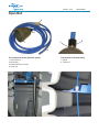
Issued: 3/12
Supersedes:
Open Bell
Installation and user manual
Description
The Flygt Open Bell system is primarily intended for use in
LPSS domestic sewer systems.
The measuring method is based on the compression of
atmospheric air that is captured in the system by the
hydrostatic pressure of a liquid column.
The Open Bell acts as a measuring probe, connected by
an air tube to a pressure sensor (Flygt LTU 301). This in
turn generates an analog signal that is processed by a
Flygt FGC or similar pump controller.
Laying of the tube
Connecting the tube to the bell
• In ground and other mechanically sensitive areas,
the pneumatic tube must additionally be laid in a
protective pipe.
Note: 90° corners are not allowed for the protective pipe!
When connecting the pneumatic tube to the bell piece,
proceed as follows:
1. Both ends of the pneumatic tube must be precisely
cut at right angels. If needed, make a fresh cut with
e.g. a sharp razor knife or tube cutter. Side cutting
pliers are not recommended!
2. Push the screw cap, which will be used for
supporting the weight of the hanging bell piece,
over the pneumatic tube.
3. A nipple is screwed into the top of the bell piece. Use
a wrench to tighten the fit in order to prevent the bell
piece from coming loose.
4. Detach the screw nut and slide it over the tube end.
5. Push the tube end firmly over the nipple and carefully tighten the screw nut by hand. Double check that the
tube is now securely fastened.
Observe the following precautions:
• Sharp bends and squeeze spots must be avoided.
• The pneumatic tube must be laid in a continuously rising pattern; Any loops are to be avoided. To this end, the tube may have to be shortened to suitable length.
• The tube must not be exposed to ultra violet rays (i.e. direct sunlight).
Maintenance
The Open Bell and pneumatic tube require regular
inspections with regard to pollution. To this end the
pneumatic tube has to be detached at the pressure
sensor/control panel end and compressed air be
blown in the direction of the bell piece. Thereafter
the bell piece should be cleaned inside and out.
Connecting the tube to the controller
Technical data
Please refer to the installation manual of the
corresponding pump controller.
Material, bell piece: cast iron, enamel painted
Material, pneumatic tube polyether polyurethane
Temperature range: 0 – 104 °F
Difference in temperature: +68 °F within 2h
Transmission length/Max tube length: 65 ft
Measurement range: 0 – 8 ft (0 – 0.25 bar)
Connection fitting/Nipple: ¼” x 10 mm pneumatic tube
Screw cap, dimension PG 11
Weight, complete: approximately 1.13 lbs.
Positioning in the pump sump
Observe the following pointers:
• The Open Bell is mounted hanging freely from the
end of the pneumatic tube.
• The screw cap is needed for supporting the weight of
the bell piece. The exact positioning in the pump
sump depends on both the type of control panel and
the layout of the pump sump.
• Please refer to the instructions in the Flygt Compit
C&M manual when applicable.
Denomination
Open Bell Tube length: 5 m (16.4 ft) Tube length: 10 m (32.8 ft) Tube length: 20 m (65.6 ft)
Part no.
834518
834519
834520
Issued: 3/12
Supersedes:
Open Bell
4
2
1
1
2
3
The components of the Open Bell system:
Components of the tube fitting:
1. cast bell piece
2. tube fitting
3. pneumatic tube (10 mm)
4. screw cap
1. nipple
2. screw nut