1
From Zero To
with
BLINKY
Em::Blocks and STM32L100 Series
Murat Ursavaş
www.muratursavas.com
To my first love and wife Ayşen and to my precious daughter Begüm…
Murat URSAVAŞ
Ankara, February/2014
This document can be redistributed, printed, duplicated and partially or completely copied,
with referring to the original document and author.
TABLE OF CONTENTS
About Me ............................................................................................................................................................................................ 4
Why Another Blinky Document?......................................................................................................................................................... 4
Why Em::Blocks? ................................................................................................................................................................................. 4
Why STM32? ....................................................................................................................................................................................... 4
Em::Blocks Installation ........................................................................................................................................................................ 4
Where Am I? What Is Thıs Place? ....................................................................................................................................................... 7
Creating the Project ............................................................................................................................................................................ 8
ST-Link Debug Probe Settings ....................................................................................................................................................... 13
Initial Project Files ............................................................................................................................................................................. 16
main.c............................................................................................................................................................................................ 16
startup_stm32l1xx_mdp.S ............................................................................................................................................................ 17
system_stm32l1xx.c and system_stm32l1xx.h ............................................................................................................................. 17
main.c Again .................................................................................................................................................................................. 17
stm32l1xx.h ................................................................................................................................................................................... 17
*.ld ................................................................................................................................................................................................ 18
Ready For Real Action? Let’s Code… ................................................................................................................................................. 18
STM32L1xx Standard Peripheral Library ........................................................................................................................................... 20
Peripheral Methods .......................................................................................................................................................................... 24
It’s Bug Extermination Time .............................................................................................................................................................. 28
A Simple Delay .............................................................................................................................................................................. 30
Interrupt Routines In ARM Cortex ................................................................................................................................................ 31
Clock Sources ................................................................................................................................................................................ 33
Optimization ..................................................................................................................................................................................... 33
Linking ............................................................................................................................................................................................... 36
Thanks ............................................................................................................................................................................................... 36
Up To Date Revision .......................................................................................................................................................................... 36
Appendix A: Creating “system_stm32l1xx.c” File From The Ground Up .......................................................................................... 37
Document History ............................................................................................................................................................................. 39
ABOUT ME
I was born in 1977 and graduated from Çukurova University Electrical and Electronics Engineering faculty in 2003. My carrier
started when I was five. My first job was doing cleaning in our streets patisserie. After some little jobs I became an office boy in a
computer store to learn something about PC’s. The calendars were showing year 1995. Before my graduation I worked as
computer technician, computer seller, web designer, software developer and 3D visual designer. In one period I was working for
a national game magazine as an editor.
After the graduation from the college, I did coach electrical systems design, embedded systems hardware and software design,
industrial design, desktop and network based software development. I’m still developing embedded systems (mostly software)
as of writing this document.
Note: As English is not my primary language, please excuse me for all the grammer mistakes.
WHY ANOTHER BLINKY DOCUMENT?
My personal experience has shown that the hardest part to learn a new micro controller architecture could be turning on an off
a simple LED, which is the embedded world’s “Hello World”, Blinky. The progress could be very difficult. Because you should get
familiar with new micro controller architecture, learn a new development toolchain and try to solve the problems you’ll face
with a little knowledge in your hands. After this steep learning curve, everything would become a bit easier and cleaner.
Because of that I’ll try to make this learning curve less steep and make you got the idea how to really develop embedded
software. It’s not something about writing a perfect simple code. This could be very easy. But this is about preparing you for the
future, which includes many bugs, sleepless nights and countless cups of coffee.
Also original Turkish name of the document is “Işıldak” therefore you’ll see the project name as that.
WHY EM::BLOCKS?
People who knows me closely, knows that I update the information about the tools I’m using at least twice a year. Before
discovering EmBlocks, my toolchain was a DIY collection, which consists from Eclipse, CDT, GNU-ARM, ARM-GCC, Zylin and Open
OCD. Before choosing this DIY toolchain I had done a comparison between some of the existing very well-known toolchains.
Interestingly the best result (as Flash / RAM usage wise) was taken from ARM-GCC compiler.
While continuing with that DIY toolchain, I encountered with EmBlocks, which was not come up with my researches before (in
fact Em::IDE was the first one but then I widened my search after realizing that there are some more tools). While considering
EmBlocks I had seen that the developer of EmBlocks (Gerard Zagema) was very proactive, very responsive to the users and was
constantly improving EmBlocks. Finally I had decided that EmBlocks was the best toolchain we could use.
Time has proven that I made the right decision and EmBlocks has been kept improving. My personal choice is still EmBlocks for
developing ARM based embedded software as of today.
WHY STM32?
It’s very easy to get the idea why ST is the leader of the ARM Cortex-M market. The STM32 family is really ideally positioned.
Moving vertical or horizontal in the family is very easy and convenient. There are lots of choices and at least one of them would
suit you. The last critical parameter, the price is also another plus for STM32. Therefore it had become our obvious choice in our
company.
The STM32L Value Line is a really interesting choice. Its quality is not comparable with its price. Hence we’ll be blinking our LED
with a Value Line discovery kit, which is STM32L100-DISCO. But you can do the same with other kits, too.
EM::BLOCKS INSTALLATION
We’ve built enough background for the document and can get to our actual work. Firstly we’ll download the toolchain from its
official website (http://www.emblocks.org/web/downloads-main).
You can download from any of the mirrors but don’t forget to validate the final file with a hashing method (such as SHA-1). You
might not see anything wrong within the installation but things can go bad later and you might not be able to spot the problem.
At the publish time of this document the version of the toolchain was 1.44. But it was 1.41 when I was started to write. So you may
see mixed versions in the screenshots but they are the same with 1.44. That’s why I didn’t bother to update them. The changed parts
are already updated regarding to the latest version.
Extract the “EmBlocks_x.yy.exe” file from the downloaded “EmBlocks_x.yy.zip” file to a temporary folder and execute it. If you
have the security settings activated, accept the warning. You’ll see the welcome window of the installation process.
Click “Next” button and accept the GPL license via clicking “I Agree” button. If you are wondering what the GPL v3 is visit
“gnu.org” or search the web about it.
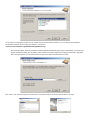
The next window will be about the feature selection of the toolchain. You won’t be paying anything for the features, so nothing
could keep you from selecting “Full” and continuing with the “Next” button.
The next step is selecting the installation path. Unlike some other well-known toolchains, you can select protected folders
comfortably. EmBlocks will be saving your settings in a folder like
“C:\Users\<YourUserName>\AppData\Roaming\EmBlocks\x.yy”.
Please note this folder, because if EmBlocks would be updated with breaking the settings compatibility, you would see a
default workspace without your old settings. They could be very easly transferred via copying and pasting in this folder.
Also a settings importer is on the TODO list but we don’t know when it would become a reality.
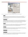
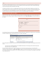
Click “Install” and make the copy process start. After a successful install you should see the window on the right.
WHERE AM I? WHAT IS THIS PLACE?
Keep calm and breath. Don’t worry, you are safe. If you still not have clicked on the EmBlocks icon, now is the best time…
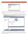
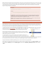
With the first start of EmBlocks you’ll see a window which shows you the supported compilers by EmBlocks and whether they
are found or not on your system. If you see a compiler as not found, even installed in your PC, you can easily include it to
EmBlocks, later.
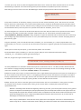
In fact this window tells also a story. As you see, EmBlocks supports many platforms including PIC. Even if the best supported platform is ARM as of
now, the project had been started for PIC’s. Plus, you can say “what’s doing ARMCC (Keil) here”. ARMCC could be a good compiler but saying the same
for the IDE (RealView) is not so easy for me. That’s why a quick web search could show you some forum threads in Keil’s web site about “why EmBlocks
is better than RealView IDE”.
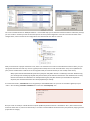
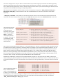
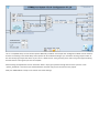
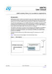
EmBlocks Editing Perspective User Interface
After the “startup hints” and “file association” windows you’ll see an interface like above. Basically this view (perspective)
consists of “workspace” window which tracks projects, symbols and files, ”editor” window which obviously will allow you edit
the source files and “Logs & others” window which shows the process outputs and logs. Of course the window types are more
than that but it’s enough for us to start.
It’s time to get our hands dirty and create our project “Işıldak”.
CREATING THE PROJECT
Click to “File / New / Project” menu item.
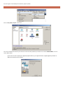
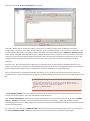
You’ll see a window which will let you choose the microcontroller platform you want to use. Select “STMicro-ARM” icon and
click to “Go” button.
If you want to create a project for a different platform than ST, you might encounter a slightly different path due to
differences between project wizards.
The next window will be the “Welcome” window of the wizard. Although it’s very polite, select “Skip this page next time” and
click “Next”. It doesn’t have to be so polite every time, right?
Enter the project name to the “Project Title” entry. Then select the folder, which will incude the project folder named after the
project, via clicking “…” button. Make sure EmBlocks have write rights for that folder. Therefore you should avoid using
protected folders like “Program Files” etc.
Of course choosing the root folder is also not the wisest choice but it sure makes writing such tutorial documents easier.
Also as a rule of thumb, you should choose names without spaces in it. Because these kind of IDE’s generally triggers another tools via command line
and generally the spaces within the names creates issues. Non-latin characters also could do the same, so avoiding them also would be a good choice.
You can check the final file path from the “Resulting filename”. Click “Next” to continue.
The next window will be the build configuration choice window. Click “Next” without changing anything at here.
It would be good to enter details to see the devil inside. Most probably you’ll get the “ARM-GCC EmBlocks Bare Metal” compiler as the only choice.
“Debug” and “Release” configurations will be always with you for all the development timeline. With the “Debug” configuration you would like to have
a configuration which makes development easier (finding the bugs faster, 1:1 source code – disassembly compatibility etc.). With the “Release”
configuration you would like to have faster or smaller code regarding to your goals. But you don’t have just these options. You can create infinite
configurations with your targets, like your alpha development target with lots of wires and pins etc.
Now choose the ARM Cortex core you’ll use. A very short datasheet or website reading will show you that the STM32L100RC has
an ARM Cortex M3 core. Therefore choose “Cortex M3” and click “Next”.
After the core choice you have to select the family of the MCU. The answer is in the name of MCU itself. After choosing
“STM32L1xx” from the list, click “Next”.
Select “STM32L100RC” from the last window about the microcontroller selection and click “Finish”.
You may ask here “why we haven’t chosen the microcontroller directly like the other toolchains and made it step by
step”. It’s easy to answer. Because ST’s ARM portfolio is very wide and a complete list would be very long and difficult to
choose the right one.
Mentioning the other choices would be very beneficial to understand what we are doing with our project.
“This is a library project”: This option will make your project a library for other projects. The resulting file cannot be executed in
an MCU directly. If you are developing a compiler or providing some proprietary software libraries for other companies, this
option could be good for you. But it’s not worth to use for your own projects since it will be better to keep your libraries as
sources in your project.
Make sure “This is a library project” option is not selected.
“Enable Semihosting:” Probably the name won’t ring any bells in your mind. But this feature is very useful for debug and is an
advantage of EmBlocks comparing with other free toolchains. Semihosting can be simply defined as “serial communication over
debug wire”. For example you are using STLink (like in this tutorial) as the debug probe and running your code in debug mode. If
you use semihosting, you can get a serial output from the output console of the EmBlocks without using any other hardware like
USART peripheral, USB serial converter etc. Simple printf, puts, putc functions will be enough.
For this project we won’t be using semihosting, therefore make sure this option is not selected.
“Standard Peripherals Library”: This option enables inclusion of the ST’s Standard Peripheral Library which has been created to
provide an interface for the MCU peripherals. You would likely enable this option in general but we’ll follow a different path for
this time. This is because I’d like to teach some of the important methods to find what you need.
Therefore make sure this option is not selected.
“Create hex file for …. target”: Originally the ARM Cortex development toolchains produce “elf” files which includes lots of
information like variables for debugging. And EmBlocks Bare Metal compiler is not an exception. But sometimes you could need
some intermediate files to use with other tools like a production downloader or software. The hex file (Intel Hex,
http://en.wikipedia.org/wiki/Intel_HEX) is the most common format for such usage. This option is generally used for “Release”
configurations. But if you like to also have for the Debug, enable also this option.
There is nothing wrong with this option but you can unselect any of it if you like.
“Set device settings at target level”: EmBlocks keeps the target configurations in a clever hierarchical structure. Such as;
Compiler toolchain configuration
o Project 1 configuration
Target 1 configuration (e.g. Debug)
Target 2 configuration (e.g. Release)
…
o Project 2 configuration
o Project 3 configuration
o …
This list can be widened up to your projects and configurations. Fundamentally it has three stages. Every sub-stage can just use
the upper stages options or append something or can dictate every option at target level. This option chooses the latter one for
the “Debug” and “Release” configurations. But the best option will be choosing this option unselected and then append some
options later if you want.
Therefore make sure “Set device settings at target level” option is not selected.
“Stack Size:” Maybe this one is the most confusing concept for a software development introduction document. We can
summarize the stack as the temporary note taking place where the MCU takes notes where it was before jumping to another
function. This way it could continue from where it left when it’s done with that function. The stack is designed as LIFO buffer
(Last In First Out) to able to work as it should. In some other platforms like PIC18, 16, the stack space has a fixed size and not
kept in RAM. But ARM processors keep the stack at the end of the RAM. It grows from end to beginning and does not have any
size limits other than your RAM size. But since your software will also use RAM they could overwrite the other one and cause
unexpected and erratic behavior. This option makes the linker check this condition for you. But don’t forget, this parameter will
not be your maximum stack usage. It’s just a predefined control value. Your stack usage could be higher or lower and you could
end up with strange acting devices in the field. So keep this always in your mind.
As our Blinky won’t be using this much stack space, you can leave “Stack Size” as it is.
“Heap Size”: Another parameter which is unnecessary for a simple Blinky. But knowing its meaning can be very beneficial.
“Heap” word has a very similar meaning like “Stack” but in programming world it has a different job. It means dynamically
created runtime variables. You see if you declare a variable in your program, the compiler would save space for it and all of the
properties would be known at the compilation. But sometimes you might want to have some variables which properties could
be unknown at development time. For such parameters we have a space called “Heap”. You can create variables or arrays with
different sizes and use it as you want. But as Spiderman’s uncle says, great power means great responsibility. Dynamic variables
could be very useful but they are also very dangerous. If you cannot manage them properly you can end up with very chaotic
running devices in the field with very hard to find bugs. As a general rule, don’t use dynamic variables unless you really have to.
So, keep the “Heap Size” as zero since you won’t be using any dynamic variables.
With clicking “Finish” you’ll finish this part of the wizard but you’re not done yet. Next stop will be the configuration of the
debug probe.
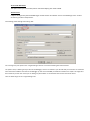
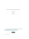
ST-LINK DEBUG PROBE SETTINGS
ST-Link Settings Window
You won’t be changing anything on this window but knowing what the options are crucial for the future.
Interface:
ARM Cortex microcontrollers have two debug interfaces, widely used common standard JTAG and ARM’s own
development for Cortex MCU’s, SWD (Serial Wire Debug). Details are very long, but long story short, SWD does mostly
what JTAG does with fewer signal lines (as low as 5 pins in practice) but some of the features, which probably you
wouldn’t need, are missing.
Vector Table Start:
This topic is a little bit advanced for this document but we can mention one of the ARM’s useful features, the address
space. ARM processors define all of the storage spaces in one linear address space. The flash, RAM, EEPROM, peripheral
registers, external SDRAM, all of them acts like they are on the same space. The flash memories address is 0x8000000
for the ST MCU’s, which is the “kick start” location of the processor. It is also the Vector Table Start.
Reset Type:
This option defines how EmBlocks (STLinkGDB) actually resets the target MCU. “System” and “Core” options send a reset
command over debug protocol but the “JTAG pin” option resets the MCU physically with pulling down the “nRST” pin.
This could be useful in some situations where the core could not accept debug commands.
Load Program:
If you would like to not download your software before starting to debug, you should enable this option. Most of the
time you would like to enable it because of your modified code. But sometimes you might want to connect to an already
running target without disturbing its running state or changing its flash state.
Enable Semihosting:
It’s about whether you’d like to enable or not the “Semihosting” which I explained earlier.
Execute from RAM:
If you make the linker place your code (.text) in the RAM, GDB gets the information about this section and knows the
place is R/W. But the device doesn’t know it as design and PC and SP registers must be set from the vector table for a
jump start. This option enables it and makes sure your software runs on RAM.
Vector Table Relocation:
This option moves your vector table (which I mentioned before) from Flash to RAM.
Verbose Level:
It defines the log level of the STLinkGDB. Bigger number means more details. And it’s overwhelmingly more. So don’t
increase it if you don’t really need to.
Finish debug probe settings with clicking “OK”.
You’ll change only one option in the “Target Settings” tab but I can share something about this window.
The options here, is defining how you will use the debugger, where it is located in your PC and how you connect to it. Unlike the
other toolchains EmBlocks connects to the debugger (in this case STLinkGDB) via network interface over TCP/IP. This might be a
bit unusual for you but also means you can debug any device which is connected to internet over the whole world.
Let’s see what we got in the “Target Settings” tab.
You’ll just enable “Run to main()” option here but I’d like to describe all of of the options for your information.
“Device description file” will not be necessary for Işıldak project but it would be very useful for your future projects. It’s
a standard definition file defined by ARM and includes the information about the MCU peripherals.They are provided by
manufacturers and EmBlocks has a repository for it. With this file you can track all of the peripherals’ states easily and
change them anytime you want.
“Don’t Reset after connect” would allow you to connect a running target without resetting it. But this option is only
useful if you had unselected the “Load program” option in the probe settings. With both of the options you can connect
a running target under the test anytime you want without disturbing its state.
“Run to main()” makes the debugger stop at the main function instead of the assembly startup code, which I’ll explain
later.
“Show all Registers” as the name suggests it gives a chance to see all registers of the MCU.
“Try to stop at valid source info” might not ring any bells at first, because you’ll think that all compilable code should
be valid. But what if the library, which is included in the project, has no related source? It could be precompiled (*.a) and
could not have any source information. If you try to step into a function from such library, EmBlocks cannot show any C
code to you because there isn’t any. This option makes EmBlocks not to stop inside a library function and stop by a
known valid source line instead. Think about a library call, like printf. Without this option you could end up stopped in
the disassembly code of the function and trying to investigate it. It could be scarier than wondering in a cemetary at
midnight.
Click “OK” to finish debugger settings part. The same settings will be copied to the “Release” configuration. You can alter it later
whenever you want.
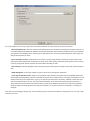
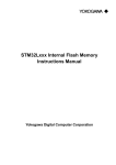
INITIAL PROJECT FILES
EmBlocks default project view
Now your project should have a view like shown above. This is a bit different than the actual folder structure of the project. This
is because EmBlocks’ default view settings categorizes the files according to their extensions. But I don’t like it and would like to
see as they are. To do that, right click on the project name in the workspace view and unselect the “Project Tree / Categorize
File Types” menu item.
With unselecting the option, you’ll end up a view like the right picture. It is the same view as your project folder.
If I was writing a common tutorial like the ones on the web, I should jump right in to the “main.c” file and start coding. But at
this stage you really should understand what you have in your hands. This is one of the most difficult things when starting ARM
development and getting what the files are really important.
We’ll have a different point of view and see the files like we are the compiler.
MAIN.C
Teaching C is not in the scope of this tutorial therefore if you are not familiar with this language, please take a break and read
something about that. But don’t worry basic knowledge is more than enough for the rest of the document.
A C compiler would start its job with the file which includes the “main()” function. The filename could be other than “main.c”,
it’s quite normal, but a file has to include a “main()” function, otherwise compiler cannot know where to start. In our case, as
expected, it’s the “main.c” file.
But a very hard to understand concept would pop up here. Microcontrollers has to do something before running “main()”
function. Sometimes compiler would hide them or some platforms would not need them completely. But ARM architecture is a
bit open and everything runs over the surface. So we have to make our ARM core startup properly.
STARTUP_STM32L1XX_MDP.S
Without any Assembly knowledge, this file could look like an ancient tomb text, but in fact it’s not so complicated. Basically a
processor knows where to run first code physically. In this case it’s our vector table start, 0x8000000 address. This address space
has to have something to run our software. And it’s the “startup_stm32l1xx_mdp.S” file. It has the reset vector, SystemInit and
interrupt handler function definitions. If processor jumps to here, these vectors show where to jump and run the necessary
actions, like reset or interrupt handling. Like we’ll see in this document, you’ll get the names of the interrupts from this file and
write your routines to process your interrupts.
As I mentioned, “SystemInit()” is also referenced in this startup file. It is a standard function across different brand ARM MCU’s .
It makes the core and peripheral clock adjustments before running “main()”. ST provides this functions implementation in
“system_stm32l1xx.c” file.
Warning: If you have some sort of obsessiveness, you might want to change this files extension to lowercase. But I
suggest you not to do that. GCC compiler does not like assembly files with lowercase extensions and does not take into
account while compiling. After the build, you would end up a build result with lots of errors related to linking.
SYSTEM_STM32L1XX.C AND SYSTEM_STM32L1XX.H
As I mentioned above, this file provides the “SystemInit()” function. It’s a part of the ST’s Standard Peripheral Library. This
function makes adjustments on the system core, bus and peripheral clocks. Without any changes you can run your
microcontroller with default settings. Later in your projects you might want to alter this file to meet your goals (Appendix A:
Creating “system_stm32l1xx.c” File From The Ground Up). But for this project it’s OK to go with defaults.
And the header file (*.h) is the global declaration file of the implementation. You can think this file like a table of contents file of
the *.c file to be able to use it externally.
MAIN.C AGAIN
OK, as we cleared the startup files, we can continue with “main.c” again. This file is your implementation base. You’ll call many
functions from “main()” function from the same file or other files and build your project with it. After hundreds and thousands
of calls you’ll get the functionality you want (hopefully). But don’t worry we don’t have to go that deep to blink our LED.
For using other files in your implementation, the caller file has to know what to call from the implementation file. In C language,
you do that via “#include”ing the header file of the implementation. This way you’ll say to compiler that you want to use the
files declared properties and methods.
Although you cannot see right now, we’ll use the peripheral library which is created by ST MCD (Micro Controller Division).
EmBlocks started to provide this library after 1.44 version but we didn’t include them for a purpose I mentioned before. Even we
didn’t select the library EmBlocks does provide some of the peripheral library files which is enough to start. Let’s see what they
are.
STM32L1XX.H
It is probably the most important file of the peripheral library. Almost all of the MCU’s peripherals addresses and registers are
defined in this file. We can call it as a gateway to STM32L1xx MCU’s. That’s why you’ll see an “#include stm32l1xx.h” statement
in every file which utilizes MCU’s peripherals.
*.LD
Don’t expect to understand these files at first. They are simple and short but not so easy to get what they are doing when you
look inside. Generally the defaults will work for you but sometimes you have to edit to fit your needs. And at that time things
can go very wrong if you don’t know what you are doing.
This file has instructions to “link” your compiled object code into a final and runnable image on the MCU. If you “Build” your
project compiler toolchain starts to convert your source code into object code one file at a time. At that stage the object codes
are separated and has to be linked together to make your project work together. The compiler toolchain has a linker which
makes this linking with the instructions taken from the “*.ld” files. That’s why these files are so important.
READY FOR REAL ACTION? LET’S CODE…
Double click on the “main.c” from the workspace window and open it in the editor window. As you can see it is fairly simple. To
make sure you had created the project correctly you should build it now. Click “Build / Build Target” menu item and check out
the output.
/*
**
**
Main.c
**
**
**********************************************************************/
/*
Last committed:
$Revision: 00 $
Last changed by:
$Author: $
Last changed date: $Date: $
ID:
$Id: $
**********************************************************************/
int main(void)
{
while(1)
{
}
}
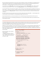
If everything goes right you should see something like the picture below in the “Logs & others” window. If you’re not seeing the
window you might be closed it unintentionally. Press “F2” to make it visible again.
If you’re seeing the final image size information that means the build operation was successful and everything you had done was
correct.
If you click on the “bin\Debug\Isildak.map” line EmBlocks would jump in to the map file, which includes many useful
information about your compiled image.
Don’t panic with the “Warning” word. There is no place on fire or you didn’t do anything wrong. It’s just a default build
configuration keyword definition (“__DONT_INIT_VTABLE”) triggers an intentionally placed warning in the “system_stm32l1xx.c”
file, to make sure developer knows what he or she is doing. If you double click on the warning you’ll see EmBlocks will jump right
to the related code lines.
#ifndef __DONT_INIT_VTABLE
#ifdef VECT_TAB_SRAM
SCB->VTOR = SRAM_BASE | VECT_TAB_OFFSET; /* Vector Table Relocation in Internal SRAM */
#else
SCB->VTOR = FLASH_BASE | VECT_TAB_OFFSET; /* Vector Table Relocation in Internal FLASH */
#endif
#else
#warning For release version do not use __DONT_INIT_VTABLE (see above).
#endif
You can see that the line with marked with red has been placed to warn the developer. OK, you have been warned and still don’t
like to see a warning after a build. So you got the idea why this is important (trying to move vector table to the RAM while
debugging is not a good idea) and can get rid of the warning.
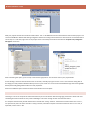
To do that, open project build options via clicking “Project / Build Options” menu item (if you have more projects in your
workspace, make sure you had selected Isildak to open the right settings). You’ll see a window like the one below.
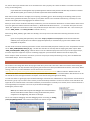
Click on the “Debug” configuration, first (1). Then select “Compiler Settings” tab (2). Select “#defines” tab (3). Delete the line
which is marked in the picture (“__DONT_INIT_VTABLE”). If you look into the “system_stm32l1xx.c” file you’ll see that you
cannot use “VECT_TAB_SRAM” keyword in any place of the project (especially here). It could mess up the debugging with STLink.
After mastering the toolchain and gaining enough experience, you can use this keyword - only in your Release configuration -.
While we are here, I can give you some little hints about this place. This “#define” area is used to define some keywords and
values for all over the project. The words which have been written here will be defined for all files. You’ll see what this means
later.
Press “OK” and you’ll see a message box like the one on the right. It’s
obvious what it’s asking, select “Don’t annoy me again” not to see this
message box everytime you build. And click “Yes” to confirm.
You’ll see the project will be build without any warnings. Cool…
Before starting actual coding I’d like to explain what the “main()” does. I know, right now many of you says “come on, this is just
too much”. For you, yes this is really very simple, but for couple people who never have done a project before, it’s really hard to
continue without this information. Because of that, who have experience; please continue to the next topic. And the most
beginner level grasshoppers, come with me.
int main(void)
{
/* This is the one time settings area. You’ll do your adjustments like
* defining your inputs, outputs etc.
*/
while(1)
{
/* This is the endless loop. Your device will run in here to the eternity (what a device, ha?)
* You’ll write the repeating jobs, checks etc in here. */
}
}
/* int main(void): This line defines our famous main function and says this function does not need any
* variables to run and return an integer (for his platform it’s a signed 32bit number). Actually you
* wouldn’t want to return anything because an embedded device never quits from main, but to make GCC
* stop whining about the return value, we’re using an int at here.
*
* while(1): This loop is your main loop. It should run to the eternity (in theory of course) and do your
* repetitive jobs. For example in this case it will turn on and off our LED.
*/
STM32L1XX STANDARD PERIPHERAL LIBRARY
Since everything is in place, we’re ready to go. Next job is downloading the Standard Peripheral Library which is provided by ST
without any cost. The primary role of this library is hiding many o the numeric hard to remember details and helping to control
the peripherals with much nicer readable and rememberable functions and variables.
To download this library, go to the web page of the STM32L100RC and navigate to the “Design Resources” section. You’ll see a
download link with the “STSW-STM32077” code somewhere below in the page. (You
can click to the code at here. In any errors search the web quickly with this code.)
After finishing the download, extract the contents of the file to an easiliy accessible
temporary folder. You’ll be accessing frequently here. After extraction you should see a
folder structure like the one on the right.
The marked folder is the only necessary folder (with its subfolder and files) for our
project (it will also be included if you select the library option in project creation as SPL
name). The other folders include many other files to help us, and you’ll see how they do that later. Also you can find a help file in
the root folder of the library. Not like a real help, just a compiled doxygen output, but a good point for a reference.
Copy the marked folder “STM32L1xx_StdPeriph_Driver” and its contents into our project folder.
After copying, you should add the necessary files to our project to make it compiled in builds. Click “Project / Add Files” menu
item and select “stm32l1xx_rcc.c” and “stm32l1xx_gpio.c” files from the “STM32L1xx_StdPeriph_Driver\src“ folder and click
“Open”.
You’ll see a window labeled as “Multiple Selection”. This window helps you to select file and build relations individually. And yes,
you can include or exclude your files for the build process for every build configuration. Since we’ll use them for both of the
configurations, make sure both of the configurations are selected and click “OK” to continue.
Now you should have a project view like the one, above. The new files have a lock icon beneath them but don’t worry, it’s just
saying that these files are read only. And it’s a good practice to keep them so and never edit them. They can be updated and
your previous modifications could be lost in the magnetic fields (or electrical fields if you use an SSD) of the history.
Many of the tutorials would add all of the source files from this folder. But this is something I don’t like. With this way,
you cannot get the meanings of the files and you’ll do what you do without consciousness. The methods we’ll use may
become much harder to understand. For example choosing only two files could let you remember two important
keywords, RCC and GPIO which are the critical peripherals for a Blinky.
As I mentioned earlier, “stm32l1xx.h” file is the gateway to the STM32L1 MCU. So you have to include this gateway to your
“main.c” file via adding “#include “stm32l1xx.h” line over the “int main(void)” line.
#include "stm32l1x.h"
int main(void)
{
while(1)
{
}
}
But you’re still not ready for a build. Because compiler (EmBlocks) knows where the “stm32l1xx.h” file is, but it doesn’t know
where the other files are, which are referred by it. You have to make EmBlocks know where they are (obviously copying into the
project wasn’t enough).
To do that, click to the “Project / Build Options” menu item.
First select “Isildak” project name from the left (1). This way you’re making a change which can affect all of the build
configurations, not just one. Then select “Search Directories” (2) and “Includes” (3) tabs. As you can see only one folder, “.\Inc”,
has been added to the project. Click “Add” to add our new folder. Select “inc” folder from the “STM32L1xx_StdPeriph_Driver”
folder. After choosing the folder EmBlocks will ask us, whether we want to keep it relative or not. Since the universe is build on
relativity it’s a good choice to keep our folder entry relative. Also while moving your project into another place you won’t get
struggled with the absolute paths. Now you should see an entry like (5). Click “OK” and close the build options window.
Now build…
Bummer! Errors, again? And lots of them, right? (This could be a good time to check out what “Undefined reference” error
means). You’ve done your homework and saw that the declarations of the functions are missing and compiler cannot find them.
But you had shown the header files place to EmBlocks? Isn’t adding “stm32l1xx.h” as a gateway enough?
Let’s see a quick search in the gateway header file could help us or not. The file is long but early parts (from line 69 to 87)
include some clues. It says something about the type choice about the MCU. Following that, we see the lines below after the line
89:
#if !defined USE_STDPERIPH_DRIVER
/**
* @brief Comment the line below if you will not use the peripherals drivers.
In this case, these drivers will not be included and the application code will
be based on direct access to peripherals registers
*/
/*#define USE_STDPERIPH_DRIVER*/
#endif
“USE_STDPERIPH_DRIVER”. Yes, this is what we are trying to do. So, looks like we have to implicitly tell to the toolchain we
want to use this library (driver). Let’s make this definition known by all files.
Open “Project / Build Options” from the menu and like we did before click on the Isildak on the left side. And click “Compiler
Settings”, “#defines” respectively. (You had something similar before, while deleting “__DONT_INIT_VTABLE” keyword,
remember? But it was only one build configuration. This time you will add a keyword definition and alternatively it will be for all
of our build configurations.)
For a new line hit enter after the “STM32L1XX_MDP” statement and write down the keyword we just saw in the “stm32l1xx.h”
file: “USE_STDPERIPH_DRIVER” (without the quotes). Click OK to close the window. And build the project again.
I can hear you all say “Come on, what kind of guidance document is this?”. Please calm down and bear with me. It’s not really
about blinking a simple LED. It’s all about learning how to pass the obstacles and problems you’ll face in the future.
With clicking on the error wou’ll see in the “Build Messages” window and jump to the line which causes the trouble.
#ifdef USE_STDPERIPH_DRIVER
#include "stm32l1xx_conf.h"
#endif
It says that to be able to use the library properly, we have to use a file named “stm32l1xx_conf.h”. We haven’t seen a file like
that. Do we have to create and fill it or try to find it from elsewhere? Let’s act wisely. Somehow we have found the files, which
include “stm32l1xx” word in its name, from the library. Finding also this one wouldn’t be a surprise. Go to your folder which you
had extracted the library in the first place. Do a quick file search with the “stm32l1xx_conf.h” name.
You found the gold mine. There are lots of documents with the same name. OK, then which one? A quick look in the list shows
that all of the found files are listed under “Examples” folder except only one. The end of the list shows a folder named
“Project\STM32L1xx_StdPeriph_Templates”. Bingo, templates. Go right into that folder and see that the files we’re mentioning
from the beginning of this document are all here. An “A-ha, that’s where they are all came from” moment. Everything starts to
get less blurry, right?
Copy the “stm32l1xx_conf.h” file and two other files (“stm32l1xx_it.h” and “stm32l1xx_it.c”) into the project folder to the
proper folders (“Inc” and “Src”). If you are still not sure where to copy them, it might be a good idea to start this document over
again.
I know you are curious why we copied “_it” files. Please be patient. You’ll see later…
We should add the copied “stm32l1xx_it.c” file to our project. Apply the same method like we did while adding
“stm32l1xx_rcc.c”. And build the project again with pressing F7.
How nice, we got errors again. And this time it says:
Src\stm32l1xx_it.c|32|fatal error: main.h: No such file or directory|
||=== Build finished: 1 errors, 0 warnings (0 minutes, 0 seconds) ===|
The newly added file has an “#include” directive which points to a file named “main.h”. You didn’t provide a file like that and
don’t intend to. Copying everything could lengthten our learning process therefore we have to start editing something. Double
click on the “stm32l1xx_it.c” and find the “#include “main.h”” line and delete it.
Rebuild and couple of errors again. I think we kinda start to like it, right? Double clicking the first error opens the “stm32l1xx_it.c”
file. Error indicator shows the line 143. There is a “TimingDelay_Decrement” function call reference but compiler is not able to
find any implementation of it. That’s right, we don’t have such function right now and therefore we should delete this function
call. Delete this line without touching the “Systick_Handler” function definition and its brackets.
Rebuild… My God, only one error has been gone, the rest still lies there. All errors are related to an “assert_param” function.
The compiler tries to say that it cannot find the “assert_param” function which is called by the ST peripheral library
implementation files.
Well this is something which shouldn’t be happening. Because if you check, you’ll see all of the necessary “assert_param”
functions are defined in the header files of the peripheral library and we already had included it in the project and it has
to be found by the compiler. But somehow it doesn’t work at compilation time and I had to include same directory to all
of the build configurations. This is a bug and it probably will be solved soon. But as of version 1.42, it’s there and we
should apply our workaround written below.
Select “Project / Build Options” menu and click on the project name in the left pane. Then click to “Search Directories”
tab and “Copy All To…” button on the bottom. Select “Debug” from the shown window and continue with clicking “OK”
button. While still “Build Options” window is open if you click on the “Debug” you’ll see that the same entries have been
copied to here. Click “OK” to close window.
Press “F7” shortcut to build the project again and finally, a result without warnings and errors. Great…
The project at this moment is like a template for your future STM32L1xx projects. If you put the project somewhere else at this
stage you can later copy it back to create a new project via changing the project name. You can even create a template within
EmBlocks and create it everytime you want. I suggest you to try it after finishing this document.
PERIPHERAL METHODS
We’re very close to blink our LED. But we’re not certain what to do next, isn’t it? Well, then this is a good time to return to the
basics.
How can a micro controller switch power to a component? Of course via one of its outputs. And how we name the outputs?
General purpose input output, GPIO. This is something familiar; you had included such file to your project. But you need a
method which is better than directly messing up with this file. So far, ST Library has been very helpful. Would they make a favor
again this time?
We’re going to the first ST library folder with a hope about finding and “example”. And this is your lucky day; there is a
“STM32L1xx_StdPeriph_Examples” folder under the “Project” folder. We’re opening it and Bingo! Didn’t you felt like you had
found Alibaba’s cave with auto login enabled? We can see all of the names of the peripherals and under them there are a lot of
different subjects related to that peripheral. You should keep this place somewhere in your mind, because you’ll be visiting this
folder frequently.
Since our goal is to switch a GPIO, you should open the “GPIO” folder. There is a folder named “IOToggle”. Yes, this is what we
want, toggling. Opening the folder reveals that there is more than information, it’s a ready project for the job. But don’t get
excited this early. First, copying everything (without making any changes) would make your learning process worse and long.
Second, these examples are for rich people, who can pay for the Eval Kits. Not for us with our poorman’s discovery kits. No, this
is not our destiny right? Then it’s time to punch this file right in the, I don’t know, main? (I’m using Notepad++ for these kinds of
things but you can use EmBlocks, too, if you promise not to mix things up.
As a general knowledge I can say, that the useful files would be generally “main.c” and “stm32l1xx_it.c” files. If you look closely
you’ll see that they are fairly standard files which are also included in our project.
Now start to inspect the example “main.c” file from the beginning.
You can see some comment lines related to the file. Sometimes these comment lines could be very important since critical
subjects could be mentioned up there, but this time they are just “welcome” lines. Then after that you’d see the “Includes”
section.
/* Includes ------------------------------------------------------------------*/
#include "stm32l1xx.h"
#ifdef USE_STM32L152D_EVAL
#include "stm32l152d_eval.h"
#define GPIO_PIN_X GPIO_Pin_3
#define GPIO_PIN_Y GPIO_Pin_7
#define BSRR_VAL 0x88
#elif defined USE_STM32L152_EVAL
#include "stm32l152_eval.h"
#define GPIO_PIN_X GPIO_Pin_0
#define GPIO_PIN_Y GPIO_Pin_1
#define BSRR_VAL 0x03
#endif
You can see the “Eval Kit” thing at here. But first you’ll not be surprised with seeing “stm32l1xx.h”. Continue with the joy of
knowing what this line is.
Then find the “main()” function in which the job will start. You’ll see the following line right after the comment lines about what
the “SystemInit” function does.
/* GPIOD Periph clock enable */
RCC_AHBPeriphClockCmd(RCC_AHBPeriph_GPIOD, ENABLE);
This is where every rookie falls (remember the Matrix). You should always enable the peripherals clock first before trying to
work with it. If you had worked with PIC or other MCU’s you would know that this is not necessary with them. For example after
making it an output via setting its tris bits you just push it up or pull it down. But that’s not the case with ARM. Before to be able
to hear what you say, the peripheral should be up and running. And for that it has to have a clock signal. That’s what the
function above does. We have to add this function call into our code right after the start of “main()”. To be able to catch the
errors early it’s a good practice to build it in every step. The only penalty would be the build time but I have to admit, EmBlocks
is fast, “speedy Gonzales” fast.
Let’s see the function call details. As I mentioned earlier, the uppercase prefixes say where the function belongs. This function
belongs to RCC peripheral (Reset and Clock Control). AHB “AMBA High-performance Bus” refers to the main bus of micro
controller and many of the peripherals are connected to core with it. Hence “RCC_AHBPeriphClockCmd” means “I want to
change the state of the clock supply for this peripheral”. The parameters are the peripheral and it’s the new clock supply state.
“RCC_AHBPeriph_GPIOD” is the GPIO peripheral which is connected to the “PD” pins of the MCU. You may have thought that
this is not a peripheral but indeed it is. Everythings in the MCU except the core and memory is a peripheral. Just not every MCU
shares the details with you.
With this fnction call you have understood that it has been put to enable the clock supply of GPIOD. But you have to remember
one thing. The LED we want to blink is not connected to GPIOD. You don’t even have to look for the datasheet or schematics.
Just looking to the LED on the left of the kit is enough (you can see it also in the documents cover). It says PC9. Port C pin 9.
Good, you just have to change the D to the C. The new function call becomes this;
/* GPIOC Periph clock enable */
RCC_AHBPeriphClockCmd(RCC_AHBPeriph_GPIOC, ENABLE);
While you were trying to change the code you were prompted to choose from some options, isn’t it? This is the code completion
helper of the EmBlocks. This is something still missing from the expensive IDE’s even today. Eclipse based IDE users are also
familiar with this feature. It is very helpful because you can use long and easily understandable variable names without any
additional effort and this could lead to fewer bugs in the future.
Now, back to the example code…
/* Configure PD0 and PD1 or PD3 and PD7 in output pushpull mode */
GPIO_InitStructure.GPIO_Pin = GPIO_PIN_X | GPIO_PIN_Y;
GPIO_InitStructure.GPIO_Mode = GPIO_Mode_OUT;
GPIO_InitStructure.GPIO_OType = GPIO_OType_PP;
GPIO_InitStructure.GPIO_Speed = GPIO_Speed_40MHz;
GPIO_InitStructure.GPIO_PuPd = GPIO_PuPd_NOPULL;
GPIO_Init(GPIOD, &GPIO_InitStructure);
We were just planning to blink a LED but this looks like something more. Let’s try to simplfy it.
There is a struct instance named as “GPIO_InitStructure” but it doesn’t look like declared hereabout. Searching it shows us that
it has been declared as global variable in the upper parts of the file.
“Init”, is the short form of the initialization. And
“GPIO_Init” should be something about the
startup setting of a GPIO.
GPIO_InitTypeDef
GPIO_InitStructure;
You’ll see a lot of “xxxxxx_InitTypeDef”s in the future while working with the peripheral library. They are used to make
some initial adjustments for the related “xxxxxx” peripheral.
But as a general rule of thumb, don’t make any of your variables global, if it’s not necessary. If you want the variables value
preserved, just make it local and static. This way you can avoid some erroneous accesses to the variable and have a simpler,
cleaner code structure. Since we’ll setup our LED pins status only one time, we don’t need to make the struct instance global.
Copy the variable declaration right under the newly put clock function call. And then copy the 4 pin configuration code after that.
You have to change it to the one port. Here’s an advice. Make sure you have changed your comments first. Because generally,
after technically finishing your work, the last thing would be dealing with your comments. You will end up with taking a cup of
tea or coffee and enjoying the victory moment. And the change you had to make in your comment will be gone forever, which is
very precious in the projects that are big or infrequently updated.
OK, you got me and changed the comment. Now you have to change the pin assignment. “GPIO_InitStructure.GPIO_Pin =
GPIO_PIN_X | GPIO_PIN_Y;” statement does not look like a standard definition in the library. Let’s build it to see what’s
happening.
“’GPIO_PIN_X’ undeclared” error justifies us. Then what can we write here? To learn that we have to find out what kind of
information the struct member carries. Right click on the “GPIO_Pin” word and click on the “Find declaration of:” menu item.
This action will jump you
right to the declaration
of the right clicked
parameter, which is also
can be done by “CTRL +
SHIFT + .” keyboard
shortcut (pay attention
to the dot). You’ll end up
in the definition of the
GPIO_InitTypeDef struct
like shown here.
typedef struct
{
uint32_t GPIO_Pin;
/*!< Specifies the GPIO pins to be configured.
This parameter can be any value of @ref GPIO_pins_define */
GPIOMode_TypeDef GPIO_Mode;
/*!< Specifies the operating mode for the selected pins.
This parameter can be a value of @ref GPIOMode_TypeDef */
GPIOSpeed_TypeDef GPIO_Speed;
/*!< Specifies the speed for the selected pins.
This parameter can be a value of @ref GPIOSpeed_TypeDef */
GPIOOType_TypeDef GPIO_OType;
/*!< Specifies the operating output type for the selected pins.
This parameter can be a value of @ref GPIOOType_TypeDef */
GPIOPuPd_TypeDef GPIO_PuPd;
/*!< Specifies the operating Pull-up/Pull down for the selected pins.
This parameter can be a value of @ref GPIOPuPd_TypeDef */
}GPIO_InitTypeDef;
OK, we have to understand what the “GPIO_Pin” is. The variable type is an “uint32_t”. This doesn’t look like a standard C type. A
quick web search will show you that this is something about the portability of your code between different platforms. You may
think as “why we need something like that”? It’s simple, not all of the MCU’s and compilers are created equal, like we human
beings. Some of are 8 bit, some 16 bits. Many compilers will define an “int” as signed 16 bit integer unlike ARM-GCC which
defines it as 32 bit signed integer. With these additional type definitions you can easily make your code portable via changing
them. So, trying to jump to this definition can not help us since it’s a simple 32 bit unsigned integer. It would be better if it was
an enum or struct. This way we could re-jump into that definition and see what it does.
Hopefully the ST MCD team consists from very thoughtful fellows; they left us a note right next to the GPIO_Pin declaration.
They say “GPIO_pins_define” keyword is the key for the heaven and we have to follow it. Press “CTRL + F” shortcut to find where
this keyword used (we cannot use “find declaration” trick because this is not a type declaration). This search takes us to the lines
below.
/** @defgroup GPIO_pins_define
* @{
*/
#define GPIO_Pin_0
#define GPIO_Pin_1
#define GPIO_Pin_2
#define GPIO_Pin_3
#define GPIO_Pin_4
#define GPIO_Pin_5
...
#define GPIO_Pin_All
((uint16_t)0x0001)
((uint16_t)0x0002)
((uint16_t)0x0004)
((uint16_t)0x0008)
((uint16_t)0x0010)
((uint16_t)0x0020)
/*!<
/*!<
/*!<
/*!<
/*!<
/*!<
Pin
Pin
Pin
Pin
Pin
Pin
0
1
2
3
4
5
selected
selected
selected
selected
selected
selected
*/
*/
*/
*/
*/
*/
There are definitions based on
the pin number and their
((uint16_t)0xFFFF) /*!< All pins selected */
values are standing right next
to them. So, our value should
be “GPIO_Pin_9”, since it’s the most logical sounding one. With “whoever did this should be done right” thought we can
continue mind at piece. Switch to the opened “main.c” file in the editor area and overwrite the “X and Y” line with the
“GPIO_InitStructure.GPIO_Pin = GPIO_Pin_9;” statement.
The next statement, “GPIO_InitStructure.GPIO_Mode = GPIO_Mode_OUT;”, says that this pin will be used as an output. That’s
right. We want to supply power to a LED. Leave this line as it is.
“GPIO_InitStructure.GPIO_OType = GPIO_OType_PP;” statement gives us a clue about a practicality of ARM MCU’s. Many of
the PIC16 and PIC18 users would not know different types of outputs, because they only have push-pull configuration. But in
here we also have “Open Drain” configuration chance at here. This way you can easily do something without using additional
BJT’s or FET’s. But in this case you’ll change the output from VSS to VDD, therefore leave also this line as it is.
“GPIO_InitStructure.GPIO_Speed = GPIO_Speed_40MHz;” statement tells us something about the switching speed of the GPIO.
This is really high for a simple blinking LED. To reduce the power consumption, we should make it slower. Delete the “40MHz”
part of the last parameter and you’ll be prompted with the available options like shown below. If it would not be shown you can
press “CTRL + SPACE” to see that.
The library gives us 4 choices. Since our Blinky would have a very long period (about 500 ms) you can select the lowest possible
speed, “GPIO_Speed_400KHz”.
“GPIO_InitStructure.GPIO_PuPd = GPIO_PuPd_NOPULL;” line is basically not relevant with an output. It’s about the pull-up or
pull-down configuration of an input. We can leave this line as it is.
As a good practice, never leave a struct member alone. Set to a certain value implicitly, like zero. Because other way,
library may not mask the member properly and this could lead strange and unpredictable behaviour.
And lastly if you still haven’t done yet, change the “GPIOD” parameter to “GPIOC” in the “GPIO_Init(GPIOD,
&GPIO_InitStructure)” statement. Build at this point and if you have errors, check what we have done till here, again.
Later on, check out what the library functions actually do. Look for the user manual (released as RMxxxx) of the MCU
and check the relation with the code. This will lead to a deeper understanding of the related mcu family. This is
important because sometimes you could not find something in the library and would follow the path in reverse, from the
user manual to the library.
Right now we have a
main function like this:
int main(void)
{
/* GPIOC Periph clock enable */
RCC_AHBPeriphClockCmd(RCC_AHBPeriph_GPIOC, ENABLE);
GPIO_InitTypeDef
GPIO_InitStructure;
/* Configure PC9 in output pushpull mode */
GPIO_InitStructure.GPIO_Pin = GPIO_Pin_9;
GPIO_InitStructure.GPIO_Mode = GPIO_Mode_OUT;
GPIO_InitStructure.GPIO_OType = GPIO_OType_PP;
GPIO_InitStructure.GPIO_Speed = GPIO_Speed_400KHz;
GPIO_InitStructure.GPIO_PuPd = GPIO_PuPd_NOPULL;
GPIO_Init(GPIOC, &GPIO_InitStructure);
while(1)
{
}
}
As the initialization is completed, you can continue with the continuous job that the device will do in its life time. Our very
complicated device should switch power to a LED periodically, therefore you should write something which pushes the output
pin to VDD and pulls it back to the VSS after some time.
Let’s go back to the library example code. There are some operations but they don’t look like what we expect. There should be
some functions starting with GPIO prefix. Instead we see some statements with arrow signs. (If you still haven’t got what they
are, then it means you wouldn’t listen to me and didn’t learn the C properly. Let’s check out what it is and return back. Don’t
worry, I’ll be waiting here).
In fact these lines are the efficient way of switching GPIO’s without some function calls. But they are hard to read and
find. Because of that, for us starters, it’s better to find some human readable methods.
With “what can we do about it” thoughts, we’re opening “stm32l1xx_gpio.h” file and looking for something usable. (In fact
because of the good documentation, the help file (*.chm) which stands in the root folder of the library, could help us in this
situation. But anyway we’ll keep digging the file itself this time).
When you check out the contents of the library header files, you’ll see the function declarations are at the bottom of the files as
usual. Go right to the bottom of the file and find the “/* GPIO Read and Write Functions … */” comment. And you’ll see some
“Reset, Set” keywords in the function names. They could be what you need. “Bit” is very similar with “Pin”. Then it means you
can use “GPIO_SetBits” and “GPIO_ResetBits” methods. Let’s try.
Start writing “GPIO_SetBits(“ right under the “while(1)” line and you’ll see a hint about the necessary parameters for the
function.
If you are not getting this information, click to the “Project / Reparse current project” menu.This will restart the
EmBlocks parser and fix the issue. And don’t forget this operation; it will solve many of your issues related to code
complation in the future.
The hint shows us that the necessary parameters are the name of the GPIO peripheral and the pin name. Complete the function
call as “GPIO_SetBits(GPIOC, GPIO_Pin_9);”. This will drive the LED. The next step will be stopping the power output. Write
“GPIO_ResetBits(GPIOC, GPIO_Pin_9);” after the drive line to do it. Build the project to make sure you’ve done right and yes,
one more step to the happiness. If you are not feeling happy then you should check what we have done step by step.
We’re ready to rumble. It’s time for real action. (I can hear many of you smart pants thinking as “hey, we’re not defined the
intermediate delays”. Just be a bit patient.)
IT’S BUG EXTERMINATION TIME
You’ve done a lot of things but didn’t do anyting to show off to your friends. Let’s blink a LED to show them what kind of geek
you are (maybe the next step would be hacking some government servers with prerendered 3D animations, who knows). Before
starting, make sure you had installed the correct driver which can be found
“http://www.st.com/web/catalog/tools/FM146/CL1984/SC724/SS1677/PF251168” address under the “Related Tools and
Software” title. After a correct installation connect your STM32L100C-DISCO kit with a standard USB A to Mini B cable to the PC.
You should see some messages related to “STLink/V2” name. And it’s the green light for the debug.
To make sure there is a green light, open the Device Manager and look for the “STM32 STLink” entry under the “Universal Serial
Bus devices” group. If you can see it then it means you had successfully installed it. You also can check it via the red LED on the
upper left corner of the kit. With a successful installation you should have it contantly on. If it blinks, then it means the STLink is
not recognized by the computer. In this case try to reinstall the debugger via
following the previous steps.
Note: My OS is Win8 and recognizes the debugger like I mentioned above.
But the virtual Win7 machine which I’m using for the document process
recognized it a bit differently, like shown on the right.
You’re now ready for debugging. Start the debugging session via clicking to “Debug
/ Start/stop Debug Session” menu item or the toolbar icon shown on right.
If everything is alright, you should see a command prompt like below.
STLinkGDB, developed by Gerard Zagema
This window should wait in this stage and at the same time EmBlocks should switch to the “Debug” perspective. At this moment
you may see a message box asking that you want this perspective to be saved or not. As usual select “Don’t annoy me again”
and click to “Yes”.
You should see a
workspace like shown
on right.
If you see the source codes of the “startup_stm32l1xx_mdp.S” file at the start of the debug session, then it means you
forgot to select “Run to main()” options from the target options. You can select this option like I told you before.
The yellow arrow at the first line shows where the processor core is waiting. This means the startup code has been successfully
executed and the debugger stopped the core at the start of our main function.
Now you can enjoy running the target. Click “Debug / Run” fom the menu or the
toolbar icon shown on right.
And the long waited victory moment. Our LED named LD3 is shining like sun, right? Now you have significant knowledge about a
new development toolchain.
But as the endorphine level decreases you may start to realize something. The LED is not that bright, isn’t it? Besides that, we
supposed to blink a LED but this is just a half bright dull light bulb. If you have a scope you can trace the PC9 signal and see
what’s going on. The LED is blinking but it’so fast your eyes cannot catch it. It’s just seen half bright.
Let’s stop the core via “Debug / Stop” menu and revert its state back to start with “Debug / Reset” menu. After the yellow
arrow reverts back to the “RCC… bla bla” line use the “Debug / Next Line” menu. (You should get used to F10 shortcut.)
You’ve seen the yellow arrow passed to the “Next Line”. But in fact the core not passed anything. It executed the previous line,
which is “RCC_...” function call. It have run whatever the function includes. If you would like to see what’s going on under that
call, you should click to “Debug / Step Into” menu (F11). This way you could trace the function call down to the bottom level
instructions.
Press F10 to do the same until the yellow arrow arrives to the line which starts with “GPIO_SetBits…”. And do the golden shot
which will light our LED via hitting F10. A calming bright green light, tastes like success.
Keep hitting F10 without hurry and trace the yellow arrow. It could be blinking manually but we have done our job or so.
But this shouldn’t stop who is into developing something new, isn’t it? Our LED should blink without any intervention from us,
like one blink per second.
A SIMPLE DELAY
The simplest delaying function would be a pointless loop for spending some time. But it won’t teach you some of the necessary
features of the ARM MCU and there would be many incertanities. This means we need something definite based on time.
Almost all of the MCU’s have at least one timer peripheral for such purpose.
ARM also has a timer integrated in the core named as SysTick. Its primary purpose is serving time base for RTOS schedulers, but
this is a bit advanced topic and out of our scope. The secondary purpose of SysTick is serving basic timing needs, which fits us
better. We can dig into user manual but maybe checking the examples again could be a good idea. The MCD team could leave us
a favor there. And Bingo, there is a
#include "stm32l1xx.h"
SysTick example.
static __IO uint32_t TimingDelay;
void Delay(__IO uint32_t nTime);
Open the examples “main.c” file and
copy the “Delay”,
“TimingDelay_Decrement” functions
and “TimingDelay” global variable to our
“main.c” file. Our final code should be
like shown on right.
int main(void)
{
/* GPIOC Periph clock enable */
RCC_AHBPeriphClockCmd(RCC_AHBPeriph_GPIOC, ENABLE);
GPIO_InitTypeDef
GPIO_InitStructure;
/* Configure PC9 in output pushpull mode */
GPIO_InitStructure.GPIO_Pin = GPIO_Pin_9;
GPIO_InitStructure.GPIO_Mode = GPIO_Mode_OUT;
GPIO_InitStructure.GPIO_OType = GPIO_OType_PP;
GPIO_InitStructure.GPIO_Speed = GPIO_Speed_400KHz;
GPIO_InitStructure.GPIO_PuPd = GPIO_PuPd_NOPULL;
GPIO_Init(GPIOC, &GPIO_InitStructure);
if (SysTick_Config(SystemCoreClock / 1000)){
/* Capture error */
while (1);
}
while(1)
{
GPIO_SetBits(GPIOC, GPIO_Pin_9);
Delay(500);
GPIO_ResetBits(GPIOC, GPIO_Pin_9);
Delay(500);
}
}
void Delay(__IO uint32_t nTime)
{
TimingDelay = nTime;
while(TimingDelay != 0);
}
void TimingDelay_Decrement(void)
{
if (TimingDelay != 0x00){
TimingDelay--;
}
}
Don’t rush to run the code. We’re not done yet. As you can see, if you call the “Delay” function it will come back almost
immediately. We have to assign a value to TimingDelay parameter. But if you do that then “Delay” function never would come
back again and run forever in a loop. So, we clearly need something additional, a mechanism to decrease “TimingDelay” variable
related to time.
If you look at the details of the SysTick from the user manual you would see that it generates interrupts based on the assigned
period. The interrupts have taken the name because of their natures. They “interrupt” what the core is doing and run something
different and come back after finishing the job. So even we are stuck in a loop, like in the Delay function, an interrupt can help
us to get out from there. Let’s see how we handle those interrupts.
INTERRUPT ROUTINES IN ARM CORTEX
We had copied two files starting with “stm32l1xx_it” while we were creating our project, remember? This is where they’ll get on
the stage.
As I mentioned interrupts cut the core’s running state and runs its own routine. They are generally named as ISR’s, interrupt
service routine. In fact they are simple functions without additional parameters and a return value. If you look into the
“stm32l1xx_it.c” file, you’ll see similar implementations like “NMI_Handler”, “HardFault_Handler”, “MemManage_Handler”,
“BusFault_Handler”, “UsageFault_Handler”, “SVC_Handler”, “DebugMon_Handler”, “PendSV_Handler” ve “SysTick_Handler”.
These are the ARM Cortex M core interrupts and every ARM Cortex M MCU has them. Explaining every interrupts is not the
subject of this document but you’ll see the core get stuck in “HardFault_Handler” many times. So getting what they are could be
very useful.
Obviously our interrupt routine is sitting there like a duck, “SysTick_Handler”. If you look at the SysTick examples “stm32l1xx_it.c”
file, the SysTick_Handler function looks very similar but contains a function call (TimingDelay_Decrement()). This is what we
need. The Delay loop could exit with a decreasing TimingDelay variable. We’re copying same function call into our
“SysTick_Handler” function.
As you can see there are just the core interrupt handlers in the “stm32l1xx_it.c” file. But there should be many more.
STM32L100RC contains many peripherals and they have dozens of different interrupts. So if we need some of them,
what would we do?
In such cases you should open the “startup_stm32l1xx_mdp.S” file and find the function names ending with “Handler”
keyword. (You should be very careful in here, like an elephant in a store. If you change something, MCU could start
acting very weird and finding and fixing the bugs later could be very frustrating.) These are the all interrupts the
STM32L100RC or actually all STM32L1 medium plus series MCU’s have. But don’t get surprised about the function count;
many of the interrupts are grouped under the same handler function.
If you’ll need an interrupt, open this file (*.S), copy the function name and add the additional definitions to make it a
handler function, similar to the “SysTick_Handler” function. But don’t forget. You have to activate the peripheral
interrupts expliclitly in the code. User manual of the MCU is a good place to learn how to do that.
Build the project and you’ll see the result is OK. But there is a warning.
Src\stm32l1xx_it.c|143|warning: implicit declaration of function 'TimingDelay_Decrement' [-Wimplicit-function-declaration]|
Here is the reason; we really have a function called 'TimingDelay_Decrement' and GCC knows where it is, even we didn’t tell. But
the compiler just doesn’t like that and asks you for the place of the function implicitly. Says, it’s againtst the rules of C.
We have to tell the compiler in the “Stm32l1xx_it.c” file that our “TimingDelay_Decrement” function is implemented in “main.c”.
To do that, we have to recreate the “main.h” file which we had deleted before. Thus far we all used copying. Let’s create this
one with our own.
Click to “File / New / File” menu and you’ll be prompted a window like shown below.
Select the “Files” category from the left and “C/C++ header” option from the right. Click “Go” button to continue. You’ll see
another window from which you can choose “Skip this page next time” and accept. After that you’ll see a window like shown
below.
With “…” button select the “Inc” folder and write down
the file name as “main.h”. “Header guard word” will be
automatically created by EmBlocks and added to the file.
This word will protect the compiler to enter a recursive
endless loop if both of the headers include each other.
After making sure both “Debug” and “Release”
configurations are selected click “Finish” button and let
the file created by EmBlocks.
Now you have to add the function declaration right after
the “header guard word” definition.
Finally “main.h” would look like this:
#ifndef MAIN_H_INCLUDED
#define MAIN_H_INCLUDED
void TimingDelay_Decrement(void);
#endif /* MAIN_H_INCLUDED */
We have one last thing to do. The “stm32l1xx_it.c” file has to include this header file. Open it and add “#include “main.h” line
right after the “#include “stm32l1xx_it.h” line. Now build the project again. Did you get the nice taste of “0 Errors 0 Warnings”
message? Then you’re ready. Click to “Start/stop Debug Session” button again and check the result.
Yes, it’s alive… Its heart started to beat.
CLOCK SOURCES
Right now we have not configured the core clock source. The MCU is running on the default clock, HSI. But these kind of simple
jobs also can be done with other clock options. It’s better to know what we got in our hands.
The ARM microcontrollers have many clock options. STM32L1 is not an exception. They have 5 different clock sources available.
Internal fast RC oscillator HSI (project default), external fast source HSE (i.e. crystal), multispeed internal oscillator MSI (which is
the MCU startup default), low speed low power internal oscillator LSI (37 kHz, but can deviate from 30 to 60 kHz) and low speed
low power external clock source LSE (most probably a 32.768 crystal for the RTC).
When the MCU gets a proper power the STM32L1 is hard coded to start the MSI and run the startup sequence with it. This is
written on silicone and can not be changed. The code standing on 0x8000000 would be run with this clock source. And it
continues to run on this clock unless some code changes the source. This is the “system_stm32l1xx.c” file and “SystemInit()”
function in our case.
If you would like to experience the other clock sources refer to “Appendix A: Creating “system_stm32l1xx.c” File From The
Ground Up” section.
OPTIMIZATION
You’ve successfully run the Blinky and got to the point you wanted to be. But is that enough for you? No. Because a simple
firmware, which is blinking a LED, shouldn’t take 7356 byte flash memory and 1180 byte RAM.
We have many optimization options but generally we, the embedded developers, want to have the fastest or the smallest code.
Since speed is not a bottleneck for our project it would be good to concentrate on the smallest code size. In addition, generally
smaller code means faster code. But don’t forget the “generally” keyword. That’s not an “always”.
Making the optimization changes on “Debug” configuration would harm the symmetry between the actual code and the final
image. Therefore it would be a good idea to optimize “Release” target. To do that, choose “Release” from the “Build / Select
Target” menu.
If you build right after choosing the “Release” target you’ll see the flash size decreased to 3868 bytes. It means EmBlocks had
already done some optimization. But it’s not enough for us, there should be some more. Open build options from the “Project /
Build Options” menu and select “Release / Compiler / Optimization” stages respectively. You’ll see that the “Optimize even
more (for speed) [-O2]” option had been selected. Select the “Optimize generated code (for size) [-Os]” option instead.
Click OK and build the project. 3470 flash size and 1180 RAM. We’ve got one step further but it’s not enough. Next step will be
the most effective compiler shrink gun, which is valid for almost all proper C compilers. Open “Project / Build Options” again
and select “Remove unused sections” option from “Linker Settings / Linker Flags / General”.
This could look weird but like many other compilers, GCC would add the existing code to the final image whether they are used
or not. With this option, we’re saying “OK, we have them but we simply don’t want them in this image”. Click “OK” and rebuild
the project.
That’s it. 2064 bytes flash and 1116 bytes RAM. We really nailed the flash size. But the RAM part is still a bit overused. How can
we use this amount of RAM to toggle a simple LED?
This is infact because of the GCC’s scope. It is supporting many platforms and fair amount of them are big processors. You may
not be aware of it but we’re using the standard C library, which is called “libc”. The GCC counterpart of the libc is “Newlib”. But
as I already told, this is generally for the processors with lots of muscles. Therefore it includes many operations we don’t need
and can’t afford.
Hopefully ARM is aware of that problem and gave a job to their employees about this subject. They rewrote the Newlib library
again for ARM MCU’s and named the library as “Newlib-nano”. It would be capable to do 99% of the things you’ll do, but some
minor things are missing like printf’ing a 64bit real number. I don’t expect a frustration since we all are coming from the MCU
world. By the way, after created by ARM, newlib-nano has been ported to many other platforms.
Fortunately EmBlocks already contains the Newlib-nano but we have to include it to the project. EmBlocks helps us also there
like the pricey toolchains and gives us simple checkbox options for this purpose. We don’t need to dig into command line
parameters of the GCC compiler/linker.
Open “Project / Build Options” window and follow “Linker Settings / Linker Flags / Library Selection” path. Then select the
“Newlib Nano-branch” option.
And finally click to “OK” and rebuild the project. The result is remarkable; 1540 bytes of flash memory and 144 bytes of RAM
usage. Our Blinky has become just like we wanted. Now we can continue our lives where we left, with joy and happiness.
LINKING
Don’t think I’ve left some technical subjects with the “Linking” title. It’s just the final stage of the document, just like a
compilation process.
Now you know how to develop a project with EmBlocks, how to debug it and reach to the solution you want. The road to a real
project is still long but you can assume that you had passed the most difficult hill. What you already read was not just a perfect
scenario. It was full mistakes and their solutions which you can easily fall in your own path.
My aim was making you ready for this jungle of difficulties and I hope I could achieve it even a bit.
Please write your thoughts and suggestions to “
”. If you would like to translate to other languages don’t
hesitate to ask. I would happily share the source document with you to make your translation work easier.
THANKS
I would like to thank to;
Gerard Zagema, for developing such remarkable development toolchain,
Manas Energy Management Inc. managers, for supporting me to experience all the new technologies,
Empa and ST Turkey, for all their support.
UP TO DATE REVISION
You can obtain the up to date revision of the document from http://www.muratursavas.com/?bol=edit&prj=isildak address.
APPENDIX A: CREATING “SYSTEM_STM32L1XX.C” FILE FROM THE GROUND UP
Sometimes you would like to use a clock setup different than the default. This happens especially if you want to use an external
crystal. In such situation you have to have a different “system_stm32l1xx.c” file. Editing this file on your own is an option but it’s
very risky for newbies. Also it’s not wise to struggle something like this while having a neat solution provided by ST.
If you look into “system_stm32l1xx.c” file you’ll see a “STM32L1xx_Clock_Configuration_V1.2.0.xls” phrase at the beginning. If
you search “STM32L1xx Clock Configuration” on the web you’ll end up with
http://www.st.com/web/en/catalog/tools/PF257838 address. Down below the page you’ll see an Excel file download link.
Download the file and extract to somewhere with write access rights. Open the file and enable the macros. You’ll be welcomed
with the view below.
Unfortunately it has been prepared for strictly Excel. You don’t have any chance with LibreOffice/OpenOffice since the
macros constantly give errors.
Select the related MCU family from the drop down list. After selecting it click to double arrow button. If you are not seeing any
action, than it means you had forgotten to enable macros. Please do that first and retry again.
You’ll see a page like shown below.
This is a completed setup. You will see the options differently as default. For example the “Configuration Mode” will be “Wizard”
but this is something I never liked. Many of the options will be set without asking to you. Therefore choosing “Expert mode” at
the start and trying to asjust the clocks on your own is a better choice. You’ll get many (and I mean many) warnings while doing
that but think it is like a game you want to complete.
After finisihing the adjustments click to “Generate” button. If you get a positive message than it means you have a new
“system_stm32l1xx.c” file where you had extracted the excel file. Copy it over the old one in the project.
Now your STM32L MCU is ready to run with the new clocks settings.
DOCUMENT HISTORY
Revision
Date
1
2014.02.17
Author
Notes
Murat Ursavaş
Initial release.