1
UM0685
User manual
CEC (consumer electronic control) C library using the
STM32F101xx, STM32F102xx and STM32F103xx microcontrollers
Introduction
This user manual describes the CEC library using the STM32F10xxx microcontroller family.
Consumer electronic control (CEC) is a feature of the HDMI interface 1.3 standard (high
definition multimedia interface), which is used to transmit audio/video data for multimedia
consumer products such as HDTV, DVDs, satellite receivers etc.
This library contains the following functions for a basic CEC communication:
■
Send/Receive CEC Start bit
■
Send/Receive CEC ACK bit “logical 0”
■
Send/Receive CEC data bit
■
Send/Receive CEC data byte
■
Send/Receive CEC data frame
Note that the provided CEC library supports only messages addressed to a single device
and not broadcast messages (please refer to HDMI - CEC specification).
March 2009
Rev 1
1/23
www.st.com
Contents
UM0685
Contents
1
CEC library description . . . . . . . . . . . . . . . . . . . . . . . . . . . . . . . . . . . . . . 6
2
CEC communication . . . . . . . . . . . . . . . . . . . . . . . . . . . . . . . . . . . . . . . . . 7
3
2.1
CEC frame . . . . . . . . . . . . . . . . . . . . . . . . . . . . . . . . . . . . . . . . . . . . . . . . . 7
2.2
Hardware considerations . . . . . . . . . . . . . . . . . . . . . . . . . . . . . . . . . . . . . . 7
CEC library functions . . . . . . . . . . . . . . . . . . . . . . . . . . . . . . . . . . . . . . . . 8
3.1
3.2
3.3
4
5
2/23
CEC low level functions . . . . . . . . . . . . . . . . . . . . . . . . . . . . . . . . . . . . . . . 8
3.1.1
CEC_Init function . . . . . . . . . . . . . . . . . . . . . . . . . . . . . . . . . . . . . . . . . 8
3.1.2
CEC_NVIC_Configuration function . . . . . . . . . . . . . . . . . . . . . . . . . . 9
3.1.3
CEC_Wait100us function . . . . . . . . . . . . . . . . . . . . . . . . . . . . . . . . . . . . 9
3.1.4
CEC_TimingDelay_Decrement function . . . . . . . . . . . . . . . . . . . . . . . 9
CEC medium level functions . . . . . . . . . . . . . . . . . . . . . . . . . . . . . . . . . . 10
3.2.1
CEC_SendStartBit function . . . . . . . . . . . . . . . . . . . . . . . . . . . . . . . . 10
3.2.2
CEC_ReceiveStartBit function . . . . . . . . . . . . . . . . . . . . . . . . . . . . 10
3.2.3
CEC_SendAckBit function . . . . . . . . . . . . . . . . . . . . . . . . . . . . . . . . . . 11
3.2.4
CEC_ReceiveAckBit function . . . . . . . . . . . . . . . . . . . . . . . . . . . . . . . 11
3.2.5
CEC_SendDataBit function . . . . . . . . . . . . . . . . . . . . . . . . . . . . . . . . . 12
3.2.6
CEC_ReceiveDataBit function . . . . . . . . . . . . . . . . . . . . . . . . . . . . . 12
3.2.7
CEC_SendByte function . . . . . . . . . . . . . . . . . . . . . . . . . . . . . . . . . . . . 13
3.2.8
CEC_ReceiveByte function . . . . . . . . . . . . . . . . . . . . . . . . . . . . . . . . . 14
CEC high level functions . . . . . . . . . . . . . . . . . . . . . . . . . . . . . . . . . . . . . 14
3.3.1
CEC_SendFrame function . . . . . . . . . . . . . . . . . . . . . . . . . . . . . . . . . . . 14
3.3.2
CEC_ReceiveFrame function . . . . . . . . . . . . . . . . . . . . . . . . . . . . . . . . 15
How to run the CEC demo . . . . . . . . . . . . . . . . . . . . . . . . . . . . . . . . . . . 18
4.1
Example of hardware connections between the three
evaluation boards . . . . . . . . . . . . . . . . . . . . . . . . . . . . . . . . . . . . . . . . . . . 18
4.2
CEC demo guidelines . . . . . . . . . . . . . . . . . . . . . . . . . . . . . . . . . . . . . . . . 18
4.3
CEC send/receive information display on the LCD . . . . . . . . . . . . . . . . . 19
4.4
Send subscreen information . . . . . . . . . . . . . . . . . . . . . . . . . . . . . . . . . . . 19
4.5
Receive subscreen information . . . . . . . . . . . . . . . . . . . . . . . . . . . . . . . . 20
Conclusion . . . . . . . . . . . . . . . . . . . . . . . . . . . . . . . . . . . . . . . . . . . . . . . . 21
UM0685
6
Contents
Revision history . . . . . . . . . . . . . . . . . . . . . . . . . . . . . . . . . . . . . . . . . . . 22
3/23
List of tables
UM0685
List of tables
Table 1.
Table 2.
Table 3.
Table 4.
Table 5.
Table 6.
Table 7.
Table 8.
Table 9.
Table 10.
Table 11.
Table 12.
Table 13.
Table 14.
Table 15.
Table 16.
4/23
STM32F10xxx CEC library functions . . . . . . . . . . . . . . . . . . . . . . . . . . . . . . . . . . . . . . . . . . 6
CEC_Init function . . . . . . . . . . . . . . . . . . . . . . . . . . . . . . . . . . . . . . . . . . . . . . . . . . . . . . . . 8
CEC_NVIC_Configuration function. . . . . . . . . . . . . . . . . . . . . . . . . . . . . . . . . . . . . . . . . 9
CEC_Wait100us function . . . . . . . . . . . . . . . . . . . . . . . . . . . . . . . . . . . . . . . . . . . . . . . . . . 9
CEC_TimingDelay_Decrement function . . . . . . . . . . . . . . . . . . . . . . . . . . . . . . . . . . . . 10
CEC_SendStartBit function . . . . . . . . . . . . . . . . . . . . . . . . . . . . . . . . . . . . . . . . . . . . . . 10
CEC_ReceiveStartBit function . . . . . . . . . . . . . . . . . . . . . . . . . . . . . . . . . . . . . . . . . . . 10
CEC_SendAckBit function . . . . . . . . . . . . . . . . . . . . . . . . . . . . . . . . . . . . . . . . . . . . . . . . 11
CEC_ReceiveAckBit function . . . . . . . . . . . . . . . . . . . . . . . . . . . . . . . . . . . . . . . . . . . . . 11
CEC_SendDataBit function . . . . . . . . . . . . . . . . . . . . . . . . . . . . . . . . . . . . . . . . . . . . . . . 12
CEC_ReceiveDataBit function . . . . . . . . . . . . . . . . . . . . . . . . . . . . . . . . . . . . . . . . . . . . 12
CEC_SendByte function . . . . . . . . . . . . . . . . . . . . . . . . . . . . . . . . . . . . . . . . . . . . . . . . . . 13
CEC_ReceiveByte function . . . . . . . . . . . . . . . . . . . . . . . . . . . . . . . . . . . . . . . . . . . . . . . 14
CEC_SendFrame function . . . . . . . . . . . . . . . . . . . . . . . . . . . . . . . . . . . . . . . . . . . . . . . . . 14
CEC_ReceiveFrame function . . . . . . . . . . . . . . . . . . . . . . . . . . . . . . . . . . . . . . . . . . . . . . 15
Document revision history . . . . . . . . . . . . . . . . . . . . . . . . . . . . . . . . . . . . . . . . . . . . . . . . . 22
UM0685
List of figures
List of figures
Figure 1.
Figure 2.
Figure 3.
Figure 4.
Figure 5.
Figure 6.
Figure 7.
Figure 8.
Figure 9.
Figure 10.
Figure 11.
CEC frame . . . . . . . . . . . . . . . . . . . . . . . . . . . . . . . . . . . . . . . . . . . . . . . . . . . . . . . . . . . . . . 7
CEC Hardware requirement . . . . . . . . . . . . . . . . . . . . . . . . . . . . . . . . . . . . . . . . . . . . . . . . . 7
Receive start bit flowchart. . . . . . . . . . . . . . . . . . . . . . . . . . . . . . . . . . . . . . . . . . . . . . . . . . 11
Receive data bit flowchart. . . . . . . . . . . . . . . . . . . . . . . . . . . . . . . . . . . . . . . . . . . . . . . . . . 13
CEC connections between the three STM3210B-EVAL boards . . . . . . . . . . . . . . . . . . . . . 18
LCD screenshot after reset . . . . . . . . . . . . . . . . . . . . . . . . . . . . . . . . . . . . . . . . . . . . . . . . . 19
LCD screenshot of a successful send transaction . . . . . . . . . . . . . . . . . . . . . . . . . . . . . . . 19
LCD screen shot of a failed send transaction . . . . . . . . . . . . . . . . . . . . . . . . . . . . . . . . . . . 20
LCD screenshot of a successful receive transaction . . . . . . . . . . . . . . . . . . . . . . . . . . . . . 20
LCD screenshot of a detected frame . . . . . . . . . . . . . . . . . . . . . . . . . . . . . . . . . . . . . . . . . 20
LCD screenshot of a failed receive transaction . . . . . . . . . . . . . . . . . . . . . . . . . . . . . . . . . 20
5/23
CEC library description
1
UM0685
CEC library description
The STM32F10xxx CECLib is a set of common functions for CEC communication. It
includes the following functions:
Table 1.
STM32F10xxx CEC library functions
Function name
6/23
Description
CEC_Init
CEC initialization
CEC_NVIC_Configuration
CEC NVIC configuration
CEC_Wait100us
CEC timing for send/receive a CEC bit
CEC_TimingDelay_Decrement
CEC time base generation
CEC_SendStartBit
CEC send start bit
CEC_ReceiveStartBit
CEC receive start bit
CEC_SendAckBit
CEC send acknowledge bit
CEC_ReceiveAckBit
CEC receive acknowledge bit
CEC_SendDataBit
CEC send data bit
CEC_ReceiveDataBit
CEC receive data bit
CEC_SendByte
CEC send data byte
CEC_ReceiveByte
CEC receive data byte
CEC_SendFrame
CEC send data frame
CEC_ReceiveFrame
CEC receive data frame
UM0685
CEC communication
2
CEC communication
2.1
CEC frame
The CEC bus is a single-wire protocol that can connect up to 10 audiovisual devices through
standard HDMI cabling.
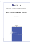
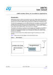
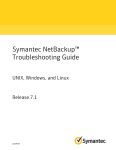
The CEC transaction is made up of a start bit, a 10-bit header and a sequence of n 10-bit
data blocks. The Header block and the Data blocks each contain an end-of-message (EOM)
bit and an acknowledge (ACK) bit. Figure 1 shows a CEC frame format.
Figure 1.
CEC frame
10 bits
10 bits
Start bit
10 bits
Data bock 1
Header block
Data block n
Example of Header block:
Example of Data block:
Initiator address = 0x6
Destination address = 0xD
Data = 0xE5
Header block
Data block
0
-
1 1 1 0 0 1 0 1
0
-
EOM
ACK
Data
EOM
ACK
0 1 1 0 1 1 0 1
Initiator
Destination
ai15931
A Header block is a sequence of 10 bits: the 4-bit logical address of the Initiator, the 4-bit
logical address of the Destination, the end-of-message (EOM) bit and the Acknowledge
(ACK) bit.
A Data block is a sequence of 10 bits: an 8-bit field that represents the opcode or the
operand, the end-of-message (EOM) bit and the Acknowledge (ACK) bit. The HDMI
standard defines the opcodes and the possible number of operands for each message.
2.2
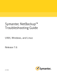
Hardware considerations
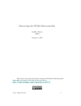
The physical connection to the HDMI network is straightforward. In accordance with the
CEC specification, the CEC pin of the HDMI connector has to be pulled up to a 3.3 V supply
voltage via a 27 kΩ resistor (refer to Figure 2).
Figure 2.
CEC Hardware requirement
3.3 V
27 kΩ
CEC device 2
CEC device 1
CEC device n
GND
ai15932
7/23
CEC library functions
3
UM0685
CEC library functions
The CEC library provides three types of functions:
●
Low level functions: functions that initialize and configure peripherals to be ready for
CEC communication.
●
Medium level functions: functions doing elementary CEC routines.
●
High level functions: functions sending/receiving CEC frames.
3.1
CEC low level functions
3.1.1
CEC_Init function
Table 2 describes the CEC_Init function.
Table 2.
CEC_Init function
Function name
CEC_Init
Prototype
void CEC_Init(void)
Behavior description
Initializes the GPIO, system tick, NVIC and EXTI to communicate with the
CEC protocol
Input parameter
None
Output parameter
None
Return parameter
None
Required preconditions
The software has to configure the different clocks and the NVIC vector
table base before calling this function.
Example
void NVIC_Configuration(void)
{
NVIC_InitTypeDef NVIC_InitStructure;
#ifdef VECT_TAB_RAM
/* Set the Vector Table base location to 0x20000000 */
NVIC_SetVectorTable(NVIC_VectTab_RAM, 0x0);
#else /* VECT_TAB_FLASH */
/* Set the Vector Table base location to 0x08000000 */
NVIC_SetVectorTable(NVIC_VectTab_FLASH, 0x0);
#endif
/* Configure two bits for preemption priority */
NVIC_PriorityGroupConfig(NVIC_PriorityGroup_2);
}
int main(void)
{
/* RCC configuration */
RCC_Configuration();
8/23
UM0685
CEC library functions
/* NVIC configuration */
NVIC_Configuration();
/* CEC initialization */
CEC_Init();
....
....
}
3.1.2
CEC_NVIC_Configuration function
Table 3 describes the CEC_NVIC_Configuration function.
Table 3.
CEC_NVIC_Configuration function
Function name
CEC_NVIC_Configuration
Prototype
void CEC_NVIC_Configuration(void)
Behavior description
Configures global interrupts of SystemTick and EXTI
Input parameter
None
Output parameter
None
Return parameter
None
Required preconditions
The SystemTick and EXTI global interrupt priorities used in the CEC library
have to have the highest interrupt level in the application.
The used and reserved NVIC configurations for the CEC library are:
SystemTick: Preemption priority = 1, subpriority = 1
EXTI0: Preemption priority = 2, subpriority = 1
3.1.3
CEC_Wait100us function
Table 4 describes the CEC_Init function.
Table 4.
CEC_Wait100us function
Function name
3.1.4
CEC_Wait100us
Prototype
void CEC_Wait100us(vu32 nTime)
Behavior description
Insert a delay in 100 µs unit.
Input parameter
nTime is the number of 100 µs units to be inserted. Delay = 100 µs ×
nTime
Output parameter
None
Return parameter
None
Required preconditions
None
CEC_TimingDelay_Decrement function
Table 5 describes the CEC_TimingDelay_Decrement function.
9/23
CEC library functions
Table 5.
UM0685
CEC_TimingDelay_Decrement function
Function name
CEC_TimingDelay_Decrement
Prototype
void CEC_TimingDelay_Decrement(void)
Behavior description
Decrements the TimingDelay variable in the SysTick interrupt
Input parameter
None
Output parameter
None
Return parameter
None
Required preconditions
None
3.2
CEC medium level functions
3.2.1
CEC_SendStartBit function
Table 6 describes the CEC_SendStartBit function.
Table 6.
CEC_SendStartBit function
Function name
3.2.2
CEC_SendStartBit
Prototype
void CEC_SendStartBit(void)
Behavior description
Sends the CEC start bit.
Input parameter
None
Output parameter
None
Return parameter
None
Required preconditions
None
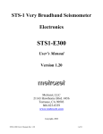
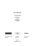
CEC_ReceiveStartBit function
Table 7 describes the CEC_ReceiveStartBit function.
Table 7.
CEC_ReceiveStartBit function
Function name
10/23
CEC_ReceiveStartBit
Prototype
u8 CEC_ReceiveStartBit(void)
Behavior description
Receives the CEC start bit.
Input parameter
None
Output parameter
None
Return parameter
a u8 integer:
1: if the CEC start bit has been received correctly
0: if the CEC start bit has not been received correctly
Required preconditions
None
UM0685
CEC library functions
Figure 3.
Receive start bit flowchart
Begin
No
Rising edge
?
wait 100 µs
Yes
CEC_counter <
35? (3.5 ms)
Yes
CEC_counter++
No
No
CEC_counter >
39? (3.9 ms)
Falling edge
?
wait 100 µs
No
Yes
Yes
Yes
CEC_counter <
43? (4.3 ms)
CEC_counter++
No
No
CEC_counter >
47? (4.7 ms)
Exit and return Success
Exit and return Error
Yes
Exit and return Error
ai15933
3.2.3
CEC_SendAckBit function
Table 8 describes the CEC_SendAckBit function.
Table 8.
CEC_SendAckBit function
Function name
3.2.4
CEC_SendAckBit
Prototype
void CEC_SendAckBit(void)
Behavior description
Sends the CEC ACK bit (ACK = logical 0)
Input parameter
None
Output parameter
None
Return parameter
None
Required preconditions
None
CEC_ReceiveAckBit function
Table 9 describes the CEC_ReceiveAckBit function.
Table 9.
CEC_ReceiveAckBit function
Function name
CEC_ReceiveAckBit
Prototype
u8 CEC_ReceiveAckBit(void)
Behavior description
Receives the CEC ACK bit
Input parameter
None
11/23
CEC library functions
Table 9.
UM0685
CEC_ReceiveAckBit function (continued)
Function name
3.2.5
CEC_ReceiveAckBit
Output parameter
None
Return parameter
a u8 integer:
0: receive ACK bit succeeded
0xFF: receive ACK bit failed
Required preconditions
None
CEC_SendDataBit function
Table 10 describes the CEC_SendDataBit function.
Table 10.
CEC_SendDataBit function
Function name
3.2.6
CEC_SendDataBit
Prototype
void CEC_SendDataBit(u8 bit)
Behavior description
Receives the CEC ACK bit (ACK = logical 0)
Input parameter
None
Output parameter
None
Return parameter
a u8 integer:
0: receive ACK bit succeeded
0xFF: receive ACK failed
Required preconditions
None
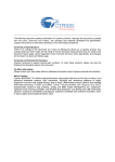
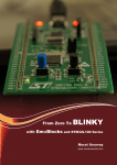
CEC_ReceiveDataBit function
Table 11 describes the CEC_ReceiveDataBit function.
Table 11.
CEC_ReceiveDataBit function
Function name
12/23
CEC_ReceiveDataBit
Prototype
u8 CEC_ReceiveDataBit(void)
Behavior description
Receives a CEC data bit.
Input parameter
None
Output parameter
None
Return parameter
The received data bit as a u8 integer:
1: if the data bit received was logical 1
0: if the data bit received was logical 0
0xFF: if the data bit has not been received correctly
Required preconditions
None
UM0685
CEC library functions
Figure 4.
Receive data bit flowchart
Begin
No
Rising edge
?
wait 100µs
Yes
No
CEC_counter++
CEC_counter >
13? (1.3 ms)
Yes
CEC_counter >
17? (1.7 ms)
bit = 0
Yes
CEC_counter >
8? (0.8 ms)
No
Yes
No
No
CEC_counter >
4? (0.4 ms)
Yes
bit = 1
Falling edge
?
No
wait 100 µs
Yes
CEC_counter <
20? (2 ms)
Yes
CEC_counter++
No
CEC_counter >
27? (2.7 ms)
Exit and return bit value
No
Yes
Exit and return Error
ai15934
3.2.7
CEC_SendByte function
Table 12 describes the CEC_SendByte function.
Table 12.
CEC_SendByte function
Function name
CEC_SendByte
Prototype
ErrorStatus CEC_SendByte(u8 byte)
Behavior description
Sends a CEC Header or Data block
Input parameter
byte: the CEC opcode or operand to be transmitted
Output parameter
None
Return parameter
The status of the Header/Data block transmission:
SUCCESS: CEC byte was acknowledged by the destination
ERROR: CEC byte wasn’t acknowledged by the destination
Required preconditions
None
13/23
CEC library functions
3.2.8
UM0685
CEC_ReceiveByte function
Table 13 describes the CEC_ReceiveByte function.
Table 13.
CEC_ReceiveByte function
Function name
CEC_ReceiveByte
Prototype
u8 CEC_ReceiveByte(u8 HeaderDataIndicator)
Behavior description
Receives a CEC Header or Data block
Input parameter
HeaderDataIndicator: indicates if the byte to receive is a Header or Data
block. It can be:
HeaderBlock: for the Header block reception
DataBlock: for the Data block reception
Output parameter
None
Return parameter
The received byte
Required preconditions
None
3.3
CEC high level functions
3.3.1
CEC_SendFrame function
Table 14 describes the CEC_SendFrame function.
Table 14.
CEC_SendFrame function
Function name
CEC_SendFrame
Prototype
ErrorStatus CEC_SendFrame(u8 InitiatorAddress, u8
FollowerAddress, u8 MessageLength, u8* Message)
Behavior description
Sends a CEC frame.
Input parameter
–
–
–
–
Output parameter
None
Return parameter
The status of the CEC frame transmission:
SUCCESS: If the destination received the full frame correctly
ERROR: the destination does not receive the full frame correctly
InitiatorAddress: the initiator address: from 0 to 15
FollowerAddress: the destination address: from 0 to 15
MessageLength: the number of data bytes to send
Message: a pointer to the transmit buffer
Required preconditions None
Example
#define MyDeviceAddress 0x6 /* My device address*/
#define FollowerAddress 0xF /* Follower address to send the frame */
u8 NumberOfTransmitAttempt = 5;
u8
TransmitBuffer[10]={0xdf,0x12,0xd3,0x56,0x97,0xa1,0xec,0x7b,0x4f,0x
22};
14/23
UM0685
CEC library functions
ErrorStatus SendStatus = ERROR;
/* Send the CEC frame */
do
{
SendStatus = CEC_SendFrame(MyDeviceAddress, FollowerAddress, 10,
TransmitBuffer);
waitOneSecond();
NumberOfTransmitAttempt--;
}
while ((SendStatus =! SUCCESS) || (!NumberOfTransmitAttempt));
3.3.2
CEC_ReceiveFrame function
Table 15 describes the CEC_ReceiveFrame function.
Table 15.
CEC_ReceiveFrame function
Function name
CEC_ReceiveFrame
Prototype
u32 CEC_ReceiveFrame(u8* Message, u8 FollLogAdd)
Behavior description
Receives a CEC frame
Input parameter
– Message: a pointer to the receive buffer
– FollLogAdd: the device address that will receive the frame: from 0 to 15
Output parameter
None
Return parameter
a u32 integer that contains some receive information (see below)
Required preconditions
Called by the EXTI interrupt routine
The contents of the u32 integer containing the CEC receive frame information returned by
CEC_ReceiveFrame function are:
31
30
29
28
27
26
15
14
13
12
11
10
25
24
23
22
21
20
19
18
7
6
5
4
3
2
always read as 0
9
8
NbRB [15:8]
Bits 31:18
17
16
FSTM
RFS
1
0
InitADD [7:0]
always read as 0.
Bit 17 FSTM: Frame sent to me
0: If the received frame does not have the same destination address
1: If the received frame has the same destination address
Bit 16 RFS: Receive frame status
0: The frame was not received correctly
1: The frame was received correctly
Bits 15:8 NbRB: Number of received bytes
This field contains the number of received data blocks.
15/23
CEC library functions
UM0685
Bits 7:0 InitADD: Initiator address
This field contains the frame sender address.
The FSTM, RFS and Initiator address masks are provided in the stm32f10x_cec.h file to
check their status:
#define ReceiveFrameStatusMask 0x00010000
#define FrameSendToMeMask
0x00020000
#define InitiatorAddressMask
0x000000FF
Example
●
In the stm32f10x.it.c file
#define MyDeviceAddress 0x6 /* My device address*/
/* Private variables ---------------------------------------------------*/
u8 ReceiveBuffer[10];
u8 ReceivedFrame = 0;
u32 ReceiveFrameInfos = 0;
/* Send the CEC frame */
void EXTI0_IRQHandler(void)
{
if(EXTI_GetITStatus(EXTI_Line0) != RESET)
{
/* Receive the CEC frame with my CEC address */
ReceiveFrameInfos = CEC_ReceiveFrame(ReceiveBuffer,
MyDeviceAddress);
/* Set ReceivedFrame software flag to say that a frame was
detected on the bus */
ReceivedFrame = 1;
/* Clear EXTI line 0 pending bit */
EXTI_ClearITPendingBit(EXTI_Line0);
}
}
●
In the main.c file
#include <stdio.h>
/* Private variables --------------------------------------------------*/
extern u8 ReceiveBuffer[10];
extern u8 ReceivedFrame;
extern u32 ReceiveFrameInfos;
u8 NbOfReceivedBytes = 0;
/* If a frame has been received */
if (ReceivedFrame)
{
/* Check if the frame has been received correctly */
if (ReceiveFrameInfos & ReceiveFrameStatusMask)
{
/* Check if the frame has been send to me */
if (ReceiveFrameInfos & FrameSendToMeMask)
16/23
UM0685
CEC library functions
{
/* Glow the green LED */
GlowGreenLED();
/* Get the number of received bytes */
NbOfReceivedBytes = (u8) (ReceiveFrameInfos >> 8);
/* Get the initiator address */
InitiatorAddress = (u8) (ReceiveFrameInfos &
InitiatorAddressMask);
printf("Initiator Address: %x\n", InitiatorAddress);
printf("Received data Frame: ", InitiatorAddress);
for(i=0;i<NbOfReceivedBytes;i++)
{
/* Display the received frame */
printf("%x ",ReceiveBuffer[i] );
}
}
else /* The receive was successful, but I'm not the concerned
destination */
{
/* Glow the yellow LED */
GlowYellowLED();
}
}
else /* The receive was failed */
{
/* Glow the red LED */
GlowRedLED();
}
}
ReceivedFrame=0;
}
17/23
How to run the CEC demo
4
UM0685
How to run the CEC demo
The demo provided with this user manual is intended to run on three STM3210B-EVAL
evaluation boards. It can be run on only two boards but, in this case, the send to the third
device is not achieved (refer to Figure 8).
The demo runs at 72 MHz. The CPU load for the 10-byte CEC receive or send frames over
15 seconds will be of around 2%.
4.1
Example of hardware connections between the three
evaluation boards
To run the CEC demo you have to connect the three evaluation boards as shown in
Figure 5. That is, you have to connect the board grounds together, then all the PA0 pins
together (they constitute the CEC bus). Finally, you have to connect a pull-up resistor
(27 kΩ) between the CEC bus and the 3.3 V power supply. The latter can be provided by any
of the boards.
Figure 5.
CEC connections between the three STM3210B-EVAL boards
3.3 V
27 kΩ
CEC bus
PA0
STM3210B-EVAL
CEC device with
address 0x1
PA0
STM3210B-EVAL
CEC device with
address 0x2
PA0
STM3210B-EVAL
CEC device with
address 0x3
VSS
VSS
VSS
ai15935
4.2
CEC demo guidelines
There are three folders in the CEC_Demo folder: 1rst_CEC_Device, 2nd_CEC_Device and
3rd_CEC_Device.
Each folder contains the project of a device that should be compiled and loaded into one
board. If only two boards are available, compile and load any pair (1st_Device, 2nd_Device),
(1st_Device, 3rd_Device) or (2nd_Device, 3rd_Device) to the first board and the second
board, respectively. Run the demo on each board and the LCD display shown in Figure 6
will appear.
Begin the send/receive transactions by pressing the “key” button on any board.
Example: if you are pressing the key button on the board with the address 0x1 (1st_Device),
this board will send a frame to the board with the address 0x2 (2nd_Device). The next time
you press on the “key” button, another frame will be sent to the board with the address 0x3
(3rd_Device).
18/23
UM0685
How to run the CEC demo
For more details refer to sections 4.3 and section 4.4.
If you are using another type of board, you can show the send/receive frame on the
toolchain live watch.
By default, the GPIO pin used for the CEC configuration is PA0. You can use another GPIO
pin by modifying some configuration in the CEC library: the used GPIO, the GPIO that
generates the EXTI interrupt and the NVIC IRQ channel. You also have to call the
CEC_ReceiveFrame function in the appropriate EXTI interrupt routine.
4.3
CEC send/receive information display on the LCD
The LCD screen is divided into two parts:
●
a subscreen that shows the CEC receive information
●
a subscreen that shows the CEC send information
After reset, each board displays the screen shown in Figure 6.
Figure 6.
LCD screenshot after reset
Subscreen showing
the receive information
Subscreen showing
the send information
ai15936
4.4
Send subscreen information
Figure 7 shows that the frame was received without error by the device with address 0x1.
The receiver has acknowledged the frame (0x25,0x36,0x79,0xDF,0xA1,0xBD, 0xEC, 0xAB,
0xFD, 0x58).
Figure 7.
LCD screenshot of a successful send transaction
The send transaction
to the device with
address 0x01
was successful
The destination
address = 01
Data transmitted
to the device with
address 01
ai15937
19/23
How to run the CEC demo
UM0685
In Figure 8 the frame (0xAA, 0x55,0x7E) was not sent to the intended destination (address
0x3). The frame is not acknowledged by the receiver.
Figure 8.
4.5
LCD screen shot of a failed send transaction
Receive subscreen information
Figure 9 shows that the device has correctly received the frame from the sender with
address 0x1. The data length (only data block) of the received frame is 0xA (10 bytes).
The received data are: 0xDF, 0x12, 0xD3, 0x56, 0x97, 0xA1, 0xEC, 0x7B, 0x4F, 0x22
Figure 9.
LCD screenshot of a successful receive transaction
Figure 10 shows that the device detected a frame on the bus coming from the device with
address 0x2, but it did not receive it because it is not the frame destination.
Figure 10. LCD screenshot of a detected frame
Figure 11 shows that an error has occurred while receiving the message.
Figure 11. LCD screenshot of a failed receive transaction
20/23
UM0685
5
Conclusion
Conclusion
This user manual describes the STM32F10xxx CEC library, which contains the basic
functions to communicate with the CEC protocol:
●
CEC_Init: CEC initialization.
●
CEC_SendStartBit: send CEC start bit.
●
CEC_ReceiveStartBit: receive CEC start bit.
●
CEC_SendAckBit: send CEC ACK bit (logical 0).
●
CEC_ReceiveAckBit: receive CEC ACK bit.
●
CEC_SendDataBit: send CEC data bit.
●
CEC_ReceiveDataBit: receive CEC data bit.
●
CEC_SendByte: send CEC Header/Data block
●
CEC_ReceiveByte: receive CEC Header/Data block
●
CEC_SendFrame: Send CEC frame with addressed messages.
●
CEC_ReceiveFrame: receive CEC frame with addressed messages.
21/23
Revision history
6
UM0685
Revision history
Table 16.
22/23
Document revision history
Date
Revision
06-Mar-2009
1
Changes
Initial release.
UM0685
Please Read Carefully:
Information in this document is provided solely in connection with ST products. STMicroelectronics NV and its subsidiaries (“ST”) reserve the
right to make changes, corrections, modifications or improvements, to this document, and the products and services described herein at any
time, without notice.
All ST products are sold pursuant to ST’s terms and conditions of sale.
Purchasers are solely responsible for the choice, selection and use of the ST products and services described herein, and ST assumes no
liability whatsoever relating to the choice, selection or use of the ST products and services described herein.
No license, express or implied, by estoppel or otherwise, to any intellectual property rights is granted under this document. If any part of this
document refers to any third party products or services it shall not be deemed a license grant by ST for the use of such third party products
or services, or any intellectual property contained therein or considered as a warranty covering the use in any manner whatsoever of such
third party products or services or any intellectual property contained therein.
UNLESS OTHERWISE SET FORTH IN ST’S TERMS AND CONDITIONS OF SALE ST DISCLAIMS ANY EXPRESS OR IMPLIED
WARRANTY WITH RESPECT TO THE USE AND/OR SALE OF ST PRODUCTS INCLUDING WITHOUT LIMITATION IMPLIED
WARRANTIES OF MERCHANTABILITY, FITNESS FOR A PARTICULAR PURPOSE (AND THEIR EQUIVALENTS UNDER THE LAWS
OF ANY JURISDICTION), OR INFRINGEMENT OF ANY PATENT, COPYRIGHT OR OTHER INTELLECTUAL PROPERTY RIGHT.
UNLESS EXPRESSLY APPROVED IN WRITING BY AN AUTHORIZED ST REPRESENTATIVE, ST PRODUCTS ARE NOT
RECOMMENDED, AUTHORIZED OR WARRANTED FOR USE IN MILITARY, AIR CRAFT, SPACE, LIFE SAVING, OR LIFE SUSTAINING
APPLICATIONS, NOR IN PRODUCTS OR SYSTEMS WHERE FAILURE OR MALFUNCTION MAY RESULT IN PERSONAL INJURY,
DEATH, OR SEVERE PROPERTY OR ENVIRONMENTAL DAMAGE. ST PRODUCTS WHICH ARE NOT SPECIFIED AS "AUTOMOTIVE
GRADE" MAY ONLY BE USED IN AUTOMOTIVE APPLICATIONS AT USER’S OWN RISK.
Resale of ST products with provisions different from the statements and/or technical features set forth in this document shall immediately void
any warranty granted by ST for the ST product or service described herein and shall not create or extend in any manner whatsoever, any
liability of ST.
ST and the ST logo are trademarks or registered trademarks of ST in various countries.
Information in this document supersedes and replaces all information previously supplied.
The ST logo is a registered trademark of STMicroelectronics. All other names are the property of their respective owners.
© 2009 STMicroelectronics - All rights reserved
STMicroelectronics group of companies
Australia - Belgium - Brazil - Canada - China - Czech Republic - Finland - France - Germany - Hong Kong - India - Israel - Italy - Japan Malaysia - Malta - Morocco - Singapore - Spain - Sweden - Switzerland - United Kingdom - United States of America
www.st.com
23/23