1
132
Detector Calibration
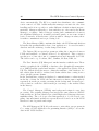
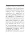
automation would be very complex if the data should be retrieved from the
permanent data storage, analyzed offline and then used to update the CDB.
Furthermore, in many calibrations methods, the triggers are generated by
the off-detector electronics hence the required trigger information needed for
the event building is missing.
Data
ALICE DAQ
Control
Detector Algorithms (DA)
a)
Standalone Runs
b)
Physics Runs
Monitor Machine
DA b
RO Electronics
DAQ Network
DAQ
FXS
DCS Network
FERO
CDB
General Purpose
Network
FXS-CDB
Connector
Offline Shuttle
(Pre-Processing)
Commands
& Status
FED
FED Servers
Servers
(x2)
(x2)
Local Data Collectors
(LDCs)
DA a
Reference
Data DB
OCDB
FERO Control
Reference Data
Displayer
FECS
Optical
Ethernet
VME
DIM
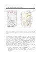
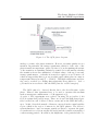
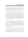
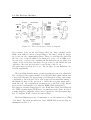
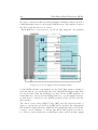
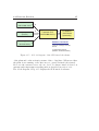
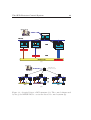
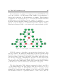
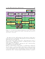
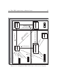
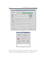
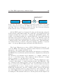
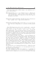
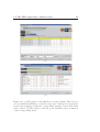
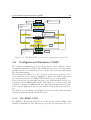
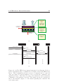
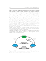
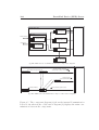
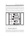
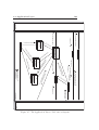
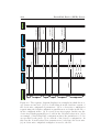
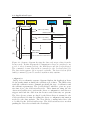
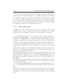
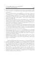
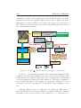
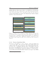
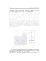
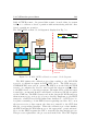
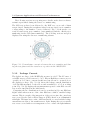
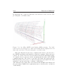
Figure 5.1: A DAQ ACTIVE calibration scenario block diagram.
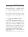
In order to cope with these specifications I foresaw that, during the SPD
calibration, the produced calibration raw data are stored locally in the SPD
LDCs and they are analyzed online at the end of each run. The event building
is as well suppressed during the SPD calibration. The DAQ configuration
swap between the physics data taking mode and the calibration mode is
performed, if needed, automatically by the ECS at the beginning of each
run.
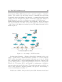
When the DAQ is ready for calibration data taking, the ECS sends to
the SPD FSM top-node the start calibration command. Using the command
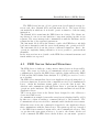
information, the top-node decides if the calibration to be performed is ei-