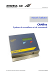
1
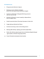
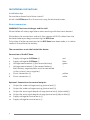
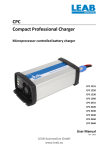
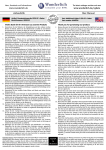
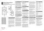
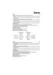
Battery control system DCC 6000
Description and Operating Instructions
User Manual
www.leab.eu
1
Dear customer,
You have acquired one of the finest battery control systems in the world –
the DCC 6000.
Please take note of the sizable screen, which at all times makes it easy to read the
displayed information.
In order to use your DCC 6000 effectively you will the need following
information.
Battery capacity – see battery.
The system’s voltage, 12 or 24 V DC – see battery.
To determine the effective range (shunt) you will need the maximum
values of charge and discharge current.
Charge factor – our experience shows in case of lead accumulation it is
usually at 95 %, with other batteries other values have to be taken into
account – see programming.
2
DCC 6000 Features
1.
Charge current indicator in Ampere
2. Discharge current indicator in Ampere
(with short term repository of maximum storage!)
3. Continuous indication of charge and discharge currents
with on-screen arrows
4. Indication of battery’s current capacity in Ampere hours;
both in number and %.
5. Graphic representation of the output by means of a bar chart
6. Supply voltage indicated at all times
7. Continuous warning as soon as low voltage occurs
8. Warning when battery capacity gets too low (adjustable)
9. Notice when battery capacity goes from critically low (deep discharge)
again reaches sufficient charge (adjustable)
10. Screen illumination (automatic deactivation)
3
Installation instructions
Installation tips
Do use the enclosed installation stencil!
Attach the DCC 6000 within the cut out using the enclosed screws.
Electric connection:
WARNING! Short-circuit danger and fire risk!
Please follow all safety regulations when working with electronic devices!
Write down the connections and only then remove all PLUS-cables from the
batteries before you begin connecting the DCC 6000.
Only when all other connections to the DCC 6000 have been made, is it safe to
reattach the cable to the battery.
The connections are in the back of the device:
Connection of the DCC 6000:
1. Supply voltage for DCC 6000 (+) red
2. Supply voltage for DCC 6000 (-) blue
3. Voltage measurement (+) (for second battery) green
4. Voltage measurement (-) (for second battery)
Both battery negative poles must be connected
in the system (=mass together)
–
5. Shunt connection (+) yellow
6. Shunt connection (-) white
Optional: Connections for control outputs:
7. Output for under voltage warning (control exit) (-)
8. Output for under voltage warning (control exit) (+)
9. Output for warning of deep discharge (control exit) (adjustable) (-)
10. Output for warning of deep discharge (control exit) (adjustable) (+)
11. Supply voltage for control exits (+)
12. Supply voltage for control exits (-)
4
Upon connecting the DCC 6000 the screen will shows the factory settings.
The discharge current is shown in the right upper field (A).
Provided user and loading equipment are switched off, if the value appears: 0 A.
Battery voltage is shown in the left area of the screen (V).
Below the ampere display you will find the ampere-hours shown, (ah).
The bar chart shows the battery charge in %.
Programming
Factory Setting:
Instrument shunt (Shunt):
Type 2: e.g., 60 A, 100 A, 200 A (1 mOhm)
Battery capacity: 100, Ah
Charge factor: 95 %
Warning signal: with 50 % of the battery capacity
Warning signal „stop”: with 80 % of the battery capacity
Peukert rating: 1.1
Start Programming:
In order to adjust the program to given circumstances, you must use the keys on
the right.
Operate the arrow keys (up and down) simultaneously (press).
On the screen the menu choices appear on the left side under P, here you can find
the reading by using the lower arrow key: P 2, which also gives you the choice of
looking at the operating tension.
5
P 2: Battery Voltage 12 V or 24 V [U-bt]
After activating the middle key: Set (gleaming) U-bt
Using the arrow keys you can choose the voltage, 12 V or 24 V (see technical data).
Once the desired setting is chosen, confirm it with the middle key.
The screen now indicates the chosen setting 12 V or 24 V, which are the operational
voltage of the installation.
In order to set the other programs please follow the same procedures.
Chose the desired menu point using the arrow keys, use middle key and
select the desired setting.
After choosing the setting, confirm with the middle key.
Call up other program settings as needed.
P 3: Shunt
Choose the type of shunt (see technical data).
P 4: Capacity (battery) [CAP]
To set the battery capacity, the capacity of your battery needs to be in
ampere-hours (look at model plate on battery).
P 5: Loading factor [CHA fa %]
Typically the following settings have to be adjusted with various battery types:
Lead-gel/solar batteries, approx. 95 to 98 %
Gen. lead-based batteries, approx. 90 to 95 %
NiCad batteries, approx. 80%
The charge is a compensation factor for the DCC 6000, so that it takes into account
the efficiency of your battery.
Batteries take up more energy to charge than they disperse.
The precise loading factor depends on type and use of the battery.
P 6: Adjusting of the alarm point while falling short the capacity border [AL on %]
By using the arrow key program in the setting at which capacity limit you want to
be warned in %.
When the capacity limit falls short the warning signal sets in and shows the
remaining capacity on the blinking bar graph.
It is activated with an open-collector-exit.
6
P 7: Setting the switch-off [AL OUT OF VISION %]
By using the arrow key program in the setting at which point the alarm signal
should be deactivated; when sufficient battery charge has been reached;
enter in %.
The bar graph stops blinking when the capacity limit is recharged; it now shows the
current battery capacity.
By the activating the control exit, this is deactivated.
After programming all your desired settings you can leave the menu by pressing
both arrow keys simultaneously (press briefly). You will see a YES on the screen
on the upper right side.
Press the middle key to confirm your setting. This concludes your programming
phase.
If you wish to make changes to the programming you have the ability to press the
lower arrow key (press) and discontinue to programming with “no”.
All settings revert to the prior state.
Ah-counter setting (reset)
This function is to be applied only if:
1. the DCC 6000 is used for the first time with the gauging battery
2. when there has been a capacity setting change under P 4
In order to wrap up the programming after afore mentioned changes, the DCC 6000
readings have to be adjusted as follows:
1. Operate the middle key and hold down,
2. then additionally press both arrow keys.
You will now see the reading in Ah, which you entered under P3 previously.
By using the middle key you will now see the reading: 100%, a bar graph also shows
100.0 %.
7
Operating Instructions
Upper arrow key:
Illumination:
The screen illumination is switched on and off by using the upper arrow key. If the
illumination remains on it automatically turns itself off after approx 20 minutes.
Lower arrow key:
By using this arrow key the reading changes to V (=Volt) on the second input. This is
how you can read the tension of a second battery.
Requirement: the battery systems have to be connected.
Middle key:
When using this key Ah-reading (rest capacity) switches go % rest capacity.
8
Technical Data
Supply voltage: 12 or 24 V DC
Current drain: without lighting <4 mA,
with lighting <6 mA
Metering capacity, depending on:
Shunt, 1: 0,002 – 50 A/0,001 – 999.90, Ah
Shunt, 2: 0.01 - 500 A / 0,001 – 999.90, Ah
Shunt, 3: 0.1 - 5000 A/0,001 – 9,999.0, Ah
Measuring procedures: Sigma delta, automatic comparison
Correction factor: Peukert: 1.1
Temp. area: - 20 ° C to 60 °C
Measuring accuracy: /-0,1 % /-2 Digit
Loading capacity of outputs: 100 mA
Screen: LCD, background lighting visible surface:
35.00 x 75.00 mm
Fitting dimensions: H 59.0 x B 140.0 x D 28.5
(with clips: 40.0 mm)
use the installation stencil
Outside dimension front screen: H 65.0 x B 145.0˘mm
Weight: 160 g
Note:
By interruption of the electricity supply all programmed settings remain and are
reinstated when the device is turned back on.
9
Installation template
10
Weitergabe sowie Vervielfältigung dieses Dokuments, Verwertung und Mitteilung seines Inhalts sind verboten,
soweit nicht ausdrücklich gestattet. Zuwiderhandlungen verpflichten zu Schadenersatz. Alle Rechte für den
Fall der Patent-, Gebrauchsmuster- oder Geschmacksmustereintragung vorbehalten.
LEAB Automotive GmbH
Ladegerät
grün
Starterbatterie
_
Bezeichnung
Klemme*
Ausgang für Unterspannungswarnung (Steuerausgang) (-)
7
Ausgang für Unterspannungswarnung (Steuerausgang) (+)
8
Ausgang für Warnung vor Tiefentladung (Steuerausgang einstellbar) (-)
9
Ausgang für Warnung vor Tiefentladung (Steuerausgang einstellbar) (+)
10
Versorgungsspannung für Steuer-Ausgänge (+)
11
Versorgungsspannung für Steuer-Ausgänge (-)
12
Anschluss Alarmausgänge (nur DCC 6000S)
* Terminal nur DCC 6000S ** Kabel nur DCC 6000
Bezeichnung
Klemme*
Kabelfarbe**
Versorgungsspannung für DCC 6000 (+)
1
rot
Versorgungsspannung für DCC 6000 (-)
2
blau
Spannungsmessung Zweitbatterie (+)
3
grün
Spannungsmessung Zweitbatterie (-)
4
Minuspole der beiden Batterien müssen in dem System verbunden sein
(=gemeinsame Masse)
Shunt-Anschluss, Verbraucherseite (+)
5
gelb
Shunt-Anschluss, Batterieseite (-)
6
weiß
Anschluss DCC 6000 und 6000S
*** Hinweis: Wir empfehlen, den Mess-Shunt in die Minusleitung zu verbauen,
um das Risiko eines Kurzschlusses mit der Fahrzeugmasse zu vermeiden.
Eine Montage im Pluszweig ist bei Bedarf ebenfalls möglich.
Generator
G
+
11
5 6
blau
_
7 8 9 10 11 12
Zusatzbatterie
weiß
gelb
Zust.
K
***
Änderung
CI
Name
Iglhaut
Iglhaut
(Oberfl.)
LEAB
Datum
Bearb. 07.08.08
Gepr. 07.05.11
Norm
(Zul. Abw.)
10
9
8
7
Ladegerät
Datum Name Ursprung
Beschalt. Shunt 15.10.14
Dokumentation
(Verwendungsbereich)
DCC 6000 S
1 2 3 4
rot
+
ohne
(Gewicht)
0kg
Art.-Nr.1402060000/1
Ersatz für:
Ersatz durch:
1
Blätter
Blatt
Beschaltung DCC 6000/6000S
(Werkstoff, Halbzeug)
(Rohteil-Nr)
(Modell- oder Gesenk-Nr)
Maßstab
Alarm Tiefentladung
Alarm Unterspannung
Verbraucher
www.leab.eu
LEAB Automotive GmbH
Thorshammer 6
24886 Busdorf
Germany
T +49 (0) 46 21 97 860-110
F +49 (0) 46 21 97 860-260
[email protected]
12
grün
Starterbatterie
Generator
Ladegerät
Verbraucher
Zusatzbatterie
Ladegerät
_
+
_
Weitergabe sowie Vervielfältigung dieses Dokuments, Verwertung und Mitteilung seines Inhalts sind verboten,
soweit nicht ausdrücklich gestattet. Zuwiderhandlungen verpflichten zu Schadenersatz. Alle Rechte für den
Fall der Patent-, Gebrauchsmuster- oder Geschmacksmustereintragung vorbehalten.
LEAB Automotive GmbH
+
G
***
gelb
blau
rot
weiß
7
Alarm Unterspannung
8
*** Hinweis: Wir empfehlen, den Mess-Shunt in die Minusleitung zu verbauen,
um das Risiko eines Kurzschlusses mit der Fahrzeugmasse zu vermeiden.
Eine Montage im Pluszweig ist bei Bedarf ebenfalls möglich.
Anschluss DCC 6000 und 6000S
1 2 3 4
5 6
7 8 9 10 11 12
9
Alarm Tiefentladung
DCC 6000 S
10
Bezeichnung
Klemme*
Kabelfarbe**
Versorgungsspannung für DCC 6000 (+)
1
rot
Versorgungsspannung für DCC 6000 (-)
2
blau
Spannungsmessung Zweitbatterie (+)
3
grün
Spannungsmessung Zweitbatterie (-)
4
Minuspole der beiden Batterien müssen in dem System verbunden sein
(=gemeinsame Masse)
Shunt-Anschluss, Verbraucherseite (+)
5
gelb
Shunt-Anschluss, Batterieseite (-)
6
weiß
* Terminal nur DCC 6000S ** Kabel nur DCC 6000
(Verwendungsbereich)
(Zul. Abw.)
(Oberfl.)
Dokumentation
Anschluss Alarmausgänge (nur DCC 6000S)
K
Bezeichnung
Klemme*
Ausgang für Unterspannungswarnung (Steuerausgang) (-)
7
Ausgang für Unterspannungswarnung (Steuerausgang) (+)
8
Ausgang für Warnung vor Tiefentladung (Steuerausgang einstellbar) (-)
9
Ausgang für Warnung vor Tiefentladung (Steuerausgang einstellbar) (+)
10
Versorgungsspannung für Steuer-Ausgänge (+)
11
Versorgungsspannung für Steuer-Ausgänge (-)
12
Zust.
Beschalt. Shunt 15.10.14
Änderung
Maßstab
ohne
(Werkstoff, Halbzeug)
(Rohteil-Nr)
(Modell- oder Gesenk-Nr)
CI
Datum
Bearb. 07.08.08
Gepr. 07.05.11
Norm
Name
Iglhaut
Iglhaut
LEAB
Datum Name Ursprung
(Gewicht)
0kg
Art.-Nr.1402060000/1
Beschaltung DCC 6000/6000S
Blatt
1
Blätter
Ersatz für:
Ersatz durch: