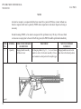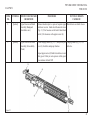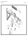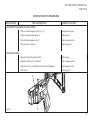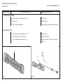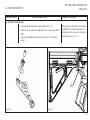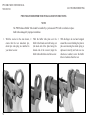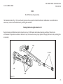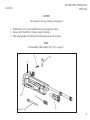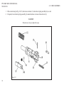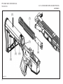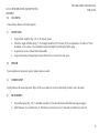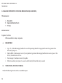
1
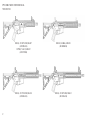
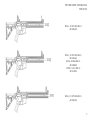
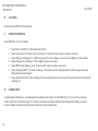
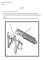
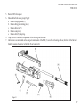
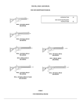
PWS MK1, MOD1 RIFLE SERIES USER MANUAL
END USER MAINTENANCE MANUAL
CHAPTER 1: INTRODUCTION
22
CHAPTER 2: END USER MAINTENANCE INSTRUCTIONS
34
APPENDIX A: CLEANING
84
- PUBLIC FOR COMMERCIAL RELEASE
PWS MK1 MOD1 USER MANUAL
VER 2015.01
2
RIFLE, .223 WYLDE, MK107
(M107RA1B)
UPPER, 7.62x39, MK107
(M107UF0B)
RIFLE, 300 BLK, MK109
(M109RB1B)
RIFLE, .223 WYLDE, MK110
(M110RA1B)
RIFLE, .223 WYLDE, MK112
(M112RA1B)
PWS MK1 MOD1 USER MANUAL
VER 2015.01
RIFLE, .223 WYLDE, MK114
(M114RA1B)
RIFLE, .223 WYLDE, MK116
(M116RA1B)
RIFLE, 300 BLK MK116
(M116RB1B)
UPPER, 7.62x39, MK116
(M116UF0B)
RIFLE, .223 WYLDE, MK118
(M118RA1B)
3
PWS MK1 MOD1 USER MANUAL
VER 2015.01
WARNING
ALL WARNINGS in this user and maintenance manual pertain to all versions of PWS rifles, carbines and uppers unless otherwise
specified.
Prior to beginning an inspection, ensure the rifle is UNLOADED. DO NOT pull the trigger until the rifle has been cleared. Remove the
magazine and inspect the chamber to ensure that it is empty and that a round is not chambered.
Do not keep live ammunition near work area.
To avoid injury, use caution when removing and installing spring-loaded components.
The bolt cam pin must be installed or irreparable damage will occur to the weapon and injury or death of personnel may result.
Cleaning solvents are flammable and toxic and should be used only in a well-ventilated area. The use of rubber gloves is necessary to
protect the skin when cleaning rifle parts.
Avoid skin contact when using carbon removing compounds. If carbon removing compound comes in contact with the skin, wash
thoroughly with running water. Using gloves and protective equipment is required.
4
PWS MK1 MOD1 USER MANUAL
VER 2015.01
CLEARING PROCEDURE
1. Orient the muzzle in a designated SAFE DIRECTION.
2. Attempt to place selector lever on SAFE (If weapon is not cocked, lever cannot be placed on SAFE).
3. Remove the magazine by depressing the magazine catch button and pulling the magazine away from the receiver.
4. Lock the bolt open by pull the charging handle rearward while pressing the bottom of bolt catch.
5. Ensuring the Bolt Carrier Group (BCG) is locked rearward, return the charging handle to full forward position.
6. If you have not done so before, place the selector lever on SAFE.
7. Visually (not physically) inspect the receiver and chamber to ensure these areas contain no ammunition.
8. Send the bolt forward on an empty chamber, by pressing the top of the bolt catch.
9. Close the ejection port cover.
5
PWS MK1 MOD1 USER MANUAL
VER 2015.01
Direct Support Maintenance Manual
For
RIFLE, .223 Wylde, MK107
(M107RA1B)
RIFLE, .223 Wylde, MK114
(M114RA1B)
UPPER, 7.62x39, MK107
(M107UF0B)
RIFLE, .223 Wylde, MK114 LE
(M114RA1BLE)
RIFLE, .223 Wylde, MK109
(M109RB1B
RIFLE, .223 Wylde, MK116
(M116RA1B)
RIFLE, .223 Wylde, MK110
(M110RA1B)
RIFLE, .300 BLK, MK116
(M116RB1B)
RIFLE, .223 Wylde, MK112
(M112RA1B)
UPPER, 7.62x39, MK116
(M116UF0B)
RIFLE, .300 BLK, MK112
(M112RB1B)
RIFLE, .223 Wylde, MK118
(M118RA1B)
Current as of January 2015
CONTENT ADOPTED FROM US ARMY TM 9-1005-319-23&P
6
PWS MK1 MOD1 USER MANUAL
VER 2015.01
CONTACT INFORMATION
If any further information or assistance is needed, always contact the PWS customer service support team:
E-mail: [email protected]
Phone: (208) 780-6122
Fax: (208) 297-2675
WARRANTY
PWS has a designated warranty department. If you are having any issues with any of our products, you believe your issue to be caused by
damage during shipping, or that it was caused by fault on our part (eg. missing parts), please report the damage immediately by filling out a
Warranty RMA Ticket online at www.primaryweapons.com.
WARRANTY INFORMATION
All components manufactured by Primary Weapons Systems Inc. (PWS) are warranted by the manufacturer for 24 months from the date of delivery, to its
customer against defects that may have occurred in the manufacturing process, during assembly, or during proofing of the product. The manufacturer also
guarantees the product functions to factory specifications and meets the quality standards as set by Primary Weapons Systems Inc., and will warranty any
product that fails to maintain those specifications.
This warranty shall include the replacement of any broken or worn parts that would render the carbines less than 100% safe and operable. The warranty shall
extend to weapons with damage as a result of normal operational wear and tear. The warranty only covers defects as specified herein and does not include
defects or damages related to use that exceeds the tolerances of the raw materials used in the product. Nor does it cover defects or damages attributable
to the installation or use of after-market or non-factory installed accessories beyond conventional sighting systems such as: optics, lasers, and white lights
to ensure long term reliability; misuse or normal surface wear; or defects or damages caused by neglect or by normal use within the scope of the intended
role and application of these products. These are subject to the customer following both the maintenance schedule and maintenance procedures as outlined
in both the User and Armorer’s Manuals for these components and products. And that the customer follows the intended use guidelines as specified by the
appropriate manual or instruction card. The warranty shall not extend to weapons damaged beyond repair through abuse caused by catastrophic conditions,
such as fire, and routine abuse such as accidental dropping. THIS WARRANTY WILL BE VOID IF THE PRODUCT HAS BEEN ALTERED BY THE
CUSTOMER OR THIRD PARTY; ABUSED OR MISUSED.
7
PWS MK1 MOD1 USER MANUAL
VER 2015.01
TABLE OF CONTENTS
CLEARING PROCEDURE
CONTACT INFORMATION
WARRANTY INFORMATION
SAFETY WARNINGS
FIREARM USE WARNING
USED FIREARM DISCLAIMER
GENERAL INFORMATION
BARREL LIFE
APPEARANCE AND RECEIVER FIT
MODIFICATION WARNING
HOW TO USE THIS MANUAL
GENERAL
INDEXES
MAINTENANCE PROCEDURES
EXTERNAL VIEW OF THE MK1 SERIES RIFLE
CHAPTER 1
Section I. GENERAL INFORMATION
1-1 SCOPE
Section II. EQUIPMENT DESCRIPTION AND DATA
1-2 EQUIPMENT CHARACTERISTICS, CAPABILITIES, AND FEATURES
8
5
7
7
12
15
16
16
16
17
17
18
18
19
19
20
22
22
22
22
22
PWS MK1 MOD1 USER MANUAL
VER 2015.01
1-3 LOCATION AND DESCRIPTION OF MAJOR COMPONENTS
1-4 EQUIPMENT DATA
Section III. PRINCIPLES OF OPERATION
1-5 GENERAL
1-6 PRINCIPLES OF OPERATION
CHAPTER 2
END USER MAINTENANCE INSTRUCTIONS
Section I. REPAIR PARTS AND SUPPORT EQUIPMENT
2-1 COMMON TOOLS AND EQUIPMENT
2-2 SPECIAL TOOLS AND SUPPORT EQUIPMENT
Section II. SERVICE UPON RECEIPT
2-3 GENERAL
2-4 SERVICE UPON RECEIPT OF MATERIAL
Section III. PREVENTATIVE MAINTENANCE CHECKS AND SERVICES (PMCS)
2-5 GENERAL
2-6 PREVENTATIVE MAINTENCE CHECKS AND SERVICES
Section IV. TROUBLESHOOTING
2-7 GENERAL
2-8 TROUBLESHOOTING PROCEDURES
GAS ADJUSTMENT SETTINGS
1. FAILURE OF MAGAZINE TO LOCK IN RIFLE
24
26
32
32
32
34
34
34
34
34
35
35
35
37
37
37
47
47
47
49
51
9
PWS MK1 MOD1 USER MANUAL
VER 2015.01
2. FAILURE TO FEED
3. FAILURE TO CHAMBER
4. FAILURE TO LOCK
PWS ENHANCED BUFFER TUBE INSTALLATION INSTRUCTIONS
5. FAILURE TO FIRE
6. FAILURE TO UNLOCK
7. FAILURE TO EXTRACT
8. FAILURE TO EJECT
9. FAILURE TO COCK
10. SHORT RECOIL/SHORT STROKING
11. RIFLE CANNOT BE ZEROED
12. FIRES TWO ROUNDS WITH ONE PULL OF THE TRIGGER WITH SELECTOR ON SEMI (DOUBLE
FIRING)
13. FIRES WITH SELECTOR LEVER ON SAFE OR WHEN TRIGGER IS RELEASED WITH SELECTOR ON
SEMI
14. BOLT ASSEMBLY FAILS TO LOCK TO REAR AFTER FIRING LAST ROUND
15. FAILURE TO CYCLE WITH SELECTOR LEVER ON AUTO (SELECT-FIRE) ONLY
Section V. MAINTENANCE PROCEDURES
2-9 INITIAL SETUP
2-10 LUBRICATION GENERAL
2-11 MAJOR COMPONENTS OF THE MKI SERIES RIFLES
10
51
52
52
54
57
58
58
58
58
60
60
60
60
61
61
62
62
62
64
PWS MK1 MOD1 USER MANUAL
VER 2015.01
2-12 BOLT CARRIER GROUP (BCG)
2-13 BOLT ASSEMBLY
2-14 UPPER RECEIVER AND BARREL ASSEMBLY
2-15 LOWER RECEIVER AND BUTTSTOCK ASSEMBLY
2-16 MAJOR COMPONENTS OF THE MK1 SERIES RIFLES
APPENDIX A
CLEARING PROCEDURE
CLEANING
66
71
74
77
80
84
85
86
11
PWS MK1 MOD1 USER MANUAL
VER 2015.01
SAFETY IS YOUR NUMBER ONE RESPONSIBILITY
Regardless of where you are, the first concern of every firearm owner should be safety. Apply the following safety rules in every situation
and with any kind of firearm. If you feel uncertain about any operational aspects of your firearm, please contact Primary Weapons
Systems, Inc. (PWS) customer service at (208) 780-6122 before proceeding with its operation.
SAFETY WARNINGS
YOU MUST FOLLOW ALL SAFETY RULES TO ENSURE THE SAFE USE OF YOUR FIREARM. FAILURE TO FOLLOW THE
INSTRUCTIONS AND WARNINGS IN THIS MANUAL COULD CAUSE SERIOUS PERSONAL INJURY OR DEATH TO YOU OR
OTHERS AND DAMAGE TO PROPERTY.
As a gun owner, you accept a demanding responsibility. How seriously you take this responsibility can be the difference between life and
death. There is no excuse for careless or abusive handling of your firearm. Handle your firearm with extreme respect for its power and
potential danger.
ALWAYS KEEP YOUR FIREARM POINTED IN A SAFE DIRECTION
Never point a firearm at anyone or anything you do not intend to destroy whether it is or is not loaded. This is particularly important when
loading, unloading, or field stripping the firearm.
ALWAYS control the direction of the firearm.
NEVER stick any product made by Primary Weapons Systems in your anal cavity. Rectal insertion of any of our products can cause
irreparable damage to both your rectum and your high quality firearm accessory.
12
PWS MK1 MOD1 USER MANUAL
VER 2015.01
ALWAYS TREAT EVERY FIREARM AS IF IT IS LOADED AND WILL FIRE
Do not take someone’s word that the firearm is unloaded – always check it yourself. Never pass your firearm to another person until the
cylinder or action is open and you visually check that it is unloaded. Keep your firearm unloaded and safely stored when not in use.
NEVER PLACE YOUR FINGER INSIDE THE TRIGGER GUARD OR ON THE TRIGGER UNLESS YOU INTEND TO FIRE
Ensure that other objects do not touch the trigger.
ALWAYS BE SURE OF YOUR TARGET AND WHAT IS BEYOND IT
Always be sure of where the bullet will strike and shoot only where there is a safe back stop free of obstructions, water or other surfaces
that can cause ricochets. Be sure your bullet will stop behind your target. Bullets can ricochet and travel in unpredictable directions with
considerable velocity. Do not fire randomly into the sky.
ALWAYS WEAR EYE AND EAR PROTECTION THAT IS SPECIFIED FOR USE WITH FIREARMS
Proper protective equipment should be worn every time you handle your firearm for purposes of discharging your firearm or for cleaning
and maintenance. Ensure that others in the vicinity of where you are shooting also wear proper ear and eye protection.
NEVER USE ALCOHOL OR DRUGS BEFORE OR WHILE SHOOTING
Do not use your firearm if you are under the influence of a substance or medication that impairs your mental or physical abilities.
ALWAYS HAVE ADEQUATE VENTILATION
Discharging firearms in poorly ventilated areas, cleaning firearms, or handling ammunition may result in exposure to lead and other
substances known to cause birth defects, reproductive harm, and other serious physical illness. Review the warnings and labels for all
ammunition and cleaning products carefully. Wash hands thoroughly after exposure.
13
PWS MK1 MOD1 USER MANUAL
VER 2015.01
BEFORE HANDLING ANY FIREARM, UNDERSTAND ITS OPERATION
Not all firearms are the same. Familiarize yourself with the mechanical features of any firearm you intend to use. If you feel uncertain
about any operational aspects of your PWS firearm, please contact PWS Customer Service at (208) 780-6122 before proceeding with its
operation.
NEVER ALLOW A FIREARM TO BE USED BY INDIVIDUALS WHO DO NOT UNDERSTAND ITS SAFE OPERATION OR HAVE
NOT READ THESE FIREARM SAFETY RULES
ALWAYS USE THE CORRECT AMMUNITION FOR YOUR PARTICULAR FIREARM
Never use non-standard, reloaded, or “hand loaded” ammunition that has not been subjected to internal ballistic pressure testing.
BEWARE OF BARREL OBSTRUCTIONS
Be sure the barrel is clear of obstructions before shooting. Mud, water, snow or other objects may inadvertently lodge in the barrel bore. A
small obstruction can cause a dangerous increase in pressure and may damage your weapon and cause injury to yourself and others.
ENSURE ALL ACCESSORIES ARE COMPATIBLE
Ensure that all accessories such as grips, slings, scopes and other accessories are compatible with the firearm and that the accessories do
not interfere with safe operation. It is your responsibility to understand and follow all of the instructions in this manual, as well as those
that may be supplied with your ammunition and any accessory.
NEVER DISASSEMBLE YOUR FIREARM BEYOND THE FIELD STRIPPING PROCEDURE OUTLINED IN THIS MANUAL
Improper disassembly or reassembly of your firearm may be dangerous and can lead to serious injury or death.
14
PWS MK1 MOD1 USER MANUAL
VER 2015.01
NEVER MANIPULATE, ADJUST OR CHANGE ANY OF THE INTERNAL COMPONENTS OF YOUR FIREARM UNLESS
SPECIFICALLY INSTRUCTED TO DO SO IN THIS MANUAL
Improper manipulation of any other internal component may affect the safety and reliability of your firearm and may cause serious injury
or death.
NEVER ALLOW ANY ALTERATION OR REPLACEMENT OF PARTS IN YOUR PWS FIREARM UNLESS PERFORMED BY A
QUALIFIED GUNSMITH
Repairs or replacements should only be done by a qualified gunsmith using genuine PWS parts. If you do otherwise, improper functioning
of your firearm may occur and serious injury or death and damage to property may result.
FIREARM USE WARNING
SAFE USE OF A FIREARM IS YOUR PERSONAL RESPONSIBILITY AND THE FAILURE TO FOLLOW ALL OF THESE BASIC
SAFETY RULES MAY RESULT IN SEVERE PERSONAL INJURY OR DEATH TO YOU OR OTHERS AND DAMAGE TO PROPERTY.
YOU ARE THE MOST IMPORTANT SAFETY DEVICE WHEN IT COMES TO THE USE OF YOUR FIREARM. PRIMARY WEAPONS
SYSTEMS, INC WILL NOT BE RESPONSIBLE FOR ANY PERSONAL INJURY, DEATH OR PROPERTY DAMAGE THAT RESULTS
FROM: (1) THE CRIMINAL OR NEGLIGENT USE OF THIS FIREARM; (2) A DISREGARD OF THESE SAFETY INSTRUCTIONS
AND WARNINGS; (3) IMPROPER OR CARELESS HANDLING OF THIS FIREARM; (4) THE USE OF NON-STANDARD,
DEFECTIVE, IMPROPER OR RELOADED AMMUNITION; OR (5) IMPROPER OR NEGLIGENT MODIFICATIONS OR REPAIRS
TO THE FIREARM.
15
PWS MK1 MOD1 USER MANUAL
VER 2015.01
USED FIREARM DISCLAIMER
BUYER AGREES TO HAVE ANY USED FIREARM CHECKED BY A CERTIFIED GUNSMITH PRIOR TO FIRING. BUYER
ASSUMES ALL LEGALITY, LIABILITY AND RESPONSIBILITY FOR THE CONDITION, USE AND SECURITY/STORAGE OF
THE PURCHASED FIREARM. BUYER UNDERSTANDS THAT ALL FIREARMS ARE POTENTIALLY DANGEROUS IF HANDLED
IMPROPERLY. UPON PURCHASE, BUYER ASSUMES ALL LIABILITY AND RESPONSIBILITY INCLUDING BUT NOT LIMITED
TO THE USAGE AND SAFE STORAGE OF THE PURCHASED FIREARM.
GENERAL INFORMATION
Your firearm is a lightweight, gas piston-operated, air cooled, magazine-fed rifle produced for a high degree of accuracy, reliability, and
durability. The firearm’s construction features extensive use of aircraft-grade forgings, CNC-machined components and high-quality barrels.
The unique design of this system has numerous benefits over the traditional direct-impingement system, as well as other gas piston-operated
AR-15 based platforms.
BARREL LIFE
Barrel life depends on how fast the rifle is fired and how accurate the shooter insists it must be. Firing the rifle as fast as the trigger can be
pulled or sustained full-auto fire can ruin the barrel in just a few hundred rounds. Firing at controlled rates, both semi-auto and burst, will
allow your barrel to last for 5,000 to 10,000 rounds with acceptable accuracy levels. As with any quality barrel, a proper barrel break-in will
ensure your new PWS product is as accurate as possible and proper maintenance will help your product last much longer. PWS recommends
you clean your rifle or upper at least every 1,000 rounds.
16
PWS MK1 MOD1 USER MANUAL
VER 2015.01
APPEARANCE AND RECEIVER FIT
Your new rifle is not a custom firearm. PWS requires a close fit between the receivers, but normal forging and machining variations may
result in play or slight side to side receiver mismatch. This is not a manufacturing defect and has no adverse effect on accuracy or the
weapon’s function. All PWS rifles and uppers are test-fired before leaving our facility. New rifles will normally show evidence of this firing.
If the receiver looks light or uneven in color, it is most likely dry and a light coat of oil on the metallic surfaces will improve its appearance.
The upper and lower receivers are made from forgings because forgings provide superior strength over billet machining processes. By the
very nature of a forging, small dents and dings on the outside of the receiver may be visible. No forging is free of them. This is not a defect.
MODIFICATION WARNING
YOUR PWS FIREARM WAS DESIGNED TO FUNCTION PROPERLY WITH ITS ORIGINAL COMPONENTS FROM THE FACTORY.
ALTERATIONS TO THE ORIGINAL COMPONENTS OR REPLACEMENT OF THEM WITH AFTERMARKET (NON-PWS
MANUFACTURED) COMPONENTS CAN CAUSE MALFUNCTIONS OR EVEN MAKE THE FIREARM UNSAFE. DO NOT ALTER
ANY PART OR ADD /SUBSTITUTE PARTS NOT MANUFACTURED BY PRIMARY WEAPONS SYSTEMS, INC. ATTEMPTED
CUSTOMIZATION OF YOUR PWS PRODUCT MAY VOID YOUR WARRANTY.
17
PWS MK1 MOD1 USER MANUAL
VER 2015.01
HOW TO USE THIS MANUAL
Please read this manual carefully before performing any maintenance. This manual must be referred to for all inspection, maintenance and
repair procedures.
GENERAL
There are several things you need to know to use this manual efficiently and effectively:
1. All references in the manual are to pages only. Reference to maintenance procedures is to the page where the respective initial setup
appears.
2. Illustrations for the maintenance procedures show only those parts affected by the operation being performed.
3. When a procedure is common to MK1 series rifles, ONLY the MK112 configuration will be depicted. If a selected procedure is not
common to all models of the MK1 series, separate procedures will be illustrated.
4. When the word rifle is referenced in text, it will reference the rifle and the carbines.
18
PWS MK1 MOD1 USER MANUAL
VER 2015.01
INDEXES
This manual is organized to help you find the information you need quickly. There are several useful indexes.
1. Table of Contents – lists all chapters, sections, and appendices along with the referenced pages
2. Chapter Overviews – Summarizes material covered in the chapter at the beginning of each chapter
3. Symptom Index – lists, in alphabetical order, parts of the rifle with possible malfunctions. Located just before the troubleshooting
table in each maintenance chapter
MAINTENANCE SECTIONS
There are three maintenance sections: Section III - Preventive Maintenance Checks and Services (PMCS), Section IV - Troubleshooting,
and Section V - Maintenance Procedures.
Each maintenance section provides a comprehensive list of instructions necessary to perform maintenance services on your firearm:
1. Section III: PMCS (page 37) – contains the procedures and instructions necessary to perform preventive maintenance checks and
services.
2. Section IV: Troubleshooting – contains troubleshooting information for locating and correcting most of the operating troubles which
may develop in the MK1 Series rifle.
3. Section V: Maintenance Procedures – contains information necessary to properly assemble, disassemble, and care for your firearm.
19
PWS MK1 MOD1 USER MANUAL
VER 2015.01
EXTERNAL VIEW OF THE MK1 SERIES RIFLE
RIGHT SIDE
20
PWS MK1 MOD1 USER MANUAL
VER 2015.01
LEFT SIDE
21
PWS MK1 MOD1 USER MANUAL
VER 2015.01
CHAPTER 1
INTRODUCTION
CHAPTER OVERVIEW
This chapter contains general information, equipment description and data, and principles of operation for the MK1 MOD1 series rifle.
Section I. GENERAL INFORMATION
1-1 SCOPE
1. Type of Manual - End Use and Maintenance
2. Model Number and Equipment name - MK107, MK109, MK110, MK112, MK114, MK116 and MK118 rifles
3. Purpose of Equipment - Provides user an offensive/defensive capability with small arms fire
Section II. EQUIPMENT DESCRIPTION AND DATA
1-2 EQUIPMENT CHARACTERISTICS, CAPABILITIES, AND FEATURES
A.Characteristics
22
a.
b.
c.
Light weight
Air-cooled
Gas-piston operated
d. Magazine-fed
e. Semiautomatic or select-fire
1-2.1 EQUIPMENT CHARACTERISTICS,
CAPABILITIES, AND FEATURES
B. Capabilities
PWS MK1 MOD1 USER MANUAL
VER 2015.01
Provides user an offensive and/or defensive capability to engage targets with direct small-arms fire.
C.
Features
1. The MK1 series is a significant product improvement for M4/M16-type carbines and rifles. Utilizing a long-stroke piston system, the
MK1 series greatly reduces fouling in the action of the weapon making it as reliable as the AK47 it was designed after.
2. Receivers are made of T7075 Forgings to ensure safety, durability, and function of the rifles while keeping weight and cost at a
minimum.
3. The handguard system features the VLTOR KeyMod™ system which comes standard with two 2-inch 1913 Picatinny rail sections as
well as a continuous 1913 Picatinny top rail.
4. The operating system utilizes an operating rod attached to the bolt carrier and a floating piston head attached to the operating rod.
With only one moving assembly, the system is simple, rugged and versatile with less parts to wear and replace.
5. Chromoly steel, Arcor® salt-bath treated, button-rifled barrels* deliver unmatched accuracy and performance.
23
PWS MK1 MOD1 USER MANUAL
VER 2015.01
1-3 LOCATION AND DESCRIPTION OF MAJOR COMPONENTS
(See Figure 1.1)
1. MAGAZINE 30 round capacity.
2. BOLT CARRIER GROUP (BCG) Carries bolt assembly to chamber and fires the weapon. Contains the bolt, firing pin, cartridge
extractor, cartridge ejector, firing pin retaining pin, bolt return spring and bolt cam pin.
3. CHARGING HANDLE ASSEMBLY Provides a means of charging the weapon.
4. UPPER RECEIVER AND BARREL ASSEMBLY Upper receiver contains: ejection port, ejection port cover, housing for key,
BCG and bolt assembly, and Picatinny rail. Rifle barrel assembly is air-cooled and contains the trunnion, gas block, piston tube,
handguard, compensator or flash hider, and QD sling swivel points.
5. LOWER RECEIVER AND BUTTSTOCK ASSEMBLY Lower receiver contains the trigger assembly, sear (select-fire only), hammer
assembly, selector lever, rifle grip, bolt catch, magazine catch, and buttstock assembly. The buttstock assembly houses the action
spring, buffer assembly, and buffer tube (receiver extension).
6. ADJUSTABLE GAS BLOCK The 4-position adjustable gas block allows the user to adjust for standard ammo (position 1*), high
pressure ammo (position 2), suppressed with standard ammo (position 3) and suppressed with military ammo (position 4). The
X-setting is for removal of the knob for annual maintenance. (See page 49)
24
*For normal unsuppressed use, position 1 is the most recommended setting.
PWS MK1 MOD1 USER MANUAL
VER 2015.01
Figure 1.1
25
PWS MK1 MOD1 USER MANUAL
VER 2015.01
1-4 EQUIPMENT DATA
US CUSTOMARY
METRIC
MK107, .223 Wylde & 7.62x39 without magazine
5 lbs, 13 oz
2.34 kg
MK109, .300 BLK without magazine
6 lbs, 1 oz
2.75 kg
MK110, .223 Wylde without magazine
6 lbs, 3 oz
2.79 kg
MK112, .223 Wylde without magazine
6 lbs, 6 oz
2.91 kg
MK114, .223 Wylde without magazine
6 lbs, 9 oz
2.96 kg
MK116, .223 Wylde & 7.62x39 without magazine
6 lbs, 13 oz
3.01 kg
MK116, .300 BLK without magazine
6 lbs, 10 oz
2.91 kg
MK118, .223 Wylde without magazine
7 lbs, 2 oz
3.15 kg
MK107 with compensator, buttstock closed, all calibers
24.5 in
62.2 cm
MK109 with compensator, buttstock closed
25.6 in
65.0 cm
MK110 with compensator, buttstock closed
27.5 in
69.9 cm
MK112 with compensator, buttstock closed
29.5 in
74.9 cm
MK114 with compensator, buttstock closed
31.4 in
79.7 cm
MK116 with compensator, buttstock closed, all calibers
33.0 in
83.8 cm
MK118 with compensator, buttstock closed
34.9 in
88.6 cm
WEIGHT
OVERALL LENGTH
26
PWS MK1 MOD1 USER MANUAL
VER 2015.01
1-4.1 EQUIPMENT DATA
US CUSTOMARY
METRIC
MK107 (all calibers)
7.75 in
19.7 cm
MK109
9.75 in
24.8 cm
MK110
10.75 in
27.3 cm
MK112
12.75 in
32.4 cm
MK114
14.5 in
36.8 cm
MK116 (all calibers)
16 in
40.6 cm
MK118
18 in
45.7 cm
BARREL LENGTH
MECHANICAL FEATURES
Rifling
Right-hand twist, 6-groove, 1-turn-in-8 inches
(20.32 cm)
Method of Operation
Gas piston
Type of Breaching Mechanism
Rotating bolt
Method of Feeding
Magazine
Cooling
Air-cooled
Trigger pull
5.5 - 7.5 lbs
2.5 - 3.4 kg
27
PWS MK1 MOD1 USER MANUAL
VER 2015.01
1-4.2 EQUIPMENT DATA
US CUSTOMARY
METRIC
MK107, .223 Wylde muzzle velocity
2368 ft/sec
721.8 m/sec
MK107, 7.62x39 muzzle velocity
1960 ft/sec
597.0 m/sec
MK109, .300 BLK without magazine
2130 ft/sec
649.0 m/sec
MK110, .223 Wylde without magazine
2654 ft/sec
808.9 m/sec
MK112, .223 Wylde without magazine
2833 ft/sec
863.2 m/sec
MK114, .223 Wylde without magazine
2915 ft/sec
888.5 m/sec
MK116, .223 Wylde without magazine
2993 ft/sec
912.3 m/sec
MK116, .300 BLK without magazine
2444 ft/sec
744.9 m/sec
MK116, 7.62x39 muzzle velocity
2356 ft/sec
718.1 m/sec
MK118, .223 Wylde muzzle velocity
3049 ft/sec
929.3 m/sec
FIRING CHARACTERISTICS
MAXIMUM RATE OF FIRE
MK107, .223 Wylde
28
Semiautomatic
45 rds/min
Burst
90 rds/min
Sustained Rate of Fire
12 - 15 rds/min
Maximum Range, Point Target
218 yds
200 m
Maximum Range, Area Target
328 yds
300 m
1-4.3 EQUIPMENT DATA
PWS MK1 MOD1 USER MANUAL
VER 2015.01
US CUSTOMARY
METRIC
MAXIMUM RATE OF FIRE
MK107, 7.62x39
Semiautomatic
45 rds/min
Burst
90 rds/min
Sustained Rate of Fire
12 - 15 rds/min
Maximum Range, Point Target
200 yds
180 m
Maximum Range, Area Target
300 yds
270 m
MK109, 300 BLK
Semiautomatic
45 rds/min
Burst
90 rds/min
Sustained Rate of Fire
12 - 15 rds/min
Maximum Range, Point Target
440 yds
400 m
Maximum Range, Area Target
540 yds
490 m
MK110, .223 Wylde
Semiautomatic
45 rds/min
Burst
90 rds/min
Sustained Rate of Fire
12 - 15 rds/min
Maximum Range, Point Target
328 yds
300 m
Maximum Range, Area Target
437 yds
400 m
29
PWS MK1 MOD1 USER MANUAL
VER 2015.01
1-4.4 EQUIPMENT DATA
US CUSTOMARY
METRIC
MAXIMUM RATE OF FIRE
MK112, .223 Wylde
Semiautomatic
45 rds/min
Burst
90 rds/min
Sustained Rate of Fire
12 - 15 rds/min
Maximum Range, Point Target
437 yds
400 m
Maximum Range, Area Target
547 yds
500 m
MK114, .223 Wylde
Semiautomatic
45 rds/min
Burst
90 rds/min
Sustained Rate of Fire
12 - 15 rds/min
Maximum Range, Point Target
547 yds
500 m
Maximum Range, Area Target
656 yds
600 m
MK116, .223 Wylde
30
Semiautomatic
45 rds/min
Burst
90 rds/min
Sustained Rate of Fire
12 - 15 rds/min
Maximum Range, Point Target
547 yds
500
Maximum Range, Area Target
656 yds
600
1-4.5 EQUIPMENT DATA
PWS MK1 MOD1 USER MANUAL
VER 2015.01
US CUSTOMARY
METRIC
MAXIMUM RATE OF FIRE
MK116, 300 BLK
Semiautomatic
45 rds/min
Burst
90 rds/min
Sustained Rate of Fire
12 - 15 rds/min
Maximum Range, Point Target
460 yds
420 m
Maximum Range, Area Target
550 yds
500 m
MK116, 7.62x39
Semiautomatic
45 rds/min
Burst
90 rds/min
Sustained Rate of Fire
12 - 15 rds/min
Maximum Range, Point Target
350 yds
320 m
Maximum Range, Area Target
450 yds
410 m
MK118, .223 Wylde
Semiautomatic
45 rds/min
Burst
90 rds/min
Sustained Rate of Fire
12 - 15 rds/min
Maximum Range, Point Target
656 yds
600 m
Maximum Range, Area Target
765 yds
700 m
31
PWS MK1 MOD1 USER MANUAL
VER 2015.01
Section III. PRINCIPLES OF OPERATION
1-5 GENERAL
The MK1 and MK1S series:
1. Is gas-piston operated and fires in either the semiautomatic (MK1) or select-fire (MK1S) mode.
2. Has positive locking of the bolt. Firing pin is part of the bolt carrier assembly and cannot strike the primer until the bolt assembly is
fully locked forward.
1-6 PRINCIPLES OF OPERATION
(See Figure 1.2)
1. MAGAZINE Holds loaded rounds ready for feeding as well as quick reload capabilities for sustained firing.
2. BOLT CARRIER GROUP Provides stripping, chambering, locking, firing, extraction, and ejection of cartridges using the propelling
gases that exert pressure.
3. MK1 UPPER RECEIVER AND BARREL ASSEMBLY Provides support for the bolt carrier assembly. The barrel chambers the
cartridge for firing and directs the projectile.
4. LOWER RECEIVER AND BUTTSTOCK ASSEMBLY Provides firing control for the rifle and carbine.
5. CHARGING HANDLE ASSEMBLY Provides initial charging of the weapon. The handle latch locks the charging handle assembly in
the forward position during operation.
32
PWS MK1 MOD1 USER MANUAL
VER 2015.01
Figure 1.2
33
PWS MK1 MOD1 USER MANUAL
VER 2015.01
CHAPTER 2
END USER MAINTENANCE INSTRUCTIONS
CHAPTER OVERVIEW
This chapter provides information and instructions to help keep the rifle in good repair and contains the following sections:
Section I.
Section II.
Section III.
Section IV.
Section V.
Repair Parts and Support Equipment
Service Upon Receipt
Preventive Maintenance Checks and Services (PMCS)
Troubleshooting
Maintenance Procedures
Section I. REPAIR PARTS AND SUPPORT EQUIPMENT
2-1 COMMON TOOLS AND EQUIPMENT
All tools needed for end user maintenance will be supplied with purchase of rifle. If any further assistance is needed, always contact PWS
customer service support team at [email protected] or call (208) 780-6122.
2-2 SPECIAL TOOLS AND SUPPORT EQUIPMENT
There are no special tools required for end user maintenance.
34
PWS MK1 MOD1 USER MANUAL
VER 2015.01
Section II. SERVICE UPON RECEIPT
2-3 GENERAL
1. Inspect the rifle for any damage incurred during shipment. If rifle has been damaged, report the damage immediately to PWS
Customer Service. Email [email protected] or call (208) 780-6122. Or, proceed to www.primaryweapons.com
and fill out a Warranty RMA Ticket online.
2. Check the rifle and corresponding serial numbers against the packing slip to see if shipment is complete.
2-4 SERVICE UPON RECEIPT OF MATERIAL
WARNING
Before starting an inspection, be sure to clear the rifle. Do not actuate the trigger before clearing the
rifle. Inspect the chamber to make sure it is empty and free of obstructions. Check to see there are no
obstructions in the barrel and no ammunition is in position to be chambered.
35
PWS MK1 MOD1 USER MANUAL
VER 2015.01
LOCATION
1. Container
2. MK1 MOD1 Series
Rifle
ITEM
ACTION
a. MK1 MOD1 Rifle
a. Remove from containers
REMARKS
b. Inspect the equipment for damage during
shipment
If damage is found, contact
Customer Service immediately.
c. Check the equipment against the packing
list to see if the shipment is complete
If discrepancy found, contact
Customer Service immediately.
b. Basic Issue Items
Check for missing items
If discrepancy is found, contact
Customer Service immediately.
a. Barrel Assembly
If volatile corrosion inhibitor (VCI) is in
barrel, remove and discard
b. All Parts
a. Field-strip rifle and inspect for missing,
damaged, rusted parts
b. Clean and lubricate
c. Reassemble
d. Function check
e. Check to see whether the equipment has
been modified
c. Magazine
36
Check for positive retention and functioning
of bolt catch
If discrepancy is found, contact
Customer Service immediately.
PWS MK1 MOD1 USER MANUAL
VER 2015.01
Section III. PREVENTATIVE MAINTENANCE CHECKS AND SERVICES (PMCS)
2-5 GENERAL
This section contains the procedures and instructions necessary to perform preventive maintenance checks and services. These services
are to be performed by the end user with the assistance of a qualified gunsmith using genuine PWS parts where practical; or by contacting
PWS customer service directly at [email protected] or (208) 780-6122.
2-6 PREVENTATIVE MAINTENANCE CHECKS AND SERVICES (PMCS)
WARNING
Before starting an inspection, be sure to clear the rifle. Do not pull the trigger until the weapon has been
cleared. Inspect the chamber to ensure that it is empty and no ammunition is in position to be chambered.
Do not keep live ammunition near the work area.
The PMCS procedures are contained in the following table. They are arranged in logical sequence requiring a minimum amount of time
on the part of the persons performing them:
1. Item No. Column – Checks and services are numbered in disassembly sequence.
2. Interval Column – This column gives the designated interval when each check should be performed.
3. Item To Be Checked Or Serviced Column – This column lists the items to be checked or serviced.
4. Procedure Column – This column contains a brief description of the procedure by which the check is to be performed. It contains all
the information required to accomplish the checks and services. Information marked SH Indicates a specific equipment shortcoming
and the procedure needed to correct the shortcoming.
5. Not Fully Mission Capable If: Column - This column contains a brief statement of the condition (e.g., malfunction, shortage) that
would cause the covered equipment to be less than fully ready to perform its assigned mission.
37
PWS MK1 MOD1 USER MANUAL
VER 2015.01
2-6.1 PMCS
NOTE
An inactive weapon is a weapon which has been stored for a period of 90 days or more without use.
Inactive weapons shall receive quarterly PMCS unless inspection reveals more frequent servicing is
necessary.
Normal cleaning (PMCS) of an inactive weapon will be performed every 90 days. If the user finds
corrosion on a weapon prior to the end of the 90-day period, the PMCS should be performed immediately.
ITEM
NO.
INTERVAL
1.
Quarterly
Figure 2.1
38
ITEMS TO BE CHECKED
OR SERVICED
Charging Handle Assembly
and Selector Lever
PROCEDURE
NOT FULLY MISSION
CAPABLE IF:
Pull charging handle (Fig. 2.1, 1) to rear. Ensure Charging handle does not lock in
chamber is clear. Let bolt carrier assembly (2) close. place when in the forward position.
Leave hammer in cocked position. Do not pull trigger.
PWS MK1 MOD1 USER MANUAL
VER 2015.01
2-6.2 PMCS
ITEM
NO.
INTERVAL
1.
Quarterly
ITEMS TO BE CHECKED
OR SERVICED
Charging Handle Assembly
and Selector Lever (cont.)
PROCEDURE
NOT FULLY MISSION
CAPABLE IF:
Place selector lever (Fig. 2.2) in SAFE position. Pull Hammer falls.
trigger.
Place selector lever in FIRE (semiautomatic) or Hammer does not fall.
SEMI (select-fire) position. Pull trigger.
Hold trigger to the rear, charge weapon, and release
the trigger with a slow, smooth motion, without
hesitation or stopping, until the trigger is full forward
(an audible click should be heard).
Repeat the above FIRE (semiautomatic) or SEMI (se- The weapon malfunctions during
lect-fire) position test five times.
any of these five tests.
(1)
Figure 2.2
39
PWS MK1 MOD1 USER MANUAL
VER 2015.01
ITEM
NO.
INTERVAL
1.
Quarterly
ITEMS TO BE CHECKED
OR SERVICED
Charging Handle Assembly
and Selector Lever (cont.)
2-6.3 PMCS
PROCEDURE
NOT FULLY MISSION
CAPABLE IF:
MK1S (select-fire) Models Only
Place selector lever (Fig. 2.2, 1) in AUTO position, Hammer does not fall.
charge the weapon and squeeze the trigger. Hammer
should fall.
Hold trigger to rear, charge the weapon and release Hammer falls.
the trigger. Squeeze the trigger. Hammer should not
fall.
NOTE
Automatic sear should have released hammer while
holding trigger in the squeezed position before
releasing and re-squeezing the trigger.
ALL WEAPONS
Moderate finger/thumb pressure
With hammer in forward position, using moderate moves selector lever to SAFE
finger/thumb pressure, attempt to place the selector position.
lever (Fig. 2.2, 1) in SAFE position.
2.
40
Quarterly
Upper Receiver and Barrel
Assembly (Handguard
Assemblies)
Inspect handguard assembly (Fig. 2.3, 1) for cracks Rails are missing or unserviceable.
and/or other damage. Dings and dents are acceptable
in rails providing they do not prohibit attaching
accessories to the Picatinny rails, or KeyMod™ slots.
PWS MK1 MOD1 USER MANUAL
VER 2015.01
2-6.4 PMCS
ITEM
NO.
INTERVAL
ITEMS TO BE CHECKED
OR SERVICED
PROCEDURE
NOT FULLY MISSION
CAPABLE IF:
2.
Quarterly
Upper Receiver and Barrel
Assembly (Handguard
Assemblies cont.)
Release takedown pins to open and separate upper Muzzle device ore barrel is loose.
and lower receiver. Hand check the muzzle device
(Fig. 2.3, 2) for looseness on the barrel. Hand check
barrel (3) for looseness on the upper receiver (4).
3.
Quarterly
Upper Receiver and Barrel
Assembly (Serviceability
Check)
Check charging handle (Fig. 2.3, 5) and ejection port Charging handle (Fig. 2.3, 5) is
cover (6) for defects and proper function.
defective.
Inspect upper receiver (4) finish for scratches or worn
shiny spots. If shiny or worn spots are visible, repair
in accordance with unit SOP.
Figure 2.3
41
PWS MK1 MOD1 USER MANUAL
VER 2015.01
ITEM
NO.
INTERVAL
3.
Quarterly
2-6.5 PMCS
ITEMS TO BE CHECKED
OR SERVICED
Upper Receiver and Barrel
Assembly (Serviceability
Check) (cont.)
PROCEDURE
NOT FULLY MISSION
CAPABLE IF:
With one hand, position the complete upper (Fig.
2.3; 1, 4) so that the muzzle (2) is pointing down at
approximately a 40-degree angle. Pull the charging
handle (5) rearward. Holding the bolt carrier group
(BCG) to the rear, push the charging handle (5) forward. Release the BCG.
BCG should close and lock under its own weight. If Cleaning and lubrication does not
it does not, remove the bolt assembly (Fig. 2.4, 2) correct malfunction.
from the bolt carrier (4) and slide the bolt carrier and
charging handle (3) back into the receiver. If carrier
(4) seems to drag in the receiver, clean and lube as
necessary.
(8)
(9)
(1)
(5)
(7)
Figure 2.4
42
(2)
(6)
PWS MK1 MOD1 USER MANUAL
VER 2015.01
2-6.6 PMCS
ITEM
NO.
INTERVAL
4.
Quarterly
ITEMS TO BE CHECKED
OR SERVICED
Key and Bolt Carrier Group
(BCG) and Bolt Assembly
(Serviceability Check)
PROCEDURE
NOT FULLY MISSION
CAPABLE IF:
Remove BCG (Fig. 2.4, 4) and disassemble. Visually Defects are found.
inspect bolt assembly (2) for cracks, especially in
the area of the bolt cam pin hole. Check bolt face (6)
for cracks on locking lugs (5), for a cluster of pits or
chipped bolt face (6) and for an elongated firing pin
hole (7). If cracked or broken, contact PWS Customer
Service.
Insert the bolt assembly (2) into the key and BCG (4) Missing or broken firing pin retainso the bolt assembly points down. The bolt assembly ing pin or bolt cam pin.
should move and slide freely in the BCG. Inspect bolt
cam pin (9) for damage or excessive wear. Ensure
firing pin retaining pin (8) is structurally sound.
5.
Quarterly
Bolt Assembly and BCG
(Serviceability Check)
Check extractor (Fig. 2.5, 1), extractor spring Parts are missing or unserviceable.
assembly (2), ejector (3), and ejector spring (4) for
dirt and serviceability. If dirty, clean, lubricate and
reassemble. If unserviceable, replace as necessary.
Check BCG (5) and carrier key for excess wear, Missing or broken firing pin retaincracks or other damage. Ensure carrier key screws ing pin or bolt cam pin or firing pin
(8) are tight and staked. Check firing pin (9) for pits is damaged.
or breaks. If damaged, replace firing pin.
43
PWS MK1 MOD1 USER MANUAL
VER 2015.01
Figure 2.5
44
2-6.7 PMCS
PWS MK1 MOD1 USER MANUAL
VER 2015.01
2-6.8 PMCS
ITEM
NO.
INTERVAL
6.
Quarterly
ITEMS TO BE CHECKED
OR SERVICED
Lower Receiver and
Buttstock Assembly
(Serviceability Check)
PROCEDURE
NOT FULLY MISSION
CAPABLE IF:
Remove buffer assembly (Fig. 2.6, 1) and action Buffer assembly is cracked.
spring (2). Check buffer assembly for cracks.
Check action spring (2) for kinks and free length. Spring is kinked or does not meet
Free length should be 10 9/16 inches (26.83 cm) free length requirements.
minimum to 11 inches (27.9 cm) maximum. Do not
attempt to adjust spring length.
Disengage takedown pin (14) and pull out. Push back Components are defective or
in to re-engage takedown. An audible click should be damaged.
heard.
Lubricate helical compression spring and takedown Components are damaged.
pin detent (12) by placing one drop of lubricant in
the channel at the rear of the takedown pin. Allow the
lubricant to work its way around the pin detent and
spring (12, 13).
Check buffer tube (5) and buttstock assembly (6) for The buffer tube or buttstock is
damage.
cracked or otherwise defective.
45
PWS MK1 MOD1 USER MANUAL
VER 2015.01
2-6.9 PMCS
(15)
Figure 2.6
46
PWS MK1 MOD1 USER MANUAL
VER 2015.01
Section IV. TROUBLESHOOTING
2-7 GENERAL
1. This section contains troubleshooting information for locating and correcting most of the operating troubles which may develop in
the MK1 MOD1 Series rifle. Each malfunction for the individual part or assembly is followed by a list of tests or inspections which
will help you to determine the corrective actions in the order listed. If you have any further questions always contact PWS customer
service.
2. This manual cannot list all malfunctions that may occur, nor all tests or inspections and corrective actions. If a malfunction is not
listed or is not corrected by listed corrective actions, see individual repair sections in the maintenance procedures on each major
assembly.
2-8 TROUBLESHOOTING PROCEDURES
Refer to troubleshooting table for malfunctions, tests, and corrective actions. The symptom index (page 48) is provided for a quick
reference of the malfunctions covered in the table.
Two special instructions sections are included to provide instruction for the gas adjustment knob and gas adjustment settings (page 49), and
PWS Enhanced Buffer Tube Installation Instructions (page 54).
47
PWS MK1 MOD1 USER MANUAL
VER 2015.01
SYMPTOM INDEX
1.
2.
3.
4.
5.
6.
7.
8.
9.
10.
11.
12.
13.
14.
15.
48
Failure of Magazine to Lock in Rifle
Failure to Feed
Failure to Chamber
Failure to Lock
Failure to Fire
Failure to Unlock
Failure to Extract
Failure to Eject
Failure to Cock
Short Recoil
Rifle Cannot be Zeroed
Fires Two Rounds with One Pull of Trigger
Fires with Selector Lever on SAFE or when Trigger is Released with Selector Lever on SEMI/FIRE (semiautomatic)
Bolt Assembly Fails to Lock to Rear after Firing Last Round
Failure to Cycle with Selector Lever set on AUTO (select-fire only)
Page
51
51
52
52
57
58
58
58
58
60
60
60
60
61
61
PWS MK1 MOD1 USER MANUAL
VER 2015.01
GAS ADJUSTMENT SETTINGS
Before starting any troubleshooting, ensure that the gas adjustment knob is in the proper position. The 4-position adjustable gas block
allows the user to adjust for standard ammo, military ammo, and two suppressed settings. The X-setting is for removal of the knob for
annual maintenance only. Gas adjustment setting explanations are for .223/5.56 and .308/7.62x51 use. Users of .300blk or 7.62x39 caliber
should leave the adjustment on Position 1 for all use unless in a rare instance carrier speed induced malfunctions occur and the advancement
to Position 2 is required. Users of .300blk typically do not require ANY adjustment of the Gas Settings from Position 1, suppressed or
unsuppressed.
Position 1, marked by a single large circle, is for
normal operation and can be used with standard
ammunition, or in many cases, military ammunition.
Position 2, marked by two circles, is for use
with higher pressure loads such as military
ammunition.
Position 3, marked with three circles, is for
suppressed use when running standard ammunition.
Position 4, marked by four circles, is
for suppressed use when running higher
pressure loads such as military ammunition.
The X-setting is used to remove the gas plug for
annual maintenance ONLY.
WARNING FIRING YOUR WEAPON WHILE
ON THE X-SETTING WILL CAUSE DAMAGE AND/
OR LOSS TO YOUR GAS ADJUSTMENT KNOB.
49
PWS MK1 MOD1 USER MANUAL
VER 2015.01
ADJUSTING YOUR GAS BLOCK
The gas adjustment knob can be changed with a tool located in the grip of your weapon. This tool is also able to change your sights. Use
this tool to rotate the gas adjustment knob through its five settings (Fig. 2.7).
The gas adjustment plug contains a detent and spring to lock it in place. When you move it to the X-setting, the knob will move out toward
the end of the barrel. Do not force it to the next setting. Doing so may result in damage to your gas adjustment knob or gas block.
Using the gas block adjustment tool located in the grip of your weapon, push the gas adjustment knob back toward the gas block and the
knob will turn freely to the next setting.
Figure 2.7
50
PWS MK1 MOD1 USER MANUAL
VER 2015.01
TROUBLESHOOTING PROCEDURES
MALFUNCTION
TEST OR INSPECTION
CORRECTIVE ACTION
1. FAILURE OF MAGAZINE TO LOCK IN RIFLE
1.
Dirty or corroded magazine catch (Fig. 2.8, 1)
Disassemble and clean
2.
Defective magazine catch spring (2)
Replace spring
3.
Worn or broken magazine catch (1)
Replace magazine catch
4.
Worn or defective magazine
Replace magazine
1.
Magazine catch spring weak or broken
Replace spring
2.
Magazine catch (Fig. 2.8, 1) defective
Replace magazine catch
3.
Magazine catch (1) out of adjustment (will not retain magazine)
Adjust magazine catch
4.
Short recoil
Refer to page 60
2. FAILURE TO FEED
(2)
Figure 2.8
(1)
51
PWS MK1 MOD1 USER MANUAL
VER 2015.01
MALFUNCTION
2-8.1 TROUBLESHOOTING
TEST OR INSPECTION
CORRECTIVE ACTION
3. FAILURE TO CHAMBER
1.
Weak or broken action spring (Fig. 2.9, 1)
Replace spring
2.
Short recoil
Refer to page 60
3.
Dirty or obstructed chamber
Clean chamber with mil-spec chamber brush
1.
Weak or broken action spring (Fig. 2.9, 1)
Replace spring
2.
Bolt cam pin (Fig. 2.10, 1) missing
Replace bolt cam pin
3.
Loose or damaged bolt carrier key (2)
Tighten and re-stake carrier key or replace as
necessary
4. FAILURE TO LOCK
(1)
Figure 2.9
52
Figure 2.10
PWS MK1 MOD1 USER MANUAL
VER 2015.01
2-8.2 TROUBLESHOOTING
MALFUNCTION
TEST OR INSPECTION
CORRECTIVE ACTION
4. FAILURE TO LOCK (cont.)
4.
Improperly assembled extractor spring assembly (Fig. 2.11)
5.
Buffer tube is out of alignment (applicable only to weapons using PWS
EBT)
Space between buffer tube and tension plate (Fig. 2.12, 1) should be
parallel
Relieve tension on the bottom screw and readjust buffer tube by unscrewing bottom screw
and tightening the two top screws. Re-tighten
the bottom screw (Fig. 2.12, 6)
(1)
Figure 2.11
Figure 2.12
53
PWS MK1 MOD1 USER MANUAL
VER 2015.01
2-8.3 TROUBLESHOOTING
PWS ENHANCED BUFFER TUBE INSTALLATION INSTRUCTIONS
NOTE
The PWS Enhanced Buffer Tube should be installed by a professional. PWS will not refund or replace
buffer tubes damaged by improper installation.
1. With the receiver in the state shown, 2. With the buffer tube plate over the 3. With the fingers of one hand wrapped
ensure that the rear take-down pin,
buffer tube threads and nub facing out
around the receiver holding the plate in
detent pin and spring are installed in
(the male end of the plate facing the
place and ensuring the detent spring is
your lower receiver.
female end of the receiver) align the
depressed correctly (not bent over one
buffer tube with the back of the receiver.
direction or another) screw the buffer
tube in clockwise from the rear.
54
2-8.4 TROUBLESHOOTING
PWS MK1 MOD1 USER MANUAL
VER 2015.01
4. When the lip of the buffer tube is near 5. Push the buffer retainer into the hole 6. Using a screwdriver or other wrench,
the buffer retainer hole, insert the buffer
far enough so that the buffer tube can
push the buffer retainer down far enough
retaining spring and buffer retainer into
be rotated over the outside edge of it.
to that the buffer tube can rotate over the
the hole. Ensure that the buffer plate
You may be able to get an additional
top of it.
does not move out of the rear receiver
revolution before the buffer tube is
hole and detent spring does not come
tight against the receiver. Ensure that
out.
the buffer retainer does not fly out of
the receiver when you rotate the buffer
around again.
55
PWS MK1 MOD1 USER MANUAL
VER 2015.01
2-8.5 TROUBLESHOOTING
7. The buffer tube is properly installed 8. Tighten the top two screws first using 9. Tighten the bottom screw using the
when the extended portion of the buffer
the supplied wrench. The screws are
supplied wrench until snug. The
tube is on the bottom and the PWS
tight when the wrench flexes as shown
bottom screw should be tightened
symbol is on top. Some buffer/receiver
above. A small amount of blue Loctite®
approximately ¼ turn after making
combinations will result in a space
can be used, but is not required.
positive contact with the plate.
being left between the buffer plate and
the buffer. This is normal.
56
PWS MK1 MOD1 USER MANUAL
VER 2015.01
2-8.6 TROUBLESHOOTING
MALFUNCTION
TEST OR INSPECTION
CORRECTIVE ACTION
5. FAILURE TO FIRE
1.
Broken or chipped firing pin (Fig. 2.13, 1)
Replace firing pin
2.
Fire control group (3) and/or lower receiver assembly improperly
assembled or damaged
Repair or replace
3.
Broken, defective, or missing firing pin retaining pin (1)
Replace
4.
Selector lever (4) frozen on safe position.
Disassemble, clean, reassemble or replace
defective components
(1)
(2)
(3)
(4)
Figure 2.13
57
PWS MK1 MOD1 USER MANUAL
VER 2015.01
MALFUNCTION
2-8.7 TROUBLESHOOTING
TEST OR INSPECTION
CORRECTIVE ACTION
6. FAILURE TO UNLOCK
1.
Burred locking lugs (Fig. 2.14, 1)
Contact PWS Customer Service
2.
Burred lugs (2) on barrel extension
Contact PWS Customer Service
3.
Short recoil
Refer to page 60
4.
Debris or fouling in chamber
Clean chamber with copper cleaner or honing
tool
7. FAILURE TO EXTRACT
1.
Defective components in bolt assembly
Contact PWS Customer Service
2.
Short recoil
Refer to page 60
1.
Defective components in bolt assembly
Contact PWS Customer Service
2.
Ejector (Fig. 2.14, 6) stuck in bolt body
Disassemble and Clean
3.
Short recoil
Refer to page 60
1.
Worn, broken or missing parts of fire control group
Contact PWS Customer Service
2.
Short recoil
Refer to page 60
8. FAILURE TO EJECT
9. FAILURE TO COCK
58
2-8.8 TROUBLESHOOTING
PWS MK1 MOD1 USER MANUAL
VER 2015.01
Figure 2.14
59
PWS MK1 MOD1 USER MANUAL
VER 2015.01
MALFUNCTION
2-8.9 TROUBLESHOOTING
TEST OR INSPECTION
CORRECTIVE ACTION
10. SHORT RECOIL/SHORT STROKING
1.
Broken or damaged action spring
Replace action spring
2.
Un-lubricated or dirty action spring and/or receiver extension (buffer tube) Clean and lubricate
3.
Improper buffer weight (buffer is too heavy)
Replace buffer with standard carbine buffer
4.
Buffer tube is out of alignment (applicable only to weapons using the
PWS EBT)
Relive tension and readjust buffer tube by
unscrewing bottom screw (Fig. 2.15, 2)
Space between buffer tube (Fig. 2.15, 1) and tension plate should be
parallel
Refer to page 48 for installation instructions
5.
Excessive carbon build-up in piston tube
Clean piston tube using T-handle and .40
caliber brush
6.
Out-of-spec ammunition
Replace ammunition
11. RIFLE CANNOT BE ZEROED
1.
Misalignment of handguard (Fig. 2.17, 3)
Contact PWS Customer Service or replace
barrel
12. FIRES TWO ROUNDS WITH ONE PULL OF THE TRIGGER WITH SELECTOR ON SEMI (DOUBLE FIRING)
1.
Perform function test (refer to page 81)
If any part of function test fails, replace fire
control group
13. FIRES WITH SELECTOR LEVER ON SAFE OR WHEN TRIGGER IS RELEASED WITH SELECTOR ON SEMI
1.
60
Worn, broken or missing parts of fire control group
Replace fire control group
PWS MK1 MOD1 USER MANUAL
VER 2015.01
2-8.10 TROUBLESHOOTING
MALFUNCTION
TEST OR INSPECTION
CORRECTIVE ACTION
14. BOLT ASSEMBLY FAILS TO LOCK TO REAR AFTER FIRING LAST ROUND
1.
Magazine worn or broken
Replace magazine
2.
Magazine catch spring weak or broken
Replace magazine
3.
Broken bolt catch and/or spring
Replace bolt catch and/or spring
15. FAILURE TO CYCLE WITH SELECTOR LEVER ON AUTO (SELECT-FIRE ONLY)
1.
Faulty selector lever
Replace selector lever
(2)
(5)
(3)
(3)
(6)
(1)
Figure 2.15
Figure 2.16
Figure 2.17
61
PWS MK1 MOD1 USER MANUAL
VER 2015.01
Section V. MAINTENANCE PROCEDURES
2-9 INITIAL SETUP
The following information will reduce the space required for the initial setup portion of the maintenance procedures.
1. Materials/Parts required are not listed unless they apply to the procedure
2. The normal standard equipment condition references the manner in which the assembly remains from the previous step in the
assembly or disassembly process. Equipment condition is not listed unless some other condition is required. Maintenance procedures
follow a logical process in disassembly, inspection, and reassembly.
2-10 LUBRICATION GENERAL
1. PWS uses and recommends the Gun-Ease line of cleaning products. PWS has assembled a cleaning rod set specifically for the MK1
rifles and uppers. See appendix A in this manual.
2. Whenever the term cleaner, lubricant, preservative (CLP) or the words Gun-Ease, lubricant, lube, LSA or LAW are cited in this
manual, they can be interpreted as any commercially available product that falls within the required parameters of the particular
application. Substitutions can be utilized as applicable as long as they adhered to the following:
3. Do not use water based lubricants when the temperature is at or below freezing (32°F). Under all but cold weather conditions, CLP or
other such lubricants can be used as long as they are designed to operate in the conditions in which they are being deployed.
4. Use the lubricant LAW during cold arctic conditions, +10°F (-12°C) and below.
5. Any lubricants may be used from 10°F to + 100°F (-12°C to 38°C).
6. Rifle Bore Cleaner (RBC) may be used to remove carbon buildup in the bore and other portions of the rifle.
62
PWS MK1 MOD1 USER MANUAL
VER 2015.01
2-10.1 LUBRICATION
NOTE
Do NOT lubricate the piston head.
The illustration below (Fig. 2.18) shows the only points on the weapon that should be lubricated. Additional or excess lubrication is
unnecessary and can cause malfunctions by attracting dirt and debris.
Cleaning/Lubrication Application Interval
Regular cleaning and lubrication intervals should occur every 1000 rounds under normal operating conditions. Under adverse
environmental or operational conditions, the interval may be increased to ensure proper operation. Reapply lubricant to the operating parts
as necessary.
Figure 2.18
63
PWS MK1 MOD1 USER MANUAL
VER 2015.01
2-11 MAJOR COMPONENTS OF MK1 MOD1 RIFLES (DISASSEMBLY)
This task covers disassembly.
INITIAL SETUP:
Equipment conditions
MK1 MOD1 rifle assembled
General Safety Instructions
Before starting an inspection, clear the weapon. Do not keep live ammunition near your work area.
To avoid injury to eyes safety glasses should be worn at all times.
Below armorer level maintenance, do not interchange bolt assemblies from one weapon to another.
A.DISASSEMBLY
Remove Magazine (Fig. 2.19, 1), bolt carrier/charging handle assembly (2), and upper receiver and barrel assembly (3) from lower
receiver and buttstock assembly (4).
B.
64
2-11.1 MAJOR COMPONENTS OF MK1 MOD1
RIFLES
PWS MK1 MOD1 USER MANUAL
VER 2015.01
Figure 2.19
65
PWS MK1 MOD1 USER MANUAL
VER 2015.01
2-12 BOLT CARRIER GROUP (BCG)
This task covers:
A. Disassembly
B. Cleaning
C. Inspection/Repair
D. Lubrication
E. Reassembly
INITIAL SETUP:
Tools
No tools necessary
Equipment Conditions
BCG removed
General Safety Instructions
Bolt cam pin must be installed prior to firing to prevent injury or death to personnel.
Do not interchange bolt assemblies from one weapon to another.
If changing out the bolt assembly, checking proper headspace with approved gauges is required.
A.DISASSEMBLY
1. Remove firing pin retaining pin (Fig. 2.20, 1). Tilt BCG (2) and catch firing pin (3) as it drops out.
66
PWS MK1 MOD1 USER MANUAL
VER 2015.01
2-12.1 BCG
CAUTION
Do not spread or close legs of firing pin retaining pin (1)
2. Push bolt (Fig. 2.20, 5) to rear and lift bolt cam pin (4) straight up to remove.
3. Remove bolt (5) from BCG (2). Remove spring (6) from bolt.
4. Slide charging handle (6) forward and off of the operating rod to clean or replace.
NOTE
For disassembly of bolt assembly (Fig. 2.20, 5), see page 71.
(6)
Figure 2.20
67
PWS MK1 MOD1 USER MANUAL
VER 2015.01
2-12.2 BCG
B.CLEANING
Clean the bolt and BCG of carbon deposits.
C.INSPECTION/REPAIR
Inspect BCG (Fig. 2.21, 5) as follows:
1.
2.
3.
4.
5.
6.
Insert bolt (5) into BCG (2). Bolt should rotate freely.
Inspect carrier key (6) for dents, cracks, or looseness. If cracked or loose, repair or replace as necessary.
Inspect firing pin retaining pin (1) and bolt cam pin (4) for cracks, damage, or excessive wear. Replace if unserviceable.
Inspect firing pin (3) for damage. If tip is chipped, replace as necessary.
Inspect BCG (2) for damage or wear. If unserviceable, repair or replace as necessary.
Inspect charging handle (7) for cracks or damage. Wear marks in on the charging handle is normal as long as it does not
diminish the structural integrity.
7. Inspect piston head (8) for cracks or damage. Pay close attention to the area at the rear of the piston where it is held onto the
operating rod.
D.LUBRICATION
A small amount of lubrication is recommended on the enlarged contact points (9) of the BCG (Fig. 2.21, 2) as well as on bearing
surfaces of the bolt (5) and the cam pin (4). Under no circumstances should you lubricate the piston head (8). Doing so can cause
excessive buildup on the piston heads and in turn will cause weapon malfunctions.
68
PWS MK1 MOD1 USER MANUAL
VER 2015.01
2-12.3 BCG
(9)
(9)
(10)
Figure 2.21
69
PWS MK1 MOD1 USER MANUAL
VER 2015.01
E.REASSEMBLY
2-12.4 BCG
WARNING
Do not interchange bolt assemblies without checking proper headspace with approved gauges.
Bolt cam pin must be installed or a catastrophic failure will occur while firing the first round. If the bolt
cam pin is not installed, injury to, or death of, personnel may result.
1. Reinstall spring (10) on rear tail portion of the bolt (Fig. 2.21, 5). Insert bolt back into the front of the
carrier (2).
2. Install bolt cam pin (4) and rotate one quarter turn.
3. Hold BCG (2) with bolt assembly (5) down and drop firing pin (3) in through the rear of the carrier (2).
4. Install firing pin retaining pin (1) from left side only. To ensure proper installation, check by holding BCG
(2) with bolt assembly (5) up and attempt to shake out firing pin.
5. To replace piston head (8), install charging handle by sliding operating rod through the hole located at the
front of the charging handle (7).
6. Install piston head (8) by sliding it onto operating rod.
70
PWS MK1 MOD1 USER MANUAL
VER 2015.01
2-13 BOLT ASSEMBLY
This task covers:
A. Disassembly
B. Cleaning
C. Inspection/Repair
D. Lubrication
E. Reassembly
INITIAL SETUP:
Tools
No tools necessary
Equipment Conditions
Bolt assembly removed from BCG
General Safety Instructions
Do not interchange bolt assemblies without checking proper headspace with approved gauges.
To avoid injury to your eyes, use care when removing and installing spring-loaded parts.
A.DISASSEMBLY
NOTE
Do not separate extractor and extractor spring assembly unless replacement of either or both is required.
Do not remove the rubber insert from the extractor spring assembly.
71
PWS MK1 MOD1 USER MANUAL
VER 2015.01
2-13.1 BOLT ASSEMBLY
1. Push out extractor pin (Fig. 2.22, 5) and remove extractor (3) and extractor spring assembly (4) as a unit.
2. If required, twist extractor spring assembly (4) counterclockwise to remove from extractor (3).
CAUTION
Be sure to use vise jaw protective caps.
Figure 2.22
72
PWS MK1 MOD1 USER MANUAL
VER 2015.01
2-13.2 BOLT ASSEMBLY
B.CLEANING
CAUTION
Do not distort extractor spring assembly during cleaning.
Clean major contact points and lugs (Fig. 2.22: 8, 9) of carbon deposits. Extractor (3) and spring assembly (4) do not need to be removed
for routine cleaning and maintenance. Refer to Section III, 2-7 for preventative maintenance checks and services interval instructions.
C.INSPECTION/REPAIR
1. Inspect for cracks or damage, especially around locking lugs (Fig. 2.22:8, 9). Replace any components that are damaged,
cracked or have excessive wear.
2. Inspect the extractor (3), extractor spring assembly (4), and extractor pin (5) for cracks, breaks, chips, and other damage. Pay
close attention to cartridge extractor lip (10). If damaged, replace.
D.LUBRICATION
A small amount of lubrication is recommended on the bearing surfaces (both rear of the bolt and band that contacts the carrier) of the
bolt (Fig. 2.22, 1). Over-lubrication is not recommended.
E.REASSEMBLY
WARNING
To avoid injury to your eyes, use care when removing and installing spring loaded parts.
CAUTION
Be sure to use vise jaw protective caps.
73
PWS MK1 MOD1 USER MANUAL
VER 2015.01
2-13.3 BOLT ASSEMBLY
1. If removed, insert large end of extractor spring assembly (Fig. 2.22, 4) into extractor (3) and seat by pushing and turning
clockwise.
2. Position extractor (3) and extractor spring assembly (4) on bolt body (1).
3. Compress extractor spring assembly (4) and extractor (3) to align holes.
4. Install extractor pin (5) by hand.
5. Reinstall spring (2) on rear tail portion of the bolt (1).
2-14 UPPER RECEIVER AND BARREL ASSEMBLY
This task covers:
A. Disassembly
B. Cleaning
C. Inspection
D. Repair
E. Lubrication
INITIAL SETUP
Tools
Upper Receiver Action Block
Materials/Parts
Lubricants
Figure 2.23
Equipment Conditions
Upper receiver and barrel assembly removed from lower receiver
74
PWS MK1 MOD1 USER MANUAL
VER 2015.01
2-14.1 UPPER RECEIVER AND BARREL
ASSEMBLY
General Safety Instructions
To avoid injury to your eyes, use care when removing and installing spring loaded parts.
A.DISASSEMBLY
NOTE
The KeyMod rail should not be removed as a part of routine maintenance. You should only remove the
KeyMod rail to repair or to replace the rail or related components.
If not replacing any components, clean in accordance with the user manual in Appendix A.
B.CLEANING
Clean all items as part of routine maintenance. Lubricate the bore brush with oil and insert in into the barrel via the chamber. Wipe
powder residues and oil from the barrel bore and chamber with cleaning patches. Clean all surfaces with a brush coated in oil to remove
dirt and debris.
C.INSPECTION
1. Inspect upper receiver (Fig. 2.23, 1) for breaks, cracks, or damage to the top rail (5) that would prevent the attachment of
accessories onto the Picatinny rail. Replace as necessary.
2. Inspect forward assist assembly (2). Ensure that the forward assist fully depresses and returns without binding. Replace
defective components.
3. Inspect ejection port cover (3). Ensure the ejection port cover closes and latches as well as springs open when pushed open
by either your fingers from the inside of the receiver or from the movement of the BCG. Replace defective components.
75
PWS MK1 MOD1 USER MANUAL
VER 2015.01
2-14.1 UPPER RECEIVER AND BARREL
ASSEMBLY
4.
Check muzzle device (Fig. 2.23, 4) for looseness on barrel. A shim set or crush washer is used to properly align the muzzle
device. Typically, if a logo is present, proper orientation is achieved when the logo is straight up at Top Dead Center (TDC).
If loose or out of alignment repair or replace as needed.
5. Inspect top Picatinny rail of the handguard (5) for damage that would prevent the attachment of accessories onto the
Picatinny rail. Replace as necessary.
6. Inspect the outside of the rail for damage to that would prevent the attachment of the key mod rail sections, replace as
necessary.
D.REPAIR
Repair or replace all unserviceable parts.
E.LUBRICATION
Lightly oil surfaces and remove any excess lubricant. Do not over lubricate, this can cause the action to become sticky, allowing dust
and debris to collect.
76
PWS MK1 MOD1 USER MANUAL
VER 2015.01
2-15 LOWER RECEIVER AND BUTTSTOCK ASSEMBLY
This task covers:
A. Disassembly
B. Cleaning
C. Inspection
D. Repair
E. Lubrication
F. Reassembly
INITIAL SETUP
Tools
No special tools necessary
Materials/Parts
Lubricants
Equipment Conditions
Lower receiver and buttstock assembly removed
A.DISASSEMBLY
1. Extend buttstock assembly (Fig. 2.24: 1, 2).
2. Pull down sharply on lock release lever (3), depress buttstock lever (2), and pull stock rearward and off of the buffer tube (4).
3. Push the buffer retaining pin (5) down to allow the buffer (6) and buffer spring (7) to move forward. Remove buffer and
buffer spring.
77
PWS MK1 MOD1 USER MANUAL
VER 2015.01
2-15.1 LOWER RECEIVER AND BUTTSTOCK
ASSEMBLY
(1)
(7)
(5)
(3)
(2)
Figure 2.24
78
(4)
(6)
2-15.2 LOWER RECEIVER AND BUTTSTOCK
ASSEMBLY
B.CLEANING
PWS MK1 MOD1 USER MANUAL
VER 2015.01
Clean all items. Remove all carbon deposits.
C.INSPECTION
1. Inspect buffer assembly (Fig. 2.24, 6). If cracked, replace.
2. Check free length of buffer spring (7). Free length should be 10 9/16 inches (26.83 cm) minimum to 11 inches (27.9 cm)
maximum. If not, replace. Do not attempt to adjust the length by stretching the buffer spring.
3. Inspect lower receiver without further disassembly.
4. Inspect for missing or damaged parts. Inspect finish of lower receiver for shiny spots.
D.REPAIR
Upon completion of inspection, repair or replace items as needed.
E.LUBRICATION
Lightly lubricate all metal components. Wipe off the excess and let it air-dry to a film barely visible or wet to the touch.
F.REASSEMBLY
1. Press buffer spring (Fig. 2.24, 7) and buffer assembly (6) into the buffer tube until buffer retaining pin engages.
2. Slide buttstock (1) over buffer tube (4). Pull down on lock release lever (3) and slide stock all the way forward.
79
PWS MK1 MOD1 USER MANUAL
VER 2015.01
2-16 MAJOR COMPONENTS OF THE MK1 MOD1 RIFLES (REASSEMBLY)
This task covers:
A. Reassembly
B. Inspection/Function Checks
C. Stowage
INITIAL SETUP
Equipment Conditions
Rifle disassembled into major components
A.REASSEMBLY
1. (Fig. 2.25, 2) Slide the charging handle to the rear of the operating rod until it stops against the carrier key portion of the
BCG and operating rod.
2. Slide the BCG (2) into the upper receiver (3) and guide the lug portion of the charging handle into the receiver groove. Push
BCG (2) forward into the receiver.
3. Place the upper (3) and lower receiver (4) together.
4. Push the take-down pins in place. It is easiest to do the front pin first and the rear pin second.
B.
INSPECTION & FUNCTION CHECKS
Perform the following function checks on assembled weapon:
80
PWS MK1 MOD1 USER MANUAL
VER 2015.01
Figure 2.25
81
PWS MK1 MOD1 USER MANUAL
VER 2015.01
B.
INSPECTION & FUNCTION CHECKS
Perform the following function checks on assembled weapon:
1. Remove magazine if installed. Pull charging handle assembly to rear. Check that chamber is clear. Release the charging
handle to send the BCG forward so it is in the forward locked position. Do not pull trigger. Leave hammer in cocked position.
WARNING
If rifle fails any of the following tests, continued use of the rifle could result in injury to, or death of user.
2. Place selector lever in SAFE position and pull trigger. Hammer should not fall.
3. Place selector lever in SEMI/FIRE position. Pull trigger. Hammer should fall.
MK1S (SELECT-FIRE MODELS) ONLY
4. Place selector lever in AUTO position. Charge weapon and pull trigger. Hammer should fall.
5. Hold trigger to the rear, charge weapon and release trigger. Pull trigger. Hammer should not fall. AUTO sear should have
released hammer while holding trigger in the squeezed position before releasing and resqueezing the trigger.
6. With hammer in forward position, attempt to place the selector lever in the SAFE position. If selector lever can be placed on
SAFE, replace fire control group components as necessary.
82
PWS MK1 MOD1 USER MANUAL
VER 2015.01
C.STOWAGE
Prior to stowing weapons in arms rooms, perform the following functions:
1.
2.
3.
4.
5.
Clear. (refer to page 5, 85)
Place selector lever in SEMI/FIRE position.
Pull trigger. Hammer should fall.
Close ejection port (dust) cover.
Place weapon in rack.
83
PWS MK1 MOD1 USER MANUAL
VER 2015.01
APPENDIX A
CLEANING
The below items are what PWS recommends you use when cleaning your PWS firearm. This list includes all the necessary items that you
need to properly maintain your rifle. PWS recommends using the Gun-Ease line of CLP for all routine cleaning, lubrication, and maintenance.
Whenever the word Gun-Ease is used, it can be interpreted as any commercially available product that falls within the required parameters
of the particular application as outlined on page 62. Items 1-4, 9, & 10 can be purchased online at www.primaryweapons.com.
ITEM
1
2
3
4
5
6
7
8
9
10
84
ITEM NAME
ROD, CLEANING, SET
WIPES, CLEANING, SET
PEN, APPLICATOR, LUBE
TUB, LUBRICATION
BRUSH, CHAMBER
BRUSH, BORE
BRUSH, NYLON, A/P
BORESNAKE, VIPER
ATTACHMENT, ROD DRILL
ATTACHMENT, T-HANDLE
DESCRIPTION
PWS CLEANING ROD SET, 3 PCS
PWS GUN-EASE, WIPES
PWS GUN-EASE, APPLICATOR PEN
PWS GUN-EASE, TUB
OTIS .223 CHAMBER BRUSH
OTIS 40 CAL BORE BRUSH
OTIS BLUE NYLON A/P BRUSH
.223 VIPER BORESNAKE
PWS CLEANING ROD ASSEMBLY DRILL
PWS CLEANING ROD ASSEMBLY T-HANDLE
PART #
1M80690
5GEWPEA1
5GEPNEA1
5GETBEA1
1M80692
1M80694
PWS MK1 MOD1 USER MANUAL
VER 2015.01
CLEARING PROCEDURE
1. Orient the muzzle in a designated SAFE DIRECTION.
2. Attempt to place selector lever on SAFE (If weapon is not cocked, lever cannot be placed on SAFE).
3. Remove the magazine by depressing the magazine catch button and pulling the magazine away from the receiver.
4. Lock the bolt open by pull the charging handle rearward while pressing the bottom of bolt catch.
5. Ensuring the Bolt Carrier Group (BCG) is locked rearward, return the charging handle to full forward position.
6. If you have not done so before, place the selector lever on SAFE.
7. Visually (not physically) inspect the receiver and chamber to ensure these areas contain no ammunition.
8. Send the bolt forward on an empty chamber, by pressing the top of the bolt catch.
9. Close the ejection port cover.
85
PWS MK1 MOD1 USER MANUAL
VER 2015.01
CLEANING
1. Separate upper (Fig. A, 1) and lower (2) receivers.
2. Use clean rag and Gun-Ease or Gun-Ease wipes to wipe down exterior of rifle and clean BCG and interior components.
3. Also wipe down complete lower with clean rag and Gun-Ease or Gun-Ease wipes and brush. Include the buffer tube and trigger
mechanism.
4. Lightly lubricate all metal components. Wipe off the excess and let it air-dry to a film barely visible or wet to the touch.
Figure A
86
PWS MK1 MOD1 USER MANUAL
VER 2015.01
5. Remove BCG from upper.
6. Disassembled bolt carrier group (Fig. B):
a. Remove charging handle (5).
b. Remove firing pin retaining pin (6).
c. Remove firing pin (7).
d. Remove cam pin (8).
e. Remove bolt (9) and spring.
6. Wipe down BCG and minor components with a clean rag and Gun-Ease.
7. Lubrication is recommended on the enlarged contact points of the BCG (3) as well as on bearing surfaces (both rear of the bolt and
band that contacts the carrier) of the bolt (9) and cam pin (8).
(3)
Figure B
87
PWS MK1 MOD1 USER MANUAL
VER 2015.01
10. Use cleaning rod, with chamber brush to apply a light amount of oil and clean the chamber. Lubricate the bore brush with oil and
insert into the barrel via the chamber. Wipe powder residues and oil from the barrel bore and chamber with cleaning patches. Clean
all surfaces with a brush coated in oil to remove dirt and debris.
11. Use BoreSnake to clean barrel, pulling from chamber to muzzle.
12. Reassemble bolt carrier group (Fig. B):
a. Reassemble bolt spring (10) and bolt (9) into carrier (3)
b. Reassemble cam pin (8)
c. Reassemble firing pin (7)
d. Reassemble firing pin retaining pin (6)
e. Reassemble charging handle (5)
13. Reassemble BCG (Fig. C, 3) into upper (1).
14. Reassemble upper (1) and lower (2) receivers.
15. Function check rifle, according to manual (see page 82).
NOTE
The KeyMod™ handguard should not be removed as a part of routine maintenance. You should only
remove the KeyMod™ handguard to repair or to replace the rail or related components.
88
PWS MK1 MOD1 USER MANUAL
VER 2015.01
Figure C
89
PWS MK1 MOD1 USER MANUAL
VER 2015.01
16. To service the Gas Adjustment Knob (GAK):
a. Turn GAK to the X-setting (Fig. D) using the provided GAK tool, located in the grip of your firearm.
b. Take two sections of the cleaning rod set and thread it onto the GAK tool. Then thread the tool onto the end of the
GAK. This will help you remove the knob from the gas block with the rail installed.
c. DO NOT remove the spring (Fig. E, 4) and detent (3) from GAK.
d. Use the gas block adjustment tool (Fig. D, 1) to move the knob forward for easier removal. Then thread the tool
on to the end of the gas block adjustment knob (6) and pull.
e. Wipe down gas block adjustment knob with Gun-Ease wipes. Also use the tooth brush and wipes to clean out
piston tube and the knob its self.
f. Reinstall GAK into piston tube. Make sure that it is seated fully against the gas block (Fig. E, 2).
(1)
Figure D
90
PWS MK1 MOD1 USER MANUAL
VER 2015.01
(2)
Figure E
91