1
XLT® Table of Contents
Contents
Page
Assembly .......................................................................................................................................................................................... 2
Batteries ........................................................................................................................................................................................... 4
XLT® Quick Start ........................................................................................................................................................................... 8
Basic Adjustments ........................................................................................................................................................................ 14
1. Target Volume .............................................................................................................................................................. 18
2. Audio Threshold ........................................................................................................................................................... 18
3. Tone (Audio Frequency) .............................................................................................................................................. 19
4. Audio Disc. ................................................................................................................................................................... 19
5. Silent Search ................................................................................................................................................................ 20
6. Mixed Mode ................................................................................................................................................................. 21
7. A.C. Sensitivity ............................................................................................................................................................ 22
8. D.C. Sensitivity ............................................................................................................................................................ 22
9. Backlight ...................................................................................................................................................................... 23
10. Viewing Angle ............................................................................................................................................................ 24
Pro Options ................................................................................................................................................................................... 25
Audio ......................................................................................................................................................................................... 27
1. Ratchet Pinpointing ...................................................................................................................................................... 27
2. S.A.T. Speed ................................................................................................................................................................. 28
3. Tone I.D. ....................................................................................................................................................................... 29
4. V.C.O. ........................................................................................................................................................................... 29
5. Absolute Value ............................................................................................................................................................. 30
6. Modulation ................................................................................................................................................................... 30
G.E.B./Trac ............................................................................................................................................................................... 30
7. AutoTrac® .................................................................................................................................................................... 31
8. Trac View ..................................................................................................................................................................... 31
9. Trac Speed .................................................................................................................................................................... 32
10. Trac Offset .................................................................................................................................................................. 33
11. Trac Inhibit ................................................................................................................................................................. 33
12. Coarse G.E.B. ............................................................................................................................................................. 34
13. Fine G.E.B. ................................................................................................................................................................. 35
Discrimination .......................................................................................................................................................................... 36
14. Disc. Edit .................................................................................................................................................................... 36
15. Block Edit .................................................................................................................................................................. 38
16-17. Learn Accept/Reject .............................................................................................................................................. 39
18. Recovery Speed .......................................................................................................................................................... 40
19. Bottlecap Reject ......................................................................................................................................................... 41
Display ....................................................................................................................................................................................... 42
20. Visual Disc. ................................................................................................................................................................ 42
21. Icons ........................................................................................................................................................................... 42
22. V.D.I. Sensitivity ........................................................................................................................................................ 43
23. D.C. Phase .................................................................................................................................................................. 44
24. Accumulate ................................................................................................................................................................. 45
25. Average ....................................................................................................................................................................... 45
26. Fade ............................................................................................................................................................................ 46
Signal ......................................................................................................................................................................................... 47
27. Transmit Boost ........................................................................................................................................................... 47
28. Transmit Frequency .................................................................................................................................................... 48
29. Preamp Gain ............................................................................................................................................................... 49
Program Settings Chart ............................................................................................................................................................... 50
Glossary ......................................................................................................................................................................................... 52
Warranty ....................................................................................................................................................................................... 53
1
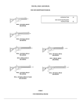
Chapter 1 XLT® Assembly
Assembly
WASHERS
BETWEEN
EACH LOOP
EAR & CLEVIS
LOOP OR SEARCH
COIL
Twist and insert each end of
handle (provided) through top
of shipping carton into
second flap.
(CARRY CARTON)
CABLE RETAINERS
DISPLAY
1/ PRESET PROGRAMS
2/ BASIC ADJUSTMENTS
3/ PRO OPTIONS
4/ TARGET ID NUMBERS
5/ TARGET ID ICONS
6/ TARGET ID SIGNAGRAPH®
7/ BATTERY STRENGTH
CENTER ROD
SECTION
CLEVIS
LOWER
ROD
LOOP
CABLE
CAMLOCKS
TOUCH PADS
SELECT PROGRAMS
ADJUST CONTROLS
“S” ROD
ELBOW
CUP
STRAP
Trigger behind display activates
depth reading and
pinpoint mode.
LOOP CONNECTOR
ELBOW CUP
FOAM PADS
INSIDE ELBOW
CUP
Remove decal paper from the two rubber
bumpers. Install on the bottom of the control
box, one in each of the front corners (shown
below by "X"). Press in place and hold firmly
for a few seconds then release.
"X"
"HOT KEY" SHORTCUTS
"X"
COIN PROGRAM
SQUEEZE & RELEASE TRIGGER
AFTER BATT. CHECK.
SCROLL OPTIONS
ATER BATT. CHECK USE
TO SCROLL CURRENT SETTINGS
OR MAKE ADJUSTMENTS
REVERSE DISPLAY
WHILE SEARCHING. HOLD
THE TRIGGER AND PRESS
AIR/GND BALANCE
IN SEARCH MODE PRESS
TO RE-AIR/GND BALANCE
BACKLIGHT
IN SEARCH MODE, HOLD THE
TRIGGER AND PRESS
RELEASE TRIGGER
PUSH
GROUND BALANCE ONLY
WHILE SEARCHING HOLD THE
TRIGGER AND PRESS
VIEW ANGLE
WHILE SEARCHING HOLD
THE TRIGGER AND PRESS
RELEASE TRIGGER
PUSH
BATTERY CHECK
WHILE SEARCHING, HOLD THE
TRIGGER AND PRESS
PRESS
FOR
LIGHT/DARK BACKGROUND.
RELEASE TRIGGER
CONTROL BOX
2
HEADPHONE
JACK
BOTTOM OF
CONTROL BOX
BATTERY
COMPARTMENT
DOOR
BATTERY
COMPARTMENT
LATCHES
Chapter 1 XLT® Assembly
Assembly Instructions
1. Remove all parts from shipping carton and
check the assembly page to make sure all parts are
present.
readjust clevis/lower rod length with the sping clip
buttons so that the search coil can be held near the
floor without requiring stooping over.
2. There are rubber washers between clevis/lower
rod and loop ears. Use only nonmetallic washers,
fiber bolt, and thumbnut to secure loop/search
coil to clevis/lower rod.
7. Remove the protective paper from the two black
elbow cup foam pads. Carefully align pads on the
inside of the elbow cup, one on each side of the
center rod, and press firmly into place.
3. Unlock "S" rod camlock and insert clevis/
lower rod into curved "S" rod so that stainless
steel spring clip buttons line up and lock into one
of the adjustment holes in the curved "S" rod.
Turn camlock to secure. The second or third
adjustment holes are suitable for average size
adults. Individuals 6' or taller should use the fully
extended position. Individuals well over 6' tall
should purchase the optional Tall Man Rod.
8. Adjust the elbow cup strap so that it is loose
enough for you to slide your arm in and out without loosening each time you want to set the detector down. The elbow cup strap provides extra
leverage and control. However, some prefer not to
use it.
4. Unravel loop cable and wind the cable around
the clevis and rod assembly, first revolution over
the top of the rod. Wind cable all the way to the
top of the curved "S" rod, about five revolutions.
Use the black cable retainers, one near the loop,
and one near the top of the curved "S" rod, to hold
the loop cable in place.
5. Unlock control box rod camlock and insert
curved "S" rod so that stainless steel spring clip
buttons line up and lock into the rod on top of the
control box. The "S" rod is designed to curve up
toward the display. However, those who prefer to
sweep the loop close to their feet may desire to
assemble the "S" rod to curve down toward the
ground. Turn camlock to secure. Plug loop connector into control box, screw lock ring to secure.
9. Install battery as described in the next section,
decal facing down, with plastic tab and steel contacts
facing toward inside of battery compartment.
10. It should be noted at this point that the detector
may not work as expected indoors due to the high
degree of metals used in modern construction. It is
best to tune and practice out-of-doors to ensure
stable, predictable results. Additionally, freshlyburied targets will not produce the normal depth
and discrimination results of targets that have been
naturally lost and settled in the ground. Due to the
abnormality caused by digging a hole in the ground
matrix, and the sophistication of the ground rejection circuitry, it may take a number of years for
freshly-buried targets to respond at true depths and
discrimination accuracy. The best way to determine true detection depth is in real search conditions.
6. Grip the instrument by the handle, with your arm in
the elbow cup with strap secure, and sweep the loop/
search coil over the floor. If the instrument fit feels
uncomfortable, adjust the elbow cup by removing
and repositioning the bolt/thumbnut and installing
in one of the optional positions. If necessary,
3
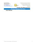
Chapter 2 XLT® Batteries
Batteries
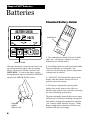
Standard Battery Holder
BATTERY CHECK
VOLTS
BLUE DECAL
Ba
tter
6 LOW
NICAD
OK
CA
yH
ALK
UT
old
ION
er #
802
-71
14.0
50
LIF
TT
AB
AN
DP
UL
ARROW DOWN
When the instrument is turned on the battery voltage will momentarily appear after the opening
display. The detector will then continue to the
MAIN MENU. To recheck the battery voltage
during operation, squeeze and hold the TRIGGER
and press the ARROW DOWN control.
L
1. The standard battery holder (blue decal) holds
eight “AA” cell batteries. Alkalines are recommended for use with this model.
2. Non-alkaline batteries can be used in this holder.
When non-alkalines or rechargeable “AA”
cells are used, detecting time (before replacement/
recharge) may be reduced.
3. "LOW BAT" will automatically appear on the
display when the batteries become too low to
properly operate the detector.
4. The battery compartment opens by gently
pulling down on the front of each of the two
latches (on the bottom of the control box) releasing
the catch and hinging open the door.
TRIGGER
UNDER
DISPLAY POD
4
The non-rechargeable battery holder can use many
different types of batteries, including rechargeable.
This holder is designed for standard size penlight
"AA" batteries which should be 50 mm ± .10mm.
Battery lengths shorter than this will likely cause
problems with this power supply.
Chapter 2 XLT® Batteries
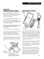
Using the
Standard Battery Holder
1. Slide open the battery holder lid (decal side of
battery holder) by applying gentle upward
pressure on the tab of the door so that it unlocks.
Slide the door away from the battery box
exposing the cell positions.
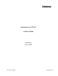
Rechargeable Battery
GREEN
DECAL
BATTERY
CHARGER
Ba
2. Remove any old cells from the holder. Note the
(+) and (-) positions of each cell and the (+)
and (-) for each position marked inside the cell tray.
Install new “AA” cells noting carefully the correct (+) and (-) positions.
If the cells are installed incorrectly, the detector
may require service by an Authorized
Service Center.
CHARGER PLUG
CA
U
T
y # ION
802
-52
11
tter
QUICK
CHARGE
OR OVERNIGHT
SWITCH
3. Slide the door closed so that it snaps securely.
4. Insert the battery holder into the detector so that
the decal is facing down, with the battery
holder door tab and metal contact points facing
toward the inside of the battery compartment.
Close the battery compartment door and secure the
two latches on the bottom of the case. Hook the
front of each latch first, then press down on the
rear.
A rechargeable battery (green decal) is provided
with your instrument. This battery can be recharged
hundreds of times as long as the battery hasn't been
stored for extended periods of time or overcharged.
Full charge can be achieved anytime during the
discharge cycle. When using the QUICK charger
setting use the Charging Hours chart on the following page for charge time. A full charge will last ten
to fifteen hours of normal use.
Battery life will vary with temperature, the number
of targets found, and the exact settings used. Six
hours is not unusual for extreme high performance
settings, backlight use, or for batteries that have
experienced extensive use.
BATTERY
COMPARTMENT DOOR
BATTERY HOLDER
WITH DECAL SIDE DOWN AND
METAL CONTACTS TO FRONT
Your charger has a switch on it that selects the
QUICK charge, or OVERNIGHT charger options.
Always check the position of this switch prior to
charging. Always follow the charge hours on the
chart on the following page when the QUICK
charge setting is used. Over-charging with the
QUICK charge setting will damage the system.
5
Chapter 2 XLT® Batteries
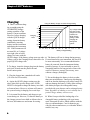
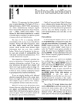
Charging
Using the Battery Charger on Quick Charge Setting
1. There is no harm charg5
ing overnight using the
4.5
OVERNIGHT charger
Any voltage reading
4
less than 8 voltssetting regardless of the
3.5
charge for 5 hours
battery's current condition.
3
maximum on
Charging
However, before charging
Quick Charge
2.5
Hours
with the QUICK charger
setting. Further
2
charging can
setting, determine battery
1.5
damage the
condition by inserting
1
system.
battery into the instrument
0.5
0
and turning the instrument
13 12 11.5 11 10.5 10 9.5 9 8.5 8
7.5 7 6.5
6
ON. If the instrument will
Battery
Voltage
Reading
not turn ON, or if voltage
tests eight volts or below,
charge five hours with the
QUICK charge. If the battery voltage tests any other 6. The battery will lose its charge during storage.
voltage, refer to the Charging Hours chart above for If stored inserted in your instrument, this loss will
be more noteworthy. It is recommended that the
proper QUICK charge time.
battery be removed from the instrument during
2. To charge, insert the charger plug into the battery periods of storage. It is not advisable to store rechargeable batteries for long periods of time withpack jack, located near the plastic tab and
out use. If however, storage is necessary, store
metal contact points.
without a charge (discharged).
3. Plug the charger into a standard wall outlet.
7. Do not discharge the battery in devices other
(110 volts for USA models).
than your metal detector. Unnecessary discharging
and/or an absolute discharge will reduce battery life
4. Again, the QUICK charger setting uses the
and may damage the battery. Unlike older rechargeabove chart for a specific charge time. OVERNIGHT is designed to charge the battery in as little able battery designs, the rechargeable battery
provided with your detector can be recharged at any
as fourteen hours. However, no harm will come to
time. Regardless of whether or not it already has a
the system leaving it charging for several days.
partial charge, memory will not occur.
5. It is normal for the battery and charger to get
8. White's has provided the leading edge of rewarm during use. However, if either the battery or
chargeable battery technology with your instruthe charger gets too hot to hold or deforms due to
ment. Disregard all advice which conflicts with the
the heat, discontinue use and return for testing.
above recommendations. Care for batteries provided by other manufacturers, or with other White's
models, may vary.
6
Chapter 2 XLT® Batteries
Battery Life & Memory
Volatile memory temporarily holds any program
changes or settings not yet saved in a Custom
Program. Short-term or volatile memory is retained
so long as a good battery remains in the detector.
To recover volatile memory immediately squeeze
and release the TRIGGER once the detector is
turned ON. If the battery is removed all volatile
memory is lost. Long-term memory (programs
saved in Custom Programs) is automatically saved
for up to ten years regardless of whether a battery is
in the detector or not.
Use of maximum backlight may reduce battery life
by up to 50%, depending on battery type.
Rechargeable batteries gradually deteriorate. As
they age they do not provide the life-per-charge
they did when new. This is expected, and not
grounds for replacement under warranty. Additionally, a damaged initial cell, which is caused by
over-charging with the QUICK option, is not
replaced under warranty. Only cell failure through
normal use, or a defect due to a problem with a
White's warranted XLT® charger, is covered.
When using fresh batteries, the voltage will initially
check somewhere in the 10 to 14 volt area. Unlike
standard batteries, the rechargeable battery voltage
will quickly drop to between 9 and 10 volts and
plateau there for most of its life. Once the rechargeable battery voltage drops below this plateau, it will
quickly drop below a usable voltage level (eight
volts) and thus require a recharge. Low Battery will
automatically appear on the display when the
battery reaches eight volts.
Like a personal computer, there are times (such as
low battery conditions) when the microprocessor of
a metal detector becomes out of sequence with the
rest of the circuitry. This is often noted by peculiarities in the non-discrimination or pinpointing
(TRIGGER squeezed) modes. Symptoms may be
blaring or silent non-discriminate or pinpoint
modes, depth indication inaccuracies or general
abnormal operation. To correct such difficulties "reboot" by:
1. Install a good battery.
2. Turn ON wait for MAIN MENU to appear.
3. Open battery door and remove battery while
detector is still ON.
4. Wait one minute, re-install battery, turn
detector ON, and check for proper function.
7
Chapter 3 XLT® Quick Start
®
XLT Quick Start
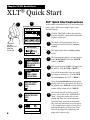
XLT® Quick Start Instructions
2
1
After you have assembled the XLT® and inserted the
battery pack, follow these simple steps to start
treasure hunting!
SOFTWARE
VERSION #
TRIGGER
UNDER
DISPLAY POD
CENTER
POSITION
1
With the TRIGGER in the center position,
press the ON/OFF control and an automatic
sequence will begin.
2
The display will momentarily show an
opening screen which lists the software
version.
3
The display then shows a battery check
screen.
4
The last automatic display screen to appear
is the MAIN MENU. Press the ENTER
control. ("BEEP")
5
The Preset Program COINS will appear on
the MENU. Press ENTER . ("BEEP")
6
You will be prompted to raise the search
coil (loop) to waist level. Press ENTER .
This air balances the XLT®. ("BEEP")
BATTERY CHECK
3
VOLTS
6 LOW
4
ALK
NICAD
OK
14.0
MAIN MENU PG. 1/1
PRESET PROGRAMS
BASIC ADJUSTMENTS
PRO OPTIONS
(press ENTER)
5
PROGRAMS
PG. 1/3
COINS
COIN & JEWELRY
JEWELRY/BEACH
(press ENTER)
6
RAISE LOOP TO WAIST
LEVEL THEN PRESS
ENTER
7
Next, the ground balance prompt appears
asking you to lower the search coil (loop) to
the ground. Press ENTER. Ground mineralization will be balanced out. ("BEEP")
(press ENTER)
7
LOWER LOOP TO GROUND
SURFACE THEN PRESS
ENTER
(press ENTER)
8
+88
-95
8
25¢
0
(LIVE SEARCH SCREEN)
+95
8
The last screen will be the live search
screen. You will hear the THRESHOLD
"hum". Sweep the search coil over the
ground and listen for a solid repeatable/
consistent beep, then look at the display.
The icons tells what likely coin lies below.
V.D.I. number/chart on top of control box
and SignaGraph® provide greater detail.
Squeeze the trigger for pinpointing and
depth and it's time to dig!
Chapter 3 XLT® Quick Start
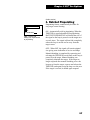
Search Fundamentals
The loop/search coil must be in motion (sweeping from side-to-side) for this instrument to
respond to metal. Practice a smooth sweep of the
loop from side-to-side keeping the loop close to the
ground throughout the swing. Each pass of the
loop should take approximately two seconds
from right to left, two seconds to return from left
to right.
Walk forward slowly. Take small steps no greater
than half normal strides. Make sure each pass of the
loop overlaps the last by at least half the length of
the loop. Do not lift the loop at the end of each
swing. Keep it close to the ground at all times.
To become comfortable with sweeping the loop
takes some practice. Try to loosen up and find a
comfortable grip on the handle. Premature fatigue
may result from gripping the handle too tightly,
improperly adjusted rod or elbow support, and
limited body movement. Hold the handle loosely.
Adjust the rod and elbow support for comfort and
keep the elbow strap loose. Use your arm, shoulder
and even your back a little to allow a smooth even
sweep of the loop.
Now that you're sweeping the loop smoothly over the
ground, you will notice that the detector starts making
sounds (beeps). Not all sounds are good targets;
some trash targets also make the detector beep.
As the loop is swept over the ground, ignore the
display and concentrate on the sounds the detector
makes.
As the loop is passed over metal that is likely trash,
the sound will be inconsistent. Trash targets typically produce a shorter, sputter-type sound, that is
often broken or double in nature. Place a steel-pop
bottlecap on the ground. Pass the loop over it
several times to become familiar with this sound at
different loop sweep speeds. Note that an aluminum
twist-off bottlecap cannot be used as it is a different type of target. Also note that very old rusty
bottle caps may start reading as quarters due to the
elimination of the iron alloy through deterioration.
Once familiar with the sound typical bottle caps
produce, an operator may pass over such targets and
continue searching without consulting the display
information, saving more time for evaluating
possible good targets.
As the loop passes over metal that is likely a good
target, a more consistent and smooth sound will be
heard. A good target typically produces a longer,
more solid sound. Place a quarter on the ground and
sweep the loop over it several times to become
familiar with the sound of a good target.
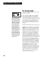
Why Air/Ground Balance?
When the display prompts you to, AIR BALANCE by
holding the loop at waist level and press ENTER. The
XLT®'s circuits are being prepared for ground balancing by measuring temperature and other variables that
affect electronic circuits. The XLT® "beeps" and you
lower the search coil to the distance above the ground
that you will be searching. Press ENTER to have the
XLT® "cancel/track out" or GROUND BALANCE
the ground mineralization. The XLT® then automatically "tracks out" the varying mineralization as you
continue to search.
9
Chapter 3 XLT® Quick Start
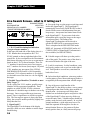
Live Search Screen - what is it telling me?
VISUAL
POSSIBLE TARGET
DISCRIMINATION
IDENTITIES
INDICATION-V.D.I. NUMBER
("ICONS")
("TARGET REFERENCE NUMBER")
+48
-95
SIGNAGRAPH
BARGRAPH
0
+95
1. V.D.I. Visual Discrimination Indication
("target reference number")
In the upper left hand-side of the display there is a
V.D.I. number that corresponds to the V.D.I.
SCALE painted on the top right-hand side of the
control box. It also corresponds to the Discriminate
Edit feature allowing you to reject or accept targets
based on their V.D.I. reference number. There are
"+" numbers for non-ferrous (not of iron) targets,
and "-" numbers for ferrous (iron) targets. Rejected
V.D.I. numbers may not appear if the VISUAL
DISCRIMINATION feature is ON. Reasonably
consistent V.D.I. reference numbers (± five digits),
in a desirable area of the chart is a vote for digging
the target.
2. Possible Target Identities ("Probable or most
likely Target")
To the right of the V.D.I. number, possible target
identities will be represented graphically. These
graphics are called ICONS. A fairly consistent
indication of a desirable target is another vote to dig
the target. One or two possible target icons may
appear. There is significance to which icon appears
first. The first target to appear is always the most
likely, the second is another possibility slightly less
likely than the first.
3. SignaGraph™
The SignaGraph™ at the bottom of the display
provides a final vote as to whether or not the target
should be dug.
10
A. Sweep the loop over the target several times and
look at the SignaGraph™. The SignaGraph™
automatically clears itself (FADE RATE) so that it
doesn't fill the screen with information from past
loop sweeps. An operator has limited time to look
at the SignaGraph™. If you want to look at the
information again, sweep the loop over the target
several more times. The fading of the
SignaGraph™ information can be slowed or
speeded (FADE RATE) to operator preference.
This is completed in the PRO OPTIONS under
DISPLAY. Automatic AVERAGING and/or ACCUMULATING of SignaGraph™ information is
also available (See PRO OPTIONS).
B. Valuable targets will show up on the positive
side of the graph. The positive area of the chart is
the section located to the right of the zero.
C. Look for consistency. In ideal conditions, coins
and jewelry produce one or two bars to the right of
zero. Trash produces several bars, sometimes on
both sides of zero.
D. In less than ideal conditions, coins may produce
a wider pattern of bars. Most trash targets produce a
recognizably different pattern than valuable targets.
E. One of the most visual benefits of the
SignaGraph™ is the ability to show a smear pattern
on iron targets that often fool the other methods of
identification. An iron target will likely show
definite bars on both the negative and positive sides
of the SignaGraph™, often smearing all the way
across the entire chart. Valuable targets should not
produce such obviously wide patterns. In very bad
ground conditions, a good target may have a few
small bar segments in the negative area due to
mineralization. However, the pattern will show
mostly positive bars, in a fairly narrow tall group.
Chapter 3 XLT® Quick Start
Live Search Screen Samples
+19
-95
5¢
0
+88
-95
+95
Quarter. Could
be a worn half,
or large silver
jewelry.
25¢
0
Nickle, or
possible ring.
Sometimes a
small (or half)
pull tab will
produce this
indication
+95
0
IRON. -18
ACCEPTED or
VISUAL DISC.
OFF.
-95
0
Pull tab.
Possible ring.
+30 ACCEPTED or
VISUAL DISC.
OFF.
+30
-95
0
+95
0
10¢
+95
Dollar. Large
non-iron can
also produce
this indication
(large brass jar
lids).
1$
0
+95
IRON. +95
ACCEPTED or
VISUAL DISC.
OFF
+95
0
+10
-95
+95
1¢
+93
-95
+95
-18
-95
-95
IRON. REJECT
targets will
produce only a
SpectraGraph™
if VISUAL
DISC. is ON
-95
+80
+95
Foil. Possible
ring. +10
ACCEPTED or
VISUAL DISC.
OFF.
FOIL
0
+95
Ring. Possible
pull tab. +48
ACCEPTED or
VISUAL DISC.
OFF.
+48
-95
Penny or a
dime. If the
screw cap and
penny ICON
are displayed,
the target can
be an Indian
Head or zinc
penny.
0
+95
11
Chapter 3 XLT® Quick Start
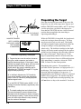
Pinpointing the Target
"X" THE LOOP TO "PINPOINT"
THE TARGET
SQUEEZE TRIGGER
DEPTH SCREEN
DISPLAYED WHEN
THE TRIGGER
IS SQUEEZED
10.5"
+ - 1 2 - + - + - 9 - + - + - 6 - + - + - 3 - + - + - 0
Advanced Pinpointing Techniques
1. Targets that are near the surface, because
they give a wider response, are harder to
pinpoint than deep targets. If the trigger is held
and the loop swept over the area, you may note
a shallow depth indication. Lifting the loop
slightly above the ground, releasing and resqueezing the TRIGGER and again "X" ing the
target will aid pinpointing.
2. In the Basic Adjustments, DC Sensitivity
(non-motion) directly controls the pinpointing
mode. Lower DC Sensitivity settings pinpoint
shallow targets better.
3. In the PRO OPTIONS under AUDIO, V.C.O.
(Voltage Controlled Oscillator) significantly aids
pinpointing.
4. The depth reading has two indication bars.
The top bar shows the current distance from
the target, and the bottom bar shows a memory
of the strongest reading. These two bars will be
even with each other when the loop is directly
over the center of the target.
12
Once the decision has been made to dig, move the
loop off to one side of the target area, squeeze and
hold the TRIGGER on the handle, and "X" the loop
over the spot where you believe the target to be.
Note that the TRIGGER also has a locked forward
position that accomplishes the same thing as
squeezing and holding it.
While the TRIGGER is being held, the loop doesn't
need to be moving to detect the target. The loop
may be moved slowly over the area. The display
will indicate depth in inches and will also show the
strongest reading to aid in pinpointing exactly
where to dig. The shallowest reading on the depth
display, the loudest sound coming from the speaker,
and the two bars lining up with each other, indicate
the center of the target. Don't forget to "X" the
target as pinpointing cannot be accurate unless the
target is swept from at least two different directions.
Once pinpointing is complete, release the TRIGGER, or return it to the center position.
Pinpointing takes practice. The standard loop
provided with the Spectrum® is a high-powered, 9.5
inch design. This loop's strongest traits are in the
detection depth and ground coverage areas. If
pinpointing becomes difficult or critical, an optional
smaller loop is suggested. The smaller loops have
advantages in high trash areas and pinpointing, but
will not detect as deep as the standard 9.5 inch size.
Chapter 3 XLT® Quick Start
Ready to Dig
Factory Preset Programs
Permission - Prior to searching and digging you
must have permission to search private property,
from the owner or caretaker.
Reached from the MAIN MENU, the factory
PRESET PROGRAMS give a quick start for:
Laws - Know the laws that apply to the area you
are going to search. Laws vary a great deal with the
City, County, State, and Country, regarding the use
of metal detectors. Be respectful of private property, public property, and the laws which govern
the use of metal detectors.
Tools - Care must be taken to dig in a way that is
friendly to the landscape. Tools and methods vary a
great deal with the area, season, and types of target
you are recovering. Check with your dealer for
recommended tools and methods for your area.
Trash - When searching, remove all trash you
come across. This not only makes your future
searches of the area more productive; it promotes
the hobby of metal detecting.
Get Involved - Your dealer knows of metal detecting clubs and organizations which promote and
protect the hobby. A club is a great way to not only
learn good detecting habits, but to gain permission
to search areas as a group as well as have organized
competition hunts.
Coins: general purpose settings, discriminates
(rejects) most common junk items like nails, foil,
pull tabs, and hot rocks; and responds to most coins
and large jewelry. Use in lawns, parks, and playgrounds where lots of trash rejection is desired.
Coin & Jewelry: less discrimination (less trash
rejection), desirable because of the high degree of
variance found in jewelry alloys. More digging
required. Good program for lawns, parks, and
playgrounds. Use screen more than sound.
Jewelry & Beach: similar to Coin & Jewelry, but
Pro Options are changed for salt water.
Relic: even less discrimination than Coin & Jewelry
or Jewelry & Beach, all types of metals except
small iron items like nails, and some stainless steel.
Brass, lead, aluminum, as well as copper, silver,
and gold all respond solidly. Ferrous (iron), such as
large nails, weapons, and cannon ball fragments
will also respond . Suitable for all significant targets
and separate ferrous/non-ferrous by display indications.
Prospecting: NO AUDIO DISCRIMINATION. All
metals respond with beep. But V.D.I. numbers
show only for metals that could be gold. Dig only
V.D.I. number (possibility gold) targets and avoid
iron. Targets which cause an audio response, without causing a V.D.I. number to appear on the
display, are not likely to be gold nuggets. Although
high-frequency gold-shooting detectors will respond better, this mode will offer good results for
the occasional nugget hunter by responding to
nuggets in the nine-grain and heavier category.
13
Chapter 4 XLT® Basic Adjustments
Basic Adjustments
Basic Adjustments - what do they do?
1. TARGET VOLUME - How loud a target beeps when detected.
2. AUDIO THRESHOLD - The slight hum or background sound heard continuously during searching.
3. TONE (AUDIO FREQUENCY) - Selects the frequency or pitch of sound the detector produces.
4. AUDIO DISCRIMINATION - The ability to reject trash, different sounds for different types of targets.
5. SILENT SEARCH - The ability to operate without the threshold or background hum.
6. MIXED-MODE - DC non-discriminate mode, working simultaneously with AC discrimination mode.
7. A.C. SENSITIVITY - Degree instrument is responsive to signals in the discriminate (motion) modes.
8. D.C. SENSITIVITY - Degree instrument is responsive to signals in non-discriminate (non-motion) modes.
9. BACKLIGHT - Used in dark conditions to light the display improving visibility.
10. VIEWING ANGLE - Adjusts the display for low or high temperature visibility.
Basics of Basic Adjustment
MAIN MENU PG. 1/1
PRESET PROGRAMS
BASIC ADJUSTMENTS
PRO OPTIONS
(press ENTER)
ADJUSTMENT
EXAMPLE:
TARGET VOLUME
56
MIN
MAX
(press ENTER)
RECTANGLE AROUND
THE TITLE MOVES TO
THE SETTING
USE ARROW KEYS TO
ADJUST THE SETTING
UP OR DOWN
TARGET VOLUME
56
MIN
MAX
TIP - To quickly increase to
maximum, hold ENTER and
press ARROW up. To quickly
decrease to minimum, hold
the ENTER and press
ARROW down.
ADJUSTMENT
EXAMPLE:
SILENT SEARCH
ON
OFF
TO CHANGE PRESS ENTER
14
After you have had some field experience, you may
want to make some changes to the basic settings of
your detector. From the search mode press
MENU. At this point, the MAIN MENU will
appear on the display. Use the ARROW controls to
move the pointer to Basic Adjustments, and then
press ENTER. You may now use the ARROW
down control to scroll through the Basic Adjustments.
Using the first adjustment screen (TARGET VOLUME) as an example, the screens with a graphic
control knob require you to first press ENTER
then use the ARROW up and down controls to
adjust. Note when ENTER is pressed the square
around the title moves to the setting, indicating you
are ready to make adjustments with the ARROW
controls. After adjusting press MENU and use the
ARROW controls to continue viewing / setting
other Basic Adjustments, or squeeze and release the
TRIGGER to begin searching
Adjustment screens with an on/off selection need
only for you to press ENTER to change setting.
Pressing ENTER again changes back to the original
setting.
Chapter 4 XLT® Basic Adjustments
More Basics
"Hot Key" Shortcuts
All the MENU items are tied together so that the
ARROW up and down controls scroll through every
adjustment screen. If you continue to press the
ARROW down you can go beyond the last BASIC
ADJUSTMENT (View Angle) and into the PRO
OPTIONS. If the ARROW up control is pressed
after VOLUME, you will be scrolling backwards
through the options starting with the end of the
Preset Programs, then the MAIN MENU, then the
end of the PRO OPTIONS.
"HOT KEYS" will save time as they allow easy
access, from the search mode, to the most needed
adjustments. They are painted on the bottom of the
control box for field reference.
An important feature of the ARROW controls; If a
BASIC ADJUSTMENT has been made (for example Volume) and the trigger has been squeezed
and released to return to a search mode, you can
return to the volume adjustment simply by pressing
either of the ARROW controls. This shortcut
returns to the last adjustment that was made thereby
allowing an operator to switch directly from a
search mode to the adjustment currently being fine
tuned. This feature is desirable as you start using
BASIC ADJUSTMENTS or PRO OPTIONS that
are located further down the menu listings, or any
adjustment that may require some trial and error to
find the appropriate setting.
AIR/GROUND BALANCE - In search mode,
press ENTER to re-Air/Ground Balance.
If care is taken to use a desired adjustment screen
last (just prior to squeezing and releasing the TRIGGER for a search mode), Custom Programs (such as
a competition hunt program) can use this ARROW
RETURN feature to allow quick easy access to the
most used feature (Transmit Frequency). Use that
feature (adjustment screen) last, just prior to
squeezing and releasing the TRIGGER for searching. Then during searching, press either ARROW to
return directly to that adjustment screen.
COIN PROGRAM - Squeeze & release TRIGGER
after automatic battery check.
SCROLL OPTION - After battery check, use
ARROWS to scroll all the current settings / menus.
GROUND BALANCE ONLY - While searching,
hold the TRIGGER and press ENTER.
BATTERY CHECK - While searching, hold the
TRIGGER and press ARROW down. Sqeeze and
release TRIGGER to return to searching.
REVERSE DISPLAY - While searching, hold the
TRIGGER and press ARROW DOWN. Press
ARROWs for light/dark background. Light or dark
background will not change battery life. It will
make the display easier for some to read, particularly in certain light conditions. It will work in
combination with backlight. Reversed display is
only accessible through the "HOT KEYS".
BACKLIGHT - In search mode, hold TRIGGER
and press MENU. Release TRIGGER, press
ARROWS to set.
VIEW ANGLE - While searching, hold the TRIGGER and press ARROW up. Release TRIGGER,
press ARROWS to set.
15
Chapter 4 XLT® Basic Adjustments
Custom Programs - Saving
your Basic and Pro Option
adjustments for future use.
Save custom settings in any one of four custom
program positions. They will remain permanently in
the XLT® memory regardless if the machine is
turned off or the battery removed. Custom Programs can be changed at any time by saving new
settings over a previously saved custom program.
4
PROGRAMS PG. 2/3
RELIC
PROSPECTING
TRASH
USE THE ARROW KEYS TO SCROLL THE
FLASHING SYMBOLS, PRESS ENTER
PROGRAMS PG. 2/3
RELIC
PROSPECTING
TRASHY PARKS
PRESS MENU
1
SQUEEZE
TRIGGER
2
THEN PUSH
MENU
MAIN MENU PG. 1/1
PRESET PROGRAMS
BASIC ADJUSTMENTS
PRO OPTIONS
PRESS ENTER FOR PRESET PROGRAMS
PROGRAMS
PG. 1/3
COINS
COIN & JEWELRY
JEWELRY/BEACH
SCROLL DOWN WITH ARROW KEYS
PRESS ENTER
16
2 Use the ARROW controls to select one of the
2.
four Custom Programs then press ENTER.
3 You now must make one of three choices (use
3.
the ARROW controls to make your selection):
A. LOAD will activate a prior custom program stored in that position. After you have
SAVED or NAMED a program, you can
select LOAD and press ENTER, to use that
program.
PROGRAMS PG. 2/3
RELIC
PROSPECTING
CUSTOM PROGRAM 1
B. SAVE saves your current settings in that
custom position with either a generic name or
a prior custom name you may have applied.
Selecting SAVE and pressing ENTER saves
the current program.
C.P. OPTIONS PG. 1/1
LOAD
SAVE
NAME
C. NAME is the preferred method. Select
NAME and press ENTER. You may now use
the ARROW and ENTER controls to name
your custom program. NAME automatically
SAVES, once you have chosen a name and
pressed MENU.
PRESS ENTER
3
1 Once all of the changes you desire have been
1.
made to any Preset Program or existing Custom
Program, squeeze and release the TRIGGER as if to
search.Then push MENU for MAIN MENU.
Chapter 4 XLT® Basic Adjustments
44. To NAME, use the ARROW controls to select the
first symbol, number, or letter of the name and press
ENTER. Use the ARROW controls to select the
second symbol, number, or letter of the name, press
ENTER. And so on using up to sixteen digits. To
leave a space, use the ARROWS to select the point
where no symbol or letter appears and press ENTER.
If you make a mistake and press ENTER when the
digit is not as you desire, simply keep pressing ENTER until that digit is again flashing, then use the
ARROWs to select the correct digit and again press
ENTER. It is wise to name the custom program
something that relates to what it is used for. For
example "TRASHY PARKS", "SMALL LOOP",
"GHOST TOWN", "NIGHT HUNT", "COMPETITION", etc. Once the name is fully assembled press
MENU.
5. Once you have SAVED and pressed ENTER, or
NAMED and pressed MENU, there are four directions
you can go:
A. Squeeze and release the TRIGGER to continue searching using your new custom program.
B. Press ENTER, select LOAD and press
ENTER to continue searching using your new
custom program.
C. Press MENU to return to choose or develop a
different program than what you stored.
D. Turn the detector OFF.
6. When the detector is turned back on, regardless of
whether a battery pack was left in the detector or
not, your custom program will be ready for you to use
again and again. Simply select it, press ENTER, select
LOAD, and press ENTER again. Follow the onscreen instructions for Air/Ground Balance and then
search.
new program using the same procedure as described above. The old program can only be erased
when a new program is stored in that position.
8. You can NAME a custom program and at a later
date replace the program while maintaining the
same name. Develop the changes first to any program, then use the SAVE method which maintains
the old name while storing the new program. To
keep the same program with a new name, first
LOAD that custom program, Air/Ground Balance,
then press MENU and go to that custom position
and press ENTER. Now select NAME and press
ENTER. You can now develop a new name for the
old program.
Other Custom Program info
Ground Balance - When a Custom Program is
stored, the Ground Balance setting last used with
that program is also stored. This has advantages
particularly for those who manually set the Ground
Balance for speciality applications. The automatic
Air/Ground Balance sequence will always override
manual settings. To access the last Ground Balance
setting used with a Custom Program, first select the
desired Custom Program then press ENTER. Select
LOAD and press ENTER. Do not Air/Ground
Balance as the display suggests, simply squeeze and
release the TRIGGER. The last Ground Balance
setting will then be in use. If an appropriate Air/
Ground setting is not available, the instrument will
automatically require a new Air/Ground Balance.
Return ARROW Key - The last Basic Adjustment
or Pro Option screen used is remembered by your
Custom Program. From the search mode, either
ARROW control will access the last Basic Adjustment or Pro Option screen used. This allows easy
access to the most used adjustment (such as Transmit Frequency) for a custom competition hunt
program.
7. If you SAVE or NAME a program, then decide you
no longer want to keep it, you can replace it with a
17
Chapter 4 XLT® Basic Adjustments
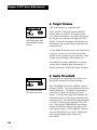
1. Target Volume
TARGET VOLUME
56
MIN
MAX
Tip - Select the loudest
comfortable level, lower
with headphones, higher
without.
How loud a target beeps when detected.
Select TARGET VOLUME with the ARROW
controls and press ENTER. The current volume
level sounds continuously. The number designating
the current level is shown on the right side of the
display. To the left, the graphic knob indicates the
relationship of the current setting to minimum and
maximum levels.
Use the ARROW controls to select the volume level
you desire. Volume level will select the loudest
possible sound a shallow target can produce. High
volume levels will slightly reduce battery life.
Press MENU and use the ARROWS to continue
viewing and or adjusting Basic Adjustments, or
Squeeze and release TRIGGER to begin searching.
2. Audio Threshold
AUDIO THRESHOLD
23
MIN
MAX
Tip - Select the lowest
level you can still hear.
18
The slight hum or background tone which is normally heard continuously during searching.
Select THRESHOLD with the ARROW controls,
and press ENTER . The current threshold level will
sound continuously. The number designating the
current level is shown on the right side of the
display. To the left the graphic knob indicates the
relationship of the current setting to minimum and
maximum levels. Note that the maximum threshold
level (42) is well below the minimum VOLUME
level. Thus with the THRESHOLD at maximum,
and the VOLUME at minimum, the detector will
still respond to metal. Use the ARROW control to
select the threshold level you desire. High threshold levels will slightly reduce battery life.
Press MENU.
Chapter 4 XLT® Basic Adjustments
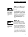
3. Tone (Audio Frequency)
TONE(AUDIO FREQ)
231
MIN
Selects the frequency or pitch of the sound the
detector produces. This is different than Transmit
Frequency which is described in the Pro Options
under Signal .
MAX
Tip - If you have trouble
hearing high frequencies
select low TONE levels
(low numbers). If you have
trouble hearing low frequencies, select high
TONE levels (high numbers).
Select TONE (AUDIO FREQ.) with the ARROW
controls and press ENTER. The current TONE
will sound continuously. The number designating
the current level is shown on the right side of the
display. To the left, the graphic knob indicates the
relationship of the current setting to minimum and
maximum levels. Low frequencies, from about
100 down, begin to pulse. Select an audio frequency that you can hear comfortably and provides the best definition for your ears. Press
MENU.
4. Audio Disc.
AUDIO DISCR.
ON
OFF
TO CHANGE PRESS ENTER
Tip - Use AUDIO DISC
ON for trash rejection,
AUDIO DISC OFF for
detection of all types of
metals.
The ability of the detector to reject trash by
producing different sounds for different types of
targets. Trash is rejected by going silent or
producing a broken "cut-short" sound. Valuables
are detected by a smoother more solid sound.
Select AUDIO DISC. with the ARROW controls,
use the ENTER control to turn AUDIO DISC. ON
or OFF. When ON, specific targets will be accepted
or rejected based on the Program currently in use.
Audio Disc. turns ON or OFF the entire audio
discriminate feature. When OFF, all types of metals
produce an audio tone (beep). Only by selection of
a different Program, or by entering the Pro Options
under Discrimination, can specific target's (V.D.I.
numbers) acceptance or rejection criteria be altered.
Press ENTER.
19
Chapter 4 XLT® Basic Adjustments
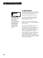
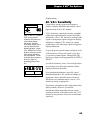
5. Silent Search
SILENT SEARCH
ON
OFF
The ability of the detector to be operated without
the threshold or background hum that is normally
heard continuously during operation. The
instrument is silent until a target is detected.
TO CHANGE PRESS ENTER
Tip - A threshold hum is
recommended as it often
fades over rejected
targets providing
information about targets
and ground conditions. If
the constant noise
bothers or distracts you
and reduced AUDIO
THRESHOLD doesn't
help, select SILENT
SEARCH.
20
Select SILENT SEARCH with the ARROW
controls and use the ENTER control to turn
SILENT SEARCH ON or OFF.
AUDIO DISC. needs to be ON and MIXED
MODE needs to be OFF for SILENT SEARCH to
perform properly.
In Pro Options the Discriminate feature can be
used to accept all metal targets while using
SILENT SEARCH. It is not possible to achieve a
non-motion searching mode with SILENT
SEARCH ON. When SILENT SEARCH is ON
the all metal pinpointing mode continues to
produce a threshold. This may not be noticed, as
once the pinpoint mode detunes for better target
center locating the threshold is not present.
However, releasing, re-squeezing, and holding the
TRIGGER with the loop at waist level a threshold
will be noted. Press ENTER.
Chapter 4 XLT® Basic Adjustments
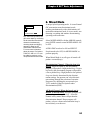
6. Mixed Mode
MIXED MODE
ON
OFF
TO CHANGE PRESS ENTER
Tip - Advanced operators can
gain extra depth by monitoring
the all-metal and discriminate
channels simultaneously,
checking depth and digging
targets too deep for the
discriminate channel alone.
For even more information
about the target, Pro Options
TONE I.D. and or V.C.O. can
be added to produce a truly
unique advanced users mode.
A unique hybrid operating mode. It is an all-metal
(DC non-motion, non-discriminate) mode,
working simultaneously with a discriminate (AC
motion discrimination) mode. It is two modes, one
detecting everything and another discriminating,
operating at the same time.
Select MIXED MODE with the ARROW controls,
press ENTER control to turn MIXED MODE ON
or OFF.
AUDIO DISC needs to be ON and SILENT
Search needs to be OFF, for MIXED MODE to
perform properly.
When Mixed Mode is on, all types of metals will
produce a sound (beep).
Discrimination Channel - When the loop is in
motion, targets accepted by the discriminate
program will produce a high-pitched beep. Targets
rejected by the discriminate program will produce
a lower pitched beep. High-pitched or low-pitched
beeps are directly determined by the discrimination settings. An operator can select discriminate settings through the selection of an entire
Program or by adjusting the accept and reject
V.D.I. numbers in the Pro Options under
Discrimination (EDIT).
All Metal Channel -When the loop is not in
motion, or moved slowly, all types of targets will
produce the same low-pitch beep. All-metal
channel will by nature detect deeper than the
discrimination channel. Deeper targets will
produce a lower volume sound when the loop is
moved slowly over the area.
21
Chapter 4 XLT® Basic Adjustments
7. A.C. Sensitivity
A.C. SENSITIVITY
64
MIN
Used to select the appropriate sensitivity (degree
that the instrument is responsive to signals) while
being used in the discriminate modes (those which
require movement of the loop).
MAX
Tip - Preset levels work
well for most conditions.
Reduced levels will
improve stability in difficult
conditions. Increased
levels will improve
detection depth if stability
can be maintained.
Tip-Remember that once
the TRIGGER is
squeezed and released to
go to a search mode, you
can return to the last
adjustment screen used
by pressing either
ARROW control.
Select A.C. SENSITIVITY with the ARROW
controls, and press ENTER. Use the ARROW
controls to set the level of sensitivity shown by the
number on the right. Press ENTER.
Sensitivity levels adjust detection depth and also
have a direct effect on detector stability. A.C.
SENSITIVITY levels should be selected carefully
to allow stable, predictable performance. Set a
lower level if the detector behaves erratically.
8. D.C. Sensitivity
D.C. SENSITIVITY
30
MIN
MAX
Tip - Typically, lower
D.C. SENSITIVITY
settings pinpoint shallow
targets far better than
high settings. High
settings will however,
produce more pinpointing
(as well as nondiscriminate mode
depth). Pinpointing
(TRIGGER squeezed),
MIXED-MODE, and
V.C.O. AUDIO are
dramatically impacted by
the D.C. SENSITIVITY
setting.
22
Used to select the sensitivity (degree that the detector
is responsive to signals) while the detector is being
used in non-discriminate modes. These are modes that
do not require movement of the loop to respond. D.C.
SENSITIVITY fine tunes stability and pinpointing.
Select D.C. SENSITIVITY with the ARROW
controls, and press ENTER. Use ARROW controls to
select the desired D.C. SENSITIVITY level shown by
the number on the right. Press ENTER. D.C.
SENSITIVITY levels should be selected carefully to
allow smooth, stable and predictable operation while
allowing for reasonable pinpointing.
A.C. and D.C. Sensitivity Adjustments are
traditionally the way to alter detection depth and
stability. There are other methods available in the
PRO OPTIONS under SIGNAL (TRANSMIT,
RECEIVE), PREAMP GAIN.
Chapter 4 XLT® Basic Adjustments
9. Backlight
Used in dark conditions to light the display,
improving visibility.
BACKLIGHT
0
MIN
MAX
Tip - Use only when
needed, and only as bright
as needed, for acceptable
display visibility. Backlight
use will decrease battery
life. The brighter the level,
the higher the battery
usage.
CAUTION
If the instrument is turned ON and the
EMERGENCY BACKLIGHT sequence is
used, the BACKLIGHT will stay ON only
while you stay in that program. Pressing
MENU and selecting another program will
turn BACKLIGHT OFF, if BACKLIGHT
is not also ON in that particular program.
If in the dark at the time the instrument is
turned ON, you may need to squeeze and
release the TRIGGER and then use the
EMERGENCY BACKLIGHT sequence.
You can then find the program you desire,
press ENTER, press ENTER for Air
Balance, and press ENTER for Ground
Balance. Use the EMERGENCY
BACKLIGHT ON sequence a second time
if the BACKLIGHT fades in that program.
Unlike past Spectrum® instruments, the
Spectrum® XLT® BACKLIGHT is no
different than any of the other
adjustments. It can be saved in the custom
programs or short term volatile memory.
However, factory preset programs use the
OFF (0) setting as a default (standard
setting).
Select BACKLIGHT with the ARROW controls
and press ENTER. Use the ARROW controls to
select the desired BACKLIGHT level. The
BACKLIGHT level will be visible on the display.
The current level is shown on the right side of the
display. The graphic control knob shows the
relationship of the current setting to minimum and
maximum levels. Minimum is 0 (no light). The
maximum backlight setting will reduce battery life
by as much as 50% depending on the type of
batteries and how long it is used. Lower
BACKLIGHT settings will have significantly less
drain on battery life.
When the detector is first turned on, it is normal
for the backlight to be on during the opening
display and BATTERY CHECK. If the
BACKLIGHT is off, it will fade when the MAIN
MENU display appears. If the BACKLIGHT is
ON, it will continue until turned off manually or a
different program is selected. BACKLIGHT can
be saved as part of a custom program, for example
a NIGHT HUNT program.
When Backlight is ON and the TRIGGER is
squeezed and released to begin searching,
"BACKLIGHT ON" will appear continually on
the display to warn you of the extra battery duty.
EMERGENCY BACKLIGHT - If in the dark
you cannot see the display to turn the
BACKLIGHT on, holding the TRIGGER and
pressing MENU will bring up the BACKLIGHT
adjustment screen. Release the TRIGGER and
press ARROW up to select a level you can see the
display. Squeeze and release the TRIGGER to
continue.
23
Chapter 4 XLT® Basic Adjustments
10. Viewing Angle
VIEWING ANGLE
25
MIN
MAX
Tip - In cold temperatures
the display typically will
become slower at responding. Settings toward MAX
(higher numbers) speeds
the display and improves
visibility at cool temperatures. In warm temperatures or intense direct
sunlight, the display may
become difficult to see.
Settings toward MIN (lower
numbers) will improve
visibility of the display in all
but extreme situations. If
large variations in conditions result throughout the
day or night's search, you
may have to make several
VIEWING ANGLE adjustments to maintain good
display visibility.
24
Adjusts the display for visibility in low or high
temperature conditions.
Select VIEWING ANGLE with the ARROW
controls and press ENTER, use the ARROW
controls to make changes. The current level is
shown on the right side of the display. The graphic
control knob indicates the relationship of the
current setting to minimum and maximum levels.
Squeeze and release the TRIGGER to resume
searching.
VIEWING ANGLE has no impact on battery life.
EMERGENCY VIEWING ANGLE PROCEDURE- If your detector has been in the cold or
heat prior to use, you may not be able to see the
display to adjust VIEWING ANGLE. Press the
ON/OFF control, hold the TRIGGER and press
ARROW up. You can then use the ARROW
controls to find a VIEWING ANGLE level that
allows you to read the display. Squeeze and
release the TRIGGER to begin searching. Like the
BACKLIGHT, you will lose your custom VIEWING ANGLE setting if you change Programs.
You may need to use the EMERGENCY VIEWING ANGLE PROCEDURE to see the display.
Select the program you desire, use the ENTER
control to enter, Air/Ground Balance, then again
use the EMERGENCY VIEWING ANGLE
PROCEDURE if the display is unreadable.
VIEWING ANGLE is preset at average levels in
the factory preset programs. The display may be
unreadable at either of the extreme settings in a
particular environment. Custom VIEWING
ANGLE settings will be saved when Custom
Programs are stored for future use.
Chapter 5 XLT® Pro Options
Pro Options (Overview)
AUDIO
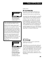
1. RATCHET PINPOINTING - Pinpoint feature, automatically de-tunes for center location.
2. S.A.T. SPEED - Self Adjusting Threshold or Auto-tune, automatically maintains threshold.
3. TONE I.D. - Assigns each V.D.I. target number its own special tone or sound.
4. V.C.O. - Pinpoint or non-discriminate feature, increases pitch or tone with target strength.
5. ABSOLUTE VALUE - Bigfoot or Goldfoot loop accessories only.
6. MODULATION - Motion modes produce the same, or different volume, based on target depth.
G.E.B./TRAC
7. AUTOTRAC - Automatically updates Ground Balance during searching.
8. TRAC VIEW - TRACK appears on right side of display during AUTO TRAC adjustments.
9. AUTOTRAC SPEED - Dictates when AUTO TRAC adjusts Ground Balance.
10. AUTOTRAC OFFSET - Positive or negative AUTO TRAC (over, or under kill).
11. TRAC INHIBIT - Prevents tracking the ground during target detection.
12. COARSE G.E.B. - (Manual Ground Balance) Coarse viewing, or overriding automatic.
13. FINE G.E.B. - (Manual Ground Balance) Fine viewing, or overriding automatic.
DISCRIMINATION
14. DISC. EDIT - Change V.D.I. (target reference numbers) accepted (detected), or rejected status.
15. BLOCK EDIT - Speeds EDIT by dragging ACCEPT or REJECT with ARROW controls.
16. LEARN ACCEPT - Target samples can be used to show or teach ACCEPT discrimination.
17. LEARN REJECT - Target samples can be used to show or teach REJECT discrimination.
18. RECOVERY SPEED - Speeds target responses, so close together targets each respond.
19. BOTTLECAP REJECT - How strongly the instrument rejects or breaks up on iron.
DISPLAY
20. VISUAL DISC. - Rejected V.D.I. numbers and ICONS do not appear on display.
21. ICONS - Graphic display representation of metal targets, ON/OFF.
22. V.D.I. SENSITIVITY - Response intensity to produce a display indication & 3rd V.D.I. digit.
23. D.C. PHASE - Measurement of ground, or metal target, during pinpointing.
24. GRAPH AVERAGING - SignaGraph® information collects over multiples loop passes.
25. GRAPH ACCUMULATING - Emphasizes common or predominate SignaGraph®.
26. FADE RATE - Clears or fades non-current SignaGraph® information (bars).
SIGNAL (TRANSMIT, RECEIVE)
27. TRANSMIT BOOST - Selects the intensity of the signal transmitted from the loop.
28. TRANSMIT FREQUENCY - Alters operating frequency to avoid interference.
29. PREAMP GAIN - Selects the intensity of the signal received from the loop.
25
Chapter 5 XLT® Pro Options
Pro Options
Basics of Pro Options
MAIN MENU Screen
MAIN MENU PG. 1/1
PRESET PROGRAMS
BASIC ADJUSTMENTS
PRO OPTIONS
Pro Options
Sub Menu #1
Pro Options
Sub Menu #2
PRO OPTIONS PG. 1/2
AUDIO
G.E.B./ TRAC
DISCRIMINATION
PRO OPTIONS PG. 2/2
DISPLAY
SIGNAL (TRANSMIT,
RECEIVE)
CAUTION
Be aware that changes you make to a
Program are only in effect as long as you
continue using that Program. If the
detector is turned OFF, the Trigger must
be squeezed and released to recover short
term (volatile) memory upon turning the
detector ON. If you want to keep the
changes you made to a specific program
over an extended time period (days or
weeks), or through battery changes, the
entire Program must be saved in a Custom
Program position.
26
The PRO OPTIONS are used to make the more
intricate adjustments available on this model. The
PRO OPTIONS are divided into five major categories of menus, structured similar to the Basic
Adjustments. Methods of entry, adjustment, exit,
and re-entry remain the same.
To enter the PRO OPTIONS from a search mode,
press MENU and the MAIN MENU will appear.
Use the ARROW controls to select PRO OPTIONS
and press ENTER. The PRO OPTIONS menu will
appear on the display. There are two pages to the
PRO OPTIONS menu (PG. 1/2 Page one of two).
The ARROW controls are then used to select the
desired PRO OPTION category.
The five major categories have options specific to
their titles. For example, all the options under
AUDIO have to do with the way the audio circuits
of the instrument behave. Once a category has been
selected and the ENTER control pressed, the
ARROW controls can then be used to scroll
through all the options even beyond that category
i.e., beyond PRO OPTIONS, back to PRESET
PROGRAMS, and BASIC ADJUSTMENTS. The
categories will only reappear if MENU is again
pressed, or at specific times during scrolling (to
offer short cuts).
From this point forward, we will assume that you
know how to use the MENU control, the Arrow
Controls to make a selection, the ENTER control to
enter or select that option, the Arrow Controls to
make adjustments, and the MENU to exit. Remember, squeezing and releasing the trigger returns to a
search mode. Arrow Controls can be used to return
from the search mode to the last menu or adjustment display used.
Chapter 5 XLT® Pro Options
(Audio section)
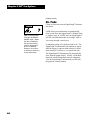
1. Ratchet Pinpointing
RATCHET PINPOINTING
ON
OFF
TO CHANGE PRESS ENTER
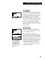
Tips - Use the ON
setting until experienced
at pinpointing.
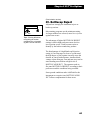
Pinpointing feature, automatically de-tunes for
easy target-center locating.
ON - Automatically aids in pinpointing. When the
TRIGGER is squeezed and held for pinpointing,
RATCHET PINPOINTING will shrink the size of
the signal as the loop is passed over the target area
several times. The signal will not fade completely
unless the loop is moved too far away from the
target center.
OFF - When OFF, the signal will remain original
size giving some indication of its size and shape.
Manual shrinking is completed by squeezing and
releasing the TRIGGER several times as the loop is
passed over the target. Manual shrinking can
completely eliminate the target. If the target no
longer responds after manual shrinking, move the
loop away from the target, squeeze and release the
TRIGGER, and again sweep the loop over the area.
If the target is a metal, it should again respond.
27
Chapter 5 XLT® Pro Options
(Audio section)
2. S.A.T. Speed
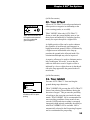
Self-Adjusting Threshold (auto-tune) smooths the
THRESHOLD, OFF (0), or ON (1-10).
S.A.T. SPEED
5
MIN
MAX
Tips - Recommended for
most conditions as it
provides greater stability
particularly in non-discriminate modes or when
sensitivity levels are
maximized. Typically,
faster S.A.T. SPEEDs
(higher numbers) improve
performance in more
mineralized ground.
Slower S.A.T. SPEEDs
(lower numbers) improve
performance in milder
ground conditions.
Without S.A.T. SPEED (a setting of 0), changes in
the ground (and the passage of time) will tend to
produce changes in the THRESHOLD sound. The
TRIGGER will have to be squeezed and released
repeatedly to maintain the THRESHOLD. This is
particularly noticeable in non-discriminate modes,
although S.A.T. SPEED will also tend to add
stability to discriminate modes. S.A.T. SPEEDs 1
through 10 will automatically correct for such
THRESHOLD changes.
S.A.T. (auto-tune) is a feature that has been used
on metal detectors dating back to the 1970's. It
adds a loop-motion requirement to modes which
are ordinarily non-motion. It is also known to
produce some variations in the responses to hot
rocks (rocks more mineralized than the surrounding ground) which change with different speed
selections.
Only enough S.A.T. SPEED required to maintain
stability is recommended. Typically normal coin
searching requires slower (lower number) speeds,
beach hunting and relic hunting require slightly
faster speeds (higher numbers), and prospecting
requires the fastest settings (highest numbers).
28
Chapter 5 XLT® Pro Options
(Audio section)
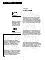
3. Tone I.D.
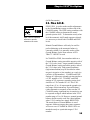
TONE I.D.
ON
OFF
TO CHANGE PRESS ENTER
Tips - Great for coin,
jewelry, and relic searching. Can be used in
combination with MIXED
MODE.
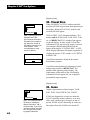
Assigns each V.D.I. number its own distinct tone
or pitch. Target ranges can easily be identified by
their sound. The higher the V.D.I. number, the
higher the pitch of their sound. Reject targets still
break up or "cut-out".
Tone I.D. is used in the discriminate or motion
modes. When ON, each V.D.I. target number has
its own audio frequency or pitch (191 different
pitches). The higher the V.D.I. number, the higher
the pitch. Where a target indicates on the V.D.I.
scale can be immediately recognized. The sound
that rejected targets produce will still be canceled
or modified (broken up) by the discriminate circuit.
The 191 different pitches or tones activated with
TONE I.D. cannot be adjusted as to their pitch.
Each V.D.I. number's sound is predetermined by
the factory and is not adjustable, nor will they shift
with TONE (AUDIO FREQUENCY) adjustments.
TRANSMIT FREQUENCY settings will add slight
variations to these tones.
(Audio section)
4. V.C.O.
V.C.O.
ON
OFF
TO CHANGE PRESS ENTER
Tips - The best aid
available for pinpointing.
Also can work well in
combination with MIXED
MODE to more easily
indicate when the nondiscriminate channel is
operating.
Voltage Controlled Oscillator produces a higher
pitched tone the stronger the target becomes.
Voltage Controlled Oscillator is a feature that will
only work in the non-discriminate modes. When it
is ON, the stronger the response the higher the
pitch of the sound. An excellent aid in pinpointing,
V.C.O. will only function when the trigger is
squeezed for pinpointing when activated in a discriminate mode.
D.C. SENSITIVITY settings will dramatically
change the performance of V.C.O. D.C. SENSITIVITY settings above a level of 35 may peak the
audio pitch too soon to allow V.C.O. to be useful.
D.C. SENSITIVITY settings of 35 or below (lower
numbers) are recommended.
29
Chapter 5 XLT® Pro Options
(Audio section)
5. Absolute Value
ABSOLUTE VALUE
ON
OFF
TO CHANGE PRESS ENTER
Tips - Turn ON if elongated Bigfoot or Goldfoot
loops (differentiating
designs) have been
installed.
Bigfoot, and Goldfoot loop use.
Absolute Value is included to enhance the performance of specialty loop (Bigfoot and Goldfoot)
designs. Absolute Value increases the detection
area of these loops in the non-discriminate modes
to their entire length. Use of Absolute Value is not
recommended for round-loop designs.
(Audio section)
6. Modulation
MODULATION
ON
OFF
TO CHANGE PRESS ENTER
Tips - If you have excellent
hearing and want to single
out deep targets by their
lower-volume responses,
use modulation. ON is the
default (standard setting)
for all factory Preset
Programs. If your hearing
isn't the best, the OFF
setting is recommended.
30
Allows motion modes to produce different volume
levels based on target depth.
Modulation is used in the discriminate or motion
modes. When ON, it allows the depth of the target
to dictate the volume of the response. Thus deep
targets can be easily recognized by their lowervolume sound. If OFF, the discriminate or motion
modes will produce the same volume of response
on all detected targets regardless of depth. The use
of MODULATION allows for the singling out of
deep targets in the standard discriminate mode. It
saves time by eliminating the checking of each
target with the depth indication in the pinpoint
mode.
Chapter 5 XLT® Pro Options
(G.E.B./Trac section)
7. AutoTrac
AUTO TRAC™ allows the instrument to automatically readjust the Ground Balance setting during
searching. This readjustment allows for natural
occurring changes in the ground mineral of an area.
By maintaining an accurate Ground Balance,
detection depth and stability are enhanced. AUTO
TRAC™ is recommended for typical search conditions. If, however, a great deal of decomposed
man-made iron is encountered, AUTO TRAC™
OFF, or a reduced AUTO TRAC™ SPEED is
advised. AUTO TRAC™ operation is affected by
TRAC INHIBIT.
AUTO TRAC
ON
OFF
TO CHANGE PRESS ENTER
Tips - Use ON for most
search conditions.
(G.E.B./Trac section)
8. Trac View
When ON, "TRACK" appears on right side of
display when AUTO TRAC™ makes adjustments
to the Ground Balance setting.
TRAC VIEW
ON
OFF
TO CHANGE PRESS ENTER
TRACK
-95
0
+95
Tips - Use when experimenting with different
TRAC SPEEDs to determine if, and how often,
AUTO TRAC™ automatically adjusts Ground
Balance.
TRAC VIEW offers a way to observe
Autotracking. When ON, "TRACK" will appear
momentarily on the right-hand side of the display
just above the SignaGraph™ while AUTO TRAC
is adjusting. This information is valuable when
attempting to determine an appropriate Trac Speed.
It may also be a valuable aid in determining the
relative ground conditions. Re-occurring
"TRACK" would indicate difficult ground. In
average ground it is desirable to see some tracking
occur (see TRAC SPEED).
31
Chapter 5 XLT® Pro Options
(G.E.B./Trac section)
9. Trac Speed
AUTO TRAC SPEED
8
MIN
MAX
Tips - It is desirable to
select a TRAC SPEED that
tracks the ground once
every three to five sweeps
of the loop however, this
may not be possible in
extremely consistent, or
extremely inconsistent
ground conditions, which
may TRAC less or more
than this desired standard.
32
Dictates when AUTO TRAC™ adjusts Ground
Balance.
Trac Speed allows adjustment of the amount of
ground mineral change required to cause
Autotracking to occur. At slower speeds (lower
numbers) it takes a significant change in the
ground to cause tracking to occur. At faster speeds
(higher numbers) it takes very little change in the
ground mineral to cause tracking to occur. The end
result, more tracking occurs at higher numbers than
at lower numbers. Too much tracking can cause
errors in the ground balance setting. Not enough
tracking can result in the ground balance setting
never catching up with changing ground. TRAC
VIEW is used to see how much tracking is occurring. Generally, a faster (higher number) TRAC
SPEED is needed for more consistent ground
conditions. Slower TRAC SPEEDS (lower numbers) is needed for more inconsistent ground
conditions. "TRACK" appearing every three to five
sweeps of the loop is the ideal setting when the
ground conditions will allow.
Chapter 5 XLT® Pro Options
(G.E.B./Trac section)
10. Trac Offset
AUTO TRAC OFFSET
+0
MIN
MAX
Tips - Recommended only
for experienced operators
who fully understand
ground rejection.
Allows AUTO TRAC™ to track ground minerals
either positive or negative in relationship to the
correct setting (under, or over kill).
TRAC OFFSET allows the AUTO TRAC™
feature to track the ground slightly more or less
than what would normally be considered perfect,
mostly for experts that prefer a slight offset.
A slightly positive offset can be used to enhance
the responses of small metals (gold nuggets) in
highly-mineralized ground. Positive is indicated by
a slight increase in threshold as the loop approaches the ground in the all-metal mode. Discrimination and depth may also be improved.
A negative offset may be used to eliminate particularly troublesome "hot rocks" in areas that are
otherwise difficult to search. Negative offset is
indicated by a loss or slight decrease in the threshold as the loop approaches the ground in the allmetal mode.
(G.E.B./Trac section)
11. Trac Inhibit
TRAC INHIBIT
ON
OFF
TO CHANGE PRESS ENTER
Tips - ON for most search
conditions, OFF for prospecting.
Prevents AUTO TRAC™ from tracking the
ground during target detection.
TRAC INHIBIT ON prevents the AUTO TRAC™
feature from altering Ground Balance during the
detection of targets. This prevents the possibility
of tracking to the corrosion associated with most
metals. TRAC INHIBIT ON is recommended for
most searching conditions. Some metals do not
corrode (GOLD) and since tracking is extremely
important in high mineral conditions, the ability to
turn TRAC INHIBIT OFF is available. OFF is
automatically selected in the Prospecting Program
and is recommended for prospecting.
33
Chapter 5 XLT® Pro Options
(G.E.B./Trac section)
12. Coarse G.E.B.
COARSE G.E.B.
50
MIN
(Manual Ground Balance) Allows viewing the
current automatic Ground Balance setting (Air/
Ground Balance) and/or manual overriding of the
automatic Ground Balance.
MAX
Tips - Use for controlled
reactions to specific
minerals or hot rocks.
COARSE & FINE G.E.B. (Ground Exclusion
Balance, or ground rejection) allows manual
override of the automatic balancing features to
select a specific Ground Balance setting.
COARSE allows major adjustments. FINE allows
minor adjustments near the COARSE setting.
Before attempting manual Ground Balance adjustments, turn off AUTO TRAC™ since it will alter any
manual changes you make. Manual Ground Balance
will begin at the setting selected by the automatic
(Air/Ground Balance) sequence. An Automatic Air/
Ground Balance performed after manual adjustment
will cancel the manual setting. To maintain a manual
setting, the Automatic Air/ Ground sequence must be
avoided by squeezing and releasing the TRIGGER
when, and if, the Air Balance instruction appears. Air
Balance instructions may appear during Basic Adjustment or Pro Options selections following the manual
adjustment.
When manually adjusting the Ground Balance, it is
necessary to make an adjustment in COARSE and/
or FINE, then squeeze and release the TRIGGER.
The TRIGGER can be held in, and the loop lowered and lifted over the ground to check for a
change in sound which would indicate imperfect
Ground Balance. To return to the Ground Balance
display for further adjustment, press either of the
ARROW controls. When perfectly Ground Balanced in a search mode, the TRIGGER can be
squeezed and held, and the loop lowered and lifted
with very little change in the threshold hum.
34
Chapter 5 XLT® Pro Options
(G.E.B./Trac section)
13. Fine G.E.B.
FINE G.E.B.
128
MIN
MAX
Tips - Use for controlled
reactions to specific
minerals or hot rocks.
FINE G.E.B. is used to make smaller adjustments
to the Ground Balance range on either side of the
COARSE setting. The FINE setting combines with
the COARSE setting to determine the actual
ground rejection level. To determine exactly what
level the automatic Air/Ground sequence selected,
it is necessary to check both COARSE and FINE
levels.
Manual Ground Balance will rarely be used for
perfect balancing as the automatic balance is
extremely reliable. It is generally used to offset
Ground Balance for the same reasons AUTO
TRAC™ OFFSET is used.
In COARSE or FINE, lower numbers indicate a
Ground Balance setting toward the negative side of
the V.D.I. scale (iron). Larger numbers indicate a
Ground Balance setting toward the positive side of
the V.D.I. chart (salt). Bad ground conditions
(high mineralization) may be described as either
magnetic (negative or low numbers) or conductive
(positive or high numbers). COARSE and FINE
settings of 0 represent a ground rejection similar to
a V.D.I. number of -95. COARSE and FINE
settings of 255 represent a ground rejection level
similar to a V.D.I. number of +10. This V.D.I.
range from -95 to +10 represents the ground rejection range of this instrument. If ground balance
(either automatic or manual) occurs near the 255
COARSE setting, significant loss in sensitivity can
be expected to targets which indicate in the V.D.I.
number range of 1 to 10. However, manual ground
balance doesn't exactly work like a discriminator,
where V.D.I. numbers are simply REJECTED.
The actual phase of Ground Balance is out of
sequence with most targets; thus some responses
will occur even if COARSE & FINE G.E.B. are
matched exactly to a particular targets V.D.I.
number.
35
Chapter 5 XLT® Pro Options
(Discrimination section)
14. Disc. Edit
DISC. EDIT
ACCEPT
REJECT
+72
Allows for changing which targets V.D.I. or reference numbers are ACCEPTed (detected), or
REJECTed, (discriminated out) within the current
Program you are using.
TO CHANGE PRESS ENTER
Tips - The factory Preset
Programs have all the
major DISCRIMINATION
EDIT set-ups already
defined and ready for you
to use. Major changes in
ACCEPT and REJECT
targets should be selected
by choosing one of these
factory programs. EDIT
allows customizing for
specific or unusual targets
you may want to either
ACCEPT or REJECT.
DISCRIMINATION - Will have a greater
impact on how the instrument operates
than any other feature. Audio Discriminate
ON/OFF is located in the BASIC
ADJUSTMENTS, (page 19).
DISC. EDIT and BLOCK EDIT are
exceptions to the key-stroke rule in that
they do not have a graphic control knob.
However, ENTER must still be pressed
before adjustments are possible.
Select DISC. EDIT and press ENTER. Now use
the ARROW controls to view the V.D.I. numbers
from negative -95 to positive +95 that appear on
the right side of the display. These are the same
reference numbers that are listed on the top righthand side of the control box (V.D.I. SCALE or
target chart). For each V.D.I. number, a √ will
appear to the left indicating whether the current
program will ACCEPT or REJECT targets that
display that number.
Use the ENTER control to change any desired
V.D.I. number to ACCEPT or REJECT status.
If you do not save the entire Program into a Custom position, the changes you make in EDIT are
only in use as long as you continue to use that
program. The only exception being the temporary
short-term or volatile memory as previously described. If you make EDIT changes in Coin, and
then switch to COIN & JEWELRY, you lose all
editing you completed in the Coin Program. Each
time a factory Preset Program is ENTERed, all
unsaved settings are over-written by the factory
recommended settings. Only the Custom Programs
will save your custom settings through Preset
Program selections.
Accepting certain V.D.I. numbers will have an
impact on detection depth, particularly for very
deep targets that are difficult for the display to
identify. Positive +95 is one of these V.D.I. numbers. Some Preset Programs are set so that the
positive +95 V.D.I. number is rejected. The display
uses positive +95 for many different types of
36
Chapter 5 XLT® Pro Options
targets it cannot readily identify. Therefore, if
positive +95 is ACCEPTed, questionable targets
may be dug that indicate this number and can
produce some interesting recoveries. A good tip
regarding positive +95: If a target indicates 95,
and the depth display indicates it as being fairly
deep; dig it. If the depth display indicates it as
being fairly shallow, it is more likely to be trash or
a hot rock.
The first 30 to 40 negative numbers below zero also
impact detection depth. Most iron indicates further
into the negative numbers. Thus the first 30 to 40
negative numbers can often be ACCEPTed without
digging much iron. ACCEPTing from the positive
numbers down as low as minus 30 to 40 has the
largest impact on the lower end of the positive
numbers. Sensitivity to small jewelry is increased
however, sensitivity to foil is also increased. On a
beach or in a park that has lots of small foil,
ACCEPTing down to minus 30 to 40 may not be
practical. While ACCEPTing these minus numbers,
a reduced sensitivity setting may help eliminate
some of these small bits of unwanted foil.
The detector sees metals electronically; thus some
valuable and non-valuable targets may look identical to the detector. To select ACCEPT and REJECT V.D.I. numbers is to gamble that the areas
you select for ACCEPT will be good targets, and
the area you select for REJECT will be trash
targets. A factory program which uses the law of
averages usually produces more good targets than
trash. The EDIT feature allows you to fine-tune the
ACCEPT and REJECT settings for your area and
types of desired targets, further improving these
odds.
ACCEPTINGing all V.D.I. numbers will produce
the best overall detection depth however, with the
amount of trash in most areas, searching with no
rejection is seldom practical. TONE I.D. and or
MIXED MODE are more practical choices. The
idea of discrimination is to ACCEPT V.D.I. numbers most likely to be valuables and to REJECT the
V.D.I. numbers most likely to be trash. Digging
ease, and acceptability in an area will also decide
the amount of ACCEPTed V.D.I. numbers desired.
No metal detector can reject all trash while accepting all valuables. The deeper you want to detect, the
more trash you will need to accept and dig.
37
Chapter 5 XLT® Pro Options
(Discrimination section)
15. BLOCK Edit
BLOCK EDIT
ACCEPT
REJECT
+72
TO CHANGE PRESS ENTER
Tips - If more than a few
V.D.I. numbers are to be
changed, use BLOCK
EDIT.
Speeds major EDIT changes by dragging ACCEPT
or REJECT with ARROW controls.
Allows major EDIT changes to be completed
quickly. EDIT is for individual V.D.I. number
changes and/or viewing of the current settings.
BLOCK EDIT is for changing multiple V.D.I.
numbers, or ranges.
CAUTION: You cannot view settings without
changing ACCEPT or REJECT status in BLOCK
EDIT.
Select BLOCK EDIT with the ARROW controls
and press ENTER. The ENTER control can be
used to select either ACCEPT or REJECT. The
ARROW controls can then be used to drag that
ACCEPT or REJECT status as far as desired
through the V.D.I. number range. When a V.D.I.
number or range of numbers appear that you want
set differently, stop dragging with the ARROWs,
press ENTER to change the ACCEPT / REJECT
status, and then drag that new status as far as you
desire. ENTER changes ACCEPT / REJECT;
ARROWS drag that ACCEPT / REJECT status;
ENTER again changes ACCEPT / REJECT;
ARROWS drag that new ACCEPT / REJECT
status, etc.
BLOCK EDIT not only saves time if large sections
of the V.D.I. target numbers are to be changed, it
also allows peace of mind in the certainty of how
all the V.D.I. numbers are set. In the same amount
of time it takes to view all the V.D.I. number's
current status in regular EDIT, you can set them
the way you desire in BLOCK EDIT.
38
Chapter 5 XLT® Pro Options
(Discrimination section)
16-17. Learn Accept/Reject
LEARN ACCEPT
ON
OFF
TO CHANGE PRESS ENTER
LEARN REJECT
ON
OFF
TO CHANGE PRESS ENTER
Tips - If searching for one specific
target and an exact sample is available,
BLOCK EDIT everything for reject then
use LEARN ACCEPT to accept only
that specific target. If using a standard
program and a specific unwanted trash
target is being detected, use the
LEARN REJECT to change the program to reject it.
CAUTION
If you do not return to the LEARN
selection screen and turn LEARN OFF,
the detector will continue to learn (ACCEPT or REJECT) every metal target it
encounters. Selecting LEARN OFF after
you have learned a target is extremely
important.
Iron alloys, such as steel bottle caps or
nails, should never be used for this
LEARN method of programming. Because of their inconsistent V.D.I. indications, iron alloys tend to scatter or otherwise confuse the discriminate program.
If this occurs, it is best to turn the detector OFF, back ON, and re-ENTER the
desired Program to return to the original
factory pre-set discriminate settings.
Specific target samples can be used to show or
teach the discriminator what metal targets you
desire ACCEPT or REJECT.
Select LEARN ACCEPT or LEARN REJECT with
the ARROW controls and press ENTER to turn
LEARN ON. The current selection is indicated by
the √ mark in square on the left of the display.
Once ON:
1. Squeeze and release the TRIGGER.
2. Show metal target sample or samples to
the instrument by sweeping them one at a
time in front of the loop until the desired
accept or reject sound is heard.
3. Press either ARROW control to return to
the LEARN selection display.
4. Press ENTER control to select LEARN
OFF.
5. Squeeze and release the TRIGGER to
return to a searching mode.
As with EDIT, LEARN changes will only be
temporary until saved in a Custom position.
If LEARN has been used to develop a discriminate
program, the ACCEPT or REJECT V.D.I. numbers
can be reviewed by using the EDIT feature.
39
Chapter 5 XLT® Pro Options
(Discrimination section)
18. Recovery Speed
RECOVERY SPEED
20
MIN
MAX
Tips - Use faster speeds
(higher numbers) for trashy
areas, slower speeds
(lower numbers) for low
trash areas and/or improved discrimination.
Speeds target responses, so several targets that are
close together can each respond.
When a metal is detected, it takes a fraction of a
second for the detector to process the signal before
it can respond to another metal target nearby. The
time it takes to process the first metal target signal
so that the second metal target signal can respond
is called RECOVERY SPEED.
There are advantages and disadvantages to fast
(high numbers) and slow (low numbers) RECOVERY SPEEDS. Faster RECOVERY SPEEDs work
well in high trash areas. However, they will have
some difficulties with very deep targets as well as
double responses on shallow targets. Slower
RECOVERY SPEEDs do not work very well in
high trash areas. However, they will have better
responses on very deep targets. Slower speeds also
have more definitive discrimination sounds. A
custom setting needs to be found that suits the
preferences of the individual and the conditions in
the area. As a general rule, the closer together the
metal targets are in an area, the faster the recovery
speed should be. The more spacing between targets, the slower the speed should be. Don't use the
fast speed if you don't need to.
In very trashy areas it is recommended to switch to
a loop smaller in size than the standard 9.5 inch
black loop. Smaller loops offer better separation
between targets. However, larger loops detect
deeper and cover more area with each pass. RECOVERY SPEED combined with a smaller loop
can be used to search severely trashy areas.
40
Chapter 5 XLT® Pro Options
(Discrimination section)
19. Bottlecap Reject
BOTTLECAP REJECT
4
MIN
MAX
Tips - If having difficulties
recognizing the broken
sounds of iron, try increasing BOTTLECAP REJECT.
Adjusts how strongly the instrument rejects or
breaks up on iron.
Most starting programs use the minimum setting.
As larger numbers are selected, more bias rejection
against iron occurs.
The advantage of higher BOTTLECAP REJECT
settings is that in high-trash areas more decisive
iron rejection occurs. Trash becomes easier to
identify by the broken sounds they produce.
The disadvantage of a high Bottlecap Rejection
setting is if an iron target is close to a good metal,
the high degree of bias against iron may cause the
detector to cancel both responses. Another disadvantage is that all targets, iron and non-iron, tend to
start sounding more broken at high levels of
BOTTLECAP REJECT. The operator needs to
fine tune BOTTLECAP REJECT according to their
preferences and the conditions being searched.
Some ground conditions make it difficult for the
instrument to recognize iron. BOTTLECAP REJECT allows compensation for these areas.
41
Chapter 5 XLT® Pro Options
(Display section)
20. Visual Disc.
When ON, REJECTed V.D.I. numbers and their
associated ICONS are prevented from appearing on
the display. When OFF, all V.D.I. numbers and
associated ICONS appear.
VISUAL DISC.
ON
OFF
TO CHANGE PRESS ENTER
Tips - Typically you're not
interested in the REJECTed target information.
Eliminating it from appearing reduces or cleans up
the display information you
must interpret. ON is
recommended for most
search conditions.
-95
0
+95
VISUAL DISC. "ON" eliminates both the V.D.I.
number and the ICON (NAIL, FOIL, PULL TAB,
etc.) of REJECTed V.D.I. numbers from appearing on the display. In other words if Visual Discrimination is ON, and a specific target is rejected
(for example 0-IRON) then 0-IRON will not
appear on the display. If VISUAL DISC. is OFF,
all the display indications will appear regardless of
whether the specific V.D.I. number is ACCEPTed
or REJECTed.
Visual Discrimination is based on the current
discriminate program.
Visual Discrimination has the advantage of eliminating a large number of REJECTed V.D.I.
numbers from appearing on the display. The
disadvantage is that much of the visual display
information will not appear for you to interpret
questionable target responses.
(Display section)
21. Icons
ICONS
ON
OFF
TO CHANGE PRESS ENTER
42
Tips - The ICONS provide a
quick way of reading the
display information. ON is
recommended. If you do not
use these ICONS, selecting
OFF will speed the remaining display indications.
Graphic representation of metal targets, "NAIL,
FOIL, PULL TAB, SCREW CAP, COINS".
ICONS are designed for average use inside the
USA. If searching in other countries, or in areas
where such common types of targets are not expected, ICONS may be distracting. In such cases,
this option allows the ICONS to be turned off.
Chapter 5 XLT® Pro Options
(Display section)
22. V.D.I. Sensitivity
V.D.I. SENSITIVITY
80
MIN
MAX
Tips - Lower V.D.I. SENSITIVITY level (smaller
numbers) offer fewer and
more reliable display
indications. However,
some deep targets may or
may not respond with a
display indication. Higher
V.D.I. SENSITIVITY levels
(higher numbers) produce
more display indications,
but less reliability. Levels
of 86 and above produce a
third V.D.I. digit (.0),
providing greater resolution.
+19.8
-95
5¢
0
Third number (.8)
+95
Controls how strong a target must respond to
produce a display indication, and controls a third
digit (fraction) of the V.D.I. number.
V.D.I. Sensitivity controls the intensity (strength)
of the target signal needed to activate the display
indications. A low V.D.I. Sensitivity setting would
require a strong target signal to trigger the display
indications. A higher V.D.I. Sensitivity setting
would require very little target signal to trigger the
display indications.
To provide greater specific target resolution, levels
of 86 and above will provide a third V.D.I. digit
(.0) to better evaluate targets. During EDIT only
the first two digits can be programmed ACCEPT or
REJECT.
As with all sensitivity levels, if set too high for the
area, the detector will become unstable and the
display indications unreliable.
Low ground mineralization is typically a good
indication that high V.D.I. sensitivity settings are
appropriate. Heavy mineralization or electrical
interference are conditions where a lower V.D.I.
Sensitivity setting is appropriate.
This feature is designed to allow adjustment of the
display stability. However, because the
instrument's display and audio tone are closely
associated in many of the audio modes, the V.D.I.
Sensitivity may increase or decrease overall audio
sensitivity.
43
Chapter 5 XLT® Pro Options
(Display section)
23. D.C. Phase
Measurement of the ground mineralization, or
measuring the phase (V.D.I. reference number) of a
specific metal target during pinpointing.
D.C. PHASE
ON
OFF
TO CHANGE PRESS ENTER
Tips - In specific ground
conditions, certain Basic
Adjustments and Pro
Options may produce
better performance. By
measuring the ground and
taking notes, such conditions may also be recognized in other areas and
dealt with by using similar
settings.
10.5"
-82.2
+ - 1 2 - + - + - 9 - + - + - 6 - + - + - 3 - + - + - 0
The D.C. Phase of the ground has a relationship
to the proper Ground Balance setting. This is of
particular interest to those who use the optional
COARSE or FINE G.E.B. (Manual Ground
Balance). Manual Ground Balance has a range
that covers V.D.I. numbers from -95 - +10. A
Manual Ground Balance Coarse setting of 0
equals a D.C. PHASE of negative -95. A Coarse
setting of 255 equals a D.C. Phase of +10. As
mentioned under COARSE and FINE G.E.B.,
Ground Balance is not the same as EDITing
these V.D.I. numbers for REJECT. However, if
your ground measures -90, ACCEPTing V.D.I. 90 will produce operational problems as the
detector will see the ground as a target. With the
same logic, if a target measures -90, and the
ground measures -90, and the detector is Ground
Balanced to this -90 ground, such a target will be
virtually invisible to the detector. These conditions
would be extremely rare however; the point is
there must be a difference between the target and
the ground for the target to be detected.
44
When D.C. PHASE is ON, and the TRIGGER
squeezed and released, normal searching begins.
When a target is located, or when the operator
wants to measure a target or the ground, the TRIGGER is squeezed and held as if to pinpoint. When
the loop is held stationary over the target or ground,
the D.C. PHASE is shown on the upper-right side
of the display. The depth reading can be used to
help center the loop over a target for more accurate
indications. The audio tone will also assist in
centering the loop over the target.
Metal targets in the ground will produce a measurement which represents the target indication ± the
ground measurement. To measure the target alone,
move the loop off to one side (being sure to hold
the loop directly on top of the ground mineral), and
release and re-squeeze the trigger. Then move the
loop back over the target. This should allow a
proper D.C. PHASE reading for the target alone.
The relationship between D.C. PHASE, Ground
Balance, V.D.I. number and Discrimination is
complex. Results are not always repeatable in
varied ground conditions. Ground and target responses can distort the detection field of the loop in
a number of ways, by bending, reflecting, absorbing
and thus altering the phase and amplitude the
detector measures. This in turn produces inconsistencies in the relationships of these features.
Chapter 5 XLT® Pro Options
(Display section)
24. Accumulate
GRAPH ACCUMULATE
ON
OFF
TO CHANGE PRESS ENTER
Tips - ON is suggested,
since it takes several
sweeps of information to
recognize trends.
If ACCUMULATE is OFF, and AVERAGE
is OFF, then SINGLE SWEEP is active.
SINGLE SWEEP displays SignaGraph™
information received during the current sweep
of the loop, no more and no less. The next
sweep of the loop will clear all information
from the SignaGraph™ and list the information received only within that sweep. Fade is
not needed in the SINGLE SWEEP mode as
each pass of the loop will clear the display
and provide current information automatically. Several SignaGraph™ indication
samples occur during each sweep of the loop.
It is therefore normal to see one or more
SignaGraph™ bars, even in the SINGLE
SWEEP mode.
GRAPH AVERAGING
ON
OFF
TO CHANGE PRESS ENTER
Tips - Most beneficial
when used in combination
with ACCUMULATE.
AVERAGE ON is suggested as it reduces
indications uncharacteristic of a particular target,
which may occur due to
loop angle or target
positioning in the ground.
ON combines SignaGraph™ information over
multiple loop passes, OFF shows SignaGraph™
information only from the last sweep of the loop.
Accumulate allows the SignaGraph™ to continually
collect information. This collecting of information
continues from one sweep of the loop to the next.
Eventually, if only ACCUMULATE is selected,
the SignaGraph™ will completely fill, requiring
that the TRIGGER by squeezing and releasing to
clear it so that further information may be viewed.
FADE is suggested to be used in combination with
ACCUMULATE so that non-current information
gradually disappears and excessive TRIGGERing is
not required. FADE will gradually reset or clear the
SignaGraph™ to eliminate old information.
(Display section)
25. Average
Emphasizes the most common or predominate
SignaGraph™ indications.
AVERAGE does not necessarily allow showing of
all the available information on the SignaGraph™.
It averages the information received, and shows this
average on the SignaGraph™. When used in combination with ACCUMULATE it has more information to average, which results in more accurate
indications of trends. FADE is suggested to clear
the display of old information, rather than excessive
TRIGGERing.
45
Chapter 5 XLT® Pro Options
(Display section)
26. Fade
Clears or fades non-current SignaGraph™ information (bars).
FADE RATE
7
MIN
MAX
Tips - Recommended
for all but the SINGLE
SWEEP mode. Adjust
the rate of FADing so
that you have time to
view the SignGraph™
prior to it resetting.
However, do not set it
so slow as to show noncurrent information.
46
FADE allows past information to automatically
clear or fade from the SignaGraph™. Without Fade,
or with too slow of a FADE rate, the SignaGraph™
will fill with information that is no longer valid as
you sweep through a search area.
A minimum setting of 0 equals no fade at all. The
SignaGraph™ information will continue to appear
until the trigger is squeezed and released. A maximum setting of 14 selects a very quick fade rate.
The SignaGraph™ information will automatically
clear from the graph quickly. Ideally, a Fade Rate
should be selected that allows time to adequately
view the SignaGraph™ information yet still clear
the graph in a timely manner.
Chapter 5 XLT® Pro Options
(Signal, Transmit, Receive))
27. Transmit Boost
TRANSMIT BOOST
ON
OFF
TO CHANGE PRESS ENTER
Tips - Use ON unless
"OVERLOAD" is often
noted on the display, in
which case the OFF
setting should be
selected. Make sure the
OVERLOAD indication
is not caused by a large
metal target, that it is
caused by the ground
minerals.
Selects the intensity of the signal transmitted from
the loop.
There is a transmit and a receive coil within the
loop housing. If too much signal is transmitted for
the ground conditions (magnetic and/or conductive
ground), the signal will saturate the receiver and
thus eliminate good ground penetration (depth). By
turning OFF the TRANSMIT BOOST, ground
penetration in most cases will return. The receive
signal can then be optimized using PREAMP
GAIN, to provide the best depth possible in such
extreme ground conditions.
When "OVERLOAD" regularly appears on the
display, there are either very large strong metal
targets present or the ground mineralization is such
that the detector cannot properly operate. Sweeping
the loop higher above the specific OVERLOAD
response will identify a target. When OVERLOAD
appears on the display consistently due to ground
minerals, selection of TRANSMIT BOOST OFF
will improve depth and stability. During OVERLOAD the detector is not capable of responding to
metal targets. The OFF setting in most cases will
resolve such difficulties and provide detection
capabilities in extreme conditions.
Every time the TRANSMIT BOOST is altered, the
detector needs to be Air/Ground Balanced. Once in
a search mode, simply press ENTER to Air/Ground
Balance.
47
Chapter 5 XLT® Pro Options
(Signal, Transmit, Receive))
28. Transmit Frequency
TRANSMIT FREQUENCY
4
MIN
MAX
Tips - Use level number
"4" (6592.5 Hz) unless
interference results from
other detectors. Move
away from level "4" only
far enough to prevent
such interference.
Alters the normal operating frequency (6592.5 Hz)
to avoid interference from other metal detectors
operating close by. Operating frequency is the
frequency the detector transmits and receives its
signal.
Lower numbers equal
lower frequencies,
1 = 6027.5 Hz
2 = 6204.7 Hz
3 = 6392.7 Hz
4 = 6592.5 Hz
Higher numbers equal
higher operating
frequencies,
5 = 6805.2 Hz
6 = 7032.0 Hz
7 = 7274.5 Hz
Other metal detectors operating at the same frequency will cause interference. By shifting to a
different frequency such interference can be
avoided from detectors operating nearby.
The best performance will be achieved at the
standard number "4" setting. If however, you
cannot search due to interference from other detectors, use an alternate frequency.
Remember that once the trigger is squeezed and
released to return to a search mode, the last option
used can be accessed by pressing either of the arrow
controls. This ARROW RETURN feature can be
used to handily change TRANSMIT FREQUENCIES during a competition hunt.
48
Chapter 5 XLT® Pro Options
(Signal, Transmit, Receive))
29. Preamp Gain
Selects the intensity of the signal received from the
loop.
PREAMP GAIN
2
MIN
MAX
Tips - Higher levels
increase detection depth.
However, the detector
must be stable to be able
to recognize a target.
OVERLOAD should not
appear on the display
when only ground minerals are present.
PREAMP GAIN (called Signal Balance on some
models) is used to promote stability and performance. Like a sensitivity control, too much
PREAMP GAIN will result in unstable operation
and unreliable indications. Unlike a sensitivity
control, PREAMP GAIN will have a substantial
effect on OVERLOAD.
For maximum detection depth, fine tune the
PREAMP GAIN to the highest number setting
without causing OVERLOAD, and/or unstable
operation. More adjustment levels (range) are
available than what may be usable. You may never
encounter an area where maximum PREAMP
GAIN can be used. Electrical interference may
make it difficult to receive an Air Balance at high
PREAMP GAIN settings.
Selections such as MIXED MODE or AUDIO
DISC OFF may not allow as high a PREAMP
GAIN level as other selections. This is normal as
some of these modes naturally see more targets and
ground, and they may still provide superior performance and depth even with the lower PREAMP
GAIN selection.
If TRANSMIT BOOST OFF has been selected, it is
particularly advisable to fine tune PREAMP GAIN.
Every time the PREAMP GAIN level is changed,
the detector needs to be re-ground balanced. Once
in an operating mode, simply press ENTER to reground balance.
49
Preset Program Settings
COIN
BASIC ADJUSTMENTS:
TARGET VOLUME
AUDIO THRESHOLD
TONE (AUDIO FREQ.)
AUDIO DISC.
SILENT SEARCH
MIXED-MODE
A.C. SENSITIVITY
D.C. SENSITIVITY
BACKLIGHT
VIEWING ANGLE
PRO OPTIONS:
"AUDIO"
RATCHET PINPOINT
S.A.T. SPEED
TONE I.D.
V.C.O.
ABSOLUTE VALUE
MODULATION
"G.E.B./TRAC" AUTO TRAC™
TRAC VIEW
AUTO TRAC™ SPEED
AUTO TRAC™ OFFSET
TRAC INHIBIT
COARSE G.E.B.
FINE G.E.B.
"DISCRIMINATION"
DISC. EDIT
Reject
Accept
Reject
Accept
Reject
BLOCK EDIT
LEARN ACCEPT
LEARN REJECT
RECOVERY SPEED
BOTTLECAP REJECT
VISUAL DISC.
"DISPLAY"
ICONS
V.D.I. SENSITIVITY
D.C. PHASE
GRAPH AVERAGING
GRAPH ACCUMULAT
FADE RATE
"SIGNAL"
TRANSMIT BOOST
TRANSMIT FREQ.
PREAMP GAIN
50
COIN&
JEWELRY
JEWELRY
&BEACH
RELIC
PROSPECT
56
23
231
ON
OFF
OFF
64
30
0
25
56
23
231
ON
OFF
OFF
64
30
0
25
56
23
231
ON
OFF
OFF
64
30
0
25
56
23
226
ON
OFF
OFF
64
35
0
25
56
23
221
OFF
OFF
OFF
64
45
0
25
ON
5
OFF
OFF
OFF
ON
ON
OFF
8
0
ON
AUTO
AUTO
ON
5
OFF
OFF
OFF
ON
ON
OFF
8
0
ON
AUTO
AUTO
ON
9
OFF
OFF
OFF
ON
ON
OFF
14
0
ON
AUTO
AUTO
OFF
7
OFF
OFF
OFF
ON
ON
OFF
14
+1
ON
AUTO
AUTO
OFF
9
OFF
OFF
OFF
ON
ON
ON
18
+1
OFF
AUTO
AUTO
-95-+9
+10-+27
+28-+49
+50-+94
+95
Same Edit
OFF
OFF
20
4
ON
ON
80
OFF
ON
ON
7
ON
4
2
-95--31
-30--1
0-+7
+8-+95
NA
Same Edit
OFF
OFF
20
4
ON
ON
80
OFF
ON
ON
7
ON
4
2
-95--31
-30--1
0-+7
+8-+95
+95
Same Edit
OFF
OFF
20
1
ON
ON
85
OFF
ON
ON
7
ON
4
2
-95--30
-29--+95
NA
NA
NA
Same Edit
OFF
OFF
20
1
ON
OFF
85
OFF
ON
ON
7
ON
4
2
-95--20
-19-+94
+95
NA
NA
Same Edit
OFF
OFF
20
1
ON
OFF
85
OFF
ON
ON
7
ON
4
2
Custom Program Settings
Custom 1
Custom 2
Custom 3
Custom 4
NOTES
BASIC ADJUSTMENTS:
TARGET VOLUME
AUDIO THRESHOLD
TONE (AUDIO FREQ.)
AUDIO DISC.
SILENT SEARCH
MIXED-MODE
A.C. SENSITIVITY
D.C. SENSITIVITY
BACKLIGHT
VIEWING ANGLE
PRO OPTIONS:
"AUDIO"
RATCHET PINPOINT
S.A.T. SPEED
TONE I.D.
V.C.O.
ABSOLUTE VALUE
MODULATION
"G.E.B./TRAC" AUTO TRAC™
TRAC VIEW
AUTO TRAC™ SPEED
AUTO TRAC™ OFFSET
TRAC INHIBIT
COARSE G.E.B.
FINE G.E.B.
"DISCRIMINATION"
DISC. EDIT
Reject
Accept
Reject
Accept
Reject
BLOCK EDIT
LEARN ACCEPT
LEARN REJECT
RECOVERY SPEED
BOTTLECAP REJECT
VISUAL DISC.
"DISPLAY"
ICONS
V.D.I. SENSITIVITY
D.C. PHASE
GRAPH AVERAGING
GRAPH ACCUMUL.
FADE RATE
TRANSMIT BOOST
"SIGNAL"
TRANSMIT FREQ.
PREAMP GAIN
51
Glossary
Glossary
All-Metal: Any mode or control setting allowing total acceptance of all metal types, iron, aluminum, tin, nickel,
gold, brass, lead, copper, silver etc...
Audio ID: Circuitry which produces different audio tones (pitch) for different target's conductivity.
Black Sand: One of the most extreme components of non-conductive, negative ground minerals. Magnetic.
Also called Magnetite (Fe304) or magnetic iron oxide.
Cache: Any intentionally buried or secreted hoard of valuables.
Conductive Salts: One of the major mineral types which make up the positive ground minerals. Wet ocean
salt/sand will produce a positive response due to its similar conductivity to metal.
Conductivity: The measure of a metal target's ability to allow eddy currents on its surface.
Depth: The greatest measure of a metal detectors ability to transmit an electromagnetic field into the ground.
De-tuning: Method of manually or automatically desensitize a metal detector so that it may locate the center
of a target.
Discrimination: Circuitry which ignores or otherwise indicates, a specific target based on its conductivity/
phase.
Drift: A loss or increase in threshold caused by temperature, time, or battery condition.
Eddy Currents: Small circulating currents of electricity.
Ferrous: Descriptive of any iron or iron bearing material.
Frequency: The number of complete alternating current cycles produced by the transmit oscillator per second.
Ground Balance: A state of operation in which specialized circuitry can ignore the masking effect ground
minerals have over metal targets.
Hot Rock: A rock which contains a higher concentration of mineralization than the surrounding ground.
Matrix: Refers to the total volume (average) of ground penetrated by a metal detector.
Menu: Series of listings and prompts on a visual display designed to aid the operator in feature selection.
Metal: Metallic substances: iron, foil nickel, aluminum, gold, brass, copper, silver, etc...
Microprocessor: An electronic component that can be programed to perform certain electronic functions.
Mineralized Ground: Any soil containing conductive or magnetic components.
Mode: A condition of operation selected by the operator for specific functions.
Motion Mode: Any mode that requires loop movement to respond to metals.
Non-ferrous: Not of iron, any metal that is not iron.
Non-Motion Mode: Any mode of operation that doesn't require movement of the loop to respond to metal
targets.
Phase: The length of time between eddy current generation sustained on a metals surface and the resulting
secondary electromagnetic field effect on the loops receive winding.
Pinpointing: Finding the exact center of a metal target.
Reject: An indication of a target non-acceptance by silence or a broken sound.
Sensitivity: The measure or capacity of a metal detector to perceive changes in conductivity within the loops
detection pattern.
Signal: An audio or display response alerting the operator that a target has been detected.
Stability: The ability of a metal detector to maintain smooth predictable performance.
Target: Refers to any object that causes an audio or display indication.
Visual ID: A feature which creates a visual indication to aid in identification of a target.
VLF (Very Low Frequency): A metal detector that operates in the 3-30 kHz frequency range.
52
Owner Info
WARRANTY TRANSFER
If for any reason you should sell your Spectrum XLT® prior to the date the warranty
expires, the remaining warranty is transferable. This transfer is authorized by calling 1-800547-6911, and getting an Authorization Number.
Simply fill out the following information, including the Authorization Number, seal it in a
stamped envelope, and send it to White's Electronics, 1011 Pleasant Valley Road, Sweet Home,
Oregon 97386. The remaining warranty period will then be available to the new owner.
The Warranty Statement applies to both the original owner as well as the second owner.
WARRANTY TRANSFER
Original Owner:
Name: __________________________________________________________
Address (Which appears on the original warranty card):
________________________________________________________________
________________________________________________________________
Instrument Serial Number: __________________________________________
Date Code: ______________________________________________________
Original Purchase Date:_____________________________________________
New Owner:
Name: __________________________________________________________
Address: ________________________________________________________
________________________________________________________________
________________________________________________________________
Comments: ______________________________________________________
________________________________________________________________
________________________________________________________________
________________________________________________________________
________________________________________________________________
Distributor Authorization Code: _______________________________________________
53
Owner Info
WHITE'S ELECTRONICS INC.
LIMITED WARRANTY STATEMENT
If within two years (24 months) from the original date of purchase, your White's detector fails due
to defects in either material or workmanship, White's will repair or replace at its option, all necessary parts
without charge for parts or labor.
Simply return the complete detector to the Dealer where you purchased it, or to your nearest
Authorized Service Center. The unit must be accompanied by a detailed explanation of the symptoms of
the failure. You must provide proof of date-of-purchase before the unit is serviced.
This is a transferable manufacturer warranty, which covers the instrument two years from the
original purchase date, regardless of the owner.
Items excluded from the warranty are non-rechargeable batteries, accessories that are not standard
equipment, shipping / handling costs outside the continental USA, Special Delivery costs (Air Freight,
Next Day, 2nd Day, Packaging Services, etc.) and all shipping / handling costs inside the continental USA
90 days after purchase.
White's registers your purchase only if the Sales Registration Card is filled out and returned to the
factory address soon after original purchase for the purpose of recording this information, and keeping you
up-to-date regarding White's ongoing research & development.
The warranty does not cover damage caused by accident, misuse, neglect, alterations,
modifications, unauthorized service, or prolonged exposure to corrosive compounds, including salt.
Duration of any implied warranty (e.g., merchantability and fitness for a particular purpose) shall
not be longer than the stated warranty. Neither the manufacturer or the retailer shall be liable for any
incidental or consequential damages. Some states however, do not allow the limitation on the length of
implied warranties, or the exclusion of incidental or consequential damages. Therefore, the above
limitations may not apply to you.
In addition, the stated warranty gives you specific legal rights, and you may have other rights
which vary from state-to-state.
The foregoing is the only warranty provided by White's as the manufacturer of your metal detector.
Any "extended warranty" period beyond two years, which may be provided by a Dealer or other third
party on your detector, may be without White's authority, involvement and consent, and might not be
honored by White's.
54
White's Service Centers
White's Authorized Service Centers
1
White"s Electronics
1011 Pleasant Valley Rd.
Sweet Home, OR 97386
(541) 367 6121
Fax (541) 367 6629
[email protected]
2
3
Electronic Exploration
700 South Main
Lombard, IL 60148
(630) 620-0618
Fax (630) 620-1005
Tol Free 800 392-3223*
[email protected]
Geoquest
106 US Hwy 46
Saddlebrook, NJ 07663
(973) 772-7443
Fax (973) 772-7773
Tol Free 877 772-7443*
[email protected]
1
3
2
4
4
Centreville Electronics
13810 B Braddock Rd.
Centreville, VA 20121
(703) 631-0202
Fax (703) 222-8625
Tol Free 888 645-0202*
[email protected]
White’s reputation has been built on quality products backed by
quality service. Our Factory Authorized Service Centers are factory trained
and equipped. They offer the same quality service as the factory. Service
before and after the sale is the cornerstone of our customer relations.
Before shipping detectors for service
A. Contact your Dealer. There may be a quick,
simple fix or explanation that will prevent having
to send the detector in for service.
D. Always include a letter of explanation about
your concerns, even if you have talked to the
Service Center by telephone.
B. Double check the obvious, such as batteries,
and try the detector in another area to be sure there
isnot interference.
E. Take care in packaging instruments for shipping. Always insure your package.
C. Be sure to send all necessary parts with your
detector, such as batteries and holders, as these
items can result in symptoms.
55
Notes
Notes
56