1
ARMY TM 9-1005-319-23&P
AIR FORCE TO 11 W3-5-5-42
Supersedes Copy Dated August 1987
TECHNICAL MANUAL
UNIT AND DIRECT SUPPORT MAINTENANCE MANUAL
(INCLUDING REPAIR PARTS AND SPECIAL TOOLS LIST)
INTRODUCTION
1-1
UNIT MAINTENANCE
INSTRUCTIONS
2-1
DIRECT SUPPORT
MAINTENANCE
INSTRUCTIONS
3-1
MAINTENANCE OF
AUXILIARY EQUIPMENT
4-1
REFERENCES
A-1
MAINTENANCE
ALLOCATION CHART
B-1
REPAIR PARTS AND SPECIAL
TOOLS LIST
C-1
EXPENDABLE/DURABLE
SUPPLIES AND
MATERIALS LIST
D-1
ILLUSTRATED LIST OF
MANUFACTURED ITEMS
E-1
ALPHABETICAL INDEX
Index-1
DISTRIBUTION STATEMENT. Approved for public release; distribution is unlimited.
DEPARTMENTS OF THE ARMY AND AIR FORCE
MAY 1991
ARMY TM 9-1005-319-23&P
AIR FORCE TO 11W3-5-5-42
CHANGE
HEADQUARTERS
DEPARTMENTS OF THE ARMY
AND AIR FORCE
Washington D.C., 9 April 1997
NO. 5
UNIT AND DIRECT SUPPORT MAINTENANCE MANUAL
(INCLUDING REPAIR PARTS AND SPECIAL TOOLS LIST)
RIFLE, 5.56MM, M16A2 W/E
(1005-01-128-9936) (EIC:4GM)
TM 9-1005-319-23&P, May 1991, is changed as follows:
1. Remove old pages and insert new pages as indicated below.
2. New or changed material is indicated by a vertical bar adjacent to the material.
3. New or changed illustrations are indicated by a miniature pointing hand highlighting the change.
Remove Pages
a thru ii
1-1 and 1-2
1-4.1 thrul-6
2-12
2-15 and 2-16
2-31 and 2-32
2-35 thru 2-36.1/(2-36.2 blank)
2-49 and 2-50
2-57 and 2-58
3-25 and 3-26
3-29 and 3-30
3-45 and 3-46
3-57 thru 3-62
3-82 thru 3-84
4-1 and 4-2
A-1 and A-2
C-5 thru 1-12
E-1 and E-2
None
Insert Pages
a thru ii
1-1 and 1-2
1-4.1 thru 1-6
2-12
2-15 and 2-16
2-31 and 2-32
2-35 thru 2-36.1/(2-36.2 blank)
2-49 and 2-50
2-57 and 2-58
3-25 and 3-26
3-29 and 3-30
3-45 and 3-46
3-57 thru 3-62
3-82 thru 3-84
4-1 and 4-2
A-1 and A-2
C-5 thru 1-7/(I-8 blank)
E-1 and E-2
E-7/(E-8 blank)
4. File this change sheet in the front of the publication for reference purposes.
By Order of the Secretary of the Army:
DENNIS J. REIMER
General, United States Army
Chief of Staff
Official:
JOEL B. HUDSON
Administrative Assistant to the
Secretary of the Army
03287
DISTRIBUTION:
To be distributed in accordance with the initial distribution number (IDN) 400020, requirements for TM
9-1005-319-23&P.
ARMY TM 9-1005-319-23&P
AIR FORCE TO 11W3-5-5-42
CHANGE
HEADQUARTERS
DEPARTMENTS OF THE ARMY
AND AIR FORCE
Washington D.C., 5 May 1995
No. 4
UNIT AND DIRECT SUPPORT MAINTENANCE MANUAL
(INCLUDING REPAIR PARTS AND SPECIAL TOOLS LIST)
RIFLE, 5.56MM, M16A2 W/E
(1005-01-128-9936) (EIC:4GM)
TM 9-1005-319-23&P, May 1991, is changed as follows:
1. Remove old pages and insert new pages as indicated below.
2. New or changed material is indicated by a vertical bar adjacent to the material.
3. New or changed illustrations are indicated by a miniature pointing hand highlighting the change.
Remove Pages
a thru iv
1-0.1/(1-0.2 blank) thru 1-6
2-1 thru 2-8
2-11 and 2-12
2-17 thru 2-20
2-31 thru 2-34
None
2-48 thru 2-50
2-53 thru 2-54
2-59 thru 2-62
2-69 thru 2-72
3-1 and 3-2
3-5 thru 3-8
3-11 thru 3-16
3-19 and 3-20
3-39 and 3-40
3-43 and 3-44
3-47 thru 3-48
3-55 and 3-56
3-65 thru 3-70
3-73 thru 3-76
3-83 thru 3-88
3-93 thru 3-96
3-101 thru 3-103/(3-104 blank)
Insert Pages
a thru iv
1-0.1/(1-0.2 blank) thru 1-6
2-1 thru 2-8
2-11 and 2-12
2-17 thru 2-20
2-31 thru 2-34
2-36.1/(2-36.2 blank)
2-48 thru 2-50
2-53 thru 2-54
2-59 thru 2-62
2-69 thru 2-73/(2-74 blank)
3-1 and 3-2
3-5 thru 3-8
3-11 thru 3-16
3-19 and 3-20
3-39 and 3-40
3-43 and 3-44
3-47 thru 3-48
3-55 and 3-56
3-65 thru 3-70.1/(3-70.2 blank)
3-73 thru 3-76.1/(3-76.2 blank)
3-83 thru 3-88
3-93 thru 3-96
3-101 thru 3-103/(3-104 blank)
Remove Pages
4-1 and 4-2
4-9 thru 4-11/(4-12 blank)
A-1 and A-2
B-5 thru B-8
C-1 and C-2
C-7 and C-8/(C-9 blank)
Fig C-1 thru Fig C-2
C-5-1 thru Fig C-9
C-10-1 thru C-11-2
C-12-1 thru Fig C-17-1
I-1 thru 1-10
D-3 and D-4
E-5/(E-6 blank)
Cover
Insert Pages
4-1 and 4-2
4-9 thru 4-11/(4-12 blank)
A-1 and A-2
B-5 thru B-8
C-1 and C-2
C-7 and C-8/(C-9 blank)
Fig C-1 thru Fig C-2
C-5-1 thru Fig C-9
C-10-1 thru C-11-2
C-12-1 thru Fig C-17-1
1-1 thru 1-12
D-3 thru D-5/(D-6 blank)
E-5 and E-6
Cover
4. File this change sheet in the front of the publication for reference purposes.
By Order of the Secretary of the Army:
GORDON R. SULLIVAN
General, United States Army
Chief of Staff
Official:
JOEL B. HUDSON
Acting Administrative Assistant to the
Secretary of the Army
00175
DISTRIBUTION:
23&P.
To be distributed in accordance with DA Form 12-40-E, block 0020 requirements for TM 9-1005-319-
ARMY TM 9-1005-319-23&P
AIR FORCE TO 11W3-5-5-42
CHANGE
HEADQUARTERS
DEPARTMENTS OF THE ARMY
AND AIR FORCE
Washington D.C., 3 February 1994
No. 3
UNIT AND DIRECT SUPPORT MAINTENANCE MANUAL
(INCLUDING REPAIR PARTS AND SPECIAL TOOLS LIST)
RIFLE, 5.56MM, M1 6A2 W/E
(1005-01-128-9936) (EIC:4GM)
TM 9-1005-319-23&P, May 1991, is changed as follows:
1. Remove old pages and insert new pages as indicated below.
2. New or changed material is indicated by a vertical bar adjacent to the material.
3. New or changed illustrations are indicated by a miniature pointing hand highlighting the change.
Remove Pages
a thru iv/v(blank)
1-3 thru 1-6
2-3 and 2-4
2-13 thru 2-18
2-21 thru 2-24
2-27 and 2-28
2-47 and 2-48
2-53 and 2-54
2-57 thru 2-60
2-63 thru 2-71/(2-72 blank)
3-39 and 3-40
3-57 and 3-58
3-77 thru 3-82
4-1 and 4-2
4-5 thru 4-10
B-5 thru B-8
C-7 and C-8/(C-9 blank)
Fig C-1 thru Fig C-2
C-5-1 thru Fig C-9
C-10-1 thru Fig C-14
C-15-1 thru C-17-1
I-1 thru 1-10
Cover
Insert Pages
a thru iv/v(blank)
1-0.1/(1-0.2 blank)
1-3 thru 1-6
2-3 and 2-4
2-13 thru 2-18.2
2-21 thru 2-24
2-27 and 2-28
2-47 thru 2-48
2-53 and 2-54
2-57 thru 2-60
2-63 thru 2-72
3-39 and 3-40
3-57 and 3-58
3-77 thru 3-82
4-1 and 4-2
4-5 thru 4-10
B-5 thru B-8
C-7 and C-8/(C-9 blank)
Fig C-1 thru Fig C-2
C-5-1 thru Fig C-9
C-10-1 thru Fig C-14
C-15-1 thru C-17-1
I-1 thru I-10
Cover
4. File this change sheet in the front of the publication for reference purposes.
By Order of the Secretary of the Army:
GORDON R. SULLIVAN
General. United States Army
Chief of Staff
Official
MILTON H HAMILTON
Administrative Assistant to the
Secretary of the Army
05909
DISTRIBUTION:
23&P.
To be distributed in accordance with DA Form 12-40-E, Block 0020, requirements for TM 9-1005-319-
ARMY TM 9-1005-319-23&P
AIR FORCE 11W3-5-5-42
CHANGE
No. 2
HEADQUARTERS
DEPARTMENTS OF THE ARMY
AND AIR FORCE
Washington, DC 17 AUGUST 1992
UNIT AND DIRECT SUPPORT MAINTENANCE MANUAL
(INCLUDING REPAIR PARTS AND SPECIAL TOOLS LIST)
RIFLE, 5.56MM, M16A2 W/E
(1005-01-1 28-9936) (EIC:4GM)
TM 9-1005-319-23&P, May 1991, is changed as follows:
1. Remove old pages and insert new pages as indicated below.
2. New or changed material is indicated by a vertical bar adjacent to the material.
3. New or changed illustrations are indicated by a miniature pointing hand highlighting the change.
Remove Pages
1-3 and 1-4
Insert Pages
1-3 and 1-4
4. File the change sheet in the front of the publication for reference purposes.
By Order of the Secretary of the Army:
GORDON R. SULLIVAN
General. United States Army
Chief of Staff
Official
MILTON H HAMILTON
Administrative Assistant to the
Secretary of the Army
By Order of the Secretary of the Air Force:
MERRILL A. McPEAK, General USAF
Chief of Staff
Offical:
CHARLES C. McDONALD, General, USAF
Commander, Air Force Logistics Command
DISTRIBUTION:
TO BE DISTRIBUTED IN ACCORDANCE WITH DA FORM 12-40-E, (BLOCK 0020), REQUIREMENTS FOR
TM 9-1005-319-23&P.
ARMY TM 9-1005-319-23&P
AIR FORCE TO 11W3-5-5-42
CHANGE
HEADQUARTERS
DEPARTMENTS OF THE ARMY
AND AIR FORCE
NO. 1
Washington, DC 2 April 1992
UNIT AND DIRECT SUPPORT MAINTENANCE MANUAL
(INCLUDING REPAIR PARTS AND SPECIAL TOOLS LIST)
RIFLE, 5.68MM, M16A2 W/E
(1005-01-128-9936) (EIC:4GM)
TM 9-1005-319-23&P, May 1991, Is changed as follows:
1. Remove old pages and Insert new pages as indicated below.
2. New or changed material is indicated by a vertical bar adjacent to the material.
3. New or changed Illustrations are Indicated by a miniature pointing hand highlighting the change.
Remove Pages
Insert Pages
2-7 and 2-8
2-57 thru 2-60
3-35 and 3-36
3-65 and 3-66
3-69 and 3-70
3-87 and 3-88
3-93 thru 3-96
C-2-1 and Figure C-3
C-6-1 thru Figure C-8
C-10-1 and Figure C-11
C-17-1
I-1 thru 1-4
1-7 and 1-8
2-7 and 2-8
2-57 thru 2-60
3-35 and 3-36
3-65 and 3-66
3-69 and 3-70
3-87 and 3-88
3-93 thru 3-96
C-2-1 and Figure C-3
C-6-1 thru Figure C-8
C-10-1 and Figure C-11
C-17-1
1-1 thru 1-4
1-7 and 1-8
4. File this change sheet In the front of the publication for reference purposes.
By Order of the Secretary of the Army:
GORDON R. SULLIVAN
General. United States Army
Chief of Staff
Official
MILTON H HAMILTON
Administrative Assistant to the
Secretary of the Army
DISTRIBUTION:
To be distributed in accordance with DA Form 12-40-E, (Block 0020), Unit, Direct and General Support
Maintenance requirements for TM-9-1005-319-23&P.
ARMY TM 9-1005-319-23&P
AIR FORCE TO 11W3-5-5-42
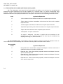
WARNING
ALL WARNINGS in this technical manual pertain to both the rifle and the carbines unless otherwise specified.
Before starting an inspection, be sure to clear the rifle. Do not pull the trigger until the rifle has been cleared. Inspect the
chamber to ensure that it is empty and no ammunition is in position to be chambered.
Do not keep live ammunition near work area.
To avoid injury to your eyes, use care when removing and installing spring-loaded parts.
All M1 6A2 rifles and M4 carbines must be inspected and gaged at least once annually for safety and serviceability. Initial
gaging is required 1 year from receipt of the weapons. Air Force users refer to inspection requirements in Air Force
Manual (AFM) 36-2227, Volume 1.
All Army Reserve and Army National Guard M16A2 rifles and M4 carbines must be inspected and gaged at least once
every 2 years, after the initial inspection/gaging procedures have been accomplished. This initial gaging procedure is
required 1 year from receipt of the weapons. This 2 year interval may be maintained unless preventive maintenance
checks and services (PMCS) or other physical evidence indicates that an individual unit’s M16A2 rifles and M4 carbines
require inspection/ gaging at a more frequent interval. If it is determined that a yearly inspection is necessary for an
individual unit, only that unit will be affected. This will not affect other units in regard to the interval of inspection.
It is recommended that training units inspect/gage all rifles and carbines at the end of each training cycle. Training units
will inspect/gage all rifles and carbines at least once annually.
Below direct support maintenance, DO NOT interchange bolt assemblies from one rifle/carbine to another. Doing so may
result in injury to, or death of, personnel.
Bolt cam pin must be installed or rifle/carbine will blow up while firing the first round. If the bolt cam pin is not installed,
injury to or death of, personnel may result.
Dry cleaning solvent is flammable and toxic and should be used in a well ventilated area. The use of rubber gloves is
necessary to protect the skin when washing rifle parts.
When using solid film lubricant or dichloromethane, be sure the area is well ventilated.
When using carbon removing compound (item 8, app D), avoid skin contact. If carbon removing compound comes In
contact with the skin, wash thoroughly with running water. using a good lanolin base cream after exposure to the
compound is helpful. Using gloves and protective equipment is required.
The lock plate prevents the selector lever from being placed in BURST and will be installed at the discretion of the unit
commander. It is mandatory for use in civil disturbance (riot control).
Only blank cartridge M200 is to be used when the blank firing attachment is attached to the rifle/carbine.
Change 5 a
ARMY TM 9-1005-319-23&P
AIR FORCE TO 11W3-5-5-42
WARNING (CONT)
Do not fire blank ammunition at a representative enemy at distances of less than 20 feet (6.10 Om). The unburned
propellant grains can cause injury within this distance.
For further information on safety, care, and handling of ammunition: Army and Air Force users refer to M16A2 Rifle
Operator’s Manual.
For additional first aid data, see Field Manual (FM) 21-11.
b
ARMY TM 9-1005-319-23&P
AIR FORCE TO 11W3-5-5-42
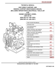
TECHNICAL MANUAL
ARMY NO. 9-1005-319-23&P
AIR FORCE TO 11W3-5-5-42
*ARMY TM 9-1005-319-23&P
AIR FORCE TO 11W3-5-5-42
DEPARTMENTS OF THE ARMY
AND AIR FORCE
Washington, DC, 1 May 1991
Unit and Direct Support Maintenance Manual
(Including Repair Parts and Special Tools List)
For
RIFLE, 5.56MM, M16A2, W/E
(1005-01-128-9936)
CARBINE, 5.56MM, M4
(1005-01-231-0973)
AND
CARBINE, 5.56MM, M4A1
(1005-01-382-0953)
Current as of December 1996
DISTRIBUTION STATEMENT. APPROVED FOR PUBLIC RELEASE; DISTRIBUTION IS UNLIMITED.
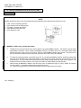
REPORTING ERRORS AND RECOMMENDING IMPROVEMENTS
You can help improve this manual. If you find any mistakes or if you know of a way to improve
the procedures please let us know.
Army users mail your letter, DA Form 2028 (recommended Changes to Publications and
Blank Forms), or DA Form 2028-2 located in the back of this manual direct to: Director,
Armament and Chemical Acquisition and Logistics Activity, ATTN: AMSTA-AC-NML, Rock
Island, IL 61299-7630.
Air Force users submit AFTO Form 22, Technical Order System Publication Improvement
Report and Reply, to: WR-ALC/MMDET, Robins AFB, GA 31098-5609.
A reply will be furnished to you.
CHAPTER
Section
Section
Section
HOW TO USE THIS MANUAL ..........................................................................
Page
iii
1 INTRODUCTION................................................................................................
External View of 5.56mm Rifle, M16A2..............................................................
External View of 5.56mm Carbine, M4...............................................................
External View of 5.56mm Carbine, M4A1 ..........................................................
Chapter Overview...............................................................................................
I General Information ...........................................................................................
II Equipment Description and Data........................................................................
III Principles of Operation .......................................................................................
1-1
1-0
1-0.1
1-0.1
1-1
1-1
1-3
1-6
*This manual supersedes ARMY TM 9-1005-319-23&P dated 28 August 1987, including all changes.
Change 5 i
ARMY TM 9-1005-319-23&P
AIR FORCE TO 11W3-5-5-42
CHAPTER
Section
Section
Section
Section
Section
Section
CHAPTER
Section
Section
Section
Section
CHAPTER
Section
APPENDIX
APPENDIX
APPENDIX
Section
Section
Group
Group
Group
Group
Group
ii Change 4
2
I
II
III
IV
V
VI
3
I
II
III
IV
4
Page
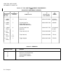
UNIT MAINTENANCE INSTRUCTIONS................................................... 2-1
Chapter Overview ...................................................................................... 2-1
Repair Parts, Special Tools, TMDE, and Support Equipment ................... 2-1
Service Upon Receipt ................................................................................ 2-1
Preventive Maintenance Checks and Services (PMCS) ........................... 2-3
Troubleshooting ......................................................................................... 2-20
Maintenance Procedures........................................................................... 2-33
Preparation for Storage or Shipment......................................................... 2-70
Illus
Figure
DIRECT SUPPORT MAINTENANCE INSTRUCTIONS ........................... 3-1
Chapter Overview ...................................................................................... 3-1
Repair Parts, Special Tools, TMDE, and Support Equipment ................... 3-1
Troubleshooting ......................................................................................... 3-2
Maintenance Procedures for the M16A2 Rifle, M4 and M4A1 Carbine..... 3-15
Preembarkation Inspection of Materiel in Units Alerted for Overseas
Movement (A.F. Only)................................................................................ 3-95
I
MAINTENANCE OF AUXILIARY EQUIPMENT .......................................
Chapter Overview ......................................................................................
Auxiliary Equipment Repair .......................................................................
A.
B.
REFERENCES ..........................................................................................
MAINTENANCE ALLOCATION CHART..................................................
C.
I
II
00
00.1
00.101
01
0101
0102
02
03
0301
0301
0302
030201
030202
04
0401
0401A
0402
0403
040301
0404
0404A
REPAIR PARTS AND SPECIAL TOOLS LIST.........................................
Introduction ................................................................................................
Repair Parts List ........................................................................................
5.56MM Rifle, M16A2, Carbine, M4 and M4A1 .........................................
M4 and M4A1 Carrying Handle Assembly.................................................
M4 and M4A1 Rear Sight Assembly..........................................................
Bolt carrier assembly .................................................................................
Bolt assembly ............................................................................................
Key and bolt carrier assembly ...................................................................
Handle assembly .......................................................................................
Upper receiver and barrel assembly..........................................................
Barrel assembly, M16A2............................................................................
Replacement Barrel & Front Sight Assembly, M4/M4A1...........................
Upper receiver assembly ...........................................................................
Forward assist assembly ...........................................................................
Rear sight assembly, M16A2.....................................................................
Lower receiver and buttstock assembly ....................................................
Buttstock assembly, M16A2 ......................................................................
Buttstock assembly, M4/M4A1 ..................................................................
Hammer assembly.....................................................................................
Trigger assembly .......................................................................................
Trigger subassembly,M16A2 and M4........................................................
Lower receiver and receiver extension assembly, M16A2 ........................
Lower receiver and receiver extension assembly, M4 and M4A1 .............
4-1
4-1
4-1
A-1
B-1
C-1
C-1
C-1-1
C-1-1
C-1A-1
C-1B-1
C-2-1
C-3-1
C-4-1
C-5-1
C-6-1
C-7-1
C-7-1
C-8-1
C-9-1
C-10-1
C-11-1
C-12-1
C12A-1
C-13-1
C-14-1
C-15-1
C-16-1
C16A-1
C-1
C-1A
C-1B
C-2
C-3
C-4
C-5
C-6
C-7
C-7
C-8
C-9
C-10
C-11
C-12
C12A
C-13
C-14
C-15
C-16
C16A
ARMY TM 9-1005-319-23&P
AIR FORCE TO 11W3-5-5-42
Page
APPENDIX
Section
Section
APPENDIX
APPENDIX
C. REPAIR PARTS AND SPECIAL TOOLS LIST--Cont.
III Special Tools List....................................................................................... C-17-1
IV
National Stock Number and Part Number Index ....................................... I-1
D.
E.
Illus
Figure
C-17
EXPENDABLE/DURABLE SUPPLIES AND MATERIALS LIST.............. D-1
ILLUSTRATED LIST OF MANUFACTURED ITEMS ............................... E-1
ALPHABETICAL INDEX........................................................................... Index-1
Change 4 ii.1/(ii.2 blank)
ARMY TM 9-1005-319-23&P
AIR FORCE TO 11W3-5-5-42
HOW TO USE THIS MANUAL
Read this manual carefully before performing required maintenance. This manual will be referred to for
Inspection/Maintenance and Repair procedures.
GENERAL
There are several things you need to know to use this manual efficiently.
1. All references in the manual are to pages only. Reference to maintenance procedures is to the page where the
respective initial setup appears.
2. Illustrations for the maintenance procedures show only those parts affected by the operation being performed.
3. Whenever the male gender is mentioned in the manual (i.e., crewman, repairman), it also pertains to females.
4. When the term “evacuate to support maintenance” is used, the entire rifle must be evacuated.
5. When a procedure is common to M16A2 rifle, and M4/M4A1 carbine, ONLY the M16A2 configuration will be
depicted. If a procedure is not common to both weapons, the procedure will be incorporated.
6. When the word rifle is referenced in text, it will reference the rifle and the carbines.
INDEXES
This manual is organized to help you find the information you need quickly. There are several useful indexes.
1. Table of Contents. Lists in order all chapters, sections, and appendixes. Gives page references.
2. Nomenclature Cross-References List.
3. Chapter Overviews. Summarize material covered in the chapter. Are located at the beginning of each chapter.
4. Symptom Index. Located just before the troubleshooting table in each maintenance chapter. Lists, in alphabetical
order, parts of the rifle with possible malfunctions. References pages of the troubleshooting table.
5. Alphabetical Index. Located at the end of the manual. An extensive subject index for everything in the manual.
Gives page references.
MAINTENANCE PROCEDURES
There are two maintenance chapters:
Army personnel use chapter two for unit maintenance procedures and chapter three for direct support maintenance
procedures.
Change 4 iii
ARMY TM 9-1005-319-23&P
AIR FORCE TO 11 W3-5-5-42
Air Force personnel: Only Air Force Specialty Code 753XX Combat Arms Training and Maintenance (CATM) specialists,
technicians, and gunsmiths are authorized to perform maintenance procedures contained in this manual.
Each maintenance task has an initial setup containing a list of the following things you will need in order to do your
maintenance task.
1. Tools and Special Tools. For standard and special tools, see appendixes B and C. Army users are to use the Tool
Set, Gage Set, and/or Shop Set listed in the initial setup.
2. Materials/Parts. Lists expendable materials and 100 percent replaceable parts. Each material or part is followed by
a part number or appendix reference.
3. References. Lists other publications containing necessary information.
4. Equipment Condition. Lists conditions to be met before starting the procedure. The reference on the left of the
condition is a page reference to instructions for setting up the condition.
5. General Safety Instructions. Lists safety instructions to follow before performing maintenance procedures.
iv/(v blank) Change 3
ARMY TM 9-1005-319-23&P
AIR FORCE TO 11 W3-5-5-42
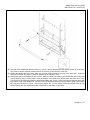
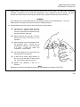
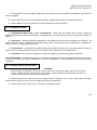
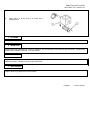
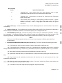
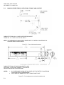
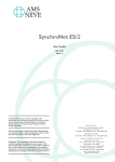
EXTERNAL VIEW OF 5.56 MM RIFLE M16A2
1-0
ARMY TM 9-1005-319-23&P
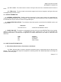
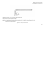
AIR FORCE TO 11W3-5-5-42
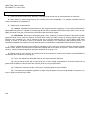
EXTERNAL VIEW OF 5.56MM CARBINE, M4/M4A1
Change 4 1-0.1/(1-0.2 blank)
ARMY TM 9-1005-319-23&P
AIR FORCE TO 11W3-5-5-42
CHAPTER 1
INTRODUCTION
CHAPTER OVERVIEW
This chapter contains general information, equipment description and data, and principles of operation for the M16A2 rifle
and M4/M4A1 carbines.
Section I. GENERAL INFORMATION
1-1.
SCOPE.
a. Type of Manual: Unit and Direct Support Maintenance.
b. Model Number and Equipment Name: 5.56mm Rifle M16A2, M4 and M4A1 Carbines.
c. Purpose of Equipment. Provides personnel an offensive/defensive capability to engage targets with small arms fire.
1-2.
MAINTENANCE FORMS, RECORDS, AND REPORTS. Department of the Army forms and procedures used for
equipment maintenance will be those prescribed by DA PAM 738-750, The Army Maintenance Management System.
Air Force users refer to TO 11W-1-10 for applicable forms and records.
1-3.
DESTRUCTION OF ARMY MATERIEL TO PREVENT ENEMY USE. See TM 750-244-7.
1-4.
PREPARATION FOR STORAGE OR SHIPMENT. Refer to page 2-70.
Air Force users refer to Special Package Instruction (SPI) 00-856-6885.
1-5.
OFFICIAL NOMENCLATURE, NAMES AND DESIGNATIONS.
NOMENCLATURE CROSS-REFERENCE LIST
Common Name
Official Nomenclature
Action Spring ...................................................................
Ball Bearing .....................................................................
Bolt Catch Spring.............................................................
Bolt Carrier Key Tool .......................................................
Burst Disconnector ..........................................................
Cam Clutch Spring ..........................................................
Carbine ............................................................................
Charging Handle Assembly.............................................
Compression Helical Spring
Bearing Ball
Compression Helical Spring
Machine Key
Lock-Release Lever
Helical Spring
M4/M4A1 Carbine
Handle Assembly
Change 5 1-1
ARMY TM 9-1005-319-23&P
AIR FORCE TO 11 W3-5-5-42
1-5.
OFFICIAL NOMENCLATURE, NAMES AND DESIGNATIONS (CONT).
NOMENCLATURE CROSS-REFERENCE LIST
Common Name
Official Nomenclature
Disconnector Springs ......................................................
Ejector Spring ..................................................................
Extractor Spring Assembly ..............................................
Hammer Spring ...............................................................
Lower Receiver Extension...............................................
Magazine .........................................................................
Magazine Catch Spring ...................................................
Peel Washer ....................................................................
Pistol Grip ........................................................................
Pivot Pin Detent...............................................................
Rifle .................................................................................
Rifle Barrel Assembly ......................................................
Selector Lever .................................................................
Semiautomatic Disconnector...........................................
Sling.................................................................................
Trigger Spring..................................................................
Upper Receiver................................................................
Compression Helical Spring
Helical Spring
Spring Assembly
Torsion Helical Spring
Spring Receiver Holder
Cartridge Magazine
Compression Helical Spring
Shim
Rifle Grip
Takedown Pin Detent
Rifle, 5.56mm, M16A2
Barrel Assembly
Fire Control Selector
Lock-Release Lever
Small Arms Sling
Torsion Helical Spring
Upper Cartridge Receiver
1-6.
REPORTING EQUIPMENT IMPROVEMENT RECOMMENDATIONS (EIR).
If your M16A2 rifle needs
improvement, let us know. Send us an EIR. You, the user, are the only one who can tell us what you don’t like about your
equipment. Let us know why you don’t like the design.
Army users submit SF 368 (Product Quality Deficiency Report) to: Commander, U.S. Army Armament Research,
Development and Engineering Center, ATTN: AMSTA-AR-QAW (R)/Customer Feedback Center, Rock Island, IL 612997300.
Air Force users submit Materiel Deficiency Report (MDR) to: DIR MAT MGT ROBINS AFB GA//MMIBTC// and Product
Quality Deficiency Report to: DIR MAT MGT ROBINS AFB GA//MMQA// IAW Technical Order 00-35D-54.
A reply will be sent to you.
1-7.
CORROSION PREVENTION AND CONTROL (CPC). CPC of Army materiel is a continuing concern. It is
important that any corrosion problems with this item be reported so that the problem can be corrected and improvements
can be made to prevent the problem in future items,
While corrosion is typically associated with rusting of metals, it can also include deterioration of other materials such as
rubber and plastic. Unusual cracking, softening, swelling, or breaking of these materials may be a corrosion problem.
1-2 Change 4
ARMY TM 9-1005-319-23&P
AIR FORCE TO 11W3-5-5-42
If a corrosion problem is identified, it can be reported using Standard Form 368, Product Quality Deficiency Report. Use of
key words such as "corrosion", "rust", " deterioration", or "cracking" will assure that the information is identified as a CPC
problem.
Army users submit Product Quality Deficiency Report (SF 368) to:
Commander
U.S. Army Armament Research, Development and Engineering Center
ATTN: AMSTA-AR-QAW (R)
Rock Island, IL 61299-7300
Air Force users submit Materiel Deficiency Report (MDR) to:
DIR MAT MGT
ATTN: MMIBTC
Robins AFB, GA
and Product Quality Deficiency Report to:
DIR MAT MGT
ATTN: MMQA
Robins AFB, GA
Section II. EQUIPMENT DESCRIPTION AND DATA
1-8.
EQUIPMENT CHARACTERISTICS, CAPABILITIES, AND FEATURES.
a. Characteristics.
(1) Light weight
(2) Air-cooled
(3) Gas-operated
(4) Magazine-fed
(5) Semiautomatic or burst fire
b. Capabilities. Provides personnel an offensive/defensive capability to engage targets with direct small arms fire.
c. Features.
(1) Receivers are made of light-weight aluminum alloys; however, the safety , durability, and function of the rifles
are in no way reduced. The portability and logistical values are greatly increased, particularly when air transport is used.
(2) The bolt locking action is one of the mechanical features of the rifle. The bolt assembly and barrel extension
contain locking lugs which engage and lock the bolt assembly firmly in the barrel extension. The initial force of the
explosion of the cartridge is absorbed by the barrel, barrel extension, and bolt assembly.
Change 4 1-3
ARMY TM 9-1005-319-23&P
AIR FORCE TO 1 1W3-5-5-42
1-8.
EQUIPMENT CHARACTERISTICS, CAPABILITIES, AND FEATURES (CONT).
(3) The trigger guard is easily adaptable to winter operations. A spring-loaded retaining pin is depressed to allow
ready access to the trigger when wearing arctic mittens.
(4) The ejection port cover prevents dirt or sand from getting into the ejection port. The ejection port cover must
be closed during periods when firing is not anticipated. It opens automatically by the forward or rearward movement of the
bolt carrier assembly.
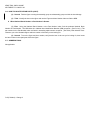
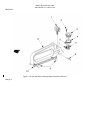
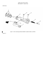
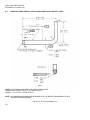
1-9.
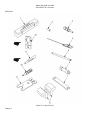
LOCATION AND DESCRIPTION OF MAJOR COMPONENTS.
(A) MAGAZINE. 30 cartridge capacity.
(B) SLING. The sling is adjustable and provides a means to carry the weapon.
(C) BOLT CARRIER ASSEMBLY. Carries bolt assembly to chamber and fires the weapon. Contains the firing pin,
cartridge extractor, bolt assembly, cartridge ejector, and bolt cam pin.
(D) CHARGING HANDLE ASSEMBLY. Provides a means of charging the weapon.
(E) M16A2 UPPER RECEIVER AND BARREL ASSEMBLY. Upper receiver contains rear sight assembly, ejection
port, ejection port cover, and a housing for the key and bolt carrier assembly and bolt assembly. Rifle barrel
assembly is air-cooled, contains compensator and front sight assembly, and holds the two handguard assemblies
and the sling swivel.
(F) LOWER RECEIVER AND BUTTSTOCK ASSEMBLY. Lower receiver contains the trigger assembly, sear,
hammer assembly, selector lever, rifle grip, bolt catch, and buttstock assembly. The buttstock assembly houses
the action spring, buffer assembly, and extension assembly.
(G) M4/M4A1 CARRYING HANDLE. Provides a means of carrying carbine.
(H) M4/M4A1 UPPER RECEIVER AND BARREL ASSEMBLY. Upper receiver contains, ejection port, ejection port
cover, a housing for key and bolt carrier assembly and bolt assembly, and mounting surface for the carrying
handle assembly. Carbine barrel assembly is air-cooled, contains compensator and front sight assembly, and
holds the two handguard assemblies and the sling swivel.
1-4 Change 4
ARMY TM 9-1005-319-23&P
AIR FORCE TO 11W3-5-5-42
Change 4 1-4.1
ARMY TM 9-1005-319-23&P
AIR FORCE TO 11W3-5-5-42
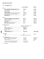
1-10.
EQUIPMENT DATA.
US CUSTOMARY
METRIC
Weight:
Carbine, M4/M4A1 without magazine and sling ......
Rifle, Ml 6A2 without magazine and sling................
Sling, adjustable ......................................................
Empty magazine ......................................................
Loaded magazine ....................................................
Carbine, M4/M4A1 w/sling and loaded magazine ...
Rifle M16A2 w/sling and loaded magazine..............
Bayonet-Knife M7 ....................................................
Scabbard M10 o ......................................................
6 lb 7 oz
7 lb 8 oz
4 oz
4 oz
1 lb 1 oz
7 lb 12 oz
8 lb 13 oz
10.5 oz
5 oz
2.91 kg
3.40 kg
0.11 kg
0.11 kg
0.48 kg
3.51 kg
4.00 kg
0.30 kg
0.14 kg
Length:
Carbine with compensator, buttstock extended.......
Carbine with compensator, buttstock closed ...........
Rifle with compensator ............................................
Barrel (Carbine) .......................................................
Barrel (Rifle).............................................................
Barrel with compensator (Carbine) ..........................
Barrel with compensator (Rifle) ...............................
33.0 in
29.75 in
39.63 in
14.5 in
20 in
15.5 in
21 in
83.82 cm
75.57 cm
100.66 cm
36.83 cm
50.8 cm
39.37 cm
53.34 cm
Mechanical features:
Rifling....................................................................... right-hand twist 6 grooves, 1 turn
................................................................................. in 7 inches (17.78 cm)
Method of operation.................................................
direct gas
Type of breech mechanism .....................................
rotating bolt
Method of feeding ....................................................
magazine
Cooling.....................................................................
air
Trigger pull (M16A2 & M4).......................................
5.5 to 9.5 lb
Trigger pull (M4A1) ..................................................
5.5 to 8.5 lb
Ammunition:
Caliber .....................................................................
223
Type......................................................................... ball, blank, dummy, and tracer
Firing characteristics:
Muzzle velocity (Carbine) (approximate) .................
Muzzle velocity (Rifle) (approximate).......................
Chamber pressure ...................................................
Cyclic rate of fire (Carbine) (approximate)...............
Cyclic rate of fire (Rifle) (approximate) ....................
1-4.2 Change 5
2,970 fps
3,100 fps
52,000 psi
700-970 rds/m
700-900 rds/m
2.49 to 4.31kg
2.49 to 3.86 kg
5.56mm
905.85 mps
945.5 mps
358,540
kPa
ARMY TM 9-1005-319-23&P
AIR FORCE TO 11W3-5-5-42
1-10.
EQUIPMENT DATA (CONT).
US CUSTOMARY
Maximum rate of fire:
Semiautomatic .........................................................
Burst ........................................................................
Sustained rate of fire ...............................................
Maximum range .......................................................
45 rds/m
90 rds/m
12/15 rds/m
3,938 yards
Maximum effective range:
Individual/point targets (Carbine).............................
Individual/point targets (Rifle) ..................................
Area targets (Carbine) .............................................
Area targets (Rifle) ..................................................
547 yards
602 yards
650 yards
875 yards
METRIC
Approximately
3,600 meters
500 meters
550 meters
600 meters
800 meters
Section III. PRINCIPLES OF OPERATION
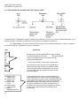
1-11.
GENERAL.
The 5.56mm M16A2 and M4/M4A1 carbine:
a. Is gas-operated. It fires in either the semiautomatic or burst mode.
b. Has positive locking of the bolt. Firing pin is part of the bolt carrier assembly and cannot strike the primer until
the bolt assembly is fully locked.
Change 4 1-5
ARMY TM 9-1005-319-23&P
AIR FORCE TO 11W3-5-5-42
Section III. PRINCIPLES OF OPERATION (CONT).
1-12.
PRINCIPLES OF OPERATION.
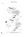
(A) MAGAZINE. Holds cartridges ready for feeding and provides a guide for positioning cartridges for stripping.
Provides quick reload capabilities for sustained firing.
(B) SLING. Provides the means for carrying the weapon.
(C) BOLT CARRIER ASSEMBLY. Provides stripping, chambering, locking, firing, extraction, and ejection of
cartridges using the drive springs and projectile propelling gases for power.
(D) CHARGING HANDLE ASSEMBLY. Provides initial charging of the weapon. The handle latch locks the
charging handle assembly in the forward position during sustained fire to prevent injury to the operator.
(E) M16A2 UPPER RECEIVER AND BARREL ASSEMBLY. Provides support for the bolt carrier assembly.
The barrel chambers the cartridge for firing and directs the projectile.
(F) LOWER RECEIVER AND BUTTSTOCK ASSEMBLY. Provides firing control for the rifle and carbine.
M16A2 ONLY provides storage for basic cleaning materials.
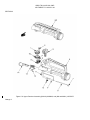
(G) M4/M4A1 CARRYING HANDLE ASSEMBLY. Provides a means of carrying the carbine, contains rear
sight assembly, and can be removed for mounting various optics.
(H) M4/M4A1 UPPER RECEIVER AND BARREL ASSEMBLY. Provides support for the bolt carrier assembly.
The barrel chambers the cartridge for firing and directs the projectile.
1-6 Change 5
ARMY TM 9-1005-319-23&P
AIR FORCE TO 11W3-5-5-42
CHAPTER 2
UNIT MAINTENANCE INSTRUCTIONS
CHAPTER OVERVIEW
This chapter provides information and Instructions to help keep the rifle in good repair and contains the following sections:
a.
b.
c.
d.
e.
Repair Parts, Special Tools, TMDE, and Support Equipment
Service Upon Receipt
Preventive Maintenance Checks and Services (PMCS)
Troubleshooting
Maintenance Procedures
Section I. REPAIR PARTS, SPECIAL TOOLS, TMDE,
AND SUPPORT EQUIPMENT
2-1.
COMMON TOOLS AND EQUIPMENT. For authorized common tools and equipment, refer to the Modified Table
of Organization and Equipment (MTOE) applicable to your unit.
Air Force users must maintain the following common tools:
3-ounce soft-brass hammer
Vise
Flat tip screwdriver
Punch
Tweezers/round nose pliers
Hammer
Needle nose pliers
2-2. SPECIAL TOOLS, TMDE, AND SUPPORT EQUIPMENT. Special tools required for unit
support are listed in appendixes B and C. Fabricated tools are listed and illustrated in appendix E.
2-3. REPAIR PARTS. Repair parts are listed and illustrated in appendix C of this manual.
Section II. SERVICE UPON RECEIPT
2-4.
GENERAL.
a. Inspect the rifle for damage Incurred during shipment. If rifle has been damaged, report the damage on SF 364,
Report of Discrepancy (ROD).
b. Check the rifle against the packing slip to see If shipment is complete. Army users report all discrepancies in
accordance with DA PAM 738-750.
Air Force users submit Materiel Deficiency Report (MDR) to: DIR MAT MGT ROBINS AFB
GA//MMIBTC// and Product Quality Deficiency Report to: DIR MAT MGT ROBINS AFB
GA//MMQA//. IAW Technical Order 00-35D-54.
c. Check to see whether the equipment has been modified.
2-1
ARMY TM 9-1005-319-23&P
AIR FORCE TO 11W3-5-5-42
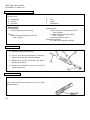
2-5.
SERVICE UPON RECEIPT OF MATERIEL.
WARNING
Before starting an inspection, be sure to clear the rifle. Do not actuate the trigger before clearing the rifle.
Inspect the chamber to make sure it is empty and free of obstructions. Check to see there are no
obstructions in the barrel and no ammunition is in position to be chambered.
SERVICE UPON RECEIPT
LOCATION
1. Container
ITEM
a. M16A2 rifle or
M4/M4A1 carbine
b. Basic issue
items
2. M16A2
rifle or
M4/M4A1
carbine
2-2 Change 4
ACTION
REMARKS
a. Remove rifle from containers.
b. Inspect the equipment for damage incurred during shipment
If the equipment has
been damaged, report
the damage on SF
Form 364, Report of
Discrepancy (ROD).
c. Check the equipment against
the packing list to see if the
shipment is complete
Report all discrepancies in accordance
with the instructions of
DA PAM 738-750.
Check for missing items
Refer to TM 9-1005319-10 (operator’s
manual).
a. Barrel assembly If volatile corrosion inhibitor (VCI)
is in barrel, remove and discard.
b. All parts
a. Field-strip rifle and inspect for
missing, damaged, and rusted
or corroded parts.
Refer to operator’s
manual.
b. Clean and lubricate
Refer to operator’s
manual.
c. Reassemble
Refer to operator’s
manual.
d. Function check
Refer to page 2-69.
ARMY TM 9-1005-319-23&P
AIR FORCE TO 11W3-5-5-42
SERVICE UPON RECEIPT (CONT)
LOCATION
ITEM
c. Magazine
ACTION
REMARKS
e. Check to see whether the equipment has
been modified
Refer to DA PAM
25-30.
Check for positive retention and functioning of bolt
catch
Refer to operator’s
manual.
Section III. PREVENTIVE MAINTENANCE CHECKS AND SERVICES (PMCS)
2-6. GENERAL This section contains the procedures and instructions necessary to perform unit preventive maintenance
checks and services. These services are to be performed by unit maintenance personnel with the assistance of the
operator where practical.
2-7. PREVENTIVE MAINTENANCE CHECKS AND SERVICES
WARNING
Before starting an inspection, be sure to clear the rifle. Do not keep live ammunition near the work area.
a. General. The PMCS procedures are contained in the table following. They are arranged in logical sequence
requiring a minimum amount of time and motion on the part of the persons performing them and are arranged so that
there will be minimum interference between persons performing checks simultaneously on the same end item.
b. Item No. Column. Checks and services are numbered in disassembly sequence. This column shall be used as a
source of item numbers for the "TM Number" column on DA Form 2404, Equipment Inspection and Maintenance
Worksheet, in recording results of PMCS.
c. Interval Column. This column gives the designated interval when each check is to be performed.
d. Item To Be Checked Or Serviced Column. This column lists the items to be checked or serviced.
e. Procedure Column. This column contains a brief description of the procedure by which the check is to be
performed. It contains all the information required to accomplish the checks and services. Information marked SH
Indicates a specific equipment shortcoming and the procedure needed to correct the shortcoming.
NOTE
For the purpose of this technical manual, the following definition is supplied. This definition is not intended
to apply to any other document
Shortcoming (SH): A fault that requires maintenance or supply action on a piece of equipment, but does
not render equipment Not Mission Capable
f. Not Fully Mission Capable If: Column. This column contains a brief statement of the condition (e.g.,
malfunction, shortage) that would cause the covered equipment to be less than fully ready to perform its assigned mission.
Change 3 2-3
ARMY TM 9-1005-319-23&P
AIR FORCE TO 11W3-5-5-42
2-7.
PREVENTION MAINTENANCE CHECKS AND SERVICES (CONT).
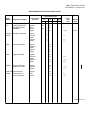
PREVENTIVE MAINTENANCE CHECKS AND SERVICES FOR M16A2 RIFLE (CONT)
Item
No.
Interval
Item to be
Checked or
Serviced
Procedure
Not Fully Mission
Capable if:
WARNING
Before starting an inspection, be sure to clear the weapon. Do not pull the trigger until the weapon has
been cleared. Inspect the chamber to ensure that it is empty and no ammunition is in position to be
chambered. Do not keep live ammunition near work area.
NOTE
An inactive weapon is a weapon which has been stored in an arms room for a period of 90 days without
use. The weapon may or may not have been assigned to an individual.
Inactive weapons shall receive quarterly PMCS unless inspection reveals more frequent servicing is
necessary.
Normal cleaning (PMCS) of an inactive weapon will be performed every 90 days. Should the unit armorer
detect corrosion on a weapon prior to the end of the 90-day period, the PMCS should be performed
immediately.
Solid Film Lubricant (SFL) is the authorized touch up for the M16A2 Rifle and M4/M4A1 Carbine and may
be used on up to one third of the exterior finish of the weapon.
FOR ARMY CONUS USE ONLY AND AIR FORCE TRAINING WEAPONS ONLY: Solid Film Lubricant
may be used as a touch up without limitation on the upper receiver and barrel assembly. This is to say that
units which DO NOT fall under the category of Divisional Combat Units or rapid deployment type units
may have up to 100 percent of the exterior surface of the upper receiver and barrel assembly protected
with SFL.. Prior to application of SFL, the surface must be thoroughly cleaned and inspected for corrosion
and/or damage. If corroded or damaged, the part must be repaired or replaced prior to application of SFL.
Continued use under combat conditions would result in an unprotected surface when the SFL wears off.
This would result in a large light reflecting surface and accelerated deterioration of the unprotected
surface. Therefore, Divisional Combat Units and units which fall under the definition of Rapid Deployment
type must adhere to the limitation of NOT over one third of their exterior surface covered by SFL.
When determining mission capability, deadline if it is a deficiency.
2-4 Change 4
ARMY TM 9-1005-319-23&P
AIR FORCE TO 11W3-5-5-42
PREVENTIVE MAINTENANCE CHECKS AND SERVICES FOR M16A2 RIFLE (CONT)
Item
No.
Interval
Item to be
Checked or
Serviced
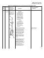
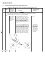
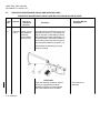
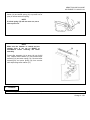
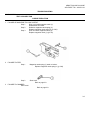
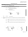
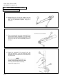
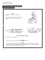
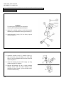
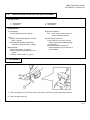
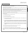
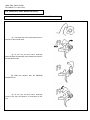
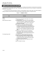
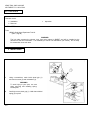
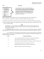
1
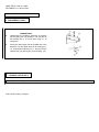
Quarterly Magazine
(serviceability
check)
Procedure
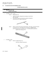
Disassemble as In TM 91005-319-10 (operator’s
manual). Inspect tube (1)
for bulges, dents, or damaged feeder lips (2). Inspect
spring (3) and follower (4)
for kinks or damage. SHReplace the magazine if any
of these conditions exist.
Reassemble magazine and
check for binding during
operation of follower (4).
SH-Replace the magazine
if the follower binds.
2
Quarterly Charging handle
assembly and
selector lever
WARNING
If the rifle falls any
of the following
selector lever tests,
evacuate It to support maintenance.
Continued use of the
rifle could result In
injury to, or death
of, personnel.
2-5
Not Fully Mission
Capable if:
A magazine is
not available fu;
use with the
rifle.
ARMY TM 9-1005-319-23&P
AIR FORCE TO 11W3-5-5-42
2-7.
PREVENTIVE MAINTENANCE CHECKS AND SERVICES (CONT).
PREVENTIVE MAINTENANCE CHECKS AND SERVICES FOR M16A2 RIFLE (CONT)
Item
No.
Interval
Item to be
Checked or
Serviced
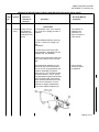
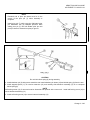
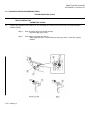
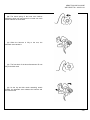
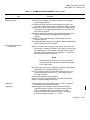
2
Quarterly Charging handle
(cont)
assembly and
selector lever
(cont)
Procedure
Not Fully Mission
Capable if:
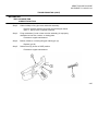
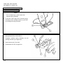
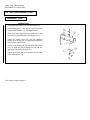
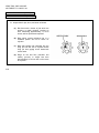
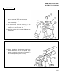
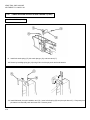
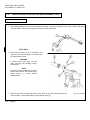
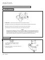
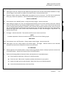
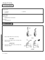
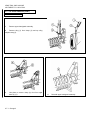
Pull charging handle (1) to rear. Check
that chamber is clear. Let bolt carrier
assembly (2) close. Leave hammer in
cocked position. Do not pull trigger
Charging handle
does not lock in
place when in the
forward position.
Place selector lever (3) in SAFE position
Pull trigger. Place selector lever (3) in
SEMI position.
Hammer falls.
NOTE
For the purpose of the
following test, "SLOW" is
defined as 1/4 to 1/2 the
normal rate of trigger
release.
2-6 Change 4
Pull trigger
Hammer does not
fall.
Hold trigger to the rear, charge
weapon, and release the trigger with
a slow, smooth motion, without hesitations or stops, until the trigger is
fully forward (an audible click should
be heard).
Hammer falls.
Repeat the above SEMI position test
five times
The weapon malfunctions during
any of these five
tests.
ARMY TM 9-1005-319-23&P
AIR FORCE TO 11W3-5-5-42
PREVENTIVE MAINTENANCE CHECKS AND SERVICES FOR M16A2 RIFLE (CONT)
Item
No.
Interval
Item to be
Checked or
Serviced
2
Quarterly Charging handle
(cont)
assembly and
selector lever
(cont)
Procedure
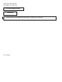
M16A2 and M4 ONLY
Place selector lever (3) in BURST
position. Charge weapon and squeeze
trigger.
Hold trigger to the rear, pull the charging
handle to the rear and release it three
times. Release trigger. Squeeze trigger.
Not Fully Mission
Capable if:
Hammer does not
fall.
Hammer does not
fall.
NOTE
The burst disconnector should
have held the hammer to the
rear when it engaged the deep
notch of the burst cam.
M4A1 ONLY
Place selector lever (3) in AUTO position
Charge carbine and squeeze trigger
Hammer should fall.
Hold trigger to the rear, charge carbine,
and release trigger. Squeeze trigger.
Hammer should not fall.
Hammer does not
fall.
Hammer falls.
2-7 Change 4
ARMY TM 9-1005-319-23&P
AIR FORCE TO 11W3-5-5-42
2-7.
PREVENTIVE MAINTENANCE CHECKS AND SERVICES (CONT).
PREVENTIVE MAINTENANCE CHECKS AND SERVICES FOR M16A2 RIFLE (CONT)
Item
No.
Interval
Item to be
Checked or
Serviced
2
Quarterly Charging handle
(cont)
assembly and
selector lever
(cont)
Procedure
NOTE
Automatic sear should have
released hammer while holding
trigger in the squeezed position
before releasing and resqueezing the trigger.
All weapons
With hammer in forward position, using
moderate finger/thumb pressure attempt
to place the selector lever (3) in SAFE
position
2-7.1/(2-7.2 blank) Change 4
Not Fully Mission
Capable if:
Moderate finger/
thumb pressure
moves selector
lever to SAFE position.
ARMY TM 9-1005-319-23&P
AIR FORCE TO 11W3-5-5-42
2-7.
PREVENTIVE MAINTENANCE CHECKS AND SERVICES (CONT).
PREVENTIVE MAINTENANCE CHECKS AND SERVICES FOR M16A2 RIFLE (CONT)
Item
No.
Interval
Item to be
Checked or
Serviced
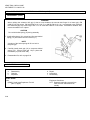
3
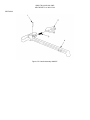
Quarterly Upper receiver
and barrel assembly (handguard assemblies)
Procedure
Not Fully Mission
Capable if:
CAUTION
Do not use screwdriver or any other
tool when removing
the handguard assemblies, doing so
may damage the
handguard assemblies and/or slip.
NOTE
Refer to operator’s
manual for "buddy
system" procedure
on removing handguard assemblies.
Remove and Inspect handguard assemblies (1) internally and externally for cracks
and/or damage. Cracks are
acceptable providing they
do not extend into the
handguard retaining flange,
or adversely affect rifle
operation or operator safety
or proper retention of handguard assembly. Discard
and replace the handguard
assembly (1) If the heatshield is loose enough to
rattle when Installed on rifle.
2-8
Handguard missing or unserviceable.
ARMY TM 9-1005-319-23&P
AIR FORCE TO 11W3-5-5 42
PREVENTIVE MAINTENANCE CHECKS AND SERVICES FOR M16A2 RIFLE (CONT)
Item
No.
Interval
Item to be
Checked or
Serviced
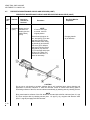
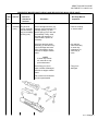
4
Quarterly Upper receiver
and barrel assembly (serviceability check)
Procedure
Not Fully Mission
Capable if:
WARNING
Dry cleaning solvent
is flammable and
toxic and should be
used in a well ventilated area The use
of rubber gloves is
necessary to protect
the skin when washing rifle parts
CAUTION
Damage may occur
if excessive force is
used to release takedown pin or pivot
pin. Use hand pressure ONLY.
Release takedown pins and
open and separate receivers
Hand check compensator
(1) for looseness on barrel
(2), then hand check barrel
(2) for looseness on upper
receiver (3). Check center
slot of compensator for
alignment (p 2-50). If compensator or barrel is loose,
evacuate to support maintenance
Compensator or
barrel is loose
Check gas tube (4), forward
assist assembly (5), and
rear sight assembly (6) for
damage, The rear sight
spring should retain the rear
sight assembly (6) In either
position with firmness
SH - If damaged, evacuate
to support maintenance.
2-9
ARMY TM 9-1005-319-23&P
AIR FORCE TO 11W3-5-5-42
2-7.
PREVENTIVE MAINTENANCE CHECKS AND SERVICES (CONT).
PREVENTIVE MAINTENANCE CHECKS AND SERVICES FOR M16A2 RIFLE (CONT)
Item
No.
Interval
Item to be
Checked or
Serviced
4
Quarterly Upper receiver
(cont)
and barrel as
sembly (service
ability check)
(cont)
Procedure
Not Fully Mission
Capable if:
NOTE
If front or rear sight
is moved, return to
original position
Check front sight post, de
tent, and spring (7) for dam
age and corrosion Clean
and lubricate Check charg
ing handle (8) and election
port cover (9) for defects
and proper function Check
sling swivel (10) and rivet
(11) for damage and proper
function SH Other corn
ponents are defective, re
place as necessary.
Charging handle
(8) is defective.
CAUTION
Do not use a wire brush to roughen surfaces Use a well ventilated area during cleaning and
application of solid film lubricant. If solid film lubricant comes in contact with moving parts or
functioning surfaces of the rifle, remove lubricant immediately by washing with dry cleaning solvent.
NOTE
Shiny metal exterior surfaces of the rifle should be recoated with solid film lubricant (Item 21, app
D). Clean surface with dry cleaning solvent (item 16, app D); dry, roughen with abrasive cloth
(Item 13, app D) and apply solid film lubricant.
2-10
ARMY TM 9-1005-319-23&P
AIR FORCE TO 11W3-5-5-42
PREVENTIVE MAINTENANCE CHECKS AND SERVICES FOR M16A2 RIFLE (CONT)
Item
No.
Interval
Item to be
Checked or
Serviced
4
Quarterly Upper receiver
(cont)
and barrel
assembly
(serviceability
check) (cont)
Procedure
Not Fully Mission
Capable if:
Inspect upper receiver (3)
finish for scratches or worn
shiny spots.
If scratched or worn shiny in
spots, disassemble and remove all lubricant from surface with dry cleaning solvent (item 16, app D). Wear
rubber gloves (item 18, app
D) and use a wash pan (item
24, app D) to apply solvent.
Let parts dry thoroughly.
Roughen the surface using
abrasive cloth (item 1 3, app
D) and apply solid film lubricant (item 16, app D). Allow
16 to 24 hours to dry before
handling.
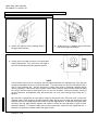
Hold barrel (2) at 40-degree
angle (muzzle down). Pull
charging handle (8) to rear.
Hold bolt carrier assembly
(12) to rear and push charging handle forward. Release
bolt carrier assembly (12).
The bolt carrier assembly
should close and lock under
its own weight. If It does
not, remove the bolt assembly (13) from the key and
bolt carrier assembly (14)
and slide the key and bolt
carrier assembly (without
bolt) back and forth In the
upper receiver and barrel assembly. If the gas tube (4)
hits the carrier key (1 5), or If
the gas tube binds in the
carrier key, try to correct the
malfunction by adjusting
(slightly bending) the gas
tube In the area of the handguard assemblies. If unable
to adjust, evacuate to support maintenance.
Adjustment does
not correct the
malfunction.
2-11
ARMY TM 9-1005-319-23&P
AIR FORCE TO 11W3-5-5-42
2-7.
PREVENTIVE MAINTENANCE CHECKS AND SERVICES (CONT).
PREVENTIVE MAINTENANCE CHECKS AND SERVICES FOR M16A2 RIFLE (CONT)
Item
No.
Interval
Item to be
Checked or
Serviced
4
Quarterly Upper receiver
(cont)
and barrel assembly (serviceability)
check) (cont)
Procedure
M4/M4A1
Inspect carrying handle assembly (16)
and mounting surface (17) of upper
receiver for damage. If the carrying
handle is missing or can not be
correctly mounted, repair as authorized
or evacuate to support maintenance.
Inspect carrying handle assembly (16)
to insure unit applied identification
(ID) code matches unit applied ID code
on carbine. If it doesn’t match locate
correct carrying handle assembly and
match up to correct M4/ M4A1 carbine.
If a match can not be found, the
weapon should be re-zeroed by the
operator.
2-11.1/(2-11.2 blank) Change 4
Not Fully Mission
Capable if:
ARMY TM 9-1005-319-23&P
AIR FORCE TO 11W3-5-5-42
2-7.
PREVENTIVE MAINTENANCE CHECKS AND SERVICES (CONT).
PREVENTIVE MAINTENANCE CHECKS AND SERVICES FOR M16A2 RIFLE (CONT)
Item
No.
Interval
Item to be
Checked or
Serviced
Procedure
Not Fully Mission
Capable if:
WARNING
Below direct support maintenance, do not interchange bolt assemblies from one rifle to
another. Doing so may result in injury to, or death of, personnel.
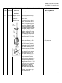
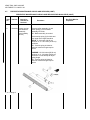
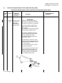
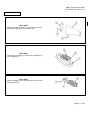
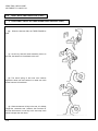
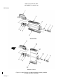
5
Quarterly Key and bolt
carrier assembly and bolt
assembly
(serviceability
check)
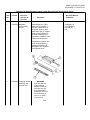
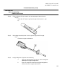
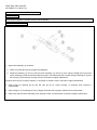
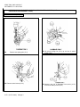
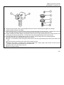
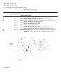
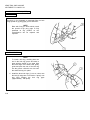
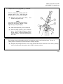
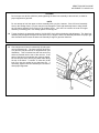
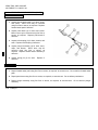
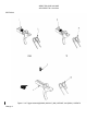
2-12 Change 5
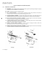
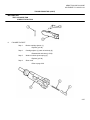
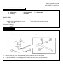
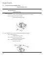
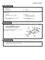
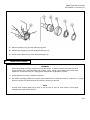
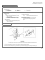
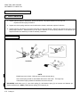
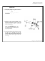
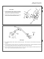
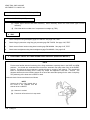
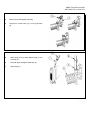
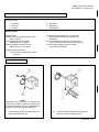
Remove and disassemble. Visually
inspect bolt assembly (1) for cracks,
especially in the area of the bolt cam pin
hole (2). Check for cracks on locking
lugs (3), for a cluster of pits or chipped
bolt face (4), and for an elongated firing
pin hole (5). If cracked or broken,
evacuate to support maintenance for
repair.
Defects are
found.
Check for worn or missing bolt rings (6)
Check for proper staggering of bolt rings
Insert the bolt assembly (1) into the key
and bolt carrier assembly (7). Turn key
and bolt carrier assembly (7) so the bolt
assembly (1) points down. The bolt assembly must not drop out. Remove bolt
assembly (p 2-35). Check for broken or
missing firing pin retaining pin (8) and
bolt cam pin (9); replace as necessary.
The bolt assembly drops out of
the key and bolt
carrier assembly
due to its own
weight. Missing or
broken firing pin
retaining pin or
bolt cam pin.
ARMY TM 9-1005-319-23&P
AIR FORCE TO 11W3 5-5-42
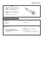
PREVENTIVE MAINTENANCE CHECKS AND SERVICES FOR M16A2 RIFLE (CONT)
Item
No.
Interval
Item to be
Checked or
Serviced
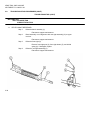
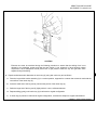
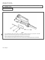
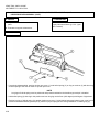
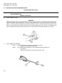
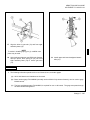
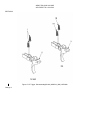
5
Quarterly Key and bolt
(cont)
carrier assembly
and bolt assembly (serviceability
check) (cont)
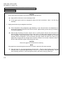
Procedure
Not Fully Mission
Capable if:
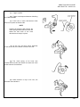
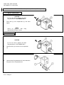
Check cartridge extractor (10),
extractor spring assembly (11),
cartridge ejector (12), and
ejector spring (13) for dirt and
serviceability. If dirty, clean,
lubricate and assemble. If
unserviceable, replace as
necessary.
Parts are missing
or unserviceable
Check key and bolt carrier
assembly (7) and carrier key
(14) for damage and looseness. If damaged or loose,
evacuate to support maintenance
Key and bolt
carrier assembly
or carrier key
is damaged, or
carrier key is
loose.
NOTE
If carrier key Is dented, evacuate to support maintenance.
Check firing pin 15) for
chips or breaks If damaged,
evacuate to support maintenance.
Firing pin is
damaged.
Pits or wear in area Illustrated (16) is permissable
2-13 Change 3
ARMY TM 9-1005-319-23&P
AIR FORCE TO 11W3-5-5-42
2-7.
PREVENTIVE MAINTENANCE CHECKS AND SERVICES (CONT).
PREVENTIVE MAINTENANCE CHECKS AND SERVICES FOR M16A2 RIFLE (CONT)
Item
No.
Interval
Item to be
Checked or
Serviced
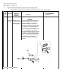
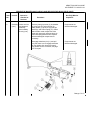
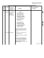
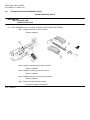
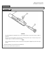
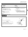
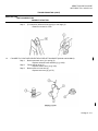
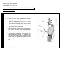
6
Quarterly Lower receiver
and buttstock
assembly
(serviceability
check)
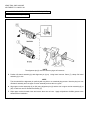
Procedure
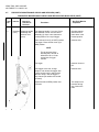
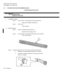
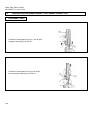
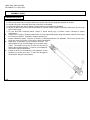
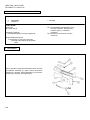
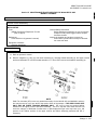
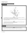
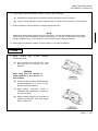
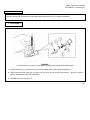
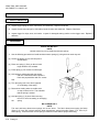
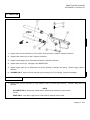
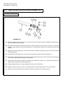
Remove buffer assembly (1) and
action spring (2) Check buffer
assembly for cracks
SH - Buffer assembly is cracked
Check action spring (2) for kinks and
free length Free length should be
RIFLE: 11 3/4 Inches (29 85 cm)
minimum to 13 1./2 inches (34 29 cm)
maximum
SH - If action spring is kinked or
does not meet free length requirements
CARBINE: 10 1/16 inches (25.56 cm)
minimum to 11 1/4 inches (28.58 cm)
maximum. Do not attempt to adjust
spring length
SH - If action spring is kinked or
does not meet free length requirements
2-14 Change 3
Not Fully Mission
Capable if:
ARMY TM 9-1005-319-23&P
AIR FORCE TO 11W3-5-5-42
PREVENTIVE MAINTENANCE CHECKS AND SERVICES FOR M16A2 RIFLE (CONT)
Item
No.
Interval
Item to be
Checked or
Serviced
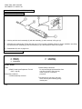
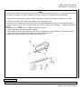
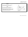
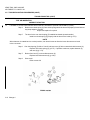
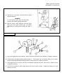
6
Quarterly Lower receiver
(cont)
and buttstock
assembly
(serviceability
check) (cont)
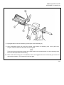
Procedure
Not Fully Mission
Capable if:
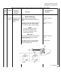
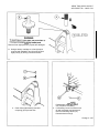
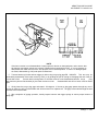
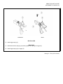
Remove pistol grip screw (3), lockwasher
(4), pistol grip (5), helical spring (6),
safety detent (7), pivot pin (8), pivot pin
detent (9), and helical spring (10). Clean
and lubricate metal components. Also
clean and generously lubricate pivot pin
holes and spring/detent holes. Replace
defective/damaged components as
necessary.
Components are
defective/damaged.
Disengage takedown pin (11) and pull
out, push back in to re-engage takedown
pin (an audible click should be heard).
If an audible click is not heard, see page
2-57 for repair.
Components are
defective/damaged.
Change 5 2-15
ARMY TM 9-1005-319-23&P
AIR FORCE TO 11W3-5-5-42
2-7.
PREVENTIVE MAINTENANCE CHECKS AND SERVICES (CONT).
PREVENTIVE MAINTENANCE CHECKS AND SERVICES FOR M16A2 RIFLE (CONT)
Item
No.
Interval
Item to be
Checked or
Serviced
6
Quarterly Lower receiver
(cont)
and buttstock
assembly
(serviceability
check) (cont)
Procedure
Not Fully Mission
Capable if:
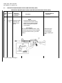
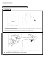
Lubricate helical compression spring and
takedown pin detent (11 ) by placing one
drop of lubricant on takedown pin detent
and lowering the buttstock assembly (12)
to vertical position. Allow the lubricant to
work Its way around the helical compression spring and takedown pin detent (11).
Check buttstock assembly(12) components for damage.
RIFLE ONLY
Under the following conditions, hairline
cracks (no chipped away material
allowed) originating from the buttplate
end of the buttstock are acceptable.
2-16 Change 5
Components are
damaged.
ARMY TM 9-1005-319-23&P
AIR FORCE TO 11W3-5-5-42
PREVENTIVE MAINTENANCE CHECKS AND SERVICES FOR M16A2 RIFLE (CONT)
Item
No.
Interval
Item to be
Checked or
Serviced
6
Quarterly Lower receiver
(cont)
and buttstock
assembly (serviceability check)
(cont)
Procedure
RIFLE ONLY
a. One hairline crack, not to exceed
1 in. (2.54 cm) in length, per side of
buttstock
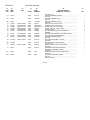
Not Fully Mission
Capable if:
The buttstock is
cracked in the
critical area or
does not meet the
crack criteria.
b. Two additional hairline cracks up
to 0.25 in. (0.64 cm) in length, per
side
of buttstock.
c. A total of three cracks per side
of the buttstock, originating from the
buttplate end, are allowable.
Cracks in the critical area at the front
end of the buttstock are not acceptable.
Check buttstock assembly (12) for
forward to rear movement and/or a
1/32 in. (0.079 cm) gap between the
buttstock assembly (12) and the
lower receiver (13). If forward to rear
movement and/or a 1/32 in. (0.079
cm) gap appears, tighten self-locking
screw. If still not tight, remove buttstock assembly and check for loose
lower receiver extension. If loose
evacuate to support maintenance.
If not loose, replace buttplate (14).
Lower receiver
extension cannot
be tightened.
Change 4 2-17
ARMY TM 9-1005-319-23&P
AIR FORCE TO 11W3-5-5-42
2-7.
PREVENTIVE MAINTENANCE CHECKS AND SERVICES (CONS).
PREVENTIVE MAINTENANCE CHECKS AND SERVICES FOR M16A2 RIFLE (CONT)
Item
No.
Interval
Item to be
Checked or
Serviced
6
Quarterly Lower receiver
(cont)
and buttstock
assembly
(serviceability
check) (cont)
Procedure
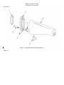
RIFLE ONLY
Small amounts of side-to-side, upand-down or rotational movement of
the buttstock assembly is acceptable.
(1) Cracks visible around the buttplate mounting holes while screws
are mounted
SH - Cracks are visible around mounting holes when installed on rifle.
(2) Cracks or separations around
the door assembly are visible when
the door assembly is closed
SH - Cracks are visible when door
assembly is closed.
(3) If buttplate is cracked in excess
of 0.25 in (O 64 cm) in length and extends through the buttplate (14). see
pg. 2-64 for repair
SH - If cracked in excess of 0 25 in.
extends thru buttplate
(4) The buttplate (14) should not be
removed other than for repair or replacement of parts at which time a
new self-locking screw, NSN 530501-147-8585, must be used.
2-18 Change 3
Not Fully Mission
Capable if:
ARMY TM 9-1005-319-23&P
AIR FORCE TO 11W3-5-5-42
PREVENTIVE MAINTENANCE CHECKS AND SERVICES FOR M16A2 RIFLE (CONT)
Item
No.
Interval
Item to be
Checked or
Serviced
6
Quarterly Lower receiver
(cont)
and buttstock
assembly
(serviceability
check) (cont)
Procedure
Not Fully Mission
Capable if:
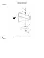
NOTE
If a weapons lower receiver is missing one
third or more of its exterior protective finish,
resulting in an unprotected/light reflecting surface,
it is candidate for overhaul. This missing finish
will be considered a
shortcoming.
This shortcoming requires action to obtain
a replacement weapon.
Once a replacement has
been received, evacuate
the original weapon to
depot for overhaul.
If scratched or worn shiny in spots,
repair in the same manner as outlined for upper receiver (see item 4
above).
7
Quarterly M16A2 Rifle
Assemble as in TM 9-1005-319-10
(operator’s manual).
Check sling for damage. If damaged,
replace.
Check for improperly assembled,
broken, missing, or damaged parts.
Check over all general appearance.
Replace parts as required and
authorize evacuation to support maintenance for repair.
Change 4 2-19
ARMY TM 9-1005-319-23&P
AIR FORCE TO 11W3-5-5-42
2-7.
PREVENTIVE MAINTENANCE CHECKS AND SERVICES (CONT).
PREVENTIVE MAINTENANCE CHECKS AND SERVICES FOR M16A2 RIFLE (CONT)
Item
No.
Interval
Item to be
Checked or
Serviced
8
Quarterly Annual DS safety
and serviceability
inspection and
gaging
Procedure
Check to ensure annual DS safety and
serviceability inspection and gaging has
been done and that the next gaging
and inspection is scheduled. If annual
gaging has not been performed within
the last year, notify support maintenance.
Not Fully Mission
Capable if:
Annual gaging
has not been
performed.
Section IV. TROUBLESHOOTING
2-8.
GENERAL.
a. This section contains unit level troubleshooting information for locating and correcting most of the operating troubles
which may develop in the M16A2 rifle, M4/M4A1 carbine. Each malfunction for the individual part or assembly is followed
by a list of tests or inspections which will help you to determine the corrective actions in the order listed.
b. This manual cannot list all malfunctions that may occur, nor all tests or inspections and corrective actions. If a
malfunction is not listed or is not corrected by listed corrective actions, see individual repair sections in the maintenance
procedures on each major assembly.
2-9.
TROUBLESHOOTING PROCEDURES. Refer to troubleshooting table for malfunctions, tests, and corrective
actions. The symptom index is provided for a quick reference of the malfunctions covered in the table.
2-20 Change 4
ARMY TM 9-1005 319-23&P
AIR FORCE TO 11W3 5-5-42
SYMPTOM INDEX
Troubleshooting
Procedures
Page
Failure of magazine to lock in rifle...................................................................................................................
Failure to feed..................................................................................................................................................
Failure to chamber ..........................................................................................................................................
Failure to lock ..................................................................................................................................................
Failure to fire....................................................................................................................................................
Failure to unlock ..............................................................................................................................................
Failure to extract..............................................................................................................................................
Failure to eject .................................................................................................................................................
Failure to cock .................................................................................................................................................
Short recoil ......................................................................................................................................................
Rifle cannot be zeroed.....................................................................................................................................
Failure to cycle with selector lever set on BURST...........................................................................................
Fires two rounds with one pull of trigger with selector lever set on SEMI
(double firing)...................................................................................................................................................
Fires with selector lever on SAFE or when trigger is released with selector
lever on SEMI ..................................................................................................................................................
Bolt assembly falls to lock to rear after firing last round ..................................................................................
2-21
2-22
2-22
2-23
2-24
2-26
2-26
2-27
2-28
2-28
2-30
2-31
2-31
2-31
2-32
TROUBLESHOOTING
MALFUNCTION
TEST OR INSPECTION
CORRECTIVE ACTION
1.
FAILURE OF MAGAZINE TO LOCK IN RIFLE.
Step 1.
Dirty or corroded magazine catch (1).
Disassemble and clean.
Step 2
Defective magazine catch spring (2)
Evacuate to support maintenance.
Step 3
Worn or broken magazine catch (1).
Evacuate to support maintenance
2-21
ARMY TM 9-1005-319-23&P
AIR FORCE TO 11W3-5-5-42
2-9.
TROUBLESHOOTING PROCEDURES (CONT).
TROUBLESHOOTING (CONT)
MALFUNCTION
TEST OR INSPECTION
CORRECTIVE ACTION
2.
FAILURE TO FEED
Step 1.
Magazine catch spring weak or broken
Evacuate to support maintenance
Step 2.
Magazine catch (1) defective.
Evacuate to support maintenance
Step 3.
Magazine catch (1) out of adjustment (will not retain magazine)
Refer to operator’s manual.
Step 4.
Short recoil.
Refer to page 2-28
3.
FAILURE TO CHAMBER.
Step 1.
Weak or broken action spring (1), RIFLE ONLY (free length 11 3/4 inches (29.85
cm) minimum to 13 1.’2 Inches (34 29 cm) maximum) CARBINE ONLY
(10 1 16 inches (2S 56 cm) minimum to 11 1,4 inches (28 58 cm) maximum)
Replace action spring (p 2-57)
2-22 Change 3
ARMY TM 9-1005-319-23&P
AIR FORCE TO 11W3-5-5-42
TROUBLESHOOTING (CONT)
MALFUNCTION
TEST OR INSPECTION
CORRECTIVE ACTION
Step 2.
Short recoil
Refer to page 2-28
4.
FAILURE TO LOCK
Step 1.
Bolt cam pin (1) missing
Replace (p 2-35)
Step 2.
Step 3.
Loose or damaged bolt carrier key (2).
a.
Evacuate to support maintenance.
b.
Dented bolt carrier key may be repaired (p 2 35).
Improperly assembled extractor spring assembly (3)
Assemble correctly (p 2-38).
2-23
ARMY TM 9-1005-319-23&P
AIR FORCE TO 11W3-5-5-42
2-9.
TROUBLESHOOTING PROCEDURES (CONT).
TROUBLESHOOTING (CONT)
MALFUNCTION
TEST OR INSPECTION
CORRECTIVE ACTION
4.
FAILURE TO LOCK (CONT)
Step 4.
Bent gas tube 14J
a
Adjust to Its original configuration by bending in area of handguard assembly.
b
If the gas tube cannot be returned to Its original configuration,
evacuate the rifle to support maintenance
Step 5
Weak or broken action spring (5); RIFLE ONLY: (free length 11 3/4 inches (29,85
cm) minimum to 13 1,/2 Inches (34 29 cm) maximum). CARBINE ONLY
(10 1/16 Inches (25 56 cm) minimum to 11 1,4 inches (28 58 cm) maximum
Replace action spring (p 2-571
5.
FAILURE TO FIRE.
Step 1
Broken or chipped firing pin (1).
Evacuate to support maintenance.
2-24 Change 3
ARMY TM 9-1005-319-23&P
AIR FORCE TO 11W3-5-5-42
TROUBLESHOOTING (CONT)
MALFUNCTION
TEST OR INSPECTION
CORRECTIVE ACTION
Step 2
Carbon buildup in firing pin recess inside bolt assembly
Remove cartridge extractor and clean recess with pipe cleaner
(Item 11, app D), refer to operator’s manual.
Step 3.
Firing mechanism (2) and or lower receiver assembly (31 improperly
assembled or has worn, broken, or missing parts.
Evacuate to support maintenance
Step 4.
Broken, defective, or missing firing pin retaining pin (4).
Replace (p 2-35)
Step 5.
Selector lever (5) frozen on SAFE position.
Evacuate to support maintenance
2-25
ARMY TM 9-1005-319-23&P
AIR FORCE TO 11W3-5-5-42
2-9.
TROUBLESHOOTING PROCEDURES (CONT).
TROUBLESHOOTING (CONT)
MALFUNCTION
TEST OR INSPECTION
CORRECTIVE ACTION
6.
FAILURE TO UNLOCK.
Step 1.
Burred locking lugs (1) on bolt assembly.
Remove burrs.
Step 2.
Burred lugs (2) on barrel extension
Remove burrs.
Step 3
Short recoil.
Refer to page 2-28.
7.
FAILURE TO EXTRACT.
Step 1.
Defective extractor pin (1), cartridge extractor (2), and or extractor spring
assembly (3).
Replace extractor pin (1), cartridge extractor (2), and or extra(:tor
spring assembly (3) (p 2-381
Step 2.
Short recoil
Refer to page 2-28
NOTE
Rubber insert and spring are an assembly Illustration shows Insert out of assembly for clarification only
Do not remove the rubber Insert from the extractor spring assembly.
2-26
ARMY TM 9-1005-319-23&P
AIR FORCE TO 11W3-5-5-42
TROUBLESHOOTING (CONT)
MALFUNCTION
TEST OR INSPECTION
CORRECTIVE ACTION
8.
FAILURE TO EJECT.
Step 1.
Broken cartridge ejector (1).
Replace (p 2-38).
Step 2.
Cartridge ejector (1) stuck in bolt body (2).
Disassemble and clean (p 2-38).
Step 3.
Weak or broken ejector spring (3).
Replace (p 2-38)
Step 4.
Short recoil
Refer to page 2-28.
2-27
ARMY TM 9-1005-319-23&P
AIR FORCE TO 11W3-5-5-42
2-9.
TROUBLESHOOTING PROCEDURES (CONT).
TROUBLESHOOTING (CONT)
MALFUNCTION
TEST OR INSPECTION
CORRECTIVE ACTION
9.
FAILURE TO COCK
Step 1
Worn, broken, or missing parts of firing mechanism
Evacuate to support maintenance.
Step 2
Short recoil
Refer to below
10
SHORT RECOIL
Step 1
Broken or damaged action spring (1).
Replace action spring (p 2-57).
Step 2
Unlubricated or dirty action spring and receiver extension
Clean and lubricate
Step 3
2-28 Change 3
Improper gap space or worn, missing, or broken bolt rings (2)
a.
Stagger bolt ring gaps (approximately 13 turn apart}
b.
Evacuate to support maintenance if bolt rings are worn,
broken, or missing.
ARMY TM 9-1005-319-23&P
AIR FORCE TO 11W3-5-5-42
TROUBLESHOOTING (CONT)
MALFUNCTION
TEST OR INSPECTION
CORRECTIVE ACTION
Step 4.
Carbon build-up or foreign matter In the narrow passage of the bolt carrier
key (3).
Clean with CLP (Item 9, app D) and a pipe cleaner (Item 11, app
D).
Step 5.
Gas leakage caused by broken or loose gas tube (4) around front sight
base.
Evacuate to support maintenance.
Step 6.
Improper alignment of gas tube and carrier key.
a.
Adjust gas tube alignment by bending in area of handguard
assembly to Its original configuration
b.
If gas tube cannot be returned to Its original configuration,
evacuate the rifle to support maintenance.
2-29
ARMY TM 9-1005-319-23&P
AIR FORCE TO 11W3-5-5-42
2-9.
TROUBLESHOOTING PROCEDURES (CONT).
TROUBLESHOOTING (CONT)
MALFUNCTION
TEST OR INSPECTION
CORRECTIVE ACTION
11.
RIFLE CANNOT BE ZEROED.
Step 1.
Defective barrel assembly (1).
Evacuate to support maintenance
Step 2.
Barrel assembly out of alignment with rear sight assembly (2) on upper
receiver.
Evacuate to support maintenance
Step 3.
Defective front sight (3).
Remove front sight post (4), front sight detent (5), and helical
spring (6). If damaged, replace.
Step 4.
2-30
Defective -ear sight assembly (2).
Evacuate to support maintenance.
ARMY TM 9-1005-319-23&P
AIR FORCE TO 11W3-5-5-42
TROUBLESHOOTING (CONT)
MALFUNCTION
TEST OR INSPECTION
CORRECTIVE ACTION
12.
FAILURE TO CYCLE WITH SELECTOR LEVER SET ON BURST (M16A2 AND M4).
Faulty selector lever or broken cam, cam clutch spring, or burst disconnector.
Evacuate to support maintenance.
12.1. FAILURE TO CYCLE WITH SELECTOR LEVER SET ON AUTO (M4A1).
Faulty selector lever.
Evacuate to support maintenance.
13.
FIRES TWO ROUNDS WITH ONE PULL OF TRIGGER WITH SELECTOR LEVER SET ON
SEMI (DOUBLE FIRING).
Perform function test.
If any part of function test (p 2-68) fails, evacuate to support maintenance.
14.
FIRES WITH SELECTOR LEVER ON SAFE OR WHEN TRIGGER IS RELEASED WITH
SELECTOR LEVER ON SEMI.
Worn, broken, or missing parts of firing mechanism.
Evacuate to support maintenance.
Change 4 2-31
ARMY TM 9-1005-319-23&P
AIR FORCE TO 11W3-5-5-42
2-9.
TROUBLESHOOTING PROCEDURES (CONT).
TROUBLESHOOTING (CONT)
MALFUNCTION
TEST OR INSPECTION
CORRECTIVE ACTION
15
BOLT ASSEMBLY FAILS TO LOCK TO REAR AFTER FIRING LAST ROUND.
Step 1. Magazine follower (1) worn or broken.
Replace magazine.
Step 2. Magazine catch spring (2) weak or broken.
Replace magazine.
Step 3. Magazine feeder lips (3) bent or broken.
Replace magazine.
Step 4. Magazine follower (1) binds during operation.
Replace magazine.
Step 5. Broken bolt catch (4) and/or spring.
Evacuate to support maintenance.
2-32 Change 5
ARMY TM 9-1005-319-23&P
AIR FORCE TO 11W3-5-5-42
Section V. MAINTENANCE PROCEDURES
2-10. INITIAL SETUP. The following information will reduce the space required for the initial setup portion of the
maintenance procedures.
a. Materials/Parts required are not listed unless they apply to the procedure
b. Personnel Required is listed only if the task requires more than one person If Personnel Required Is not listed, It
means one person can do the job.
c. The normal standard equipment condition Is that the item is removed from the en(1 Item or next higher assembly
and is in the assembled condition. Equipment Condition is not listed unless some other condition is required.
d. The approximate time required Is listed on the applicable Maintenance Allocation Chart (MAC).
e. When the term evacuate to support maintenance is used, the entire rifle must be evacuated.
2-11.
LUBRICATION GENERAL.
a. Whenever the term "cleaner, lubricant, and preservative (CLP)" or the words "lubricant", "lube", "LSA", or "LAW" are
cited In this TM, they are to be interpreted to mean CLP (Item 9, app D), weapons lubricating oil (LSA) (Item 23, app D), or
weapons lubricating oil (LAW) (Item 22, app D) can be utilized as applicable The following constraints must be adhered to:
b. Under all but the coldest arctic conditions, LSA or CLP are the lubricants to use on the rifle. Either may be used at
100F (230C) and above. However, do not use both on the same rifle at the same time.
c. LAW is the lubricant to use during cold arctic conditions, + 100F (12C) and below
d. Any of the lubricants may be used from 10°F to + 100F (230C to 12°C)
e. ARMY ONLY: Do not mix lubricants on the same rifle The rifle must be thoroughly cleaned during change from one
lubricant to another Dry Cleaning Solvent (SD) (Item 16, app D) is recommended for cleaning during change from one
lubricant to another.
f. Rifle Bore Cleaner (RBC) (item 12, app D) may be used to remove carbon buildup In the bore and other portions of
the rifle.
2-33
ARMY TM 9-1005-319-23&P
AIR FORCE TO 11W3-5-5-42
2-12.
MAJOR COMPONENTS OF M16A2 RIFLE AND CARBINES.
This task covers disassembly
INITIAL SETUP:
References
TM 9-1005-319-10 (operator’s manual)
Equipment Conditions
Rifle and Carbines assembled
General Safety Instructions
Before starting an inspection, be sure to
clear the weapon. Do not keep live
ammunition near the work area.
To avoid injury to your eyes, use care when
removing and installing spring-loaded
parts.
Below direct support maintenance, do not interchange bolt assemblies from one weapon
to another. Doing so may result in injury to,
or death of, personnel.
DISASSEMBLY
a. Refer to operator’s manual.
b. Remove magazine (1), sling (2), bolt carrier assembly (3), charging handle assembly (4), and upper receiver and
barrel assembly (5), carrying handle assembly (5.1), from lower receiver and buttstock assembly (6).
NOTE
Solid Film Lubricant (SFL) is the only authorized touchup for the Ml 16A2 rifle and M4/M4A1 carbines and
may be used on up to one third of the exterior finish of the weapon. FOR ARMY CONUS USE ONLY AND
AIR FORCE TRAINING WEAPONS ONLY: SFL may be used as touchup without limitation on the upper
receiver and barrel assembly. This is to say that units which DO NOT fall under the category of Divisional
Combat Units or rapid deployment type units may have up to 100 percent of the exterior surface of the
upper receiver and barrel assembly protected with SFL if necessary.
2-34 Change 4
ARMY TM 9-1005-319-23&P
AIR FORCE TO 11W3-5-5-42
12-13. BOLT CARRIER ASSEMBLY.
This task covers:
a. Disassembly
b. Cleaning
c. Inspection/Repair
d.
e.
Lubrication
Reassembly
INITIAL SETUP:
Tools
(ARMY) Small Arms Repairman Tool Kit
(item 3, app B)
Bolt Carrier Key Tool (item 11, figure C-17)
General Safety Instructions
Bolt cam pin must be installed or rifle will
blow up while firing the first round. If the
bolt cam pin is not installed, injury to, or
death of, personnel may result.
References
TM 9-1005-319-10 (operator’s manual)
Equipment Conditions
2-34 Bolt carrier assembly removed
Do not interchange bolt assemblies from one
rifle to another. Doing so may result in injury
to, or death of, personnel.
a. DISASSEMBLY
CAUTION
Do not spread or close legs of firing
pin retaining pin (1).
1. Remove firing pin retaining pin (1). Tilt key and
bolt carrier assembly (2) and catch firing pin
(3) as it drops out.
2. Rotate bolt cam pin (4) one quarter turn and lift
straight up to remove.
3. Remove bolt assembly (5) from key and bolt
carrier assembly (2).
NOTE
For disassembly of bolt assembly
(5), see page 2-38.
Change 5 2-35
ARMY TM 9-1005-319-23&P
AIR FORCE TO 11W3-5-5-42
12-13. BOLT CARRIER ASSEMBLY (CONT).
b. CLEANING
Clean all items (operator’s manual). Remove carbon deposits.
c. INSPECTION/REPAIR
1. Inspect bolt assembly (1) as follows:
a. Check to see that the bolt ring (2) gaps are staggered.
b. Install bolt assembly (1) into key and bolt carrier assembly (3). Check for worn rings by holding the key and bolt
carrier assembly (3) with the bolt assembly facing down. If bolt assembly falls out after firing pin retaining pin (4) and
bolt cam pin (5) are removed, the rings are worn. Evacuate to support maintenance.
2.Inspect carrier key (6) for dents, distortion, or looseness. If dented or loose, evacuate to support maintenance.
3. Inspect firing pin retaining pin (4) and bolt cam pin (5) for cracks, damage, or excessive wear. Replace if
unserviceable.
4. Inspect firing pin (7) for damage or If tip is chipped. Evacuate rifle to support maintenance if unserviceable
5. Inspect key and bolt carrier assembly (3) for damage or wear. If unserviceable, evacuate to support maintenance.
2-36
ARMY TM 9-1005-319-23&P
AIR FORCE TO 11W3-5-5-42
CAUTION
Extreme care must be exercised during the following procedure to assure that the striking force is not
directed to the attaching screws and that the tube portion is not enlarged or flared beyond original
requirement. Such enlargement would permit loss of gas pressure when the key and gas tube come
together during functioning.
6. Repair small dents and/or distortions in carrier key (6) using bolt carrier key tool as follows:
a. Place the key and bolt carrier assembly (3) in a vertical position, supported In a manner that contact is made with the
rear surface of the carrier key (6).
b. Insert the small end of the key tool (8) into the tube portion of the carrier key (6).
c. Strike the large end of the key tool (8) lightly with a 3 ounce, soft-brass hammer.
d. Repeat striking (gently) until carrier key (6) is reformed to original configuration.
e. If carrier key (6) cannot be reformed to original configuration, evacuate the weapon to support maintenance.
Change 5 2-36.1/(2-36.2 blank)
ARMY TM 9-1005-319-23&P
AIR FORCE TO 11W3-5-5-42
d. LUBRICATION
Lubricate all Items (p 2 33) (operator’s manual)
e. REASSEMBLY
WARNING
Do not Interchange bolt assemblies from one rifle to another Doing so may result In Injury, or death of,
personnel.
Bolt cam pin must be Installed or rifle will blow up while firing the first round. If the bolt cam pin is not
Installed, Injury to, or death of, personnel may result
NOTE
Before installing bolt assembly, check to see that the bolt ring gaps are staggered to prevent loss of gas
pressure
1. Install bolt assembly (1) In key and bolt carrier assembly (2)
2.Install bolt cam pin (3) and rotate one quarter turn
2-37
ARMY TM 9-1005-319-23&P
AIR FORCE TO 11W3-5-5-42
2-13.
BOLT CARRIER ASSEMBLY (CONT).
e. REASSEMBLY (CONT)
3. Hold key and bolt carrier assembly (2) with bolt assembly (1) down and drop in firing pin (4).
4. Install firing pin retaining pin (5) from left side only to ensure proper installation Check for proper installation by holding
key and bolt carrier assembly (2) with bolt assembly (1) up, then attempt to shake out firing pin.
5. Reassemble rifle, refer to page 2-68.
2-14.
BOLT ASSEMBLY.
This task covers:
a. Removal
b. Cleaning
c. Inspection
d.
e.
Lubrication
Reassembly
INITIAL SETUP:
Tools
(ARMY) Small Arms Repairman Tool Kit
(item 3, app B)
Equipment Conditions
2-35 Bolt assembly removed
General Safety Instructions
Do not Interchange bolt assemblies from
one rifle to another. Doing so may
result in injury to, or death of,
personnel.
To avoid injury to your eyes, use care
when removing and installing springloaded parts.
2-38
ARMY TM 9-1005-319-23&P
AIR FORCE TO 11W3-5-5-42
a.
DISASSEMBLY
NOTE
Do not separate cartridge extractor
and extractor spring assembly
unless replacement of either or both
is required
Do not remove the rubber Insert
from the extractor spring assembly
1. Push out extractor pin (1) and remove cartridge extractor (2) and extractor spring assembly (3) as a unit
2. If required, twist extractor spring assembly (3) counterclockwise to remove from cartridge extractor (2).
CAUTION
Be sure to use vise law protective
caps
3. Hold bolt body In vise and remove spring pin
(4) using 1 16 Inch punch and hammer
2-39
ARMY TM 9-1005-319-23&P
AIR FORCE TO 11W3-5-5-42
2-14.
a.
BOLT ASSEMBLY (CONT).
DISASSEMBLY (CONT)
WARNING
To avoid injury to your eyes, use care
when removing and installing springloaded parts.
4.
b.
Remove punch, be sure to catch cartridge
elector (5) and ejector spring (6) to prevent loss
CLEANING
CAUTION
Do not distort extractor spring assembly during cleaning.
Clean all Items (operator’s manual). Remove carbon deposits.
c.
INSPECTION/REPAIR
1. Check bolt rings (1) for damage and proper stagger
(gaps approximately 3 turn apart).
2. Inspect for cracks or damage, especially around bolt
cam pin hole (2) and locking lugs (3). If cracked or
damaged evacuate to support maintenance.
3. Inspect cartridge extractor (4), extractor spring
assembly (5), and extractor pin (6) for cracks,
breaks, chips, and other damage. Pay close
attention to cartridge extractor lip (7). If damaged,
replace.
4. Inspect cartridge ejector (8) and ejector spring (9) for
cracks, breaks, and chips If damaged, replace.
2-40
ARMY TM 9-1005-319-23&P
AIR FORCE TO 11W3-5-5-42
d.
LUBRICATION
Lightly lubricate all items (p 2 33) (operator’s manual)
e.
REASSEMBLY
WARNING
To avoid Injury to your eyes, use care
when removing and Installing spring
loaded parts.
Do not Interchange bolt assemblies
from one rifle to another Doing so
may result In injury to, or death of,
personnel.
CAUTION
Be sure to use vise jaw protective caps
1. Place bolt body (1) in a vise and start spring pin (2) In hole.
2. Install ejector spring (3) and cartridge ejector (4). Align groove on cartridge ejector (4) so that spring pin 12) can be
Installed
3. Compress and hold ejector spring and cartridge
ejector In place with a 3 8 inch punch.
4. Using hammer and 1 16 Inch punch, complete
Installation of spring pin (2) so that the ends are
flush with the out side of bolt body (1).
2-41
ARMY TM 9-1005-319-23&P
AIR FORCE TO 11W3-5-5-42
2-14.
e.
BOLT ASSEMBLY (CONT).
REASSEMBLY (CONT)
NOTE
Do not disassemble rubber Insert from
extractor spring assembly.
5. If removed, Insert large end of extractor spring
assembly (5) into cartridge extractor (6) and seat
by pushing and turning clockwise.
6 Position cartridge extractor (6) and ex tractor
spring assembly (5) on bolt body (1).
7 Compress extractor spring assembly (5) and
cartridge extractor (6) to align holes.
8. Install extractor pin (7) by hand.
9. Reassemble rifle, refer to page 2-68.
2-42
ARMY TM 9-1005-319-23&P
AIR FORCE TO 11W3-5-5-42
2-15.
CHARGING HANDLE ASSEMBLY.
This task covers:
a. Disassembly
b. Cleaning
c. Inspection/Repair
d. Lubrication
e.
Reassembly
INITIAL SETUP:
Tools
(ARMY) Small Arms Repairman Tool Kit
(item 3, app B)
Equipment Conditions
2-34 Charging handle assembly removed
a.
References
TM 9-1005-319-10 (operator’s manual)
DISASSEMBLY
WARNING
To avoid injury to eyes, use care when removing and installing spring-loaded parts.
1. Remove spring pin (1) from charging handle (2) using a hammer and 1/16 inch punch.
2. As punch is withdrawn, catch charging handle latch (3) and helical spring (4) to prevent loss.
2-43
ARMY TM 9-1005-319-23&P
AIR FORCE TO 11W3-5-5-42
2-15.
b.
CHARGING HANDLE ASSEMBLY (CONT).
CLEANING
Clean all Items (operator’s manual) Remove carbon deposits.
c.
INSPECTION/REPAIR
Inspect all Items for breaks, cracks, or damage Replace all unserviceable Items
d.
LUBRICATION
Lightly lubricate all Items (p 2-33) (operator’s manual)
e.
REASSEMBLY
1. Position helical spring I1) and charging handle latch (2) in chdrgiin(J handle 13) Align holes and hold In position
2. Install spring pin (4) using a hammer Make sure spring pin is flush
3. Reassemble rifle, refer to page 2 68
2-44
ARMY TM 9-1005-319-23 & P
AIR FORCE TO 11W3-5-5-42
2-16.
UPPER RECEIVER AND BARREL ASSEMBLY, RIFLE BARREL ASSEMBLY, AND
UPPER RECEIVER ASSEMBLY.
This task covers:
a. Disassembly
b. Cleaning
c. Inspection
d. Repair
INITIAL SETUP
Tools
(ARMY) Small Arms Repairman Tool Kit
(item 3, app B)
Front sight post removal and installation
tool (fig. E-2, app E)
Front sight detent depressor (fig. E-1,
app E)
Materials/Parts
Lubricants (app D)
loaded parts.
a.
e. Lubrication
f. Reassembly
References
TM 9-1005-319-10 (operator’s manual)
Equipment Conditions
2-34
Upper receiver and barrel assembly
removed from lower receiver
General Safety Instructions
To avoid injury to your eyes, use care
when removing and installing spring-
DISASSEMBLY
CAUTION
Do not use a screwdriver or any other tool when removing the handguard assemblies. Doing so may
damage the handguard assemblies and/or slip ring. Do not remove heat shield for any reason. Doing
so will damage the heat shield and the handguard assemblies will have to be replaced.
NOTE
Refer to operator’s manual for "buddy system" procedure on removing handguard assemblies.
2-45
ARMY TM 9-1005 319 23&P
AIR FORCE TO 1 1W3 5-5 42
2-16.
UPPER RECEIVER AND BARREL ASSEMBLY, RIFLE BARREL ASSEMBLY, AND
UPPER RECEIVER ASSEMBLY (CONT).
a.
DISASSEMBLY (CONT)
1.
Push down on handguard slip ring (1) and lift upper
handguard assembly (2) up and out.
2.
Push down on handguard slip ring (1) and lift the
lower handguard assembly (3) up and out.
2-46
ARMY TM 9-1005-319-23 & P
AIR FORCE TO 1 1W3-5-5 42
NOTE
Remove front sight posts only if parts are damaged.
3. Using a dummy cartridge or a font sight post
removal and installation tool (4).removed front
sight post (6) by turning counter clockwise.
4. Catch front sight detent(7) and helical spring (8) to prevent loss.
NOTE
Disassemble small sling swivel
only if repair is necessary.
5. If necessary, knock out tubular rivet
(9) with a hammer and punch and
remove small sling swivel (10).
Discard tubular rivet (9).
Change 3 2-47
ARMY TM 9-1005-319-23 & P
AIR FORCE TO 1 1W3-5-5-42
2-16. UPPER RECEIVE AND BARREL ASSEMBLY, RIFLE BARREL ASSEMBLY, AND
UPPER RECEIVER ASSEMBLY (CONT).
a. DISASSEMBLY (CONT)
5A.
Remove two spring pins (10 1)
5C. Remove swivel mount (10.3).
2-47.1 (2-47.2 blank) Change 3
5B. Lift swivel locking bar (10 2) up and out of swivel
mount (10 3)
5D. Remove rivet (10 4) Separate front swivel (10 5)
from swivel blank) mount (10 3)
ARMY TM 9-1005-319-23&P
AIR FORCE TO 1 1W3-5-5-42
2-16. UPPER RECEIVER AND BARREL ASSEMBLY, RIFLE BARREL ASSEMBLY, AND UPPER RECEIVER
ASSEMBLY (CONT).
a. DISASSEMBLY (CONT)
NOTE
Do not disassemble further unless repair is necessary. Headless grooved pin (11) may bind may bind
against the forward assist housing and require some additional force to remove.
6.
7.
Remove retaining ring (12) and slide headles grooved pin (11) out to the rear.
Catch cover spring (13) and ejection port cover (14) to prevent loss as headless grooved pin is with-drawn.
2-48 Change 4
ARMY TM 9-1005-319-23&P
AIR FORCE TO 11W3-5-5-42
M4/M4A1 ONLY
NOTE
Do not remove the carrying handle assembly nut (2 each) or clamp for normal maintenance. If carrying handle assembly
nut or clamp are missing or the clamp is damaged to the point of being non-functional they may be replaced.
7.1. Disassemble as follows only if required to replace damaged or missing carrying handle assembly nut or clamp.
a. Observe the position of the clamp (15) in relation to the carrying handle (16).
b. Using care not to damage the surface finish, remove carrying handle assembly nut(s) (17) and clamp as required.
c. Inspect mating surfaces of the carrying handle (16) and the clamp (15) for damage. If damaged replace the
damaged
part.
d. Inspect for other damage, rust, etc. Repair or replace as required.
e. Apply a light coat of lubricant to all mating surfaces.
f. Install clamp (15) paying close attention to ensure that it is installed in its original position. The forward end of the
clamp (15) must not extend past the forward end of the carrying handle (16).
g. Taking care not to cross thread, install handle assembly nut (17).
b.
CLEANING
Clean all items (operator’s manual).
Change 4 2-48.1/(2-48.2 blank)
ARMY TM 9-1005-319-23&P
AIR FORCE TO 11W3-5-5-42
c.
INSPECTION
1. Inspect handguard assemblies for breaks separation, and cracks using the following guidelines:
a. Breaks and separations of material which prevent proper retention or interfere with functioning of the rifle will be
cause for handguard assembly rejection and replacement.
b. M16A2 handguard assemblies may have up to two of the three front retaining tabs missing (1). M4/M4A1 may not
have any front retaining tabs (1) missing. If all front retaining tabs for the M1 6A2 are missing, or any of the tabs for
the M4/M4A1 are missing, handguard assemblies must be replaced.
c. Cracks up to one inch in length are acceptable provided they do not extend into the retaining flange (CRITICAL
AREA) (2).
d. Replace severely cracked or damaged handguard assemblies. Handguard assemblies which have a heat shield
which is loose enough to rattle when installed on the rifle must be replaced.
2. Inspect front sight assembly for chips, breaks, and cracks. Evacuate to support maintenance if broken, cracked, or
bent.
3. Inspect front sight area for evidence of gas leakage around gas tube. Evacuate to support maintenance if short recoil
results from gas leakage.
4. Inspect front sight post, front sight detent, and helical spring for damage. If damaged, replace.
Change 5 2-49
ARMY TM 9-1005-319-23&P
AIR FORCE TO 11 W3-5-5-42
2-16.
UPPER RECEIVER AND BARREL ASSEMBLY, RIFLE BARREL ASSEMBLY, AND UPPER RECEIVER
ASSEMBLY (CONT).
c. INSPECTION (CONT)
5.
Inspect barrel for pits in bore, burrs, broken or worn locking lugs, and surface cracks and defects.
Pits no wider than a land or groove and 3/8 inch (0.953 cm) or less in length are allowable in the bore.
Uniformly fine pits in a densely pitted area of the bore are allowable.
Lands that appear dark due to coating of gliding metal from projectiles are allowable.
Striping of lands and grooves shall not be cause for rejection unless support maintenance determines by use of the
barrel erosion gage.
e. For pits other than mentioned above, broken or burred locking lugs, or surface cracks, evacuate to support
maintenance.
6. Inspect bore for ringing. Definitely ringed bores or bores ringed sufficiently to bulge the outside surfaces of the barrel
are causes for rejection. Evacuate to support maintenance.
7. Inspect chamber for pitting. Fine pits, or fine pits in a densely pitted area, are allowable. Pits 1/8 inch (0.318 cm) in
length are cause for rejection. Evacuate to support maintenance.
8. Hand check compensator (3) for looseness on barrel. The
third (middle) slot (4) must be straight up at top dead center
(TDC). The alignment may vary as much as one half the
width of the slot either direction. If loose or out of alignment,
evacuate to support maintenance.
9. Inspect all items for serviceability in and tightness of latch
assembly on ejection port cover. If items are damaged or
nonfunctional, they are unserviceable.
a.
b.
c.
d.
2-50
ARMY TM 9-1005-319-23&P
AIR FORCE TO 11W3-5-5-42
10. Rotate and test elevation index (5) and windage knob (6) for ease of functioning and legibility of markings.
11. Inspect elevation knob zero as follows:
a. Rotate elevation knob (7) counterclockwise until the rear sight assembly is all the way down. If a whole click is not felt
as the rear sight assembly stops, the rear sight assembly has bottomed out and will not pivot freely.
b. Position elevation knob back slightly to Its last whole click so the rear sight assembly base (8) is under tension of the
ball bearing (9) and helical spring (10). The 300 meter mark should align with the mark on the receiver.
c. If the 300 meter mark is not aligned with the mark on receiver, slip the range scale in the following manner:
(1) Position the 300 meter mark with the mark on the receiver.
(2) Insert a 1/16 inch allen wrench through the access hole of the rear sight assembly base and into the Index screw
(11).
(3) Loosen the index screw three turns and leave the wrench in place.
(4) Rotate lower portion of elevation knob counterclockwise until it stops (range scale should not have moved).
Elevation knob should be positioned on its last whole click.
(5) Tighten index screw and remove wrench.
(6) Check for proper setting.
2-51
ARMY TM 9-1005 319 23&P
AIR FORCE TO 1 1W3-5-5 42
2-16. UPPER RECEIVER AND BARREL ASSEMBLY, RIFLE BARREL ASSEMBLY, AND
UPPER RECEIVER ASSEMBLY (CONT).
d. REPAIR
1. Replace all authorized unserviceable
parts
e. LUBRICATION
Lightly lubricate all Items (p 2 311 (oper
ator’s manual)
2. Evacuate to support maintenance.
f. REASSEMBLY
1. If previously disassembled, position election port cover 11) and helical spring (2) on Lip per receiver (3) with short leg
of helical spring to the rear on Inside of ejection port cover
NOTE
Long legs of helical spring must be positioned and pretensioned before the headless grooved pin is installed
2. Hold helical spring (2) short leg In this position and turn long leg one half turn (180 degrees) with fingers of right hand
3. Position long leg of helical spring (21 against election port cover (1) Hold helical spring and election port cover in this
position and Install headless grooved pin (4) Check for proper spring tension during installation of retaining ring (5)
2-52
ARMY TM 9-1005-319-23 & P
AIR FORCE TO 1 1W3-5-5-42
RIFLE ONLY
4. If previously disassembled, position small sling swivel
(6) and install new tubular rivet (7) using center punch
and hammer to spread and flare the hollow head of
the tubular rivet.
4B.
CARBINE ONLY
NOTE
It is recommended that the swivel mount be
placed on the left side of the carbine for right
handed operators and on the right side for left
handed operators. This will keep the sling out of
the way when the carbine is used.
Install swivel mount (7.2).
4A.
CARBINE ONLY
Install front swivel (7.1) to swivel mount (7.2) with
new rivet (7.3) using center punch and hammer to
spread and flare the hollow head of the tubular
rivet.
CARBINE ONLY
4C.
Place swivel locking bar (7.4) in swivel mount
(7.2).
Change 4 2-53
ARMY TM 9-1005-319-23&P
AIR FORCE TO 11 W3-5-5-42
2-16. UPPER RECEIVER AND BARREL ASSEMBLY, RIFLE BARREL ASSEMBLY, AND UPPER RECEIVER
ASSEMBLY (CONT).
f.
REASSEMBLY (CONT)
CARBINE ONLY
4D. Install two spring pins (7 5)
2-53.1/(2-53.2 blank) Change 3
5. Position helical spring (8) and front sight detent (9).
ARMY TM 9-1005-319-23&P
AIR FORCE TO 11 W3-5-5-42
2-16. UPPER RECEIVER AND BARREL ASSEMBLY, RIFLE BARREL ASSEMBLY, AND UPPER RECEIVER
ASSEMBLY (CONT).
t.
REASSEMBLY (CONT)
7. Mechanical Zero Procedures (A.F. Only).
a. Mark a piece of plastic card stock or rigid paper
with lines from 1 to 5mm in 1 mm increments Set
the card on the front sight frame and check the
height of the top of the front sight post.
b. Using a dummy round or front sight post tool
adjust the front sight so the top of the front sight
post is 5mm above the machined surfaces of the
front sight frame.
2-54 Change 4
ARMY TM 9-1005-319-23 & P
AIR FORCE TO 1 1W3-5-5-42
c. Visually check the front sight post top height by using the marked plastic or paper card. Card must set level on the
machined surfaces of the front sight frame to obtain an accurate reading
NOTE
This procedure, when used In conjunction with rear sight mechanical zero adjustment. will give an
approximate battle sight zero to most M16A2 rifles The above steps can also be used before firing a new
or newly assigned rifle Use the procedures to check rifles stored In preferred packaging during routine
Inspections This will help ensure people armed with the rifles will stand a better chance of hitting an
enemy If the rifles must be used before a live fire zero can be made Whenever possible, zeroing of the
rifle should be accomplished using ball ammunition on a 25 meter zeroing target using the "L" aperture.
2-55
ARMY TM 9 1005 319 23&P
AIR FORCE TO 11 W3 5-5 42
2-16. UPPER RECEIVER AND BARREL ASSEMBLY, RIFLE BARREL ASSEMBLY, AND UPPER RECEIVER
ASSEMBLY (CONT).
f.
REASSEMBLY (CONT)
NOTE
Refer to operator’s manual for ’buddy system" procedure on installing hand guard assemblies
8. Install top of upper handguard assembly (12) In tube
cap (13) while pushing down on handguard slip ring
(14). Push bottom of upper handguard assembly
(12) in place and release handguard slip ring (14) to
lock handguard assembly In place
9. Install top of lower handguard assembly 1 5) In tube
cap (13) while pushing down on handguard slip ring
(14) Push bottom of lower handguard assembly (15)
In place and release handguard slip ring {14) to lock
both handguard assemblies In place
10. Reassemble rifle, refer to page 2-68
2-56
ARMY TM 9-1005-319-23&P
AIR FORCE TO 11 W3-5-5-42
2-17. LOWER RECEIVER AND BUTTSTOCK ASSEMBLY.
This task covers:
a. Disassembly
b. Cleaning
c. Inspection
INITIAL SETUP
Tools
(ARMY) Small Arms Repairman Tol Kit
(item 3, app B)
Pivot Pin Removal Tool (fig. E-3, app E)
Pivot Pin Installation Tool (fig. E-4, app E)
Materials/Parts
Lubricant, solid film (SFL) (item 21,
app D)
Screw, self-locking (item 6, p C-1 1)
d. Repair
e. Lubrication
f. Reassembly
Equipment Conditions
2-34 Lower receiver and buttstock assembly
removed
General Safety Instructions
To avoid injury to your eyes, use care when
removing and installing spring-loaded parts.
When using solid film lubricant or dichloromethane, be sure the area is well ventilated.
References
TM 9-1005-319-10 (operator’s manual)
a. DISASSEMBLY
1. Remove screw (1) and lockwasher (2).
WARNING
To avoid injury to you eyes, use care when removing
and installing spring-loaded parts.
2. Carefully remove pistol grip (3) and catch helical
spring (4) and safety detent (5) to prevent loss.
Change 5 2-57
ARMY TM 9-1005-319-23&P
AIR FORCE TO 11 W3-5-5-42
2-17. LOWER RECEIVER AND BUTTSTOCK ASSEMBLY (CONT).
a. DISASSEMBLY (CONT)
RIFLE ONLY
NOTE
If the self-locking screw is removed, it must be
discarded and replaced with a new one
3. Remove self-locking screw (6).
RIFLE ONLY
WARNING
To avoid injury to your eyes, use care when
removing and installing spring-loaded parts.
4. Remove buttstock assembly (7) carefully and catch
helical spring (8), takedown pin detent (9), takedown pin
(10), and stepped spacer (11 ) to prevent loss.
NOTE
If detent (9) will not come out, use a wire to
push it out.
CARBINE ONLY
4A. Extend buttstock assembly (11.1).
4B Grasp the lock release lever (11.2) in the area of the
retaining nut (11.3), pull down-ward, and slide buttstock
to the rear to separate the buttstock assembly from the
lower receiver extension
2-58 Change 3
ARMY TM 9-1005-319-23&P
AIR FORCE TO 11W3-5-5-42
WARNING
To avoid injury to your eyes, use care when
removing and installing spring-loaded parts
NOTE
Catch pivot pin detent and helical spring as pivot
pin is removed (see step 6 on next page)
5. Depress pivot pin detent and spring and remove pin
or Insert fabricated pivot pin removal tool (12) to
compress pivot pin detent Turn pivot pin (13) a
quarter turn Remove tool and pivot pin
Change 3 2-58.1/(2-58.2 blank)
ARMY TM 9-1005-319-23&P
AIR FORCE TO 11W3-5-5-42
6. Be sure to hold cupped hand in front of pivot pin
detent (14) and helical spring (15) to prevent loss of
pivot pin detent and helical spring.
NOTE
If helical spring (15) will not come out, use a
wire to pull it out.
NOTE
Make sure the hammer is cocked and the
selector lever is not set on BURST or
AUTOMATIC before removing the buffer
assembly.
7. Press buffer assembly (16) in about 1/4 inch (0.635
cm). Depress buffer retainer (17) and release buffer
assembly (16) and action spring (18). Remove buffer
assembly(16) and action spring (18) from receiver
while depressing buffer retainer (17).
b. CLEANING
Clean all items (operator’s manual). Remove carbon deposits
Change 4 2-59
ARMY TM 9-1005-319-23&P
AIR FORCE TO 11W3-5-5-42
1 2-17. LOWER RECEIVER AND BUTTSTOCK ASSEMBLY (CONT).
c. INSPECTION I
1. Inspect buffer assembly (1, 2. 3, or 3 1) for cracks or
damage
RIFLE ONLY
a. Some old buffers (1) have a hole with pin installed
which protrudes equally on each side approximately
1/32 inch (O 08 cm)
b. Some buffers (2) have a hole In the housing but no
pin
c. New buffers (3) do not have a hole In buffer body or a
pin.
BOTH WEAPONS
2. If cracked or damaged, replace.
3. Check free length of action spring (4). The free length
FOR RIFLE ONLY must be between 11 3/4 inches
(29.85 cm) mini- mum and 13 1/2 inches (34 29 cm)
maximum, FOR CARBINE ONLY must be between
10 1’/16 inches (25,56 cm) minimum and 11 114
Inches (28.58 cm) maximum, If not, replace Do not
attempt to adjust the length by stretching the action
spring
4. Inspect lower receiver (5) (without further
disassembly) for legibility of serial number ARMY
ONLY: If the serial number is hard to read, evacuate
to direct support maintenance AIR FORCE ONLY: If
the serial number is hard to read, evacuate to depot
maintenance
2-60 Change 3
ARMY TM 9-1005-319-23&P
AIR FORCE TO 11W3-5-5-42
NOTE
AIR FORCE ONLY: Only depot maintenance is authorized to restamp the serial number.
5. Inspect for missing or damaged parts. Inspect finish of lower receiver for shiny spots. Touch up with solid film lubricant
as required (p 2-34).
NOTE
If a M16A2 rifle or M4/M4A1 carbine lower receiver is missing one third or more of its exterior protective
finish, resulting in an unprotected, light reflecting surface, it is candidate for overhaul. This missing finish will
be considered a shortcoming. This shortcoming requires action to obtain a replacement weapon. Once a
replacement has been received, evacuate the original weapon to depot maintenance for overhaul.
d. REPAIR
Replace all authorized unserviceable parts. If repair is not authorized at this level, evacuate to support maintenance.
e. LUBRICATION
Lightly lubricate all metal components (p 2-33) (operator’s manual).
Change 4 2-61
ARMY TM 9 1005 319 23&P
AIR FORCE TO 1 1W3 5 5 42
2-17.
LOWER RECEIVER AND BUTTSTOCK ASSEMBLY (CONT).
f. REASSEMBLY
WARNING
To avoid Injury to your eyes, use care when removing and Installing spring loaded parts.
NOTE
Make sure the hammer Is cocked and the selector lever is not set on BURST before Installing the buffer
assembly.
1.
Press action spring (1) and buffer assembly (2) In until buffer retainer (3) snaps up and holds them In place.
2. Install fabricated pivot pin installation tool (4) Insert helical spring 151 and pivot pin detent (6) Compress pivot pin
detent in recess with 3 32 inch punch and rotate tool Remove 3’32 Inch punch
2-62
ARMY TM 9-1005-319-23&P
AIR FORCE TO 11W3-5-5-42
NOTE
Rounded end of pivot pin detent must be In the
groove of the pivot pin (7) when assembly is
complete.
3. Install pivot pin (7) while removing fabricated pivot
pin Installation tool (4) Maintain pressure while
sliding pivot pin (7) into hole Rotate pivot pin until
pivot pin detent is inserted Into pivot pin groove
CAUTION
Do not kink helical spring (8) during assembly
4. Install takedown pin (9) with groove toward the rear Install takedown pin detent (10)and helical spring (8) from the rear
5. Install stepped spacer (11) on receiver extension (12) and carefully slide buttstock assembly (13) on to compress
helical spring (8)
NOTE
Self-locking screw (14), If removed must be discarded and replaced with a new one 6. Install self-locking screw (14) to
secure buttstock assembly (13)
6. Install self-locking screw (14) to secure buttstock assembly (13)
Change 3 2-63
ARMY TM 9-1005-319-23&P
AIR FORCE TO 11 W3-5-5-42
1 2-17. LOWER RECEIVER AND BUTTSTOCK ASSEMBLY (CONT).
f. REASSEMBLY (CONT)
CARBINE ONLY
6A. Grasp the lock release lever (14 1) In the area of
the retaining nut (14 2) and pull to reinstall the
buttstock assembly (14.3) onto the lower receiver
extension (14 3) onto the lower receiver extension
(14 4)
2-63.1/(2-63.2 blank) Change 3
ARMY TM 9 1005 319 23&P
AIR FORCE TO 11W3 5-5 42
2-17. LOWER RECEIVER AND BUTTSTOCK ASSEMBLY (CONT).
f. REASSEMBLY (CONT)
WARNING
When utilizing the enhanced rifle grip (it has a bump between the second third finger for a better grip) PN
9349127, rifle grip screw. PN AN 501D416 18 (1-1/8 in.) or AN 501 D416 16 (1 in ), is authorized to be( used with
the enhanced grip Any screw longer than 1-1 8 In used with 9349127 could cause a hazardous situation Also,
ensure the washer Is in 11place
CAUTION
Do not kink helical spring (15) during assembly
7. Install safety detent (16), pointed end first, and helical
spring (1 5) into bottom of lower receiver (17)
NOTE
A portion of the helical spring will fit In a hole in
the pistol grip
8. Carefully install pistol grip (18) to compress helical
spring 115). Secure pistol grip 118) in place with
lockwasher (19) and screw 120)
9. Reassemble rifle, refer to page 2 68
2-18. BUTTSTOCK ASSEMBLY.
This task covers:
a. Disassembly
b. Cleaning
c. Inspection
INITIAL SETUP
Tools
(ARMY) Small Arms Repairman Tool Kit
(item 3, app B)
2-64
d. Repair
e. Lubrication
f. Reassembly
Equipment Conditions
2-57 Buttstock assembly removed from
lower receiver and buttstock assembly
ARMY TM 9-1005 319-23&P
AIR FORCE TO 11W3-5 5 42
a. DISASSEMBLY
RIFLE ONLY
1. Remove self-locking screw (1), small sling swivel (2),
and buttplate group (3) from buttstock (4)
RIFLE ONLY
2. Push down on plunger (5) and lift door assembly (6)
out of buttplate (7).
RIFLE ONLY
3. Remove straight pin 181 and separate hinge (9) and
door assembly (61
Change 3 2-65
ARMY TM1 9 1 005 31 9 23&P
AIR FORCE TO 11 WV3-5-5-42
2-18. BUTTSTOCK ASSEMBLY (CONT).
a. DISASSEMBLY (CONT)
4.
5.
CARBINE ONLY
Disassemble the buttstock assembly by tapping
out the spring pin (10) located in ,he oval slot of
the retaining nut (1 1) This is done using a 1 16
Inch punch
Insert your Index finger into the forward end of the
buttstock 112) and push down on the locking pin (
13 Unscrew the retaining nut 11 and remove the
release lever (14) locking pin (13) and spring (15)
b. CLEANING (RIFLE ONLY)
Clean all parts with CLP (operator s manual) Use brush to clean knurled surface of door assembly
2-65.1/(2-65.2 blank) Change 3
ARMY TM 9 1005 319 23&P
AIR FORCE TO 11W3 5-5 42
2-18. BUTTSTOCK ASSEMBLY (CONT).
c. INSPECTION
NOTE
M16A2 buttstocks, PN 9349121, with unauthorized markings may be used under the following conditions:
a.
The only authorized markings are those which are temporary In nature, i e , paint, tape, etc
b.
When marking a buttstock, only use temporary markings
c.
Buttstocks with unauthorized markings that have been stamped into the surface of the buttstock will not be used
d.
Unauthorized markings that have previously been scratched, etched, carved, etc may continue In use if the
marks do not extend Into the fiber of the buttstock Cutting Into the fiber of the buttstock may weaken it
e.
These marks may be at any location on the buttstock Unauthorized markings are not desirable. However, if
previously applied, they will be allowed to continue In use due to the cost of the buttstock.
1. Inspect buttstock for cracks using the following guidelines:
a.
Under the following conditions, hairline cracks (no chipped away material allowed) originating from buttplate end
of buttstock are acceptable.
(1) One hairline crack, not to exceed 1 in. 12.54 cm) In length, per side of buttstock.
(2) Two additional hairline cracks up to 0 25 in (0 64 cm) In length, per side of buttstock
(3) A total of three cracks per side of buttstock, originating from buttplate end, are allowable.
b.
Cracks In the critical area at the front end of the buttstock are not acceptable and these buttstocks must be
replaced.
2. While buttplate Is Installed on rifle, Inspect for cracks around the mounting holes Check for cracks In excess of 0 25
In. (O 64 cm) In length which extend through the buttplate Replace If cracked.
3. Inspect door assembly for cracks, corrosion, stuck plunger, separations on outer face, or other damage Replace If
defective.
2-66
ARMY TM 9 1005319-23&P
AIR FORCE TO 11W3-5-542
d. REPAIR
e. LUBRICATION
Replace all authorized unserviceable
Items Unserviceable Items are those
Items which are damaged.
Lubricate all metal components (p 2-33)
(operator’s manual)
f. REASSEMBLY
RIFLE ONLY
1. Position hinge (1) on door assembly (2) and Install
straight pin (3)
RIFLE ONLY
2. Install door assembly (2) into buttplate (4) and press
plunger (5) to lock
RIFLE ONLY
3. Position buttplate group (6) and small sling swivel (7)
to the buttstock (8) and secure with self-locking
screw (9).
NOTE
See page 2-62, reassembly, for reassembly of
buttstock assembly to lower receiver
Change 3 2-67
ARMY TM 9-1005-319-23&P
AIR FORCE TO 11 W3-5-5-42
2-18. BUTTSTOCK ASSEMBLY (CONT).
f. REASSEMBLY (CONT)
CARBINE ONLY
4. Insert locking pin spring (10) onto locking pin (11)
5. Insert locking pin (11) and spring (10) Into the hole
on top of the buttstock (12), threaded end first
6. Insert your index finger into the forward end of the
buttstock (12) and push down on locking pin (11)
7. Install the release lever (13) onto the threaded
portion of the locking pin (11) protruding through the
bottom of the buttstock (12)
8. Screw on the locking nut (14) until flush with locking
pin (11) Align the slot In locking nut (14) with the
spring pin hole in the locking pin (11)
9. Lightly tap in spring pin (15) until flush on both sides
of the retaining nut (14)
2-67.1/(2-67.2 blank) Change 3
ARMY TM 9 1005 319 23&P
AIR FORCE TO 11W3 5-5 42
2-19. MAJOR COMPONENTS OF M16A2 RIFLE.
This task covers
a.
b.
Reassembly
Inspection
INITIAL SETUP
References
TM 9 1005-319 10
Equipment Conditions
Rifle disassembled into major components
General Safety Instructions
To avoid injury to eyes, use care when
removing and installing spring-loaded
parts
a. REASSEMBLY
Refer to operator’s manual and assemble lower receiver
and buttstock assembly (1) upper receiver and barrel
assembly (2). charging handle assembly (3), bolt carrier
assembly (4), sling (5), and magazine(6).
2-68
c. Stowage
Do not Interchange bolt assemblies from
one rifle to another Doing so may
result In Injury to, or death of.
personnel
Do not keep live ammunition near the
work area
ARMY TM 9-1005-319-23&P
AIR FORCE TO 11W3-5-5-42
b. INSPECTION
Perform the following function checks on assembled weapon:
1. Remove magazine if installed. Pull charging handle assembly to rear. Check that chamber is clear. Let bolt and bolt
carrier close. Do not pull trigger. Leave hammer in cocked position.
WARNING
If rifle fails any of the following tests, continued use of the rifle could result in injury to, or death of,
personnel.
2. Place selector lever in SAFE position and pull trigger. Hammer should not fall.
3. Place selector lever in SEMI position. Pull trigger. Hammer should fall.
M16A2 and M4 ONLY
NOTE
For the purpose of the following check "SLOW" is defined as 1/4 to 1/2 the normal rate of trigger release.
4. Hold trigger to the rear, charge weapon, and release the trigger with a slow, smooth motion, without hesitations or
stops, until the trigger is fully forward; an audible click should be heard. Hammer should not fall.
5. Repeat the SEMI position test five times. The weapon must not malfunction during any of these five tests. If the
weapon malfunctions during any of these five tests, evacuate rifle to support maintenance for repair.
6. Place selector lever in BURST position. Charge weapon and pull trigger. Hammer should fall.
7. Hold trigger to the rear, pull charging handle assembly to rear and release three times. Release trigger. Hammer
should not fall. The burst disconnector should have held the hammer to the rear while the trigger was in the pulled
position.
8. Pull trigger. Hammer should fall. This should be the first round of a three round burst.
9. With hammer in forward position, attempt to place the selector lever in the SAFE position. If selector lever can be
placed on SAFE, evacuate the weapon to support maintenance.
M4A1 ONLY
10. Place selector lever in AUTO position. Charge weapon and pull trigger. Hammer should fall.
11. Hold trigger to the rear, charge weapon and release trigger. Pull trigger. Hammer should not fall. AUTO sear should
have released hammer while holding trigger in the squeezed position before releasing and resqueezing the trigger.
12. With hammer in forward position, attempt to place the selector lever in the SAFE position. If selector lever can be
placed on SAFE, evacuate the weapon to support maintenance.
Change 4 2-69
ARMY TM 9-1005-319-23&P
AIR FORCE TO 11W3-5-5-42
1 2-19. MAJOR COMPONENTS OF M16A2 RIFLE (CONT).
c. STOWAGE
Prior to stowing the weapon in arms room, perform the following procedures:
NOTE
Weapon passed into arms room issue window should be passed butt first with the bolt locked to the rear.
1.
2.
3.
4.
5.
Clear. Refer to operator’s manual.
Place selector lever in SEMI position.
Pull trigger. Hammer should fall.
Close ejection port (dust) cover.
Place weapon in rack.
6. M4/M4A1 Carbine Only, use M12 Arms Rack.
a.
The M12 arms rack is the correct arms rack in which to store the M4/M4A1 Carbine. The carbine must be stored
with buttstock extended. When storing the M4/M4A1 Carbine in the M12 arms rack a mounting bracket, NSN
5340-01-230-3181, (app D, item 23.1) may be used for each M4/M4A1 Carbine being stored. This option is for
the convenience of the person who opens and closes the arms rack to store the carbines.
b.
To install the mounting bracket on the M12 arms rack, for use with the M4/M4A1 Carbine, install the bracket with
the hooks of the bracket facing toward the carbine, so that the lower receiver extension will contact the bent end
of the bracket. The bent end of the bracket will hold the carbine upright when the arms rack is opened. The
bracket can be turned around when not in use for the carbine to allow storage of the M16A2 rifle.
When storing the M4/M4A1 Carbine in the M12 arms rack, an adapter bar (fig E-6, app E), MUST be used for
security reasons. To install the adapter bar to the M12 arms rack:
(1) Remove all weapons from the rack and position the rack to gain access to the back.
c.
2-70 Change 4
ARMY TM 9-1005-319-23&P
AIR FORCE TO 1 1W3-5-5-42
(2) The side of the adapter bar with the corners (1) cut off is the top and the side with square corners (2) is the back.
The portion of the bar must be placed so the cut off corners (1) face the front of the rack.
(3) Holding the adapter bar at an angle, place one end into position inside the rear leg of the arms rack. Lower the
other end of the bar into position. Allow the adapter bar to rest on the rack.
(4) Clamp both ends of the adapter bar into position. Mark the center line of the leg and adapter bar where they meet
(see illustration) Using a center punch, mark the location of the holes to be drilled where the center lines cross.
The holes must be centered on both the leg and the adapter bar. Drill a 1/8 inch pilot hole through both arms rack
legs and the ends of the adapter bar. Drill a 3/8 inch hole through both arms rack legs and the ends of the adapter
bar using the pilot hole as a guide. Remove the adapter bar. File the edges of all holes smooth Paint all bare
metal surfaces with olive drab enamel paint, NSN 8010-01-350-5249, or equivalent.
Change 4 2-71
ARMY TM 9-1005-319-23&P
AIR FORCE TO 11W3-5-5-42
2-19. MAJOR COMPONENTS OF M16A2 RIFLE (CONT).
c. STOWAGE (CONT)
(5)
Reinsert the adapter bar into position on the arms rack. Using two 3/8 inch x 2 inch machine screws (MS35206315, NSN 5305-00-984-5695) or equivalent, four washers (MS21306-1C, NSN 5310-01- 327-9713) or equivalent
and two nuts (MS35649-2382, NSN 5310-00-056-3395) or equivalent assemble adapter bar to arms rack and
tighten securely. The bolts can be inserted from either the back or the front to meet your requirements. If the
rack is placed close to a wall or another rack It is recommended that the bolts be inserted from the back
(6) Tack weld, braze, or peen the threaded end of the bolt to the nut to prevent easy removal
(7) Place rack back into position and replace the weapons
NOTE
Adapter bar must be removed from arms rack prior to turning in the arms rack to the supply system.
d. To remove the adapter bar from the arms rack, remove the head of the bolt (or the nut), using a hand held grinder or
file to avoid damage to the aluminum arms rack legs. A hammer and cold chisel may be used If no other way to
remove the adapter exist
e. It is recommended that the rail protector NSN 1005-01-394-7677, (app D, item 26.1) be used during storage of the
carbines when the carrying handle assembly or some other accessory is not installed on the upper receiver to prevent
damage to the mounting surface on the upper receiver.
Section VI. PREPARATION FOR STORAGE OR SHIPMENT
2-20. PREPARATION FOR STORAGE OR SHIPMENT.
a. Packaging of the M16A2 Rifle and the M4/M4A1 Carbine shall be in accordance with the following
ARMY ONLY: Army users shall package the rifle and the carbine in accordance with each respective Packaging Data
Sheet (PDS) for shipment or storage which may exceed 90 days The PDS is part of the Army Master Data File
Retrieval Microform System (ARMS) Packaging
File
AIR FORCE ONLY: Air Force users shall package the rifle in accordance with each respective Special Packaging
Instruction (SPI) 00-856-6885 for shipment or storage which may exceed 90 days The SPIs are part of the Army Master
Data File Retrieval Microform System (ARMS) Packaging File
b. Packaging, if required, for shipping/storage which will not exceed 90 days shall be as follows
(1)
Clean in accordance with operator’s manual
2-72 Change 4
ARMY TM 9-1005-319-23&P
AIR FORCE TO 11W3-5-5-42
(2)
(3)
Wrap with MIL-B-121 waterproof material.
Place in barrier bag MIL-B-117, Type I, Class C, or wrap with MIL-B-121, Type I, Grade A, and seal with tape,
PPP-T-76.
(4) Place one or more of item in minimum size container. Block and brace in accordance with MIL-STD-1186.
Cushion the M16 and similar weight items with PPP-C-843, and use PPP-F-320 as filler, to create a tight pack.
(a) Fiber board containers shall be in accordance with PPP-B-636 and may be Class Domestic. Gross weight
and size of material shall determine grade of fiberboard container. PPP-B-640 may also be used.
(b) Wood containers shall be in accordance with PPP-B-601 or PPP-B-621.
(5) Equivalent materials may be used.
c. NSNs are not assigned to all the specified material. If it is necessary to specify an NSN in the TMs, the packing
materials will have to be spared and part numbers and NSNs assigned.
d. The specifications used are:
(1)
MIL-B-121
Barrier Material, Greaseproofed, Waterproofed, Flexible (NSN
8135-00-753-4661)
(2)
MIL-B-117
Bag, Sleeve and Tubing -- Interior Packaging (NSN 8135-00-543-6574)
(3)
PPP-B-636
Boxes, Shipping, Fiberboard
(4)
PPP-B-601
Boxes, Wood, Cleated Plywood
(5)
MIL-STD-129
Marking for Shipment and Storage
(6)
PPP-T-76
Tape, Packaging, Paper
(7)
MIL-STD-1186
Cushioning, Anchoring, Bracing, Blocking and Waterproofing; with Appropriated Test Methods
(8)
PPP-C-843
Cushioning Material, Cellulosic
(9)
PPP-F-320Fiberboard, Corrugated and Solid Sheet Stock (Container Grade), and Cut
Shapes
(10) PPP-B-640
Boxes, Fiberboard, Corrugated, Triple-Wall
(11) PPP-B-621
Boxes, Wood, Nailed and Locked -- Corner
Change 4 2-73/(2-74 blank)
ARMY TM 9-1005-319-23&P
AIR FORCE TO 11 W3-5-5-42
CHAPTER 3
DIRECT SUPPORT MAINTENANCE INSTRUCTIONS
CHAPTER OVERVIEW
This chapter provides information and instructions to keep the weapon in good repair and contains the following sections:
a.
b.
c.
d.
e.
Repair Parts and Special Tools
Direct Support Troubleshooting
Direct Support Maintenance Procedures for the M1 6A2 Rifle and M4/M4A1 Carbine
Preparation for Storage or Shipment
Preembarkation Inspection of Material in Units Slated for Overseas Movement
Section I. REPAIR PARTS, SPECIAL TOOLS, TMDE,
AND SUPPORT EQUIPMENT
3-1. COMMON TOOLS AND EQUIPMENT. For authorized common tools and equipment, refer to the Modified Table of
Organization and Equipment (MTOE) applicable to your unit. Air Force users must maintain the following common tools:
Flat tip screwdriver
Socket wrench handle
and socket head screw
socket wrench
Vise jaw caps
Machinist’s vise
Solid center punch
Hammer
Combination wrench
Torque wrench
Retaining ring pliers
(Two) 8-inch
adjustable wrenches
Flat file
Ball-peen hammer
Trigger pull test
fixture rod and
weights
5/64-inch drive pin
punch
1/8-inch drive pin punch
1/16-inch drive pin
punch
3/32-inch drive pin
punch
3-2. SPECIAL TOOLS, TMDE, AD SUPPORT EQUIPMENT. Special tools required for direct support maintenance are
listed in appendixes B and C. Fabricated tools are listed and illustrated in appendix E.
3-3. REPAIR PARTS. Repair parts are listed and illustrated in appendix C of this manual.
NOTE
Bolt assemblies, and/or barrel assemblies may be interchanged , at the Direct Support Maintenance
level, from one rifle to another, under the provisions of the note on page C-3: If these parts are
interchanged the rifle must be checked/inspected as depicted on pages 3-17, 3-21, and 3-33. While
performing these checks and inspections, pay special attention to the headspace requirements on page
3-47.
Change 4 3-1
ARMY TM 9-1005-319-23&P
AIR FORCE TO 11W3-5-5-42
Section II. TROUBLESHOOTING
3-4. GENERAL.
a. This section contains direct support level troubleshooting information for locating and correcting most of the
operating troubles which may develop in the M16A2 rifle and M4/M4A1 carbine. Each malfunction for the individual part or
assembly is followed by a list of tests or inspections which will help you to determine the corrective action to take. You
should perform the tests/inspections and corrective actions in the order listed.
b. This manual cannot list all malfunctions that may occur, nor all tests or inspections and corrective actions. If a
malfunction is not listed or is not corrected by listed corrective actions, see individual repair sections in the maintenance
procedures on each major assembly.
3-5. TROUBLESHOOTING PROCEDURES. Refer to troubleshooting table for malfunctions, tests, and corrective
actions. The symptom index is provided for a quick reference of the malfunctions covered in the table.
SYMPTOM INDEX
Troubleshooting
Procedures
Page
Failure of magazine to lock in rifle...................................................................................................................
3-3
Failure to feed..................................................................................................................................................
3-3
Failure to chamber ..........................................................................................................................................
3-3
Failure to lock ..................................................................................................................................................
3-4
Failure to fire....................................................................................................................................................
3-5
Failure to unlock ..............................................................................................................................................
3-6
Failure to extract..............................................................................................................................................
3-6
Failure to eject .................................................................................................................................................
3-6
Failure to cock .................................................................................................................................................
3-7
Short recoil ......................................................................................................................................................
3-9
Rifle cannot be zeroed.....................................................................................................................................
3-10
Failure to cycle with selector lever set o n BURST..........................................................................................
3-11
Fires two rounds with one pull of trigger with selector lever set on SEMI
(double firing) ............................................................................................................................................
3-13
Fires with selector lever on SAFE on when trigger is released with selector
lever on SEMI ...........................................................................................................................................
3-13
Hammer pin "walks" ........................................................................................................................................
3-14
Bolt assembly fails to lock to rear after firing last round ..................................................................................
3-14
3-2 Change 4
ARMY TM 9-1005-319-23&P
AIR FORCF TO 1 1W3-5-5-42
TROUBLESHOOTING
MALFUNCTION
TEST OR INSPECTION
CORRECTIVE ACTION
1. FAILURE OF MAGAZINE TO LOCK IN RIFLE.
Step 1.
Dirty or corroded magazine catch (1).
Disassemble and clean.
Step 2.
Defective magazine catch spring (2).
Replace magazine catch spring (2) (p 3-62).
Step 3.
Worn or broken magazine catch (1).
Replace magazine catch (1) (p 3-62).
2
3
FAILURE TO FEED
Step 1
Magazine catch spring (1) weak or broken.
Replace magazine catch spring I1) (p 3-62)
Step 2
Short recoil
Refer to page 3-9
FAILURE TO CHAMBER
Short recoil.
Refer to page 3-9.
3-3
ARMY TM 9 1005 319-23&P
AIR FORCE TO 11W3-5 5 42
3-5. TROUBLESHOOTING PROCEDURES (CONT).
TROUBLESHOOTING (CONT)
MALFUNCTION
TEST OR INSPECTION
CORRECTIVE ACTION
4. FAILURE TO LOCK.
Step 1.
Step 2
3-4
Damaged bolt carrier key (1).
Repair or replace bolt carrier key (1) (p 3-25)
Loose screws (2) on bolt carrier key (1).
a. Disassemble and repair (p 3-25)
b. Reassemble using new screws.
Step 3
Bent gas tube (3).
a Adjust by bending gas tube 13) In area of handguards
b Replace gas tube (3) and check alignment (p 3-29)
Step 4.
Short recoil
Refer to page 3 9
ARMY TM 9-1005-319-23&P
AIR FORCE TO 11W3-5-5-42
TROUBLESHOOTING (CONT)
MALFUNCTION
TEST OR INSPECTION
CORRECTIVE ACTION
5. FAILURE TO FIRE.
Step 1.
Step 2.
Step 3.
Step 4.
Step 5.
Step 6.
Broken hammer (1).
Replace hammer (1) (p 3-73).
Weak or broken hammer spring (2).
Replace hammer spring (2) (p 3-73).
Hammer spring (2) improperly assembled.
Assemble properly.
(M16A2 and M4 ONLY) Burst cam (3) and/or cam spring (4) frozen or improperly
assembled
Disassemble, clean, lubricate, and reassemble correctly (p 3-73).
Selector lever (5) frozen on SAFE position.
Disassemble and clean (p 3-62)
Broken firing pin (6) or firing pin does not meet gage protrusion requirement.
Replace firing pin (6) (p 3-16).
Change 4 3-5’
ARMY TM 9-1005-319-23&P
AIR FORCE TO 11W3-5-5-42
3-5. TROUBLESHOOTING PROCEDURES (CONT).
TROUBLESHOOTING (CONT)
MALFUNCTION
TEST OR INSPECTION
CORRECTIVE ACTION
6. FAILURE TO UNLOCK.
Step 1
Step 2
Step 3.
7. FAILURE TO EXTRACT
Step 1.
Step 2.
Burred locking lugs (1) on bolt assembly.
Remove burrs.
Burred lugs (2) on barrel extension.
Remove burrs.
Short recoil.
Refer to page 3-9.
Inspect cartridge extractor and extractor spring assembly.
Replace if cracked or broken (p 2-35).
Inspect badly pitted chamber with reflector tool (Item 2, fig. C-1 7).
Replace barrel assembly If chamber Is badly pitted (p 3-29).
8 FAILURE TO EJECT.
Short recoil.
Refer to page 3-9.
3-6
ARMY TM 9-1005-319-23&P
AIR FORCE TO 11 W3-5-5-42
TROUBLESHOOTING (CONT)
MALFUNCTION
TEST OR INSPECTION
CORRECTIVE ACTION
9. FAILURE TO COCK.
Step 1.
Step 2.
Step 3.
Step 4.
Worn or broken trigger nose (1) or trigger spring (2).
Replace trigger (3) or defective trigger spring (2) (p 3-62).
Worn or broken hammer trigger notch (4).
Replace hammer (5) (p 3-62).
Worn or broken hammer disconnector hook (6).
Replace hammer (5) (p 3-62).
Worn or broken hammer automatic sear hook (7).
Replace hammer (5) (p 3-62).
M16A2 and M4 ONLY
M4A1 ONLY
Change 4 3-7
ARMY TM 9-1005-319-23&P
AIR FORCE TO 11 W3-5-5-42
3-5. TROUBLESHOOTING PROCEDURES (CONT).
TROUBLESHOOTING (CONT)
MALFUNCTION
TEST OR INSPECTION
CORRECTIVE ACTION
Step 5
Step 6
Step 7.
Step 8
Step 9.
Step 10.
3-8 Change 4
(M4A1 has only 1 disconnector) Worn or broken disconnector hooks (8).
Replace defective disconnectors (9) (p3-62).
(M4A1 has only 1 spring) Weak, broken, or missing disconnector springs (10).
Replace disconnector springs (10) (p 3-62).
Worn, broken, or missing automatic sear (11).
Replace automatic sear (11) (p 3-62).
Weak or broken automatic sear spring (12).
Replace automatic sear (11) (p 3-62).
Long leg (13) of automatic sear spring incorrectly assembled in receiver.
Remove automatic sear assembly (11) and install correctly (p 3-62).
(M16A2 and M4 ONLY) Burst cam (14) or clutch spring (15) frozen or improperly
assembled.
Disassemble, inspect, clean, lubricate, or replace as required (p 3-73).
ARMY TM 9-1005-319-23&P
AIR FORCE TO 11W3-5-5-42
TROUBLESHOOTING (CONT)
MALFUNCTION
TEST OR INSPECTION
CORRECTIVE ACTION
10.
SHORT RECOIL.
Step 1.
Improper gap space or worn, missing, or broken bolt rings (1).
a.
Stagger bolt ring gaps (p 3-21).
b.
Replace bolt rings (1) and stagger gaps (p 3-21).
Step 2.
Broken or bent gas tube (2).
Adjust by bending in area of handguards or replace gas tube (2)
(p 3-29).
Step 3.
Gas tube spring pin (3) missing from front sight (4).
Replace gas tube spring pin (3) (p 3-29).
Partially plugged gas system because of carbon build-up in the gas
tube (2).
Replace gas tube (2) (p 3-29).
Step 4.
3-9
ARMY TM 9-1005-319-23&P
AIR FORCE TO 1 1W3-5-5-42
3-5. TROUBLESHOOTING PROCEDURES (CONT).
TROUBLESHOOTING (CONT)
MALFUNCTION
TEST OR INSPECTION
CORRECTIVE ACTION
10
SHORT RECOIL (CONT).
WARNING
When using carbon removing compound (Item 8, app D), avoid skin contact. If it comes in contact with the skin,
wash off thoroughly with running water. The use of a good lanolin base cream after exposure to compound Is
helpful. The use of gloves and protective equipment Is required. Step 5. Carbon build-up in barrel gas port (5).
Remove carbon build-up by soaking barrel In carbon removing compound (item 8, app D). Use rubber gloves
(Item 18, app D) with carbon removing compound. Use a bore small arms cleaning brush (Item 4, app D).
11.
3-10
RIFLE CANNOT BE ZEROED.
Step 1
Inspect for defective or bent barrel assembly (1) (p 3-29).
Replace barrel assembly (1) (p 3-29).
Step 2
(For windage) barrel assembly (1) out of alignment with rear sight on up
per receiver.
Align barrel assembly (1) and upper receiver (p 3-291
ARMY TM 9-1005-319-23&P
AIR FORCE TO 1 l1W3-5-5-42
TROUBLESHOOTING (CONT)
MALFUNCTION
TEST OR INSPECTION
CORRECTIVE ACTION
Step 3.
12.
(For elevation) defective front sight (2) or rear sight (3).
Repair as required (p 3-48).
FAILURE TO CYCLE WITH SELECTOR LEVER SET ON BURST (M16A2 and M4 ONLY).
Step 1. Broken automatic sear (1) or spring (2).
Replace automatic sear assembly (1) (p 3-62).
Step 2. Faulty selector lever (3).
Replace selector lever (3) (p 3-62).
Step 3. Broken tooth on burst cam (4).
Replace burst cam (4) (p 3-73).
Change 4 3-11
ARMY TM 9-1005-319-23&P
AIR FORCE TO 11W3-5-5-42
3-5. TROUBLESHOOTING PROCEDURES (CONT).
TROUBLESHOOTING (CONT)
MALFUNCTION
TEST OR INSPECTION
CORRECTIVE ACTION
12
FAILURE TO CYCLE WITH SELECTOR LEVER SET ON BURST (M16A2 and M4 ONLY) (CONT).
Step 4
Broken cam clutch spring (5) Cam clutch spring should be bent and properly formed without
any sharp edges or corners
Inspect and replace If required.
Step 5
The bend In the cam clutch spring (5) installed backwards (toward outside).
Install cam clutch spring (5) properly with the bend to the inside (p 3-73).
NOTE
When hammer Is rotated back to cocked position, cam should rotate to allow the burst disconnector to latch
in the next notch.
Step 6. Cam clutch spring (5) fails to "clutch" and burst cam (4) fails to rotate back with hammer (6).
Replace cam clutch spring (5) (p 3-73). If problem continues, replace hammer (6)
and cam (4) (p 3-73).
3-12 Change 4
Step 7.
Broken front hook (7) on burst disconnector (8).
Replace burst disconnector (8) (p 3-62).
Step 8.
Short recoil.
Refer to page 3-9
ARMY TM 9-1005-319-23&P
AIR FORCE TO 1 1W3-5-5-42
TROUBLESHOOTING (CONT)
MALFUNCTION
TEST OR INSPECTION
CORRECTIVE ACTION
12.1. FAILURE TO CYCLE WITH SELECTOR LEVER SET ON AUTO (M4A1 ONLY)
Step 3.
Step 1.
Broken automatic sear (1) or spring (2).
Replace automatic sear assembly (1).
Step 2.
Faulty selector lever (3).
Replace selector lever (3).
Short recoil.
Refer to page 3-9.
13.
FIRES TWO ROUNDS WITH ONE PULL OF TRIGGER WITH SELECTOR LEVER SET ON SEMI (DOUBLE
FIRING).
Step 1.
Defective semiautomatic disconnector (1). Replace semiautomatic disconnector (1) (p 362).
Step 2
Worn or broken trigger notch (2) of hammer (3) (searing portion). Replace hammer (3) (p
3-62).
Step 3.
Worn or broken disconnector notch (4) of hammer (3). Replace hammer (3) (p 3-62).
M16A2 and M4
M4A1
Change 4 3-12.1
ARMY TM 9-1005-319-23&P
AIR FORCE TO 11W3-5-5-42
3-5. TROUBLESHOOTING PROCEDURES (CONT).
TROUBLESHOOTING (CONT)
MALFUNCTION
TEST OR INSPECTION
CORRECTIVE ACTION
13
FIRES TWO ROUNDS WITH ONE PULL OF TRIGGER WITH SELECTOR LEVER SET ON SEMI (DOUBLE
FIRING) (CONT).
3-12.2 Change 4
Step 4
Worn or broken trigger (5) (searing portion).
Replace trigger (5) (p 3-62).
Step 5
Worn trigger or hammer pin hole (6).
Gage trigger pin hole (7) and hammer pin hole (6) (p 3-62). If test falls, replace
weapon.
ARMY TM 9-1005-319-23&P
AIR FORCE TO 11W3-5-5-42
TROUBLESHOOTING (CONT.)
MALFUNCTION
TEST OR INSPECTION
CORRECTIVE ACTION
14.
FIRES WITH SELECTOR LEVER ON SAFE OR WHEN TRIGGER IS RELEASED WITH SELECTOR
LEVER ON SEMI.
Step 1. Defective selector lever (1).
Replace selector lever (1) (p 3-62).
Step 2. Worn or broken trigger (rear portion) (2).
Replace trigger (3) (p 3-62).
Change 4 3-13
ARMY TM 9-1005-319-23&P
AIR FORCE TO 11W3-5-5-42
3-5.
TROUBLESHOOTING PROCEDURES (CONT.).
TROUBLESHOOTING (CONT.)
MALFUNCTION
TEST OR INSPECTION
CORRECTIVE ACTION
15.
HAMMER PIN "WALKS".
Hammer pin (1) "walks" or works loose during firing or hammer pin Is very easy to
push out of receiver when hammer Is Installed.
Replace hammer assembly (p 3-62).
16.
BOLT ASSEMBLY FAILS TO LOCK TO REAR AFTER FIRING LAST ROUND.
Step 1. Broken bolt catch (1).
Replace bolt catch (1) (p 3 62,.
Step 2. Weak or broken bolt catch spring (2).
Replace bolt catch spring (2) (p 3-62)
Step 3 Restricted movement of bolt catch (1).
Disassemble and clean.
3-14
ARMY TM 9-1005-319-23&P
AIR FORCE TO 11W3-5-5-42
Section III. MAINTENANCE PROCEDURES FOR THE M16A2 RIFLE AND
M4/M4A1 CARBINES
3-6.
MAJOR COMPONENTS OF M16A2 RIFLE AND M4/M4A1 CARBINES.
This task covers disassembly.
INITIAL SETUP
Tools
(ARMY) Small Arms Repairman Tool Kit
(item 3, app B)
References
TM 9-1005-319-10 (operator’s manual)
General Safety Instructions
Before starting an inspection, be sure to clear the
weapon Do not pull the trigger until the weapon
has been cleared.
Inspect the chamber and receiver to ensure no
ammunition is present Do not keep live ammunition near work area.
Equipment Conditions
Weapon assembled
DISASSEMBLY
a. Refer to operator’s manual.
b. Remove magazine (1), sling (2), bolt carrier assembly (3), charging handle assembly (4), and upper receiver
and barrel assembly (5), carrying handle assembly (5.1), from lower receiver and buttstock assembly (6).
NOTE
Solid Film Lubricant (SFL) is the only authorized touchup for the M16A2 rifle and M4/M4A1 carbines
and may be used on up to one third of the exterior finish of the weapon. FOR ARMY CONUS USE
ONLY AND AIR FORCE TRAINING WEAPONS ONLY: SFL may be used as touchup without
limitation on the upper receiver and barrel assembly. This is to say that units which DO NOT fall
under the category of Divisional Combat Units or rapid deployment type units may have up to 100
percent of the exterior surface of the upper receiver and barrel assembly protected with SFL if
necessary.
Change 4 3-15
ARMY TM 9-1005-319-23&P
AIR FORCE TO 11W3-5-5-42
3-7.
BOLT CARRIER ASSEMBLY.
This task covers:
a
b
c
Disassembly
Cleaning
Inspection
INITIAL SETUP
Test Equipment
Tool and Gage Set (item 2, app B)
Tools
(ARMY) Small Arms Repairman Tool Kit
(item 3, app B)
a. DISASSEMBLY
1. Remove firing pin retaining pin (1).
2. Tip key and bolt carrier assembly (2) allowing
firing pin (3) to drop out. Catch the firing pin.
3. Rotate bolt cam pin (4) one quarter turn and lift
straight up to remove.
4. Remove bolt assembly (5) from key and bolt
carrier assembly (2)
b.
CLEANING
Clean carrier key and gas relief ports using CLP or RBC
and pipe cleaner
3-16
d
e
f
Test
Repair
Reassembly
Materials/Parts
Cleaner, lubricant, and preservative (CLP)
(item 9, app D)
Cleaning compound, rifle bore (RBC)
(item 12, app D)
Pipe cleaner (item 11, app D)
Equipment Conditions
3-1 5 Bolt carrier assembly removed
ARMY TM 9-1005-319-23&P
AIR FORCE TO 11W3-5-5-42
c.
INSPECTION
1.
Inspect bolt carrier
following guidelines.
assembly
using
the
(a) Inspect bolt carrier assembly (1) for burrs,
cracks, wear, and evidence of gas loss.
(b) Visually inspect the carrier and key screws
(2) for looseness and proper staking as
shown below.
NOTE
Do not attempt to retorque if there is no
loosening of the screws indicated by the
staking marks.
Surface "A" must not Indicate distortion
or damage which Impairs parallelism.
NOTE
A maximum of 0.025 in. (0.064 cm)
protrusion In an upward direction is
permissible.
NOTE
There are bolts and bolt carriers on fielded rifles, some with chrome-plated exterior surface finishes
and some with phosphate coating Both finishes are acceptable under certain operational requirements
and or restrictions Phosphate-coated bolt carriers are required for divisional combat units Chrome
plated bolt carriers are acceptable for divisional noncombat units and training center units. Chromeplated and phosphate-coated bolt assemblies, bolt carrier assemblies, and repair parts for these
assemblies may be intermixed In any combination, with the following exception:
Phosphate-coated bolt carriers are required for all deployable and deploying units Chrome-plated bolt
carriers are acceptable for nondeployable and training center units.
3-17
ARMY TM 9 1005 319 23&P
AIR FORCE TO 11W3 5-5 42
3-7.
BOLT CARRIER ASSEMBLY (CONT.).
c.
INSPECTION (CONT.)
2. Inspect firing pin 131 tip for proper con tour
Inspect for pitting, wear, and burrs Pits or wear in
area (4) Is permissible Replace firing pin If
defective
3. Prior to reassembly, insert bolt assembly (5) Into
key and bolt carrier assembly (6) (do not insert
bolt cam pin) and exercise bolt assembly in and
out of key and bolt carrier assembly Check for
binding
4. Check bolt assembly (5) for proper fit with bolt
cam pin removed Turn key and bolt carrier
assembly (61 and suspend so the bolt assembly
is pointed down
NOTE
The bolt assembly must not drop out If
weight of bolt assembly allows It to drop
out of key and bolt carrier assembly,
replace bolt rings (p 3-21)
3-18
ARMY TM 9-1005-319-23&P
AIR FORCE TO 11W3-5-5-42
This page is blank. Procedures and figure were moved to page 2-36.
Change 4 3-19
ARMY TM 9-1005-319-23&P
AIR FORCE TO 11W3-5-5-42
3-7. BOLT CARRIER ASSEMBLY (CONT.).
d.
TEST
1. Insert firing pin (1) through bolt (2).
2. Position firing pin protrusion gage (3) PN
7799735 to check for proper firing pin (1)
protrusion (minimum 0.028 in. (0 07 cm)maximum 0 036 In. (0.09 cm))
NOTE
Firing pin should touch the gage on
minimum but should not touch on
maximum.
3. Replace a defective firing pin.
e.
REPAIR
Replace all authorized unserviceable items. Retest all replaced parts.
f.
REASSEMBLY
1. Install bolt assembly (1) into key and bolt carrier
assembly (2).
2 Install bolt cam pin (3) and rotate one quarter turn
to secure bolt assembly (1)
3. Hold key and bolt carrier assembly (2) with bolt
assembly (1) down and drop In firing( pin (4)
4. Install firing pin retaining pin (5) from left side only
to ensure proper Installation Check Installation by
attempting to shake out firing pin
5. Reassemble rifle, refer to page 3-77
3-20
ARMY TM 9-1005-319-23&P
AIR FORCE TO 11W3-5-5-42
3-8. BOLT ASSEMBLY.
This task covers:
a. Disassembly
b. Inspection/Repair
c.
d.
Test
Reassembly
INITIAL SETUP
Test Equipment
Tool and Gage Set (Item 2, app B)
Tools
(ARMY) Small Arms Repairman Tool Kit
(Item 3, app B)
Materials/Parts
Penetrant kit (item 25, app D)
Rag, wiping (item 26, app D)
Equipment Conditions
3-16 Bolt assembly removed
a. DISASSEMBLY
NOTE
Do not remove bolt rings unless they
require replacement and three new
replacement bolt rings are on hand.
Using small flat tip jeweler’s screwdriver, remove the
three bolt rings (1) from the bolt (2).
b. INSPECTION/REPAIR
1. Visually Inspect bolt rings for cracks, kinks, and bends. Replace all three bolt rings if one or more bolt rings is
damaged. See page 3-16 for bolt ring wear check.
3-21
ARMY TM 9-1005-319-23&P
AIR FORCE TO 11W3-5-5-42
3-8.BOLT ASSEMBLY (CONT.).
b. INSPECTION/REPAIR (CONT.)
2. Inspect bolt for pits, burrs, and wear as follows.
(a) Bolt faces with a cluster of pits which are
touching or tightly grouped, covering an
area measuring approximately 1,8 Inch
across, will be rejected and replaced.
(b) Bolts which contain individual pits or a
scattered pattern will not be cause for
rejection.
(c) Bolts that contain pits extending Into the
firing pin hole will not be rejected unless
firing pin hole gaging check determines
excess wear.
(d) Rings on the bolt face (machine tool
marks), grooves, or ridges less than
approximately 0.010 inch will not be cause
for rejection.
3-22
ARMY TM 9-1005-319-23&P
AIR FORCE TO 11W3-5-5-42
3. Inspect bolt for cracks In the locking lugs and the bolt cam pin hole area. Use black light If available;
otherwise, use a glass of no more than 3X magnification or use a penetrant kit (item 25, app D). Pay close
attention to the area where the locking lugs meet the body. Replace bolt assembly if bolt is defective.
WARNING
Dry cleaning solvent is flammable and toxic and should be used in a well-ventilated area. The use of
rubber gloves is necessary to protect the skin when washing rifle parts.
4. Use penetrant kit (Item 25, app D) to check for cracks in bolt as follows:
(a) The area to be inspected must be clean,
free of oil, etc. Spray a small amount of
remover on the area to be inspected, let dry
and wipe off with a wiping rag.
(b) Spray penetrant (only enough to wet the
area) on the area of the bolt (1) to be
inspected.
(c) Spray developer over the penetrant and let
the developer work.
Cracks will be
indicated by a change in color where there
is a crack.
If there are cracks, the
component 1’ unserviceable.
(d) Pay close attention to the area where the
locking lugs (2) meet the body.
(e) If there are no cracks, spray remover on
the area; let dry and wipe off with a wiping
rag. Oil the area to prevent corrosion.
(f) Replace bolt assembly If bolt (1) is
defective.
NOTE
Replacement of the bolt assembly will require that the headspace be tested (p 3-45, TEST).
3-23
ARMY TM 9-1005-319-23&P
AIR FORCE TO 11W3-5-5 42
3-8.BOLT ASSEMBLY (CONT.).
c. TEST
Test bolt (1) for elongated or oversized firing pin hole
using special no-go plug gage (2) PN 12620101.
NOTE
Bolts with firing pin holes which permit
the special no-go plug gage to fully
penetrate at any position on the
circumference will be rejected and
replaced.
d. REASSEMBLY
NOTE
To install a bolt ring, carefully place one
end in the bolt ring groove and hold In
place with the thumb of one hand With
the index finger of the other hand, gently
guide and push the rest of the bolt ring
into the groove a little bit at a time until
the entire bolt ring is in place.
1. Install the three bolt rings (1) one at a time onto
the bolt (2) using care not to bend or "spring" new
bolt rings Stagger the bolt ring gaps
(approximately ’ turn apart).
3-24
ARMY TM 9-1005-319-23&P
AIR FORCE TO 11W3-5-5-42
NOTE
Make certain bolt ring gaps are
staggered to prevent loss of gas
pressure.
New bolt rings will make
installing the bolt assembly difficult.
Lubricate inside key and bolt carrier
assembly and use gentle pressure when
installing.
2. Reassemble rifle, refer to page 3-77.
3-9. KEY AND BOLT CARRIER ASSEMBLY.
This task covers:
a
b
Disassembly
Repair
c
Reassembly
INITIAL SETUP
Tools
Field Maintenance Basic Less Power
Small Arms Shop Set (item 1, app B)
(ARMY) Small Arms Repairman Tool Kit
(item 3, app B)
Materials/Parts
Carrier and key screws (2) (8448508)
Equipment Conditions
3-16 Key and bolt carrier assembly removed
3-25
ARMY TM 9-1005-319-23&P
AIR FORCE TO 11W3-5-5-42
3-9.KEY AND BOLT CARRIER ASSEMBLY (CONT.).
a. DISASSEMBLY
NOTE
Do not disassemble the key and bolt carrier assembly unless the bolt carrier key is defective as
determined by inspection procedures described in section III, preceding.
1. Using socket wrench handle and tight fitting 1/8 inch socket head screw socket wrench attachment, remove
two carrier and key screws (1).
NOTE
The heads and part of the bolt carrier key may be ground off in order to remove bolt carrier key from
bolt carrier if carrier and key screws cannot otherwise be removed.
2. Remove bolt carrier key (2) from bolt carrier (3).
b. REPAIR
NOTE
Do not retorque carrier and key screws if staking marks do not indicate loosening screws.
Repair by replacing, torquing, and restaking carrier and key screws. Refer to the following reassembly procedures.
3-26 Change 5
ARMY TM 9-1005-319-23&P
AIR FORCE TO 11W3-5-5-42
c. REASSEMBLY
NOTE
Do not reuse old carrier and key screws
New carrier and key screws must be
used at assembly.
1. If disassembled, place bolt carrier (1) In vise
using vise law caps Install and position bolt
carrier key (2) on bolt carrier ( 1).
2. Install two carrier and key screws (3). Always use
new screws.
3. Use a tight-fitting 1 8 inch socket head screw
wrench attachment and an Inch-pound torque
wrench to torque the carrier and key screws (3) to
35 to 40 Inch-pounds (3 95 to 4 52 N m)
3-27
ARMY TM 9-1005-319-23&P
AIR FORCE TO 11W3-5- 42
3-9.KEY AND BOLT CARRIER ASSEMBLY (CONT.).
c. REASSEMBLY (CONT.)
NOTE
Field staking method will be used by field
units.
4. Use solid center punch and hand hammer to
stake the two carrier and key screws (3) In three
places.
FIELD REPLACEMENT STAKING
5. Reassemble rifle, refer to page 3-77
CAUTION
If blanks are used, blank firing attachment (BFA) must be attached
NOTE
If the bolt carrier key is replaced, three to eight rounds of blank or ball ammunition must be fired to
ensure a seal is created. Manual operation of the rifle may be required. If blank ammunition is
utilized, M16A2 Blank Firing Attachment must be adapted
3-28
ARMY TM 9-1005-319-23&P
AIR FORCE TO 11W3-5-5-42
3-10.
UPPER RECEIVER AND BARREL ASSEMBLY.
This task covers:
a
b
c
Disassembly
Inspection/Cleaning
Repair
d
e
Reassembly
Test
INITIAL SETUP
Test Equipment
Tool and Gage Set (item 2, app B)
Tools
(ARMY) Small Arms Repairman Tool Kit
(item 3, app B)
Field Maintenance Basic Less Power
Small Arms Shop Set (item 1, app B)
Modified Needle Nose Pliers (fig E-7, app E)
Materials/Parts
Brush, cleaning, small (item 3, app D)
Carbon removing compound (item 8,
app D)
Cloth, abrasive (item 13, app D)
Dichloromethane, technical (item 15,
app D)
Dry cleaning solvent (item 16, app D)
Gloves, chemical and oil protective (item
18, app D)
Grease, molybdenum disulfide (item 19,
app D)
Lubricant, solid film (item 21, app D)
Pan, wash (item 24, app D)
Polyethylene (item 32, app D)
Sealing compound (item 28, app D)
Target (item 31, app D)
References
FM 23-9
TM 9-1005-319-10
Equipment Conditions
3-15 Upper receiver and barrel assembly
removed
2-43 Handguard assemblies removed
General Safety Instructions
To avoid injury to your eyes, use care when
removing and installing spring-loaded parts.
When using solid film lubricant or dichloromethane, be sure the area is well ventilated.
When using carbon removing compound, avoid
skin contact If carbon removing compound
comes in contact with the skin, wash
thoroughly with running water Using a good
lanolin base cream after exposure to the
compound is helpful Using gloves and
protective equipment is required.
Change 5 3-29
ARMY TM 9-1005-319-23&P
AIR FORCE TO 11W3-5-5-42
3-10.
UPPER RECEIVER AND BARREL ASSEMBLY (CONT.).
a. DISASSEMBLY
1. Using ball-peen hammer and 5/64 inch diameter
drive pin punch, drive spring pin (1) (which retains
the gas tube) out of front sight assembly (2).
2. Slide gas tube (3) back into upper receiver
assembly (4) to clear front sight assembly (2).
Then lift slightly, pull forward, and remove gas
tube (3).
3-30
ARMY TM 9-1005-319-23&P
AIR FORCE TO 11W3-5-5-42
3. Position upper receiver and barrel assembly (5) in barrel removal fixture (6) and secure both In machinist’s
vise (7).
4. Using combination wrench (8) and 12 inch drive handle, remove compensator (9).
5. Remove peel washer (10) being careful not to
lose or bend thin sections.
6. Remove upper receiver and barrel assembly (5)
from barrel removal fixture and machinist’s vise.
3-31
ARMY TM 9-1005 319 23&P
AIR FORCE TO 11W3 5-5 42
3-10.
UPPER RECEIVER AND BARREL ASSEMBLY (CONT.).
a. DISASSEMBLY (CONT.)
7. Place upper receiver and barrel assembly (5) Into barrel removal fixture (6) and clamp Into machinist’s vise
(7).
NOTE
Be sure all three drive pins on combination wrench are fully engaged with barrel nut assembly.
Wrench must be pushed toward upper receiver assembly to compress the slip ring spring In barrel
nut assembly. Do not use a torque wrench to loosen the barrel nut assembly.
8. Using ’2 Inch drive handle and combination wrench (8), loosen barrel nut assembly (11)
9. Separate upper receiver assembly (4) from barrel assembly (12)
10. Remove barrel assembly (12) from machinist’s vise and barrel removal fixture
3-32
ARMY TM 9-1005-319-23&P
AIR FORCE TO 11W3-5-5-42
11. Remove retaining ring (13) using retaining ring pliers.
12. Remove slip ring spring (14) and handguard slip ring (15).
13. Do not remove barrel nut (16) from barrel assembly (12).
b.
INSPECTION/CLEANING
WARNING
When using carbon removing compound, avoid skin contact. If carbon removing compound comes In
contact with the skin, wash thoroughly with running water. Using a good lanolin base cream after
exposure to compound is help ful. Using gloves and protective equipment is required.
1. Inspect gas tube for cracks. Replace if defective
2. Use carbon removing compound to remove carbon deposits from interior and exterior of gas tube. If a large
amount of carbon is found and cannot be removed, replace the gas tube
NOTE
A small arms cleaning brush (bore) (item 4, app D) may be used to clean Interior of front sight
assembly where gas tube is secured.
3-33
ARMY TM 9-1005-319 23&P
AIR FORCE TO 11W3-5-5-42
3-10.
UPPER RECEIVER AND BARREL ASSEMBLY (CONT.).
b. INSPECTION/REPAIR (CONT.)
3. Inspect bore for burrs, cracks, rust, bulges, and pits using the following guidelines
(a) Pits no wider than a land or groove and no longer than 3’8 inch (0.95 cm) are al lowed in the bore.
(b) Lands that appear dark blue due to coating of gliding metal from projectiles are allowable.
(c) Definitely ringed bores or bores ringed sufficiently to bulge the outside surface of the barrel are cause
for rejection. Replace barrel assembly if defective
4. If the upper receiver is separated from the barrel assembly, Inspect chamber for pits utilizing a flashlight. Pits
1’8 inch 10 32 cm) In length are cause for rejection Replace rifle barrel assembly If defective
5. If upper receiver and barrel assembly is assembled, Inspect chamber using reflector tool (1) and flashlight.
Pits 1 ’8 inch (O 32 cm) In length are cause for rejection. Replace rifle barrel assembly If defective. If rifle
barrel assembly Is replaced, Inspect headspace (p 3-45).
3-34
ARMY TM 9-1005-319-23&P
AIR FORCE TO 11W3-5-5-42
6. Inspect upper receiver assembly for cracks, corrosion, wear, or damage
(a) Small dents or gouges that do not affect functioning will not be cause for rejection.
(b) If upper receiver assembly contains cracks or holes, the upper receiver assembly will be replaced
7. Inspect all parts for damage and wear. Replace all defective parts.
NOTE
Damaged or missing teeth of the barrel nut is not cause for rejection provided the proper torque value
can be obtained during installation using the tools depicted. If removal of the barrel is not possible
with the combination tool, a pipe wrench or other such tool may be used during removal.
8. Inspect front sight guards for bends, if bent see page 3-37 for repair procedures.
c. REPAIR
1. Repair corroded upper
surfaces as follows:
receiver
assembly
(a) Sand corroded area with abrasive cloth
and make sure all corrosion has been
removed.
WARNING
When using solid film lubricant or
dichloromethane, be sure the area is
well ventilated
(b) Wash area with technical dichloromethane
(methylenechloride) to re move all dirt,
grease, and foreign material
(c) Apply sealing compound, mixed In
accordance with manufacturer’s directions,
to areas to be filled
(d) Spread sealing compound as smoothly as
possible Into defective area using a putty
knife or similar tool
Change 1 3-35
ARMY TM 9-1005 319 23&P
AIR FORCE TO llW3 5-5 42
3-10.
UPPER RECEIVER AND BARREL ASSEMBLY (CONT.).
c. REPAIR (CONT.)
NOTE
Do not feather edges
(e) Place a sheet of polyethylene (Item 32,
app D), cut to size, over filled area Rub by
hand to smooth.
2. After curing, remove polyethylene sheet In accordance with Instructions by the manufacturer.
WARNING
When using solid film lubricant or dichloromethane, be sure the area is well ventilated.
CAUTION
Solid film lubricant is to be used only as an exterior surface protective finish and touchup If solid film
lubricant comes in contact with recoiling parts or functional surfaces of the rifle, remove immediately
by washing with technical dichloromethane.
3. Wash area with technical dichloromethane (methylenechloride) ; to remove dirt and grease, and foreign
material.
4. Roughen area to be refinished with abrasive
cloth and clean surface again Do not touch the
area with fingers.
5. Repair shiny surfaces by spraying a coat of solid
film lubricant in accordance with Instructions
supplied by the manufacturer Dry 24 hours
before handling.
SHINY SURFACES (REPARABLE).
3-36
ARMY TM 9-1005-319-23&P
AIR FORCE TO 11W3-5-5-42
6. Straighten bent front sight guards (1) as follows:
NOTE
Remove spring before heating. (Heat will
damage spring.) The sight post and
plunger may be reused unless damaged.
(a) Remove front sight post, detent,
helical spring (see p 2-43).
and
NOTE
Use copper or brass caps (jaw Inserts on
bench vise to prevent damage to front
sight base (2) during clamping.
(b) Place front sight base (2) in a bench vise.
(c) Heat front sight guards (1) and bend with
pliers. The front sight guards (1) should
be put back as nearly as possible to the
original position. Allow front sight housing
to air cool.
WARNING
Dry cleaning solvent is flammable and toxic and should be used in a well ventilated area. The use of
rubber gloves is necessary to protect skin when washing rifle parts.
(d) Roughen any damaged surface of front sight guards with abrasive cloth and clean with dry cleaning
solvent. Always wear rubber gloves when using dry cleaning solvent.
3-37
ARMY TM 9 1005 319 23&P
AIR FORCE TO 11W3 5-5 42
3-10.
UPPER RECEIVER AND BARREL ASSEMBLY (CONT.).
c. REPAIR (CONT.)
CAUTION
Do not allow solid film lubricant to flow into front sight post threaded well.
(e) Apply solid film lubricant to cover the damaged finish.
(f) If front sight guards cannot be straightened utilizing the above procedures, reduce the rifle barrel
assembly.
7. Slightly bent barrels may be straightened as follows’.
(a) Check straightness using straightness gage 8448202 (p 3 45) If the barrel falls the straightness test,
and the gage remains in the barrel In the area of the front sight assembly, perform step (b) to determine
If it may be straightened.
(b) With the gage remaining in the bore, hold the rifle in a vertical position with the end of the barrel into
which the gage was inserted pointing up Ensure that if when the gage passes through the barrel it will
not be damaged Using hand pressure’ ONLY, flex the portion of the barrel between the front sight
assembly and the compensator in all four directions (left, right, forward, and back) If the barrel is only
slightly bent, the gage will drop through when the barrel is flexed in one of these directions Note the
direction which allowed the gage to drop through the’ barrel.
CAUTION
Remove the gage from the barrel before continuing
NOTE
If the gage does not pass through the barrel when it is flexed, replace the rifle barrel assembly.
(c) Place the barrel in a vise using appropriate protective laws . Clamp the barrel between the front sight
assembly and the compensator approximately 1 inch (2.54 cm) from the front sight assembly The rifle
barrel assembly should be in a horizontal position with the side noted in step (b) toward you.
3-38
ARMY TM 9-1005-319-23&P
AIR FORCE TO 11W3-5-5-42
CAUTION
Do not apply pressure to the receiver.
(d) Grasp the BARREL near the receiver so that when force is applied the barrel will flex In the same direction
as noted In step (b).
(e) Give the barrel a sharp jerk of approximately 20 to 40 pounds of force (f) Remove the barrel from the vise
and recheck straightness (step (al).
(g) If gage still will not pass through the barrel, perform step (b) to determine direction of bend If the barrel is
still bent in the same direction as before, perform steps (c) through (f) using slightly more force. If the
barrel Is now bent In the opposite direction, replace the rifle barrel assembly.
(h) If the gage passes freely through the barrel, the barrel shall be considered straight and continue In
service.
(i) If the barrel has been straightened, the rifle must be targeted (p 3-45).
d. REASSEMBLY
1. Position barrel nut (1) by sliding it to the rear of rifle barrel assembly (2) as far as possible
2. Slide handguard slip ring (3) over barrel nut (1).
3. Press slip ring spring (4) from both sides and insert It Into handguard slip ring (3)
4. Install retaining ring (5) against slip ring spring (4) using retaining ring pliers Snap retaining ring (5) to barrel nut
(1).
NOTE
After cleaning, apply molybdenum disulfide grease to threads of barrel nut assembly before Installation.
3-39
ARMY TM 9-1005-319-23&P
AIR FORCE TO 11W3-5-5-42
3-10.
UPPER RECEIVER AND BARREL ASSEMBLY (CONT).
d. REASSEMBLY (CONT)
NOTE
The alignment pin (6) must not show any signs of looseness.
5. Position rifle barrel assembly (2) with alignment pin (6) up. Using barrel remover fixture (7), clamp rifle barrel
assembly (2) in vise.
NOTE
The slot should fit the alignment pin perfectly with very little or no rotational play present. Note the play in a new
rifle barrel assembly and new upper receiver assembly and use this as a guide.
6. Align upper receiver assembly (8) or (8A) using alignment pin (6) and the slot in upper receiver assembly (8) or
(8A). Install over end of rifle barrel assembly (2).
7. Wipe upper receiver threads clean and ensure there are no burrs. Apply molybdenum disulfide grease to the
threads before installation.
3-40 Change 4
ARMY TM 9-1005-319-23&P
AIR FORCE TO 11W3-5-5-42
8. Engage threads of barrel nut assembly (9) with upper receiver assembly (8).
9. Using combination wrench (10) and torque wrench, torque barrel nut assembly (9) to 30 ft-lb (40.5 N-m).
Torque is measured when both wrenches are used together.
NOTE
Three times torquing procedure provides for a better thread fit and prevents barrel nuts from becoming loose.
Do not use the torque wrench for loosening.
10. Make certain all three drive pins on combination wrench are engaged with barrel nut assembly (91 Loosen and
repeat torque operation. Then loosen the barrel nut again.
3-41
ARMY TM 9-1005-319-23&P
AIR FORCE TO 11W3-5-5-42
3-10.
UPPER RECEIVER AND BARREL ASSEMBLY (CONT).
d. REASSEMBLY (CONT)
11. Front sight post must be Installed. Loosen the vise and align the bore on a distant vertical target Center the
target In the bore from 12 o’clock through 6 o’clock The, front sight post should be on line and vertical with the
target. Tighten vise Adjust the rear sight windage until a proper sight picture is obtained on the vertical target
The rear sight aperture will be approximately In the center of the rear sight base If the rifle barrel assembly is
properly aligned in the upper receiver assembly
NOTE
If rifle barrel assembly (usually new) is not properly aligned In the upper receiver assembly (usually an old part),
excessive windage will be present and the upper receiver assembly will require replacement to obtain the proper
fit between the alignment pin and slot.
3-42
ARMY TM 9-1005-319-23&P
AIR FORCE TO 11W3-5-5-42
CAUTION
Do not torque over 80 ft-lb (108 N-m) while tightening the barrel nut assembly to the next hole, to allow for
proper alignment of gas tube.
NOTE
Do not attempt to hold the upper receiver assembly with a pry bar, however, If the rifle barrel assembly
turns In the holding fixture, a pry bar may be used through the front sight assembly base to help prevent
the rifle barrel assembly from turning In the holding fixture. Use care not to distort or bend front sight
assembly or retaining pins. Use "buddy system" to hold pry bar.
12. Torque the barrel nut assembly again to 30 ft-lb (40.5 N-m) while maintaining sight alignment. The barrel nut
assembly may be tightened beyond 30 ft-lb (40.5 N-m) to align the barrel nut assembly serrations for proper gas
tube clearance Never loosen the barrel nut assembly to align for gas tube clearance.
13. Check alignment of barrel nut assembly (9) with upper
receiver assembly (8). The front 8 inches (20.32 cm)
of a gas tube may be used as an alignment tool (see
Illustration). This Is Inserted Into the bolt carrier key
and then Inserted into the rear of the receiver. If the
parts of the barrel nut assembly are properly aligned,
the tool will pass freely and lay top dead center along
the top of the barrel. A number 15 twist drill (0.180
inch) may also be needed as an alignment tool. If
necessary, tighten barrel nut assembly to next hole to
allow proper alignment.
3-43
ARMY TM 9-1005-319-23&P
AIR FORCE TO 11W3-5-5-42
3-10.
UPPER RECEIVER AND BARREL ASSEMBLY (CONT).
d. REASSEMBLY (CONT)
NOTE
The peel washer may be heated to remove
thin sections. Always place thin section to
rear.
14. Install peel washer (11) and compensator (12) on
rifle barrel assembly (2).
15. Torque compensator (12) to 15-20 ft-lb (20-27
N-m) using combination wrench (10) and torque
wrench.
Torque is measured when both
wrenches are used together. Some portion of
the openIng of the third or middle slot must be
straight up (align with the front sight post) (12.1)
at proper torque level. Thin sections of the peel
washer may be removed or added as required.
Save unused sections.
16. Slide gas tube (13) through the barrel nut assembly
(9) and then slide forward, Inserting gas tube into
hole In the front sight assembly base (14).
3-44 Change 4
ARMY TM 9-1005-319-23&P
AIR FORCE TO 11W3-5-5-42
17. Align the holes in gas tube (13) and front sight
assembly base (14).
NOTE
To assist in installing spring pin (1) modified nose
pliers may be used.
18. Using ball-peen hammer and 5/64-inch diameter
drive pin punch, drive spring pin (15) into front
sight assembly base (14) to secure gas tube
(13).
19. Install upper and lower handguard assemblies (16).
e. TEST
1. The following information pertains to the use of breech, bore, and other gages:
(a) All M1 6A2 barrels and chambers are chromed.
(b) Barrel erosion gage, PN 8448496 (normally used on M16A1 fully-chromed barrels), can be used to gage
M16A2 barrels.
(c) The bore straightness gage, PN 8448202, is required for use on all barrels. The gage must pass through
the barrel without being forced.
Change 5 3-45
ARMY TM 9-1005-319-23&P
AIR FORCE TO 11W3-5-5-42
3-10.
UPPER RECEIVER AND BARREL ASSEMBLY (CONT).
e. TEST (CONT)
2. Use barrel erosion gage (1) PN 8448496. Install key
and bolt carrier assembly with bolt assembly and
firing pin removed. Hold rifle vertical with receiver
up.
Insert gage into rear of key and bolt carrier
assembly. The reject line must be read at the rear
edge of the key and bolt carrier assembly.
3. If the reject mark passes beyond the rear surface of
the key and bolt carrier assembly, the barrel is
unserviceable and shall be replaced.
NOTE
Ensure barrel is clean prior to performing the
following test.
4. Check straightness of bore using straightness gage
(2) PN 8448202. Put gage in barrel. Tilt barrel and
allow gage to fall through. Catch gage.
5. Gage must pass freely through barrel. If gage does
not pass through barrel, recheck as follows. Hold
upper receiver and barrel assembly (3) in vertical
position with muzzle pointed down; insert gage into
chamber end of barrel. Release gage and catch it
as it exits muzzle end. If gage passes freely through
the barrel, barrel is acceptable. If it does not, the
barrel must be straightened or replaced. (See page
3-38 for straightening instructions/ procedures.)
3-46
ARMY TM 9-1005-319-23&P
AIR FORCE TO 11W3-5-5-42
6. Assemble charging handle assembly (4), bolt
assembly, and key and bolt carrier assembly (5)
into upper receiver assembly (6).
7. Insert headspace gage (7) PN 7799734 in
chamber.
NOTE
For the purpose of this test "light finger pressure" is
defined as 8 1/2 to 8 3/4 pounds.
8. Check headspace by pressing key and bolt
carrier assembly (5) and charging handle
assembly (4) forward using light finger
pressure.
9. Bolt should not rotate to locked position. Key
and bolt carrier assembly (5) must protrude
from rear of upper receiver assembly (6) for
proper headspace. If excessive headspace,
first replace old bolt assembly with an unused
bolt assembly and then recheck.
If
headspace is not corrected, replace rifle
barrel assembly; then recheck with the
original bolt assembly to determine if the bolt
assembly is still good or if the bolt assembly
should be replaced also.
10. Remove key and bolt carrier assembly, bolt assembly, charging handle assembly, and headspace gage.
11. Reassemble rifle, refer to page 3-77.
NOTE
Rifles which have been rebarreled must be function-fired with seven rounds of 5.56mm ball ammunition.
After rebarreling, the rifle must be targeted with three rounds of 5.56mm ball ammunition at 25 meter
range using target. Refer to TM 9-1005-319-10 and FM 23-9
Change 4 3-47
ARMY TM 9-1005-319-23&P
AIR FORCE TO 11W3-5-5-42
3-10.
UPPER RECEIVER AND BARREL ASSEMBLY (CONT).
e. TEST (CONT)
12. (a) If the test fails using finger pressure, remove
the gage and perform the test again as follows:
With the muzzle down, stack 8 1/2 to 8 3/4
pounds of trigger weights (8) on a locally
fabricated spacer/weight (9) on the bolt carrier
assembly (10) Insert headspace gage (11 )
and test per above instructions.
(b) Remove trigger weights (8), spacer/weight (9),
bolt carrier assembly (10), charging handle
(12), and headspace gage (11 ).
(c) If excessive headspace, first replace bolt
assembly and then recheck If headspace is
not corrected, replace barrel assembly; then
recheck with the original bolt to determine if the
bolt is still good or If the bolt should be replaced
also.
3-47 1/(3-47 2 blank) Change 4
ARMY TM 9-1005-319-23&P
AIR FORCE TO 11W3-5-5-42
3-11.
UPPER RECEIVER ASSEMBLY AND REAR SIGHT ASSEMBLY.
This task covers:
a. Disassembly
b. Inspection
c. Repair
d. Lubrication
e. Reassembly
f.
Mechanical Zero Procedures (A.F.
Only)
INITIAL SETUP:
Tools
(ARMY) Small Arms Repairman Tool Kit
(item 3, app B)
Field Maintenance Basic Less Power
Small Arms Shop Set (item 1, app B)
Materials/Parts
Cleaner, lubricant, and preservative (CLP)
(item 9, app D)
Lubricant, solid film (item 21, app D)
Index screw (9349065)
Equipment Conditions
3-29 Upper receiver assembly removed.
General Safety Instructions
To avoid injury to your eyes, use care
when removing and installing springloaded parts.
When using solid film lubricant or
dichloromethane, be sure the area is
well ventilated.
a. DISASSEMBLY
WARNING
To avoid injury to your eyes, use care when removing and installing springloaded parts.
3-48
ARMY TM 9-1005-319-23&P
AIR FORCE TO 11W3-5-5-42
CAUTION
Be sure to catch small parts (1, 2, 3, and 4). AIR FORCE ONLY: Use magnet to keep from losing small
parts (1, 3, and 4).
1. Drive out spring pin (1) using a hammer and 1/16 inch punch.
2. Catch rear sight assembly windage knob (2), helical spring (3), and ball bearing (4).
3. Using a flat-bladed screwdriver, remove rear sight assembly windage screw (5)
4. Remove sight aperture (6) and flat spring (7) from upper receiver (8).
3-49
ARMY TM 9-1005-319-23&P
AIR FORCE TO 11W3-5-5-42
3-11.
UPPER RECEIVER ASSEMBLY AND REAR SIGHT ASSEMBLY (CONT).
a. DISASSEMBLY (CONT)
WARNING
To avoid injury to your eyes, use care when
removing and installing spring-loaded parts.
5. Drive out spring pin (9) using a 3/32 Inch punch
Catch helical spring (10) when punch is withdrawn.
6. Rotate elevation index (11) until rear sight assembly
base (12) clears upper receiver (8). Catch ball
bearing (13) and helical spring (14) as rear sight
base clears.
7. Push elevation index (11) out with thumb using slight
rotation motion. Catch ball bearing (15) and helical
spring (16).
8. Use 1 16 Inch allen wrench to remove index screw
(17). Discard Index screw (1 7) Separate elevation
index (11) from elevation knob (18) by hand.
3-50
ARMY TM 9-1005-319-23&P
AIR FORCE TO 11W3-5-5-42
9. Remove pin (1 9) using 3,32 Inch drive pin punch
and hand hammer .
WARNING
To avoid Injury to your eyes, use care when
removing and installing spring-loaded parts.
10. Remove forward assist assembly (20) and helical
spring (21) from upper receiver (8). For further
disassembly of forward assist assembly see page 359.
b. INSPECTION
1. Check rear sight parts for serviceability. Inside of apertures should be round and distinct. Replace If defective
2. Visually inspect rear sight assembly helical springs (1) ball bearings (2), and helical spring (3) for breaks,
bends, and missing parts Ball bearings should be smooth and round. Replace If defective
3. Check upper receiver for cracks, corrosion, and damage Clear drain hole with a piece of wire. Repair (p 3-29)
or replace If defective.
4. Check that flat spring (4) retains sight aperture (5) firmly In either position. Replace flat spring (4) If sight
aperture is not firm.
3-51
ARMY TM 9-1005-319-23&P
AIR FORCE TO 11W3-5-5-42
3-11.
UPPER RECEIVER ASSEMBLY AND REAR SIGHT ASSEMBLY (CONT).
b. INSPECTION (CONT)
5. Check elevation Index 161 and windage knob (71 for
legibility of markings Check underside of windage
knobs for cracks. Detent indexing surfaces should
be well formed.
6. Check rear sight assembly base (81 for serviceability
Clear drain holes for springs Threaded portion of
rear sight assembly base and elevation knob should
be well formed.
7. Inspect rear sight guards for bends, if bent refer to
the following page for repair procedures.
8. Inspect all parts for damage and wear Replace all
defective parts.
3-52
ARMY TM 9-1005-319-23&P
AIR FORCE TO 11W3-5-5-42
c. REPAIR
1. To straighten bent rear sight assembly guards (1),
remove rear sight assembly components.
Place
carrying handle (2) In a vise using jaw clamps. Tighten
vise to firmly hold upper receiver (3).
2. Using two adjustable wrenches, gradually bend guards
(1) to straighten. When bending the guards (1),
gradually bend beyond the straight point as the guard
will partially return when bending pressure is stopped.
3. After straightening, use a flat file to remove any nicks,
kinks, or burrs that remain on the inside of guards (1).
CAUTION
Do not use wire brush on aluminum surfaces
4. Apply solid film lubricant to brightened area for final
protective coating.
5. Replace rear sight assembly components and check that rear sight assembly functions properly. If rear sight
assembly functions check out, return upper receiver assembly to service.
6. If rear sight guards cannot be straightened utilizing the above procedures, replace the upper receiver
d. LUBRICATION
Lubricate upper receiver assembly and rear sight assembly. Apply CLP to helical springs and ball bearings (three
each) and threaded portion of screws before installation. Lubricate helical springs and ball bearings through their
respective drain holes.
3-53
ARMY TM 9-1005-319-23&P
AIR FORCE TO 11W3-5-5-42
3-11.
UPPER RECEIVER ASSEMBLY AND REAR SIGHT ASSEMBLY (CONT).
e. REASSEMBLY
WARNING
To avoid injury to your eyes, use care when
removing and Installing spring-loaded parts.
1. Apply CLP to helical spring (1 ) and forward assist
assembly (2) and Install them into upper receiver (3).
2. Install spring pin (4) using 3, 32 Inch drive pin punch
and hand hammer
3. Assemble elevation knob (5), elevation index (6),
and new index screw (7) using 1 16 Inch alien
wrench. Do not overtighten Index screw as scale will
require adjustment
4. Install ball bearing (8) and helical spring (9) using
needle nose pliers or tweezers
5. Depress ball bearing (8) with a punch Inserted
through access hole, and slide elevation knob
assembly In upper receiver (3) from the side Center
elevation knob assembly
3-54
ARMY TM 9-1005-319-23&P
AIR FORCE TO 11W3-5-5-42
WARNING
To avoid injury to your eyes, use care when
removing and installing spring-loaded parts.
NOTE
All springs are identical when new.
Once
disassembled from the rifle, their free length may
vary due to different amounts of compression when
installed. If the length of springs varies, use longest
as #22, and the shortest as #9
6. Insert threaded portion of rear sight assembly base
(10) into upper receiver (3) and rotate elevation knob
assembly until threads engage.
7. Insert helical spring (11) and ball bearing (12) in their
hole as rear sight assembly base is lowered into
upper receiver as elevation knob assembly is further
rotated. Rotate elevation knob assembly until rear
sight assembly base is all the way down. Then
come up 22 clicks before installing spring pin.
Check spring action of helical spring (11) on upper
receiver.
Change 4 3-55
ARMY TM 9-1005-319-23&P
AIR FORCE TO 11W3-5-5-42
3-11.
UPPER RECEIVER ASSEMBLY AND REAR SIGHT ASSEMBLY (CONT).
e. REASSEMBLY (CONT)
CAUTION
Ensure that spring pin (1 3) passes over helical
spring (14), not through its coils
8. Insert helical spring (14) through underside of upper
receiver (15). Compress helical spring with a small
tip screwdriver (16) to install spring pin (1 3) Spring
pin must pass over helical spring, not through its
coils Rotate elevation knob (17) until rear sight base
(18) Is all the way down.
9. Install flat spring (19) and sight aperture (20) In rear
sight assembly base (10). Install windage screw (21)
with screwdriver.
10. Insert helical spring (22) and ball bearing 123) In
windage knob (24)
NOTE
Tilt upper receiver toward wind age knob during
positioning to prevent loss of ball bearing.
11. Position windage knob on shaft of windage screw
(211 Align holes In windage knob with hole of shaft
In windage screw and hold In alignment with a small
screwdriver or punch Install spring pin (25).
3-56
ARMY TM 9-1005-319-23&P
AIR FORCE TO 11W3-5-5-42
12. Rotate and test elevation index (6) and windage knob (24) for ease of functioning.
13. Inspect elevation knob zero as follows:
(a) Rotate elevation knob (5) counterclockwise until the rear sight assembly is all the way down. If a whole
click is not felt as the rear sight assembly stops, the rear sight assembly has bottomed out and will not
pivot freely.
(b) Position elevation knob back slightly to its last whole click so the rear sight assembly base is under
tension of the ball bearing (8) and helical spring (14). The 300 meter mark should align with the mark on
to receiver.
(c) If the 300 meter mark is not aligned with the mark on receiver, slip the range scale in the following
manner:
(1) Position the 300 meter mark with the mark on the receiver.
(2) Insert a 1/16 inch allen wrench through the access hole of the rear sight assembly base and into the
index screw (7).
(3) Loosen the index screw three turns and leave the wrench in place.
(4) Rotate lower portion of elevation knob
(5) counterclockwise until it stops (range scale should not have moved). Elevation knob should be
positioned on its last whole click. (5) Tighten index screw (7) and remove wrench.
(6) Check for proper setting.
NOTE
After the rifle is assembled, the rear sight is centered, and placed at the 300 meter mark, perform the owing
check: While looking at a light background, obtain good sight alignment. If the hole in the rear sight aperture
appears oval Instead of round, the rear sight base or upper receiver should be replaced. To determine which
part requires replacement, replace the rear sight base first. If this does not resolve the problem, replace the
upper receiver.
14. Assemble rifle, refer to page 3-77
.
Change 3 3-57
ARMY TM 9-1005-319-23&P
AIR FORCE TO 11W3-5-5-42
3-11.
UPPER RECEIVER ASSEMBLY AND REAR SIGHT ASSEMBLY (CONT).
f. MEACHANICAL ZERO PROCEDURES (A.F. ONLY)
1. Center rear sight by moving windage knob in
the appropriate direction.
2. Always push in on windage screw head after
making rear sight adjustments.
3. Visually check rear sight to ensure it is centered after
making adjustments. Also, ensure the rear sight is
set in the shortrange (unmarked aperture) position.
NOTE
This procedure, when used in conjunction with front sight mechanical zero adjustment (p 2-54), will give
an approximate battle site zero to most M16A2 rifles. The above steps can also be used before firing a
new or newly assigned rifle. Use the procedure to check rifles stored in preferred packaging during
routine inspections. This will help ensure people armed with the rifles will stand a better chance of hitting
an enemy if the rifles must be used before a live fire zero can be made. Whenever possible, zeroing of
the rifle should be accomplished using ball ammunition on a 25 meter zeroing target using the "L"
aperture.
After the rifle is assembled, the rear sight is centered, and placed at the 300 meter mark, perform the
following check: While looking at a light background sight through the rear sight and obtain good sight
alignment with the front sight placed in the center of the rear sight aperture. If while performing this check
the hole in the rear sight aperture appears oval instead of round, the rear sight base or upper receiver
should be replaced. To determine which part requires replacement, replace the rear sight base first. If
this does not resolve the problem, replace the upper receiver.
Change 5 3-58
ARMY TM 9-1005-319-23&P
AIR FORCE TO 11W3-5-5-42
3-12. FORWARD ASSIST ASSEMBLY.
This task covers:
a. Disassembly
b. Inspection
c. Repair
d. Lubrication
e.
Reassembly
INITIAL SETUP:
Tools
(ARMY) Small Arms Repairman Tool Kit
(item 3, app B)
Field Maintenance Basic Less Power
Small Arms Shop Set (item 1, app B)
Materials/Parts
Cleaner, lubricant, and preservative (CLP)
(item 9, app D) | a
Equipment Conditions
3-48
Forward assist assembly removed
General Safety Instructions
To avoid injury to your eyes, use care when
removing and installing spring-loaded
parts
a. DISASSEMBLY
WARNING
To avoid injury to your eyes, use care when removing and installing spring-loaded parts.
1. Drive out spring pin (1) using 1/16 inch drive pin punch and hand hammer
2. Remove forward assist pawl (2), pawl detent (3), and helical spring (4) from plunger assembly (5)
3-59
ARMY TM 9-1005-319-23&P
AIR FORCE TO 11W3-5-5-42
3-12.
FORWARD ASSIST ASSEMBLY (CONT)
b. INSPECTION
1. Inspect forward assist pawl (1) for burrs, chips,
and cracks. Minor burrs may be removed
using fine files or stones, as required. Replace
forward assist pawl if defective.
2. Inspect pawl detent (2) for burrs and cracks.
Minor burrs may be removed using fine files or
stones, as required. Replace pawl detent if
defective.
3. Inspect helical spring (3) for kinks, breaks, and
wear. Replace helical spring if defective.
4. Inspect plunger assembly (4) for wear, burrs,
chips, and breaks.
Minor burrs may be
removed using fine files or stones, as
required. Replace forward assist assembly if
defective.
5. Inspect spring pin (5) for wear.
defective.
Replace if
c. REPAIR
1. Repair forward assist pawl using fine files or stones, as required, to smooth burrs. Do not deform forward assist
pawl.
2. Repair pawl detent using fine files or stones, as required, to smooth burrs. Do not deform pawl detent.
3. Repair plunger assembly using fine files or stones, as required, to smooth burrs.
assembly.
3-60 Change 5
Do not deform plunger
ARMY TM 9-1005-319-23&P
AIR FORCE TO 11W3-5-5-42
d. LUBRICATION
Lubricate helical spring, pawl detent, and forward assist pawl with CLP (p 2-33) before installation.
e. REASSEMBLY
WARNING
To avoid injury to your eyes, use care when removing and installing spring-loaded parts.
1. Install helical spring (1), pawl detent (2), and forward assist pawl (3) into plunger assembly (4).
2. Align holes and install spring pin (5) using 1/16 inch drive pin punch and hand hammer. Spring pin must be
flush or slightly below flush after reassembly.
3. Assemble rifle, refer to page 3-77.
3-61
ARMY TM 9-1005-319-23&P
AIR FORCE TO 11W3-5-5-42
3-13.
LOWER RECEIVER AND BUTTSTOCK ASSEMBLY.
This task covers:
a. Disassembly
b. Inspection
c. Repair
d. Test
e.
Reassembly
INITIAL SETUP
Test Equipment
Tool and Gage Set (item 2, app B)
Tools
(ARMY) Small Arms Repairman Tool Kit
(item 3, app B)
Field Maintenance Basic Less Power
Small Arms Shop Set (item 1, app B)
Pivot pin removal tool (fig E-3, app E)
Slave pin (fig E-5, app E)
Materials/Parts
Cleaner, lubricant, and preservative (CLP)
(item 9, app D)
Dichloromehtane, technical (item 15,
app D)
Lubricant, solid film (item 21, app D)
Screw, self-locking (item 6, p C-11 )
Equipment Conditions
3-15 Lower receiver and buttstock assembly
removed
2-57 Buttstock assembly and pistol grip
removed
General Safety Instructions
To avoid injury to your eyes, use care when
removing and installing spring-loaded parts.
When using solid film lubricant or dichloro
methane, be sure the area is well ventilated.
a. DISASSEMBLY
WARNING
To avoid injury to your eyes, use care when removing and installing spring-loaded parts.
3-62 Change 5
ARMY TM 9-1005-319-23&P
AIR FORCE TO 11W3-5-5-42
1. Remove spring pin (1) using 3/ 32 inch drive pin punch and hand hammer.
2. Remove bolt catch (2), bolt catch plunger (3), and bolt catch spring (4).
WARNING
To avoid injury to your eyes, use care when removing and installing spring-loaded parts.
3. Using drive pin punch, press in on magazine button (5) and turn magazine catch 16)
unscrew and remove.
counterclockwise
to
4. Remove magazine button (5) and magazine catch spring (7).
3-63
ARMY TM 9-1005-319-23&P
AIR FORCE TO 11W3-5-5-42
3-13.
LOWER RECEIVER AND BUTTSTOCK ASSEMBLY (CONT).
a. DISASSEMBLY (CONT)
5. Use a rounded tip drive pin punch to push automatic sear pin (8) out of lower receiver (9).
NOTE
To remove automatic sear, selector lever must be positioned to BURST (if installed).
6. Remove automatic sear (10) and selector lever (11).
NOTE
To remove (hammer assembly should be forward), place selector lever (if installed) to SEMI position.
7. Use drive pin punch to push hammer pin (12) from lower receiver (9).
8. Remove hammer assembly (13). If further disassembly is required, see page 3-73.
3-64
ARMY TM 9-1005-319-23&P
AIR FORCE TO 11W3-5-5-42
NOTE
Use of fabricated slave pin will allow removal of the following parts as a unit.
9. Remove trigger pin (14) by pushing from the left side of lower receiver (9) with fabricated slave pin (15) and a drive
pin punch.
10. Remove semiautomatic disconnector (16), burst disconnector (17), and trigger assembly (18).
disassembly of trigger assembly is required, see page 3-75.
If further
M4A1 ONLY
11. Remove disconnector (19), disconnector spring (19.1), and trigger assembly (20) from lower receiver and
extension subassembly (21).
Change 4 3-65
ARMY TM 9-1005-319-23&P
AIR FORCE TO 11W3-5-5-42
3-13.
LOWER RECEIVER AND BUTTSTOCK ASSEMBLY (CONT).
b. INSPECTION
NOTE
Refer to page 3-35 for repair of corroded surfaces.
Inspect lower receiver and buttstock assembly for corrosion in the lower receiver lobes of the pivot area or hinge
pin area. If extensive corrosion appears in these areas, the receiver will not be repaired; turn rifle in for
replacement.
3-66
ARMY TM 9-1005-319-23&P
AIR FORCE TO 11W3-5-5-42
WARNING
When using solid film lubricant or dichloromethane, be sure the area is well ventilated.
CAUTION
Do not use a wire brush on aluminum surfaces.
NOTE
If a weapons lower receiver is missing one third or more of its exterior protective finish,
resulting in an unprotected, light reflecting surface, it is candidate for overhaul. This
missing finish will be considered a shortcoming. This shortcoming requires action to
obtain a replacement weapon. Once a replacement has been received, evacuate the
original weapon to depot for overhaul.
Solid Film Lubricant (SFL) is the only authorized touchup for the weapon and may be
used on up to one third of the exterior finish of the weapon. FOR ARMY CONUS USE
ONLY AND AIR FORCE TRAINING WEAPONS ONLY: SFL may be used as a touchup
without limitation on the upper receiver and barrel assembly. This is to say that units
which DO NOT fall under the category of Divisional Combat Units or rapid deployment
type units may have up to 100 percent of the exterior surface of the upper receiver and
barrel assembly protected with SFL if necessary.
c. REPAIR
Repair or replace all parts of lower receiver and buttstock assembly if defective.
Change 4 3-67
ARMY TM 9-1005-319-23&P
AIR FORCE TO 11W3-5-5-42
3-13.
LOWER RECEIVER AND BUTTSTOCK ASSEMBLY (CONT).
d. TEST
1. With the upper receiver attached to the lower receiver, and the pivot pin and takedown pins in place, perform the
following test:
(a)
Apply hand pressure to push the upper receiver as far to one side as possible.
(b) Attempt to insert a 0.020 inch thickness gage between the pivot pin lugs of the
receivers.
upper
(c)
by replacement of the
If the thickness gage penetrates to the pivot pin at all accessible locations, repair
upper receiver (see (b) below) or replacement of rifle is
required.
and
lower
2. If the rifle fails the above test, remove the upper receiver and install a "NEW" upper receiver and perform the
test again.
3. If the rifle now passes the above test, it shall be considered serviceable and continue in use.
4. If the rifle falls the test with a new upper receiver, this failure shall be considered a shortcoming. This
shortcoming requires action to obtain a replacement rifle. Once a replacement has been received, evacuate the
original rifle to depot for overhaul.
3-68
ARMY TM 9-1005-319-23&P
AIR FORCE TO 11W3-5-5-42
NOTE
If the lower receiver is not disassembled, visually inspect for broken or damaged parts, and to ensure that
the hammer and trigger springs are correctly installed before beginning this test. It is not necessary to
disassemble the lower receiver for the sole purpose of this visual Inspection. If broken or damaged parts
are found, disassemble (p 3-62) and repair as authorized.
5. Test two hammer pin holes and two trigger pin holes using not-go plug gage PN 12006472. This test may be
conducted by disassembly of the lower receiver (p 3-62) or by pushing the pin far enough to disengage the end of the pin
from the side of the
receiver which is being tested. If the lower receiver is not disassembled and the not-go
plug
gage enters any hole to first shoulder (A), the lower receiver must be
disassembled and all four holes must be tested
again.
6. Gently insert the not-go plug gage and rotate it 180 degrees. If the not-go plug gage passes through any one of
the four pin holes, the rifle is unserviceable and will be turned in for replacement. The gage must extend through the wall
thickness to be unserviceable.
7. After completion of gaging operation, visually inspect hammer and trigger springs to ensure proper location of
spring legs.
Change 1 3-69
ARMY TM 9-1005-319-23&P
AIR FORCE TO 11W3-5-5-42
3-13.
LOWER RECEIVER AND BUTTSTOCK ASSEMBLY (CONT).
e. REASSEMBLY
1. Assemble semiautomatic disconnector (1), burst disconnector (2), and trigger assembly (3). Install as a unit in
lower receiver (4) using slave pin (5).
2. Install trigger pin (6) using drive pin punch. Push in until flush. Push out slave pin (5).
M4A1 ONLY
2.1.
Install trigger assembly (6.1), disconnector spring (6.2) and disconnector (6.3) into lower receiver and
extension subassembly (6.4).
2.2.
Install trigger pin (6.5) using drive pin punch. Push in until flush.
3-70 Change 4
ARMY TM 9-1005-319-23&P
AIR FORCE TO 11W3-5-5-42
NOTE
Ends of hammer spring are installed to rear of trigger pin (6), resting in the
annular groove on upper surface of trigger pin (6).
3. Install hammer assembly (7).
4. Install hammer pin (8) using drive pin punch. Push in until flush.
Change 4 3-70.1/(3-70.2 blank)
ARMY TM 9-1005-319-23&P
AIR FORCE TO 11W3-5-5-42
NOTE
Hammer assembly should be cocked prior to installing the selector lever.
Selector lever (9), if installed, must be positioned to BURST. Long leg of automatic sear (10)
spring must rest on top of selector lever.
5. Install selector lever (9) and automatic sear (10).
6. Install automatic sear pin (11) (install on the right side) into receiver using drive pin punch. Push in until flush.
7. Install magazine catch spring (12) and magazine button (13).
NOTE
Drive pin punch should be larger than hole in magazine button.
8. Install magazine catch (14). Push in on magazine button (13) using a drive pin punch and turn magazine catch
(14) clockwise until threaded end of magazine catch is flush with magazine button head.
3-71
ARMY TM 9-1005-319-23&P
AIR FORCE TO 11W3-5-5-42
3-13.
LOWER RECEIVER AND BUTTSTOCK ASSEMBLY (CONT).
e. REASSEMBLY (CONT)
9. Install bolt catch spring (15), bolt catch plunger (16), and bolt catch (17).
10. Secure by installing spring pin (18) using 3/32 inch drive pin punch and hand hammer.
11. Install fabricated pivot pin installation tool (19). Insert helical spring (20) and pivot pin detent 21). Compress pivot
pin detent in recess with punch and rotate tool. Remove punch.
3-72
ARMY TM 9-1005-319-23&P
AIR FORCE TO 11W3-5-5-42
WARNING
To avoid injury to your eyes, use
care when removing or installing
spring-loaded parts.
NOTE
Rounded end of pivot pin detent
must be in the groove of the pivot
pin (22) when assembly is complete.
12. Position pivot pin (22) and removing fabricated pivot pin installation tool (19) while maintaining
pressure, slide pivot pin (22) into hole. Rotate pivot pin to receive pivot pin detent.
13. Assemble rifle, refer to page 3-82.
3-14.
HAMMER ASSEMBLY
This task covers:
a. Disassembly
b. Inspection/Repair
c.
Reassembly
INITIAL SETUP
Equipment Conditions
3-62 Hammer assembly removed
a. DISASSEMBLY
NOTE
M16A2 burst cam is black. M4 burst cam is nickel colored (shiny).
(M16A2/M4) remove hammer spring (1), cam clutch spring (2), and burst cam (3) from hammer and hammer
pin retainer assembly (4). (M4A1) remove hammer spring (5) from hammer (6).
Change 4 3-73
ARMY TM 9-1005-319-23&P
AIR FORCE TO 11W3-5-5-42
3-14.
HAMMER ASSEMBLY (CONT).
b. INSPECTION/REPAIR
1. Inspect hammer spring for deformities, breaks, and bends. Pay special attention to the large coil.
Replace hammer spring if defective.
2. Inspect cam clutch spring and burst cam for deformities, breaks, and bends; replace if defective.
3. Inspect hammer and hammer pin retainer assembly for chips and breaks. Hammer pin should click home under
strong finger pressure. Install hammer pin into hole in hammer to check spring retention of the hammer pin.
Replace hammer and hammer pin retainer assembly if defective.
c. REASSEMBLY
NOTE
M16A2 burst cam is black. M4 burst cam is nickel colored (shiny).
Cam clutch spring should be assembled with bend to the inside. The large loop
of the hammer spring should be assembled over the burst cam.
(M16A2/M4) install burst cam (1), cam clutch spring (2), and hammer spring (3) on hammer and hammer pin
retainer assembly (4). (M4A1) install hammer spring (5) on hammer (6).
3-74 Change 4
ARMY TM 9-1005-319-23&P
AIR FORCE TO 11W3-5-5-42
3-15.
TRIGGER ASSEMBLY AND TRIGGER SUBASSEMBLY.
This task covers:
a. Disassembly
b. Inspection/Repair
c.
Reassembly
INITIAL SETUP
Tools
(ARMY) Small Arms Repairman Tool Kit
(item 3, app B)
Field Maintenance Basic Less Power
Small Arms Shop Set (item 1, app B)
Bolt Carrier Key Tool (item 11, fig C-17)
Equipment Conditions
3-62 Trigger assembly removed
General Safety Instructions
To avoid injury to your eyes, use care
when removing and installing springloaded parts.
a. DISASSEMBLY
M16A2 AND M4 ONLY
NOTE
Do not remove disconnector springs
(2) unless required for repair.
M16A2 and M4 ONLY
1. Remove trigger spring (1) and two disconnector springs (2) from trigger (3).
M4A1 ONLY
2. Remove disconnector spring (4) and trigger spring (5) from trigger (6).
Change 4 3-75
ARMY TM 9-1005-319-23&P
AIR FORCE TO 11W3-5-5-42
3-15.
TRIGGER ASSEMBLY AND TRIGGER SUBASSEMBLY (CONT).
b. INSPECTION/REPAIR
1. Inspect trigger spring for kinks, deformities, and weakness. Replace if defective.
2. Inspect disconnector springs for deformities, bends, breaks, and weakness. Replace if defective.
3. Inspect trigger for chips, wear, and cracks. Inspect for damaged searing surface on the trigger nose. Replace if
defective.
c. REASSEMBLY
M16A2 AND M4 ONLY
NOTE
Use bolt carrier key tool to install disconnector springs.
1. Use the following procedures to install two disconnector springs (1) using the bolt carrier key tool:
(a) Secure the trigger (2) in a soft vise jaws or
similar device.
(b) Place one spring (1) firmly on the tool with
large diameter coils outward.
(c) Press spring (1) into recess to solid height.
(d) Hold spring at solid height and slide spring
into one of the holes until the punch is
flush and perpendicular with the recess
wall.
(e) Turn the spring one to two turns opposite
of coil winding of the spring.
(f) Discontinue winding when an audible click
or snap is heard or felt. This indicates
that the spring is seated.
(g) Hold the spring (1) in place when removing
the tool to avoid unseating or damaging
the
spring.
M4 CARBINE ONLY
NOTE
The semi and burst disconnector springs are not the same. The Semi disconnector spring (left side)
(figure C-15, item 1B) is black while the burst disconnector spring (right side) (figure C-15, item 1A) is
nickel (shiny). Ensure that the correct spring is installed on each side for proper functioning.
3-76 Change 4
ARMY TM 9-1005-319-23&P
AIR FORCE TO 11W3-5-5-42
M16A2/M4
M4A1
M16A2 and M4
2. Install trigger spring (3).
M4A1 ONLY
3. Install disconnector spring (4) by inserting large end of spring into trigger (5).
4. Install trigger spring (6) on trigger (5).
Change 4 3-76.1/(3-76.2 blank)
ARMY TM 9-1005-319-23&P
AIR FORCE TO 11W3-5-5-42
3-16.
LOWER RECEIVER AND RECEIVER EXTENSION ASSEMBLY.
This task covers:
a. Disassembly
b. Inspection
c. Repair/Modify
d. Reassembly
INITIAL SETUP
Tool Equipment
Tool and Gage Set (item 2, app B)
Tools
(ARMY) Small Arms Repairman Tool Kit
(item 3, app B)
Field Maintenance Basic Less Power
Small Arms Shop Set (item 1, app B)
Materials/Parts
Cloth, abrasive (item 13, app D)
Grease, molybdenum disulfide (item 19,
app D)
Lubricant, solid film (item 21, app D)
Equipment Conditions
3-62 Lower receiver and receiver extension assembly removed
General Safety Instructions
To avoid injury to your eyes, use care
when removing and installing springloaded parts.
When using solid film lubricant or
dichloromethane, be sure the area is
well ventilated.
a. DISASSEMBLY
1. Remove spring pin (1) from lower receiver (2) using 1/8 inch drive pin punch and hand hammer.
2. Remove trigger guard (3).
3-77
ARMY TM 9-1005-319-23&P
AIR FORCE TO 11W3-5-5-42
3-16.
LOWER RECEIVER AND RECEIVER EXTENSION ASSEMBLY (CONT).
a. DISASSEMBLY (CONT)
3. Use padding between lower receiver and brass vise laws. Grip the solid portion of the lower receiver with brass
vise jaws which conform to the shape of the lower receiver in this area.
RIFLE ONLY
4. Clamp lower receiver (2) in a machinist’s vise
using vise jaw caps and tighten on solid portion
just tight enough to hold.
WARNING
To avoid injury to your eyes, use care
when removing and installing springloaded parts.
NOTE
As lower receiver extension is removed,
catch buffer retainer and helical spring.
Lower receiver is a serial number
controlled item.
5. Remove lower receiver extension (4) from lower receiver (2) using combination wrench
wrench handle. Catch buffer retainer (6) and helical spring (7).
3-78 Change 3
(5) and socket
ARMY TM 9-1005-319-23&P
AIR FORCE TO 11W3-5-5-42
CARBINE ONLY
6. Clamp lower receiver (8) in vise and tighten on
solid portion just tight enough to hold.
NOTE
Use wooden vise jaws in place of brass
vise jaw caps.
7. Remove the lower receiver extension (9), by
loosening the extension locking nut (10) using
the special tool (item 12, app C). Catch buffer
retainer and spring (11).
CAUTION
While performing the following step,
care should be taken to restrain the pivot
pin spring and detent.
8. Loosen the locking nut (10) to allow the receiver
end plate (12) to disengage from the lower
receiver. Hold the buffer retainer and spring (11)
in position with your index finger and unscrew
the lower receiver extension (9) from the lower
receiver (8).
Change 3 3-78.1/(3-78.2 blank)
ARMY TM 9-1005-319-23&P
AIR FORCE TO 11W3-5-5-42
b. INSPECTION
1. Inspect lower receiver extension (1) for corrosion, dents, and wear. Repair or replace if defective.
2. Inspect buffer retainer (2) for wear. Replace if defective.
3. Inspect helical springs (3) for deformities and breaks. Replace if defective.
4. Inspect lower receiver (4). See page 3-66, INSPECTION.
5. Inspect trigger guard (5) for deformities and check operation of plunger and spring. Replace trigger guard if
defective.
6. CARBINE ONLY: Inspect receiver end plate (6) and locking nut (7) for damage. Replace if damaged.
c. REPAIR/MODIFY
1. Repair lower receiver extension by using abrasive cloth to remove light corrosion.
lubricant.
Retouch using solid film
NOTE
AIR FORCE ONLY: Only depot maintenance is authorized to restamp the serial number
on rifle.
ARMY ONLY: Only direct support level is authorized to restamp serial number.
Change 3 3-79
ARMY TM 9-1005-319-23&P
AIR FORCE TO 11W3-5-5-42
3-16.
LOWER RECEIVER AND RECEIVER EXTENSION ASSEMBLY (CONT).
c. REPAIR/MODIFY (CONT)
2. ARMY ONLY: If serial number is hard to read on rifle, restamp as follows:
(a) Support the receiver In the stamping area to prevent bending and distortion of the receiver.
(b) Exercise extreme care to restamp the same serial number as the original.
(c) Restamp the serial number the same size as the original serial number.
NOTE
Most rifle serial numbers are 1/8 inch (0.31 cm) in height, or close enough that this size is
acceptable for such restamping. In the event that a rifle has a serial number that cannot be
reproduced by the use of the die sets contained In the Set D Field Maintenance Post, Camp, and
Station Small Arms Shop Set, local purchase of an appropriate size die set is authorized.
d. REASSEMBLY
RIFLE ONLY
WARNING
To avoid injury to your eyes, use care
when removing and installing springloaded parts.
1. Install helical spring (1) and buffer retainer (2)
into lower receiver (3).
3-80 Change 3
ARMY TM 9-1005-319-23&P
AIR FORCE TO 11W3-5-5-42
RIFLE ONLY
2. Lubricate threads of lower receiver (3) and lower
receiver extension (4) with molybdenum disulfide
grease (item 19, app D) before reassembly.
3. Install lower receiver extension (4) into lower
receiver (3) while depressing buffer retainer.
RIFLE ONLY
4. Use padding between lower receiver and brass vise jaws. Use vise jaws in vise and brass vise jaw caps, if
available.
5. Clamp solid portion of lower receiver (3) in a machinist’s vise using vise jaws. Grip the solid portion of the lower
receiver with vise jaws which conform to the shape of the lower receiver in this area.
6. Using combination wrench (5) and torque wrench, torque lower receiver extension to 35-39 ft-lb (47 25 52 65
N•m). Torque is read when both wrenches are used to gether.
Change 3 3-81
ARMY TM 9-1005-319-23&P
AIR FORCE TO 11W3-5-5-42
3-16.
LOWER RECEIVER AND RECEIVER EXTENSION ASSEMBLY (CONT).
d. REASSEMBLY (CONT)
CARBINE ONLY
6A. Lubricate threads of lower receiver (5.1) and lower receiver extension (5.2) with molybdenum disulfide grease
(item 19, app D) before reassembly.
6B. Pre-position the spring (5.3) and buffer retainer (5.4) into the retaining hole of the lower receiver (5.1). Screw the
locking nut (5.5) onto the lower receiver extension (5.1) with the three notches on the locking ring (5.5) facing
forward.
6C. Align the receiver end plate (5.6) onto the lower receiver extension (5.2) with the lug of the receiver end plate
(5.6) facing forward.
6D. Pre-position the takedown pin (5.7), detent (5 8), and spring (5.9) in lower receiver assembly (5.1).
6E. Push down on the buffer retainer (5.4) and spring (5.3) and at the same time, screw the lower receiver extension
(5.2) in until it retains the buffer retainer (5 4) in position.
6F. Align the lug of the receiver end plate (5.6) into the rear of the lower receiver (5.1). Screw the locking nut (5.5)
forward until it contacts the receiver end plate (5.6).
6G. Using the special tool (Item 12, app C) tighten the locking nut (5.5) until snug.
6H. Using the special tool (item 12, app C), and torque wrench, torque locking nut (5.5) to 40 ±2 inch pounds.
6J. Stake the receiver end plate (5.6) in 2 places across from the notches in the locking nut (5.5).
3-81.1/(3-81.2 blank) Change 3
ARMY TM 9-1005-319-23&P
AIR FORCE TO 11W3-5-5-42
3-16.
LOWER RECEIVER AND RECEIVER EXTENSION ASSEMBLY (CONT).
d. REASSEMBLY (CONT)
7. Install trigger guard (6) into lower receiver (3).
8. Install spring pin (7) using 1/8 inch drive pin punch and hand hammer.
9. Deleted.
3-17.
MAJOR COMPONENTS OF M16A2 RIFLE
This task covers:
a. Reassembly
b. Test
c.
Inspection
INITIAL SETUP
Test Equipment
Tool and Gage Set (item 2, app B)
Tools
(ARMY) Small Arms Repairman Tool Kit
(item 3, app B)
Reference
TM 9-1005-319-10
3-82 Change 5
General Safety Instructions
To avoid injury to your eyes, use care when
removing and installing spring-loaded parts.
Live ammunition must not be near the work area.
ARMY TM 9-1005-319-23&P
AIR FORCE TO 11W3-5-5-42
a. REASSEMBLY
1. Refer to TM 9-1005-319-10.
2. Install charging handle assembly (1) and bolt carrier assembly (2) into upper receiver and barrel assembly (3).
Join upper receiver and barrel assembly (3) and lower receiver and buttstock assembly (4).
3. Snap on sling (5) and install magazine (6).
b. TEST
Test trigger pull as follows:
M16A2 and M4 ONLY
(a) Clear the weapon. Place selector to BURST.
Pull the trigger and hold it to the rear. Pull the
charging handle to the rear and return to the bolt
closed position three times. (This will place the
BURST disconnector in the deep notch of the
BURST cam.)
(b) Release the trigger. Place the selector to SEMI.
Hold the rifle in the vertical position. Using
trigger pull measuring fixture, 7274758, add
weights until hammer trips. Determine weight
applied.
(c) Hammer must not trip when 5.5 lbs (2.49 kg)
have been applied, hammer must trip on
applying 9.5 lbs (4.31 kg).
Change 5 3-83
ARMY TM 9-1005-319-23&P
AIR FORCE TO 11W3-5-5-42
3-17.
MAJOR COMPONENTS OF M16A2 RIFLE (CONT)
b. TEST (CONT)
M4A1 ONLY
(d) Clear the weapon. Cock weapon. Place weapon in SEMI position and hold weapon in vertical position.
(e) Using trigger pull measuring fixture 7274758 as shown, add weights until hammer trips. Determine weight applied.
(f) Hammer must not trip when 5.5 lbs (2.49 kg) have been applied. Hammer must trip on applying 8.5 lbs (3.86 kg).
ALL WEAPONS
(g) If weapon fails trigger pull test or excessive creep is present, replace trigger and/or hammer.
NOTE
Always gage trigger and hammer pin holes with not go plug gage 12006472 before replacing parts.
c. INSPECTION
Perform final inspection procedures below.
3-18.
M16A2 RIFLE FINAL INSPECTION.
This task covers:
a. Final inspection
b. Test
c.
Functional theory of threeround burst control
INITIAL SETUP
Test Equipment
Tool and Gage Set (item 2, app B)
General Safety Instructions
Live ammunition must not be near the work area.
References
TM 9-1005-319-10
Air Force rifles will be inspected in accordance with
AFM 36-2227, Vol. 1.
3-84 Change 5
ARMY TM 9-1005-319-23&P
AIR FORCE TO 11W3-5-5-42
a. FINAL INSPECTION I
1
Visually inspect general appearance of rifle should look almost new. All metal surfaces are to have a dull, rustor
corrosion-resistant finish with no burrs or deep scratches.
2
Visually inspect barrel for serviceability. Barrels must be straight, clean, free of rust, powder fouling, and free of
bulges and rings. Fine pitting is allowable.
Using moderate hand pressure, check for rotational movement of the front sight in relation to the barrel. Also, using
moderate hand pressure, check for rotational movement of the barrel in relation to the upper receiver. If movement
between the front sight and the barrel exist, the barrel assembly must be replaced. If movement between the barrel
and the upper receiver exist, the barrel assembly must be aligned and tightened (page 3-29).
3
Visually inspect rifle for missing parts. All parts must be attached and all modifications must be applies. Steel parts
must be rust free. Spring pins must be secure and screws must be tight.
4
Functionally inspect key and bolt carrier assembly and gas tube alignment. Refer to TM 9-1005-319-10 and use the
following procedures:
(a) Disengage the takedown pin and open the receiver.
(b) Remove bolt carrier assembly.
(c) Remove bolt assembly from bolt carrier assembly.
(d) Insert key and bolt carrier assembly into upper receiver and barrel assembly. The bolt assembly must not
be installed while performing test.
(e) Slide key and bolt carrier assembly forward to detect binding between key and bolt carrier assembly and gas
tube by feel. Badly bent gas tube could cause damage to both the key and bolt carrier assembly and the
gas tube. A slightly bent gas tube will cause unnecessary wear of the key and bolt carrier assembly and gas
tube.
(f) Correct slight binding by removing handguard assemblies and slightly bending gas tube in the handguard
area while repeating step (e) above until no binding is detected. Badly bent gas tubes will be replaced and
realigned.
(g) Remove key and bolt carrier assembly from upper receiver and barrel assembly.
(h) Reassemble bolt assembly into key and bolt carrier assembly.
(i) Reinstall key and bolt carrier assembly into upper receiver and barrel assembly.
5
Make a functional check on an assembled weapon with selector lever in SAFE, SEMI, and BURST/AUTO positions
Any portion of this check may be used alone to determine the operational condition of any specific firing position
selected
Change 4
3-85
ARMY TM 9-1005-319-23&P
AIR FORCE TO 11W3-5-5-42
3-18 M16A2 RIFLE FINAL INSPECTION (CONT)
a. FINAL INSPECTION (CONT)I
6
Check rear sight assembly as follows:
(a) Rotate elevation knob counterclockwise until the rear sight assembly is all the way down. If a whole click Is
not felt as the rear sight assembly stops, the rear sight assembly has bottomed out and will not pivot freely.
(b) Position elevation knob back slightly to its last whole click as the rear sight assembly base is under tension
of the ball bearing and helical spring. The 300 meter mark should align with the mark on the receiver (c) If
the 300 meter mark is not aligned with the mark on receiver, slip the range scale in the following manner:
(1) Position the 300 meter mark with the mark on the receiver.
(2) Insert a 1/16 inch alien wrench through the access hole of the rear sight assembly base and into the
index screw.
(3) Loosen the index screw three turns and leave the wrench in place.
(4) Rotate lower portion of elevation knob counterclockwise until it stops (range scale should not have
moved). Elevation knob should be positioned on its last whole click.
(5) Tighten index screw and remove wrench.
(6) Check for proper setting.
7
Pull charging handle assembly to rear. Check that chamber is clear. Leave hammer in cocked position.
8.
Place selector lever is SAFE position and pull trigger. Hammer should not fall.
WARNING
If rifle falls any of the following inspections, continued use of the rifle could result In injury to, or death of,
personnel.
NOTE
For the purpose of the following tests, "SLOW" is defined as 1/4 to 1/2 the normal rate of trigger release
9.
Place selector lever in SEMI position.
3-86 Change 4
ARMY TM 9-1005-319-23&P
AIR FORCE TO 11W3-5-5-42
10
Pull trigger. Hammer should fall.
11
Hold trigger to the rear, charge rifle and release the trigger with a slow, smooth motion without hesitations or stops,
until the trigger is fully forward; an audible click should be heard. Hammer should not fall.
12
Repeat the above selector lever SEMI position test (steps 10 and 11) five times. The rifle must not malfunction
during any of these five repetitions. If the rifle malfunctions during any of these five tests, refer to page 3-7.
M16A2 and M4 ONLY
13
Place selector lever in BURST position. Charge rifle and pull trigger. Hammer should fall.
14
While holding the trigger to the rear, pull charging handle assembly to the rear and release it three times. Hammer
should not fall the third time the charging handle assembly is released. It may or may not fall the first and second
time the charging handle assembly is released. When the burst disconnector reached the deep notch of the burst
cam, the burst disconnector should have held the hammer to the rear while the trigger was in the pulled position.
Release the trigger with a slow, smooth motion without hesitations or stops, until the trigger is fully forward. The
hammer should not fall.
15
Pull trigger. Hammer should fall. This would be the first round of a three-round burst.
NOTE
A detailed explanation of the three-round burst control can be found in the following pages.
M4A1 ONLY
15.1 Place selector lever in AUTO position. Charge weapon and pull trigger. Hammer should fall.
15.2 Hold trigger to the rear, charge weapon, and release trigger. Pull trigger. Hammer should not fall. Automatic
assembly sear should have released the hammer as the bolt closed.
ALL WEAPONS
16
With the hammer in the forward position, using moderate finger/thumb pressure, attempt to place the selector lever
in the SAFE position. Selector lever should not go in the SAFE position.
17
Perform the following additional functional checks and adjustments on assembled weapon:
(a) Press magazine catch button. Make sure it functions properly.
(b) Press bolt catch. Make certain it operates smoothly and holds bolt in open position.
(c) Inspect front sight and rear sight assembly. Make certain they can be adjusted properly.
(d) Actuate forward assist assembly It must work freely.
Change 4
3-87
ARMY TM 9-1005-319-23&P
AIR FORCE TO 11W3-5-5-42
3-18 M16A2 RIFLE FINAL INSPECTION (CONT)
a. FINAL INSPECTION (CONT)
(e) Inspect upper receiver and barrel assembly.
assembly.
Barrel assembly should not rotate within upper receiver
(f) Check that third or middle slot of compensator is straight up (TDC).
b. TEST
1
Check headspace using headspace gage PN 7799734. See page 3-45, TEST.
2
Check firing pin protrusion using firing pin protrusion gage PN 7799735. See page 3-45, TEST.
3
Check extent of barrel erosion using barrel erosion gage PN 8448496. See page 3-45, TEST.
4
Check barrel straightness using barrel straightness gage PN 8448202. See page 3-45.
c. FUNCTIONAL THEORY OF THREE-ROUND BURST CONTROL (M16A2 AND M4 ONLY).
NOTE
First become familiar with the functioning of the firing mechanism especially when in the SAFE and SEMI
positions. You should also understand the role that the automatic sear plays when firing in the BURST
position. Functioning of the mechanism is explained below In a step by step manner. This actually will
seem to complicate something that is really very simple and happens in less than 1 second. The
diagrams below and on the following pages do not show the associated springs for the sake of simplicity
The positioning of the burst cam is shown in detail
Functional check of three-round burst is as follows:
NOTE
Assume the rifle is fully loaded with a
live round in the chamber and the
selector lever on BURST.
(a) Hammer is cocked
(b) Front hook of burst lever is in stop notch
3-88 Change 4
ARMY TM 9-1005-319-23&P
AIR FORCE TO 1 1W3-5-5-42
(c) Trigger Is pulled.
(d) Trigger nose drops and hammer falls firing
the FIRST ROUND.
(e) Front hook of burst disconnector holds
burst cam In place as hammer falls.
NOTE
Anytime the hammer falls forward, the
clutch spring releases the burst cam and
allows the front hook of the burst
disconnector to keep It In place.
(f) As the key and bolt carrier assembly
moves to the rear, the hammer is forced to the rear.
(g) The clutch spring of the burst cam
clutches the burst cam and causes It to rotate one notch
as the hammer is forced back.
(h) When hammer is fully to the rear, the
automatic sear catches It.
3-89
ARMY TM 9-1005 319-23&P
AIR FORCE TO 1 1W3-5-5-42
3-18 M16A2 RIFLE FINAL INSPECTION (CONT).
c. FUNCTIONAL THEORY OF THREE-ROUND BURST CONTROL (CONT)
(i) The front hook of the burst disconnector is
now fully In the second notch.
(j) As the key and bolt carrier assembly
travels forward, the automatic sear releases the hammer
and the hammer falls.
(k) When the hammer falls, the SECOND
ROUND is fired.
(I) As the key and bolt carrier assembly
moves to the rear, the hammer is forced back to the
rear.
3-90
ARMY TM 9-1005-319-23&P
AIR FORCE TO 1 1W3-5-5-42
(m) The clutch spring of the burst cam clutches
against the burst cam and causes It to rotate one notch
as the haiimmer is forced back
(n) When the hammer is fully to the rear, the
automatic sear catches It
(o) The front hook of the burst disconnector IS now
fully In the third notch
(p) As the key and bolt carrier assembly) travels
forward, the automatic sear releases the hammer and
the hammer falls
3-91
ARMY TM 9 1005 319 23&P
AIR FORCE TO 11W3 5-5-42
3-18.
M16A2 RIFLE FINAL INSPECTION (CONT).
c. FUNCTIONAL THEORY OF THREE-ROUND BURST CONTROL (CONT)
(q)
fired
When the hammer falls, the THIRD ROUND Is
(r) As the key and bolt carrier assembly moves to
the rear, the hammer is forced back to the rear
(s) The clutch spring of the burst cam clutches
against the burst cam and causes it to rotate one notch
as the hammer is forced back.
(t) When the hammer Is fully to the rear, It Is initially
caught the, ;automatic sear However, the front hook of
the first disconnector Is now fully in the next stop notch
which is deeper than the others
3-92
ARMY TM 9-1005-319-23&P
AIR FORCE TO 1 1W3-5-5-42
(u) Because a stop notch is deeper than the others,
It allows the front hook of the burst disconnector further
forward than before. This allows the rear hook of the
burst disconnector to latch on the rear hammer notch.
This holds the hammer fully to the rear even though the
trigger is still to the rear. This happens when the burst Is
over and the firing Is stopped.
(v) Once the trigger is released, the trigger nose
comes up and holds the hammer back.
NOTE
Pulling the trigger to the rear and holding it back again will fire another three round burst This will continue
until the magazine is empty However the trigger must be released between each burst
3-93
ARMY TM 9-1005-319-23&P
AIR FORCE TO 1 1W3-5-5-42
3-19 Ml 6A2 RIFLE AND M4/M4A1 CARBINE ANNUAL GAGING REQUIREMENTS.
This task covers.
a Inspection
b
Gaging
INITIAL SETUP
Test Equipment
Tool and Gage Set (item 2, app B)
Tools
(ARMY) Small Arms Repairman Tool Kit
(item 3, app B)
Field Maintenance Basic Less Power
Small Arms Shop Equipment (item 1,
app B)
References
DA PAM 738-750
TM 9-1005-319-10
AFR 50-36
AFTO Form 105
General Safety Instructions
• To avoid injury to your eyes, use care
when removing and installing springloaded parts
• Initial gaging is required 1 year from
receipt of the weapons.
• All rifles and carbines must be gaged at
least once annually for safety.
• All Army Reserve and Army National Guard
M16A2 rifles must be inspected and gaged
at least once every 2 years, after the
initial inspection/gaging procedures have
been accomplished. This 2 year interval
may be maintained unless preventive
maintenance checks and services (PMCS),
or other physical evidence, indicates that
an individual unit's rifles require inspection/
gaging at a more frequent interval. If it is
determined that a yearly inspection is
necessary for an individual unit, only that
unit will be affected. This will not affect other
units in regard to the interval of inspection.
• It is recommended that training units inspect/
gage all rifles at the end of each training
cycle. Training units will inspect/gage all
rifles at least once annually.
• Air Force M16 rifles will be inspected in accordance with AFR 50-36, Vol 1, Chapter 5.
a. INSPECTION
1
Visually inspect general appearance of weapon Overall appearance will be approximately that of a new weapon. For
inspection criteria refer to final inspection, page 3-84 All visual and functional Inspection requirements must be met.
NOTE
To perform the following tests, disassemble weapon only as far as allowed in chapter 2 (Unit Maintenance
Instructions). unless a deficiency is uncovered
2
Perform a general inspection of weapon per section III of this chapter Repair as required and authorized
3-94 Change 4
ARMY TM 9-1005-319-23&P
AIR FORCE TO 11W3-5-5-42
b. GAGING
1
Gage bolt carrier assembly for firing pin protrusion using firing pin protrusion gage PN 7799735. See page 3-20,
TEST.
2.
Gage bolt carrier assembly for firing pin hole wear using not-go plug gage PN 12620101. See page 3-24, TEST.
3
Inspect chamber in upper receiver and barrel assembly using chamber reflector tool PN 8448201
INSPECTION/CLEANING.
4
Gage barrel in upper receiver and barrel assembly using barrel erosion gage PN 8448496 and bore straightness
gage PN 8448202. See page 3-45, TEST.
5
Check headspace in upper receiver and barrel assembly by inserting headspace gage PN 7799734 in chamber.
See page 3-45, TEST.
6
Gage pivot pin lug area clearance in lower receiver assembly using 0.020 thickness gage. See page 3-68.
7
Gage hammer and trigger pin holes in lower receiver assembly using taper plug gage PN 12006472. See page 3-68,
TEST.
8
Gage trigger pull using trigger pull measuring fixture PN 7274758. See page 3-83, TEST.
9
Document inspection with DA PAM 738-750, AFTO Form 105, or NAVMC 11003 when completed.
See page 3-33,
Section IV. PREEMBARKATION INSPECTION OF MATERIEL IN UNITS
ALERTED FOR OVERSEAS MOVEMENT
NOTE
This section refers to all the weapons (Ml 16A2 rifle, M4, and M4A1) unless otherwise stated.
3-20 PURPOSE: This section establishes standards for overseas shipment (pre-embarkation in section criteria) for all
weapons. These standards are provided to ensure that the user is furnished equipment which will perform its mission
without early failure or major maintenance problems.
Change 4
3-95
ARMY TM 9-1005-319-23&P
AIR FORCE TO 11W3-5-5-42
3-21
SCOPE.
a. The standards prescribed provide for a high percentage of remaining life in affected rifles; therefore, rifles
designated for overseas shipment must qualify under the standards contained in the following paragraph, table, and in
referenced DA publications, before they can be approved for shipping action.
b. Provisions of this standard apply to all US Army agencies/activities selecting or preparing rifles for shipment to US
troops overseas. It also applies to CONUS troops preparing rifles for shipment overseas. Provisions do not apply either to
rifles being prepared for shipment to MAP/MAS recipients unless specifically prescribed by MAP/MAS transaction for the
materiel or to rifle being returned to CONUS from overseas. The maintenance instructions and standards contained
herein do not apply to rifles once the material has arrived at the overseas destination. At that time, maintenance
instructions contained in the applicable TM’s will be used.
c. This applies to rifles which are the logistic responsibility of the US Army Armament, Munitions and Chemical
Command.
3-22. GENERAL.
a. Only rifles which have been classified as serviceable condition code A, B, or C under AR 725-50 will be
considered for overseas shipment. All items of equipment for which equipment serviceability criteria have been published
must, as a minimum, be rated green under the ESC as a prerequisite to overseas shipment. In addition to the condition
code standard, as enumerated above, and the required ESC rating prescribed herein, the rifle being considered for
overseas shipment must meet the requirements of this section. The ESC will be discontinued as new operator manuals
are revised which will be used to determine serviceability condition of rifle.
b. Waivers to provisions can only be granted by the gaining command of any particular end Item being considered for
issue, deployment, or shipment. The issuing services may recommend issue or shipment of rifles not meeting the
provisions when all the following conditions exist:
(1) Repair parts in required quantities cannot be obtained from the supply system prior to delivery of the end
item.
(2) The gaining command concurs in the receipt of the end item for storage until required repair parts become
available. The gaining command must also state that capability, facilities, and funds are available to perform the
necessary work when parts become available.
(3) Department of the Army approval is obtained on a case-by-case basis.
(4) Required repair parts are requisitioned by the issuing command for delivery to the Framing command.
3-96
ARMY TM 9-1005-319-23&P
AIR FORCE TO 1 1W3-5-5-42
c. All Department of the Army MWO’s applicable to the specific rifle being considered for shipment overseas must
have been applied.
d. Refer to SB 746-1 for pertinent publications relating to equipment processing and marking information
e. Refer to AMC-P 310-9 for publications containing applicable overhaul standards.
3-23. SHIPMENT OR ISSUE.
a. Organizational Repair Parts, Tools, and Equipment. Rifles must be complete with all Items required by
applicable Department of the Army publications, including those In the basic Issue items Iist of the appropriate operator’s
manual.
b. Publications. Operator publications applicable to the equipment log book must accompany the equipment. All
log book entries must be complete and up-to-date including those covering any repairs, replacements, or adjustments
made to the rifle In complying with this section.
c. Documentation. Prepare DA Form 2408-9 (Equipment Control Record) at time of overseas shipment or Issue to
another stock record or property book account, in accordance with the provisions of DA PAM 738-750.
d. Preparation. Process rifles for shipment as required by shipping documents and pertinent regulations.
3-24. DISPOSITION. Disqualified rifles which do not qualify for shipment will either be redistributed within the camp, post,
or station, be repaired, or become candidates for overhaul, cannibalization, or other disposition as required by existing
regulations.
3-25. GENERAL INSPECTION CRITERIA.
WARNING
Before starting an Inspection, be sure to clear the rifle Do not actuate the trigger until the rifle has been
cleared. Inspect the bore and chamber to ensure that It is empty and free from obstructions, and check to
see that no ammunition Is In position to be Introduced.
a. Before Inspection, the materiel must be thoroughly cleaned of all grease, dirt, or other foreign matter that might
Interfere with Its proper function or the use of gages and tools during inspection.
b. Materiel must be free of burrs, rust, or corrosion on functional surfaces.
3-97
ARMY TM 9 1005 319 23&P
AIR FORCE TO 1 1W3 5-5-42
3-25. GENERAL INSPECTION CRITERIA (CONT).
c. Parts must not be cracked, bent, distorted, or damaged and must be free of detrimental wear or looseness
d. Minor defects In metal components do not normally affect their acceptability For example, scratches and tool
marks are ordinarily of no Importance
e. Inspect finish of metal surface
(1) General. Satisfactory metal surfaces for rifles range from black to light gray. A worn shiny metal surface is
objectionable only when It is capable of reflecting light No rifle will be reelected unless exterior parts have a shine All rear
sights must have a dull gray or black finish of all surfaces that would cause a glare
(2) M16A2 Rifle. Minor loss of finish (shiny spots, nicks, scratches) on exterior surfaces of the barrel and flash
suppressor shall not be cause for rejection of M16A2 rifles located In hands of troops at training centers Large shiny
surfaces, nicks, scratches, etc., can be restored by the use of solid film lubricant (Item 21, app D) Rifles (small arms)
missing in excess of one-third or more of the exterior finish resulting In an unprotected, light reflecting surface, are
considered candidates for overhaul The only authorized level of maintenance to phosphate finish small arms Is depot.
f. Plastic components must not be cracked or damaged In such a way as to Interfere with their structural strength
Surface cracks, bruises, or dents that do not affect their strength will not be cause for rejection. Cracks will be cause for
rejection. Criteria for determining which cracks are repairable are on page 2-1 4.
g. Barrels must be clean and free of corrosion such as that caused by moisture and powder fouling Standards of
serviceability are indicated In (1) through (9).
(1) Pits In the chamber are allowable If they do not cause extraction difficulties
(2) Pits as wide as a land and 3’8 Inch (O 95 cm) or less in length are allowable for 5 56-mm barrels Pits not
greater than the width of a land and less than 3 8-inch (O 95 cm) long are permissible
(3) Scattered or uniformly fine pits, or fine pits In a densely pitted area are allowable
(4) Tool marks are acceptable regardless of length They will appear as lines running laterally In the grooves, or
may run spirally across the top of lands
3-98
ARMY TM 9-1005-319-23&P
AIR FORCE TO 11W3-5-5-42
(5) Ringed bores or bores ringed sufficiently to bulge the outside surface of the barrel are cause for rejection.
However, faint rings or shadowy depressions do not indicate an unserviceable barrel and will not be cause for rejection.
Gap in lined barrels will not be classified as a ringed bore.
(6) Lands that appear dark due to coating of gilding metal from projectiles will not be cause for rejection.
(7) Breech bore diameter will be checked on unlined barrels using the appropriate breech bore gage.
(8) Barrel erosion gages are provided for lined barrels. Bore wear will be checked using barrel erosion gage for
the M16A2. For detailed instructions in the use of the above gage and for serviceability limits, refer to page 3-46.
(9) Flaking or checking (fine cracks) of chromium plate in barrels or chambers will not be cause for rejection,
unless accompanied by pitting to the degree that extraction difficulties are encountered or accuracy is unacceptable.
h. Springs must be free of distortion and broken coils. Springs must have sufficient tension to perform their intended
function.
i. Screw heads must be in serviceable condition and threads must not be stripped. Internal threads must not be
stripped.
j. The sear, hammer, and/or cocking notches must be in good condition. Chipped engaging corners will be cause
for rejection. Slight wear on functional surfaces, including engaging corners, shall be acceptable, providing the minimum
trigger pull requirements and selector lever checks are met in accordance with instructions on page 3-83.
k. Chips, flat spots, or bent striker points on firing pins will be cause for rejection.
I. The cartridge engaging surfaces on extractors must not be chipped or deformed.
m. Evidence of any damage to sights will be cause for a sight alignment check. Rear sight bases should have no
movement.
n. Rear sight elevating and windage mechanisms must operate with distinct clicks, without binding. Sights must
have sufficient tension to retain their setting during firing. Graduations and numerals must be legible. Graduation filler Is
not required.
o. Safeties must positively position in both the ON and OFF position. When in the ON or safe position, the rifle must
not fire when the trigger is squeezed; when in the OFF or fire position, the rifle must fire when the trigger is squeezed.
3-99
ARMY TM 9-1005-319-23&P
AIR FORCE TO 1 1W3-5-5-42
3-25. GENERAL INSPECTION CRITERIA (CONT).
p. All locking devices such as latches, magazine latches, or detents must be positive in action and must not become
disengaged due to normal handling and firing. Retaining pins and similar devices must not be subject to accidental loss
during use or transportation.
q. Each rifle must be hand functioned to check for unusual binding, positive cocking action, and general operation.
Dummy ammunition must be used to assure positive feeding, chambering, extraction, and ejection action.
Table 3-1. 5.56MM Rifle M16A2
Item
RIFLE:
General
Barrel and barrel extension
Front sight and gas tube
3-100
Standard
Clear rifle of any ammunition and Inspect In accordance
with paragraph 3-25.
Check barrel erosion. Use barrel erosion gage 8448496
for chrome lined barrels. Stripping of lands and grooves
shall not be cause for rejection unless so determined
by barrel erosion gage.
Visually inspect, using chamber reflector tool 8448201.
Pits 1/8 inch (0.31 cm) In length and those pits large
enough to extend from the body of the chamber into
the shoulder stop area and forcing cone area are cause
for rejection. Large pits are defined as those 1/8 inch
(0.31 cm) or more in diameter as determined by visual
Inspection. Only closed flash suppressors are acceptable.
Check barrel for straightness using bore straightness
gage 8448202. Gage must pass freely through the
bore to be acceptable, either dropped from the muzzle
or chamber end.
Inspect gas tube for proper alignment with carrier key.
Gas tube must not bind when mating with the key.
Evidence of gas leaks around the front sight connection
of the gas tube shall be cause for rejection until rifle
has been function fired to determine if the loss of gas
is sufficient to cause malfunction.
If function firing malfunctions occur, repairs are necessary.
Inspect front sight for damage.
ARMY TM 9-1005-319-23&P
AIR FORCE TO 1 l1W3-5-5-42
Table 3-1. 5.56MM Rifle M16A2, M4/M4A1 Carbine - Cont
Item
Bolt carrier group
Bolt locking lugs and bolt
cam pin hole
Standard
Inspect bolt for elongated or oversized firing pin hole using plain
cylinder gage 12620101.
Firing pinholes which permit the plain cylinder plug gage to fully
penetrate at any position on the circumference will be rejected.
Bolt face with a cluster of pits which are touching or tightly grouped,
covering an area measuring approximately 1/8 inch (0.31 cm)
across will be rejected.
Bolts which contain pits extending into the firing pinhole will not be
rejected unless firing pin hole gaging check determines
rejection.
Bolts which contain individual pits or scattered pits will not be
cause for rejection.
Only phosphated bolt carriers are acceptable. Both phosphated and
chrome plated bolts are acceptable.
Inspect for cracks in the locking lugs and cam pin hole area. Use
a black light, if available; otherwise, use a glass of no more than
3X magnification or use inspection penetrant (item 25, app D).
Use instructions contained in kit for application. If cracks are
detected, the bolts will be replaced.
NOTE
Particular attention must be given to the area where
the lugs meet the bolt body and around the side walls
of the cam pin hole.
Bolt rings must not be broken. Ring gaps must be properly spaced
approximately 1/3 turn apart and not in line.
Firing pin protrusion must be not less than 0.028 inch (0.071 cm)
or more than 0.036 inch (0.091 cm). (Use firing pin protrusion gage 7799735.)
Socket head capscrews must be staked.
Carrier key must not be dented where end mates with gas tube.
Repair or replace damaged carrier keys.
Headspace
Trigger pull
Inspect headspace using headspace gage 7799734. Excessive
headspace will be cause for rejection.
Inspect trigger pull using trigger measuring fixture 7274758.
Trigger pull must be minimum 5.5 pounds (2.49 kg), maximum for M16A2 and M4 is 9.5 pounds (4.31 kg) and
maximum for M4A1 is 8.5 pounds (3.86 kg). Test trigger
pull, refer to page 3-83, steps a, b, c, and d.
Change 4 3-101
ARMY TM 9-1005-319-23&P
AIR FORCE TO 11W3-5-5-42
3-25. GENERAL INSPECTION CRITERIA (CONT). I
Table 3-1. 5.56MM Rifle M16A2, M4/M4A1 Carbine - Cont
Item
Standard
Lower receiver group...............................Inspect hammer and trigger pin holes using plain cylinder plug gage
12006472 Penetration of the gage in any one or more of the
four holes will be cause for rejection.
Inspect for cracks, corrosion, or mutilation which would affect
functioning. Small dents or gouges will not be cause for
rejection.
Inspect receiver for corrosion in the lobes of the pivot or hinge pin
area. Width between lobes shall not exceed 0 515 inch (1.30 cm).
Inspect receiver for break through of metal.
Inspect receiver and receiver extension for initial loss of protective
coating.
Action spring............................................Free length of spring shall be between 11-3/4 and 13-1/2 inches (29.84
and 34.29 cm) M16A2 ONLY and 10-1/16 and 11-1/4 inches
(25.56 and 28.58 cm) M4/M4A1 ONLY.
Handguard...............................................Inspect handguard assembly for breaks, separations, and cracks.
Breaks and separations of material which prevent proper retention or
interfere with functioning of the weapon will be cause for handguard
rejection and replacement.
Cracks up to 1 inch (2.54 cm) in length are acceptable provided they
do not extend into the handguard retaining flange (1) (critical area).
M16A2 ONLY
Each handguard assembly may have up to two of the three front
retaining tabs (2) missing. If all three front tabs are missing, the
handguard assembly must be replaced.
M4/M4A1 ONLY
No tabs can be missing.
ALL WEAPONS
Replace severely cracked handguards. Handguards that have a heat
shield loose enough to rattle when installed on the weapon must be
replaced.
Stock assembly .......................................Inspect buttstock assembly for dents, cracks, and chips. Check for
breaks and separation of material which could prevent proper functioning of weapon.
M4/M4A1 inspect for proper functioning. Repair as required
3-102 Change 4
ARMY TM 9-1005-319-23&P
AIR FORCE TO 1 1W3-5-5-42
Table 3-1. 5.56MM Rifle M16A2, M4/M4A1 Carbine - Cont
Item
Standard
M16A2 ONLY
Under the following conditions, hairline cracks originating from
buttplate end of buttstock are acceptable. No chipped away
material is allowed.
a. One hairline crack, not to exceed 1 inch (2.54 cm) in length,
per side of buttstock.
b. Two additional hairline cracks up to 0.22 inch (0.55 cm) in
length, per side of buttstock.
Buttstocks with unauthorized markings stamped into their surfaces
will be replaced. Unauthorized markings, scratched, etched,
carved, etc., are acceptable if they do not extend into the fiber of
the buttstock which may weaken it. These marks may lie at any
location on the buttstock.
Cracks in the critical area at the front end of the buttstock are not
acceptable and these buttstocks must be replaced.
Change 4
3-103/(3-104 blank)
ARMY TM 9-1005-319-23&P
AIR FORCE TO 1 1W3-5-5-42
CHAPTER 4
MAINTENANCE OF AUXILIARY EQUIPMENT
CHAPTER OVERVIEW
This chapter contains information and instructions to keep auxiliary equipment used with your weapon in good repair.
Section I. AUXILIARY EQUIPMENT REPAIR
4-1
GENERAL.
a The following items of auxiliary equipment are used in conjunction with the Weapons:
(1) 40mm Grenade Launcher M203, NSN 1010-00-179-6447, (M16A2 ONLY)
(2) Lock Plate, NSN 1005-00-233-9031.
(3) Top Sling Adapter, NSN 1005-00-406-1570.
(4) Blank Firing Attachment M15A2, NSN 1005-00-118-6192, (M16A2 ONLY), Blank Firing Attachment M23,
NSN 1005-01-361-8208 (M4 ONLY)
Change 4(5) ARMY ONLY: Conversion Kit, M261 (caliber .22 rimfire adapter), NSN 1005-01-010-1561.
(6) Bayonet-Knife M7, NSN 1005-00-073-9238.
(7) Bayonet-Knife Scabbard M10, NSN 1095-00-223-7164.
(8) M9 Multi-Purpose Bayonet System, NSN 1005-01-227-1739.
(9) Night Vision Sight, Individual Served Weapon, AN/PVS-4, NSN 5855-00-629-5334 (M16A2 ONLY)
(10) M2 Practice Bolt, NSN 1005-01-184-4041 (M16A2 ONLY)
b Refer to TM 9-1010-221-23&P for unit maintenance for the Grenade Launcher M203.
c ARMY ONLY: Refer to TM 9-6920-363-12&P for unit maintenance for the M261 Conversion Kit (caliber rimfire
adapter ) M16, M16A1, and M16A2 Rifles.
d Refer to TM 9-1005-237-23&P for repair instructions and repair parts for Bayonet-Knife M7 and Bayonet Knife
Scabbard M10 and M9 Multi-Purpose Bayonet System.
e Refer to TM 11-5855-213-23&P for maintenance for the Night Vision Sight, Individual Served Weapon, AN/PVS-4.
f Refer to TM 9-6920-746-12&P for unit maintenance for the M2 Practice Bolt.
Change 5 4-1
ARMY TM 9-1005-319-23&P
AIR FORCE TO 1 1W3-5-5-42
4-2. LOCK PLATE
This task covers:
a Installation
b Removal
c
Inspection
INITIAL SETUP
Tools
(ARMY) Small Arms Repairman Tool Kit
(item 3, app B)
WARNING
The lock plate prevents the selector lever from being placed in BURST and will be installed at the
discretion of the unit commander. It is mandatory for use in civil disturbance (riot control). Do not keep
live ammunition near work area.
a. INSTALLATION
1
Using a screwdriver, reach inside pistol grip (1)
and remove screw (2) and lockwasher (3).
WARNING
To avoid injury to your eyes, use care
when removing and installing springloaded parts.
2
4-2
Carefully remove pistol grip (1). Hold detent helical
spring (4) in place.
ARMY TM 9 1005 319 23&P
AIR FORCE TO 1 1W3-5-5-42
3
Install lock plate (5) with the detent helical spring
(4) passing through the hole In the right side of
the lock plate and the arm on the outside of the
receiver The selector lever just point to the
SAFE position
4
Carefully compress detent helical grip
(1)
5.
Using a screwdriver
secure
pistol by Installing lockwasher
131 spring (4) and position pistol
grip (1) and screw 12)
4-3
ARMY TM 9-1005-319-23&P
AIR FORCE TO 1 1W3-5-5-42
4-2. LOCK PLATE (CONT).
b
1.
REMOVAL
Using a screwdriver, reach
inside pistol grip (l) and remove
screw (2) and lockwasher (3)
WARNING
To avoid Injury to your eyes, use care
when removing and installing spring
loaded parts
2
4-4
Carefully remove pistol grip (1)
Hold detent helical spring (4) In
place
ARMY TM 9-1005-319-23&P
AIR FORCE TO 1 1W3-5-5-42
3
4
Remove lock plate (51 while continuing to hold
detent helical spring (4) In place The selector
lever must point to the SAFE position
Carefully compress detent helical grip (l)
5.
Using a screwdriver, secure pistol by installing
lockwasher (3) spring (4) and position pistol grip ( 1) and
screw (2)
c. INSPECTION
Inspect lock plate for serviceability and broken arm Replace If unserviceable or if arm is broken off
4-5
ARMY TM 9-1005-319-23&P
AIR FORCE TO 11 W3-5-5-42
4-3. TOP SLING ADAPTER
This task covers:
a Installation
b Removal
c
INITIAL SETUP
Materials/Parts
Top sling adapter kit PN 8448471
References
TM 9-1005-319-10
a. INSTALLATION I
1
Refer to TM 9-1005-319-10 to remove sling.
RIFLE ONLY
2
Install top sling adapter strap (1) through sling
swivel (2) and tie.
CARBINE ONLY
2.1.
Install top sling adapter strap (1) through sling
opening (2.1) and tie.
4-6 Change 3
Inspection
ARMY TM 9-1005-319-23&P
AIR FORCE TO 11 W3-5-5-42
3
Remove upper handguard assembly.
4
Use pliers to install clamp (3) on front sight base
(4).
5
Attach sling (5) to top sling adapter strap (1) and
to clamp (3).
6
Reinstall upper handguard assembly (6).
7
Adjust sling (5).
Change 3
4-7
ARMY TM 9-1005-319-23&P
AIR FORCE TO 1 1W3-5-5-42
4-3. TOP SLING ADAPTER (CONT).
b. REMOVAL
1
Remove upper handguard assembly.
2
Remove sling (1) from clamp (2) and top sling
adapter strap (3).
3
Use pliers to remove clamp (2) from front sight
base (4). (5).
4-7.1 Change 3
4
Reinstall upper handguard assembly
ARMY TM 9-1005-319-23&P
AIR FORCE TO 11 W3-5-5-42
RIFLE
5
Untie top sling adapter strap (3) and remove from buttstock (6).
6
Refer to TM 9-1005-319-10 and install sling.
CARBINE
Change 3 4-7.2
ARMY TM 9-1005-319-23&P
AIR FORCE TO 11W3-5-5-42
4-3. TOP SLING ADAPTER (CONT)
c. INSPECTION
Visually Inspect top sling adapter strap and replace If it is badly worn or damaged
4-8 Change 3
ARMY TM 9-1005-319-23&P
AIR FORCE TO 11W3-5-5-42
4-4. BLANK FIRING ATTACHMENTS M15A2 (M16A2) AND M23 (M4/M4A1).
This task covers:
a Installation
b Removal
c Cleaning
d
e
f
Inspection
Repainting
Replacement
INITIAL SETUP
Materials/Parts
Cleaner, lubricant, and preservative (CLP)
(item 9, app D)
Coating compound, enamel (Red M16A2) (item 23.2, app D)
Coating compound, enamel (Yellow M4/M4A1) (item 23.3, app D)
Only blank cartridge M200 is to be used when
the blank firing attachment is attached to
the weapon.
Do not fire blank ammunition at a representative
enemy at distances of less than 20 feet (6.10m).
The unburned propellant grains can cause
injury within this distance.
General Safety Instructions
Do not keep live ammunition near the
work area.
a. INSTALLATION
NOTE
M23 blank firing attachment is stamped "M4
Carbine Only" painted yellow and may be used
on the M4 and M4A1 carbines. M15A2 BFA is
painted red and is used on the M16A2 rifle.
1
Unscrew and pull slide (1) all the way out on
blank firing attachment (2)
2
Hook blank firing attachment (2) behind the
first groove of the compensator (3).
Change 4
4-9
ARMY TM 9-1005-319-23&P
AIR FORCE TO 1 1W3-5-5-42
4-4
BLANK FIRING ATTACHMENTS M15A2 (M16A2) AND M23 (M4/M4A1)(CONT).
a. INSTALLATION (CONT)
CAUTION
Do not use tools to tighten the blank
firing attachment. USE HANDS ONLY.
3
Push slide (2) into compensator (3) and hand
tighten.
NOTE
Check for tightness after
approximately 50 blank rounds.
firing
b. REMOVAL
CAUTION
Do not use tools to tighten the blank
firing attachment. USE HANDS ONLY.
1
Unscrew slide (1) to remove from compensator
(2).
2.
Unhook blank firing attachment (3) from behind the
first groove of the compensator (2)
4-10 Change 4
ARMY TM 9-1005-319-23&P
AIR FORCE TO 1 l1W3-5-5-42
3
Screw slide (1) all the way in on blank firing
attachment (3).
c. CLEANING
Clean blank firing attachment with CLP, wipe dry, and coat with CLP.
d. INSPECTION
Inspect blank firing attachment for cracks or distortion. Be sure the parts in the slide are clear and clean. If blank firing
attachment is cracked or distorted, it is unserviceable.
e. REPAINTING
Repaint blank firing attachment using enamel coating compound (Red for M16A2 rifle or Yellow for
M4/M4A1 carbine). Painting is the only repair authorized.
f. REPLACEMENT
Replace blank firing attachment if unserviceable.
Change 4
4-11/(4-12 blank)
ARMY TM 9-1005-319-23&P
AIR FORCE TO 1 1W3-5-5-42
APPENDIX A
REFERENCES
A-1. TECHNICAL BULLETINSINSTRUCTIONS/MANUALS/ORDERS.
TB 9-1000-247-34 ...................................Standards for Overseas Shipment or Domestic Issue of Small Arms, Aircraft
Armament, Toward Howitzers, Mortars, Recoilless Rifles, Rocker Launchers and
Associated Fire Control Equipment
TB 43-0002-73 ........................................Maintenance Expenditures Limits for FSC Group 10; FSC Classes 1005, 1010,
1015, 1030, 1055, 1090, and 1095
TI 05538A-15/2A .....................................Early Warning Indications of Malfunctions
TI 05538A-35/12A ...................................Checking Muzzle and Breech Erosion in Barrel
TI 8005-24/20 ..........................................Prefire Inspection, Small Arms Weapons, Ordnance Material
TM 9-1005-237-23&P..............................Organizational and Direct Support Maintenance Manual (Including Repair Parts
and Special Tools List) for Bayonet-Knife M6 and M7, with Bayonet-Knife
Scabbard M10 and M9 Multipurpose Bayonet System
TM 9-1005-319-10...................................Operator’s Manual for 5.56mm, M16A2 Rifle and M4/M4A1 Carbine
TM 9-1010-221-23&P..............................Organizational, Direct Support and General Support Maintenance Manual
(Including Repair Parts and Special Tools List) for Launcher, Grenade: 40mm
M203 W/E (NSN 1010-00-179-6447)
TM 9-6920-363-12&P..............................M261 Conversion Kit
TM 9-6920-746-12&P..............................M2 Practice Bolt
TM 11-5855-213-23&P............................Night Vision Sight, Individual Served Weapon, AN/PVS-4
TM 750-244-7..........................................Procedures for Destruction of Equipment in Federal Supply Classifications 1000,
1005, 1015, 1020, 1025, 1030, 1055, 1090, and 1095 to Prevent Enemy Use
TM 4700-15/1 ..........................................Equipment Record Procedures
TO 00-35D-54 .........................................Materiel Deficiency Reporting and Investigating System
TO 11 A-13-10-7 .....................................Storage and Maintenance Procedures for Small Arms Ammunition
TO 11W-1-10 ..........................................Historical Data Recording of Inspection, Maintenance, and Firing Data for Ground
Weapons
TO 33K-1-100..........................................(TMDE) Interval Calibration and Repair Reference Guide and Work Unit Code
Manual
Change 5
A-1
ARMY TM 9-1005-319-23&P
AIR FORCE TO 1 l1W3-5-5-42
A-2. FIELD MANUALS.
FM 21-11 .................................................First Aid for Soldiers
FM 23-9 ...................................................M16A1 and M16A2 Rifle and Rifle Marksmanship
A-3
PAMPHLETS.
DA PAM 25-30.........................................Consolidated Index of Army Publications and Blank Forms
DA PAM 738-750.....................................The Army Maintenance Management System (TAMMS)
A-4
RELATED PUBLICATIONS.
AFM 36-2227, Vol 1.................................Combat Arms Training Management and Range Operation
AMC-P 310-9...........................................Equipment Publications Listing
AR 725-50 ...............................................Requisitioning, Receipt, and Issue System
AR 750-1 .................................................Army Materiel Policies
CTA 8-100 ...............................................Army Medical Department Expendable/Durable Items
CTA 50-970 .............................................Expendable/Durable Items (Except: Medical, Class V, Repair Parts and Heraldic
Items)
DOD 4160.21-M-1 ...................................Defense Demilitarization Manual
FMFM 1-3A..............................................Field Firing Techniques
SB 746-1..................................................Publications for Packing Army General Supplies
SPI 00-856-6885 .....................................Special Packaging Instructions for M16 Rifle
A-5
FORMS.
AFTO Form 22 ........................................Technical Order System Publications Improvement Report
AFTO Form 105 ......................................Inspection, Maintenance, and Firing Data for Ground Weapons
DA Form 2028 .........................................Recommended Changes to Publications and Blank Forms
DA Form 2028-2 ......................................Recommended Changes to Equipment Technical Manuals
DA Form 2404 .........................................Equipment Inspection and Maintenance Worksheet
DA Form 2408-9 ......................................Equipment Control Record
DD Form 314 ...........................................Preventive Maintenance Schedule and Record
A-2 Change 5
ARMY TM 9-1005-319-23&P
AIR FORCE TO 1 1W3-5-5-42
NAVMC 10772.........................................Recommended Changes to Technical Publications
NAVMC 11003.........................................Ordnance Serialized Items Subsidiary Records
SF 364 .....................................................Report of Discrepancy (ROD)
SF 368 .....................................................Product Quality Deficiency Report
A-6
SUPPLY CATALOGS/SUPPLY LISTS.
SC 4933-95-CL-A11................................Shop Set, Small Arms Field Maintenance
SC 5180-95-CL-A07................................Tool Kit, Small Arms Repair
A-3/(A-4 blank)
ARMY TM 9 1005 319 23&P
AIR FORCE TO 1 1W3 5-5-42
APPENDIX B
MAINTENANCE ALLOCATION CHART
Section I. INTRODUCTION
B-1. GENERAL.
a. This section provides a general explanation of all maintenance and repair functions authorized at various
maintenance levels
b. The Maintenance Allocation Chart (MAC) In section II designates overall authority and responsibility for the
performance of maintenance functions on the identified end Item or component. The application of the maintenance
functions to the end Item or component will be consistent with the capacities and capabilities of the designated
maintenance levels
c. Section III lists the tools and test equipment (both special tools and common tool sets) required for each
maintenance function as referenced from section II.
d. Section IV contains supplemental instructions and explanatory notes for a particular maintenance function.
B-2. MAINTENANCE FUNCTIONS.
Maintenance functions will be limited to and defined as follows: (except for ammunition MAC’)
a. Inspect. To determine the serviceability of an Item by comparing Its physical, mechanical, and or electrical
characteristics with established standards through examination leg , by sight, sound, or feel).
b. Test. To verify serviceability by measuring the mechanical, pneumatic, hydraulic, or electrical characteristics of an
Item and comparing those characteristics with prescribed standards
c. Service. Operations required periodically to keep an Item In proper operating condition, I e to clean (includes
decontaminate, when required), to preserve, to drain, to paint, or to replenish fuel, lubricants, chemical fluids. or gases.
d. Adjust. To maintain or regulate, within prescribed limits, by bringing Into proper or exact position, or by setting the
operating characteristics to specified parameters
’Exception is authorized for ammunition MAC to permit the redesignation/redefinition of maintenance function headings to
more adequately identify ammunition maintenance functions The heading designations and definitions will be Included In
the appropriate technical manual for each category of ammunition
B-1
ARMY TM 9-1005 319-23&P
AIR FORCE TO 11W3-5-5-42
B-2. MAINTENANCE FUNCTIONS (CONT).
e. Align. To adjust specified variable elements of an item to bring about optimum or desired performance
NOTE
Air Force Precision Measurement Equipment Laboratory (PMEL) person will calibrate small arms
Inspection gages In accordance with TO 33K-1-100
f. Calibrate. To determine and cause corrections to be made or to be adjusted on Instruments or test, measuring,
and diagnostic equipments used In precision measurement Consists of comparisons of two Instruments, one of which Is a
certified standard of known accuracy, to detect and adjust any discrepancy in the accuracy of the Instrument being
compared
g. Remove/Install. To remove and Install the same item when required to perform service or other maintenance
functions. Install may be the act of emplacing, seating, or fixing Into position a spare, repair part, or module (component or
assembly) In a manner to allow the proper functioning of an equipment or system.
h. Replace. To remove an unserviceable Item and Install a serviceable counterpart In Its place "Replace"’ is
authorized by the MAC and is shown as the 3d position code of the SMR code.
i. Repair. The application of maintenance services2, including fault location troubleshooting3, removal ’installation,
and disassembly’assembly4 procedures, and maintenance actions" to Identify troubles and restore serviceability to an Item
by correcting specific damage, fault, malfunction, or failure In a part, subassembly, module (component or assembly), end
Item, or system.
j. Overhaul. That maintenance effort (service/action) prescribed to restore an item to a completely serviceable
operational condition as required by maintenance standards In appropriate technical publications (i.e , DMWR). Overhaul
is normally the highest degree of maintenance performed by the Army Overhaul does not normally return an Item to like
new condition
k. Rebuild. Consists of those services/actions necessary for the restoration of unserviceable equipment to a like
new condition In accordance with original manufacturing standards Rebuild is the highest degree of materiel maintenance
applied to Army equipment The rebuild operation Includes the act of returning to zero those age measurements (hours
miles, etc ) considered In classifying Army equipment/components.
2
Servlces--lnspect, test, service, adjust, align, calibrate, and or replace
Fault locate troubleshoot The process of investigating and detecting the cause of equipment malfunctioning; the act of
isolating a fault within a system or unit under test (UUT).
4
Disassemble assemble encompasses the step-by-step taking apart (or breakdown) of a spare/functional group coded
Item to the level of Its least competency identified as maintenance significant (.e , assigned an SMR code) for the level of
maintenance under consideration ’
5
Actionswelding, grinding, riveting, straightening, facing, remachinery, and or resurfacing
3
B-2
ARMY TM 9-1005 319-23&P
AIR FORCE TO 11W3-5-5-42
B-3. EXPLANATION OF COLUMNS IN THE MAC, SECTION II.
a. Column 1, Group Number. Column 1 lists functional group code numbers, the purpose of which is to identify
maintenance significant components, assemblies, subassemblies, and modules with the next higher a assembly. End
item group number shall be “OO.”
b. Column 2, Component Assembly. Column 2 contains the names of components. Assemblies, subassemblies,
and modules forwhich maintenance is authorized.
c. Column 3, Maintenance Function. Column 3 lists the functions to be performed on the it em listed in Column
21. (for detailes explanation of these functions, see paragraph B-2.)
d. Column 4, Maintenance Level. Column 4 specifies, by the list ing of a work time figure in the appropriate
subcolumn(s), the level of maintenance. If the number of complexity of the t asks within the listed maintenance function
vary at different maintenance levels, appropriate work time figures will be shown for each level. The work time figure
represents the average time required to restore an item (assembly, subassembly, component, module, end it4m, or
system) or a serviceable condition under typicalfield operating conditions. This time includes preparation time (including
any necessary disassembly assembly time), troubleshooting fault location time, and quality assurance quality control time
in addition to the time required to perform the specific tasks identified for the maintenance functions authorized i the
maintenance allocation chart. The symbol designations for the varies maintenance levels are as follows:
C.........................................Operator or Crew
O.........................................Unit Maintenance
F .........................................Direct Support Maintenance
H.........................................General Support Maintenance
6
L .........................................Specialized Repair Activity (SRA)
D.........................................Depot Maintenance
e. Column 5, Tools and Equipment. Column 5 specifies, by code, those common tool sets (not individual tools)
and special tools., TMDE, and support equipment required to perform the designated function.
f. Column 6, Remarks. This column shall, when applicable, contain a lett4er code, in alphabetic order, which shall
be keyed to the remarks contained in Section IV.
6
This maintenance level is not included in Section II, column (4) of the Maintenance Allocation Chart. To identify functions
to this level of maintenance, enter a work time figure in the “H” column of section II, column (4), and use an associated
reference code in the Remarks column (6). Key the c ode to Section IV . Remarks, and explain the SRA complete repair
application there. The explanatory remarks)s) shall reference the specific Repair Parts and Special Tools List (RPSTL)
TM which contains additional SRA criteria and the authorized spare/repair parts.
B-3
ARMY TM 9-1005 319-23&P
AIR FORCE TO 11W3-5-5-42
B-4. EXPLANATION OF COLUMNS IN TOOL AND TEST EQUIPMENT REQUIREMENTS, SECTION III.
a. Column 1, Reference Code. The tool and test equipment reference code correlates with a code used In the
MAC, Section II, Column 5.
b. Column 2, Maintenance Level. The lowest level of maintenance authorized to use the tool or test equipment.
c. Column 3, Nomenclature. Name or identification of the tool or test equipment.
d. Column 4, National Stock Number. The National stock number of the tool or test equipment.
e. Column 5, Tool Number. The manufacturer’s part number.
B-5. EXPLANATION OF COLUMNS IN REMARKS, SECTION IV.
a. Column 1, Reference Code. The code recorded In column 6, Section II.
b. Column 2, Remarks. This column lists information pertinent to the maintenance function being performed as
indicated In the MAC, Section II.
B-4
ARMY TM 9-1005 319-23&P
AIR FORCE TO 11W3-5-5-42
Section II. MAINTENANCE ALLOCATION CHART
FOR
M16A2 RIFLE AND M4/M4A1 CARBINES
(1)
GROUP
NUMBER
(2)
COMPONENT ASSEMBLY
(3)
MAINTENANCE
FUNCTION
(4)
MAINTENANCE LEVEL
UNIT
C
00
00.1
00.101
01
0101
M16A2 5.56MM
RIFLE, AND M4/
M4A1 5.56MM
CARBINES
Inspect
Test
Service
Replace
Overhaul
CARRYING
HANDLE
ASSEMBLY
M4/M4A1
Inspect
Service
Remove/
Install
Replace
Repair
Rear Sight
Assembly M4/
M4A1
Inspect
Replace
Repair
BOLT CARRIER
ASSEMBLY
Inspect
Service
Remove/
Install
Replace
Repair
Inspect
Test
Service
Remove/
Install
Replace
Repair
Bolt Assembly
O
0.1 0.3
0.2 0.3
0.1
0.1 0.1
0.1
0.1 0.1
0.1
0.1 0.1
0.1 0.1
0.1
DS
DS
DEPOT
F
H
D
0.7
0.2
0.3
(6)
TOOLS
AND
EQPT
REMARKS
CODE
2
2,3
0.1
0.1
0.3
0.2
1,3
1,3
0.1
0.3
0.2
1,3
1,3
0.1
0.1
01 0.1
0.1 0.1
(5)
1,2
3
0.1
0.1
2
0.1
0.1
2
3
0.1
0.1
0.1
*’Worktimes are included in DMWR 9-1005-249
Change 4 B-5
ARMY TM 9-1005 319-23&P
AIR FORCE TO 11W3-5-5-42
MAINTENANCE ALLOCATION CHART (CONT)
(1)
GROUP
NUMBER
(2)
COMPONENT ASSEMBLY
(3)
MAINTENANCE
FUNCTION
(4)
MAINTENANCE LEVEL
UNIT
C
0102
02
03
0301
0302
Key and Bolt
Carrier Assembly
HANDLE
ASSEMBLY
UPPER RECEIVER
AND BARREL
ASSEMBLY
M16A2 Barrel Assembly and M4/
M4A1 Replacement
Barrel
Upper Receiver
Assembly
030201 Forward Assist
Assembly
030202 Rear Sight Assembly M16A2
B-6 Change 4
Inspect
Service
Remove/
Install
Replace
Repair
Inspect
Service
Remove/
Install
Replace
Repair
Inspect
Test
Service
Remove/
Install
Replace
Repair
Inspect
Replace
Repair
O
0.1
0.1
0.1
DS
DS
DEPOT
F
H
D
(5)
(6)
TOOLS
AND
EQPT
REMARKS
CODE
0.1
0.1
0.1
0.1
1
1,3
0.1
0.1
0.1
0.1 0.2
0.2
0.1
0.2
0.1
0.1
0.1
0.1
0.2
0.1
0.5
0.5
0.1
0.3
0.1
**
3
2
1
1,2
1,2,3
1,2
3
Inspect
Replace
Repair
0.1
05
0.3
1.2
1.3
Inspect
Replace
Repair
0.1
0.1
01
1.3
Inspect
Replace
Repair
01
0.3
02
1,3
1,3
A,B
ARMY TM 9-1005 319-23&P
AIR FORCE TO 11W3-5-5-42
MAINTENANCE ALLOCATION CHART (CONT)
(1)
GROUP
NUMBER
(2)
COMPONENT ASSEMBLY
(3)
MAINTENANCE
FUNCTION
(4)
MAINTENANCE LEVEL
UNIT
C
04
0401and
0401A
0402
0403
040301
LOWER RECEIVER
AND BUTTSTOCK
ASSEMBLY
Buttstock Assembly
Hammer Assembly
Trigger Assembly
Trigger Subassembly M16A2 and M4
0404 and Lower Receiver
0404A
and Receiver Extension Assembly
Inspect
Test
Service
Repair
Inspect
Remove/
Install
Replace
Repair
Inspect
Remove/
Install
Replace
Repair
O
0.1 0.1
0.2 0.2
0.2
DS
DS
DEPOT
F
H
D
(5)
(6)
TOOLS
AND
EQPT
REMARKS
CODE
0.1
0.1
2
0.3
1,2,3
0.1
0.1
3
0.1
0.1
3
3
C,D,E
0.1
0.1
0.1
0.1
Inspect
Remove/
Install
Replace
Repair
0.1
0.1
1,3
0.1
0.1
1,3
1,3
Inspect
Replace
Repair
0.1
0.1
0.1
1,3
1,3
Inspect
Test
Repair
0.1
0.1
0.2
2
1,3
Change 4
B-7
ARMY TM 9-1005 319-23&P
AIR FORCE TO 11W3-5-5-42
Section III. TOOL AND TEST EQUIPMENT REQUIREMENTS
FOR
M16A2 RIFLE AND M4/M4A1 CARBINES
TOOL OR TEST
EQUIPMENT
REF CODE
(2)
MAINTENANCE
CATEGORY
(3)
NOMENCLATURE
(4)
NATIONAL/NATO
STOCK NUMBER
(5)
TOOL
NUMBER
1 (ARMY
ONLY)
F
Shop Set, Small
4933-00-754-0664
SC 493395-CL-A11
2 (ARMY
ONLY)
F
Tool and gage Set,
DS/GS Maintenance for
5.56mm Rifle, M16 Series
4933-00-056-7106
8426685
3
O
Tool Kit, Small Arms
Repairman
5180-00-357-7770
SC 5180-95CL-A07
4 (A.F
ONLY)
F
Torque Wrench, ft-lb
5120-00-640-6365
A-A-411
5 (A.F
ONLY)
F
in.-lb
Torque Wrench,
5120-00-230-6380
T-E-12A
6 A.F
ONLY)
F
Trigger Weights
4933-00-647-3696
7274758
(ARMY
ONLY)
Section IV. REMARKS
Reference Code
A
B
C
D
E
B-8 Change 4
Remarks
Tool, Front Sight Post Removal and Installation
Depressor, Front Sight Detent
Tool, Pivot Pin Removal
Tool, Pivot Pin Installation
Pin, Slave
ARMY TM 9-1005-319-23&P
AIR FORCE TO 11W3-5-5-42
APPENDIX C
REPAIR PARTS AND SPECIAL TOOLS LIST
Section I. INTRODUCTION
C-1. SCOPE.
This RPSTL lists and authorizes spares and repair parts; special tools; special test, measurement, and diagnostic
equipment (TMDE); and other special support equipment required for performance of unit and direct support maintenance
of the M16A2 rifle and M4/M4A1 carbines. It authorizes the requisitioning, issue, and disposition of spares, repair parts,
and special tools as indicated by the source, maintenance, and recoverability (SMR) codes.
C-2. GENERAL.
In addition to Section I, Introduction, this Repair Parts and Special Tools List is divided into the following sections:
a. Section II Repair Parts List. A list of spares and repair parts authorized by this RPSTL for use in the
performance of maintenance. The list also includes parts which must be removed for replacement of the authorized parts.
Parts lists are composed of functional groups in ascending alphanumeric sequence, with the parts in each group listed in
ascending figure and item number sequence. Bulk materials are listed by item name in FIG BULK at the end of the
section. Repair parts kits or sets are listed separately in their own functional group within Section II. Repair parts for
repairable special tools are also listed in the section.
b. Section III Special Tools List. A list of special tools, special TMDE, and other special support equipment
authorized by this RPSTL (as indicated by Basis of Issue (BOI) information in DESCRIPTION AND USABLE ON CODE
(UOC) column) for the performance of maintenance.
c. Section IV Cross-Reference Indexes. A list, in National item identification number (NIIN) sequence, of all
National stock numbered items appearing in the listings, followed by a list in alphanumeric sequence of all part numbers
appearing in the listing. National stock numbers and part numbers are cross-referenced to each illustration figure and item
number in alphanumeric sequence and cross-references NSN, CAGEC, and part number.
C-3. EXPLANATION OF COLUMNS (SECTIONS II AND III).
a. ITEM NO. (Column (1)). Indicates the number used to identify items called out in the illustration.
b. SMR CODE (Column (2)). The Source, Maintenance, and Recoverability (SMR) code is a 5-position code
containing supply/requisitioning information, maintenance level authorization criteria, and disposition instruction, as shown
In the following breakout:
Change 4
C-1
ARMY TM 9-1005-319-23&P
AIR FORCE TO 11W3-5-5-42
C-3. EXPLANATION OF COLUMNS (SECTION II AND III) (CONT).
*Complete Repair: Maintenance capacity, capability, and authority to perform all corrective maintenance tasks of the
"Repair" function in a use/user environment In order to restore serviceability to a failed item.
(1) Source Code. The source code tells you how to get an item needed for maintenance, repair, or overhaul of
an end item/equipment. Explanations of source codes follow:
Code
PA
PB
PC* *
PD
PE
PF
PG
KD
KF
KB
MO-(Made at Unit/
AVUM Level)
MF- (Made at DS/
AVIM Level)
MH-(Made at GS
Level)
ML- (Made at Specialized Repair
Act (SRA))
MD-(Made at Depot)
C-2
Explanation
Stocked items; use the applicable NSN to request/requisition Items with these source codes
They are authorized
to the level indicated by the code entered In the 3d
position of the SMR code.
* *NOTE: Items coded PC are subject to deterioration.
Items with these codes are not to be requested/requisitoned Individually They are part of a kit which is author>zed to the maintenance level indicated In the 3d positon of the SMR code The complete kit must be requisitioned and applied.
Items with these codes are not to be requested/requisitioned Individually They must be made from bulk material
which Is identified by the part number In the DESCRIPTION
AND USABLE ON CODE (UOC) column and listed In the
Bulk Material group of the repair parts list in this RPSTL
If
the Item Is authorized to you by the 3d position code of
the SMR code, but the source code Indicates It is made at
a higher level, order the Item from the higher level of
maintenance.
ARMY TM 9-1005-319-23&P
AIR FORCE TO 11W3-5-5-42
Code
Explanation
AO- (Assembled by
unit/AVUM Level)
AF- (Assembled by
DS/AVIM Level)
AH- (Assembled by
GS Level)
AL- (Assembled by
SRA)
AD- (Assembled by
Depot)
Items with these codes are not to be requested/requisitioned Individually. The parts that make up the assembled
Item must be requisitioned or fabricated and assembled at
the level of maintenance indicated by the source code. If
the 3d position code of the SMR code authorizes you to
replace the Item, but the source code Indicates the Item
Is assembled at a higher level, order the Item from the
higher level of maintenance.
XA-Do not requisition an "XA"-coded item. Order Its next higher assembly. (Also, refer to the NOTE below.)
XB--If an "XB" item is not available from salvage, order It using the CAGEC and part number given.
XC-installation drawing, diagram, instruction sheet, field service drawing, that is identified by manufacturer’s part number.
XD-Item is not stocked. Order an "XD"-coded Item through normal supply channels using the CAGEC and part number
given, If no NSN Is available.
NOTE
Cannibalization or controlled exchange, when authorized, may be used as a source of supply for items
with the above source codes, except for those source coded "XA" or those aircraft support Items restricted
by requirements of AR 750-1.
(2) Maintenance Code. Maintenance codes tell you the level(s) of maintenance authorized to USE and
REPAIR support items. The maintenance codes are entered In the third and fourth positions of the SMR code as follows:
(a) The maintenance code entered in the third position tells you the lowest maintenance level authorized
to remove, replace, and use an Item. The maintenance code entered In the third position will indicate authorization to one
of the following levels of maintenance
Code
Application/Explanation
C
-Crew or operator maintenance done within unit or aviation unit maintenance.
O
-Unit or aviation unit level can remove, replace, and use the Item.
F
-Direct support or aviation intermediate level can remove, replace, and use the Item.
H
-General support level can remove, replace, and use the Item.
L
-Specialized repair activity can remove, replace, and use the Item.
D
-Depot level can remove, replace, and use the Item
C-3
ARMY TM 9-1005 319-23&P
AIR FORCE TO 11W3-5-5-42
C-3. EXPLANATION OF COLUMNS (SECTIONS II AND III) (CONT).
(b) The maintenance code entered In the fourth position tells whether or not the Item is to be repaired and
Identifies the lowest maintenance level with the capability to do complete repair (I e, perform all authorized repair
functions). (NOTE: Some limited repair may be done on the Item at a lower level of maintenance, If authorized by the
Maintenance Allocation Chart (MAC) and SMR codes I This position will contain one of the following maintenance codes
Code
Application/Explanation
O
-Unit or aviation unit is the lowest level that can do complete repair of the item
F
-Direct support or aviation Intermediate is the lowest level that can do complete
repair of the Item
H
-General support is the lowest level that can do complete repair of the item .
L
-Specialized repair activity is the lowest level that can do complete repair of the item
D
-Depot is the lowest level that can do complete repair of the Item
Z
-Nonreparable. No repair Is authorized
B
-No repair is authorized. (No parts or special tools are authorized for the
maintenance of a "B" coded item ) However, the Item may be reconditioned by
adjusting, lubricating, etc , at the user level
(3) Recoverability Code. Recoverability codes are assigned to Items to Indicate the disposition action on
unserviceable items The recoverability code is entered In the fifth position of the SMR code as follows.
Recoverability
Codes
Z
Nonreparable item unserviceable, condemn and dispose of the item at the level of
maintenance shown In 3d position) of SMR code
O
Reparable Item. When uneconomically reparable condemn and dispose of the item
at unit or aviation unit level
Reparable Item. When uneconomically reparable, condemn and dispose of the Item
at the direct support or aviation level
F
H
C-4
Application/Explanation
Reparable Item. When uneconomically reparable, condemn and dispose of the Item
at the .general support level
ARMY TM 9-1005-319-23&P
AIR FORCE TO 11W3-5-5-42
Recoverability
Codes
Application/Explanation
D
-Reparable item. When beyond lower level repair capability, return to depot.
Condemnation and disposal of item not authorized below depot level.
L
-Reparable item. Condemnation and disposal not authorized below Specialized
Repair Activity (SRA).
A
-Item requires special handling or condemnation procedures because of specific
reasons (e.g., precious metal content, high dollar value, critical material, or
hazardous material).
Refer to appropriate manuals/directives for specific
instructions.
c. NSN (Column (3)). Indicates the National stock number (NSN) assigned to the item and which will be used for
requisitioning.
d. CAGEC (Column (4)). The Contractor and Government Entity Code (CAGEC) is a 5-digit numeric code which is
used to identify the manufacturer, distributor, or Government agency, etc., that supplies the Item.
e. PART NUMBER (Column (5)). Indicates the primary number used by the manufacturer (individual, company,
firm, corporation, or Government activity), which controls the design and characteristics of the item by means of its
engineering drawings, specifications standards, and inspection requirements to identify an item or range of items.
NOTE
When you use an NSN to requisition an item, the item you receive may have a different part number from
the part ordered.
f. DESCRIPTION AND USABLE ON CODE (UOC) (Column (6)). This column includes the following Information:
(1) The Federal item name and, when required, a minimum description to identify the Item.
(2) The physical security classification of the item is indicated by the parenthetical entry which is a physical
security classification abbreviation, e.g., Phy Sec C1 (C) Confidential, Phy Sec C1 (S) Secret, Phy Sec C1 (T) Top Secret.
(3) Items that are included in kits and sets are listed below the name of the kit or set.
(4) Spare/repair parts that make up an assembled item are listed immediately following the assembled item line
entry.
(5) Part numbers for bulk materials are referenced in this column In the line item entry for the Item to be
manufacture red/fabricated.
(6) When the item is not used with all serial numbers of the same model, the effective serial numbers are
shown on the last line(s) of the description (before UOC).
(7) The usable on code, when applicable (see paragraph 5, Special Information).
Change 5 C-5
ARMY TM 9-1005 319-23&P
AIR FORCE TO 11W3-5-5-42
C-3. EXPLANATION OF COLUMNS (SECTION II AND III) (CONT).
(8) In the Special Tools List section, the basis of issue (BOI) appears as the last line(s) in the entry for each
special tool, special TMDE, and other special support equipment. When density of equipment supported exceeds density
spread indicated in the basis of Issue, the total authorization is increased proportionately.
(9) The statement "END OF FIGURE" appears just below the last item description in Column 5 for a given
figure In both Section II and Section III.
g. Oty (Column (7)) . The Qty (quantity per figure column) indicates the quantity of the item used in the breakout
shown on the illustration figure, which is prepared for a functional group, subfunctional group, or an assembly. A "V"
appearing In this column in lieu of a quantity indicates that the quantity is variable and the quantity may vary from
application to application.
C-4. EXPLANATION OF COLUMNS (SECTION IV).
a. NATIONAL STOCK NUMBER (NSN) INDEX.
(1) STOCK NUMBER column. This column lists the NSN by National Item Identification Number (NIIN)
sequence. The NIIN consists of the last nine digits of the NSN.
NSN
(i.e., 5305-01-674-1467). When using this column to locate an item, ignore the first 4 digits NIIN of the NSN. However,
the complete NSN should be used when ordering items by stock number.
(2) FIG. column. This column lists the number of the figure where the item Is Identified/located. The figures
are in numerical order in Section II and Section III.
(3) ITEM column. The item number identifies the item associated with the figure listed in the adjacent FIG.
column. This item is also identified by the NSN listed on the same line.
b. PART NUMBER INDEX. Part numbers in this index are listed by part number in ascending alphanumeric
sequence (i.e., vertical arrangement of letter and number combination which places the first letter or digit of each group In
order A through Z, followed by the numbers 0 through 9 and each following letter or digit in like order).
(1) CAGEC column. The Contractor and Government Entity Code (CAGEC) is a 5-digit numeric code used to
identify the manufacturer, distributor, or Government agency, etc., that supplies the item.
(2) PART NUMBER column. Indicates the primary number used by the manufacturer (individual, firm,
corporation, or Government activity), which controls the design and characteristics of the item by means of Its engineering
drawings, specifications standards, and inspection requirements to identify an Item or range of Items.
(3) STOCK NUMBER column. This column lists the NSN for the associated part number and manufacturer
identified In the PART NUMBER and CAGEC columns to the left.
C-6 Change 5
ARMY TM 9-1005-319-23&P
AIR FORCE TO 11W3-5-5-42
(4) FIG. column. This column lists the number of the figure where the item is identified/located in Sections II
and III.
(5) ITEM column. The item number is that number assigned to the item as it appears in the figure referenced
in the adjacent figure number column.
C-5. SPECIAL INFORMATION.
a. ASSEMBLY INSTRUCTION. Detailed assembly instructions for items source coded to be assembled from
component spare/repair parts are found in Chapter 3. Items that make up the assembly are listed immediately following
the assembly item entry or reference is made to an applicable figure.
b. ASSOCIATED PUBLICATIONS. The publications listed below pertain to the M16A2 rifle, M4/M4A1 carbine, and
its components:
Publication
TM 9-1005-319-10
Short Title
M16A2 Rifle and M4/M4A1 Carbine
c. USABLE ON CODE. The usable on code appears in the lower left corner of the DESCRIPTION column heading,
Usable on codes are shown as "UOC..." in DESCRIPTION column (justified left) on the first line applicable item
description/nomenclature. Uncoded items are applicable to all models. Identification of the usable on codes used in the
RPSTL are:
Code
AR8
AS1
AY6
Used On
M16A2 Rifle
M4 Carbine
M4A1 Carbine
C-6. HOW TO LOCATE REPAIR PARTS.
a. When National Stock Number or Part Number is Not Known.
(1) First. Using the table of contents, determine the assembly group or subassembly group to which the item
belongs. This is necessary since figures are prepared for assembly groups and subassembly groups, and listings are
divided into the same groups.
Change 5 C-7
ARMY TM 9-1005 319-23&P
AIR FORCE TO 11W3-5-5-42
C-6. HOW TO LOCATE REPAIR PARTS (CONT).
(2) Second. Find the figure covering the assembly group or subassembly group to which the item belongs.
(3) Third. Identify the item on the figure and use the Figure and Item Number Index to find the NSN.
b. When National Stock Number or Part Number is Known.
(1) First. Using the National Stock Number or the Part Number Index, find the pertinent National Stock
Number or Part Number. The NSN index is in National Item Identification Number (NIIN) sequence. (See C4.a.(1).) The
pat numbers in the Part Number Index are listed in ascending alpha numeric sequence. (See C4.b.) Both indexes crossreference you to the illustration/figure and item number of the item you are looking for.
(2) Second. Turn to the figure and item number, verify that the item is the one you’re looking for, then locate
the item number in the repair parts list for the figure.
C-7. ABBREVIATIONS.
Not applicable.
C-8/(C-9 blank) Change 3
ARMY TM 9-1005-319-23&P
AIR FORCE TO 11W3-5-5-42
SECTION II
Section II. REPAIR PARTS LIST
Figure C-1. (M16A2) Rifle 5.56mm 9349000, (M4) Carbine 5.56mm 9390000,
and (M4A1) Carbine 5.56mm 12972700.
Change 5
SECTION II
(1)
ITEM
NO
QTY
TM9-1005-319-23LP
(2)
SMR
CODE
(3)
NSN
(4)
CAGEC
(5)
PART
NUMBER
(6)
DESCRIPTION AND
USABLE
GROUP 00 (M16A2) RIFLE 5.56MM
9349000,(M4) CARBINE 5.56MM 9390000,
AND (M4A1) CARBINE 5.56MM 12972700
FIG. C-1. (M16A2) RIFLE, (M4) AND
CM4A1) CARBINES
1
2
PAOOO
AFFFF
1005000179546
19204
19204
8448517
8448501
2A
AFFFF
19200
12011849
BOLT
3
AFFFF
1005011879716
19200
9349050
3A
AFFFF
19200
12972680
UPPER
4
5
PACZZ
PACZZ
1005009215004
1005012164510
19200
19204
8448670
12624561
5A
PACZZ
1005013689852
19200
12011996
6
XAFFA
19200
9349100
LOWER
6A
XAFFA
19200
9390011
6B
XAFFA
19200
12972690
7
AFFFF
19200
12951011
HANDLE ASSEMBLY,CHA CHARGING...............................1
BOLT CARRIER ASSEMBLY (M16A2)..................................1
UOC:AR8
AND BOLT CARRI ASSEMBLY (M4.....................................1
AND M4A1)............................................................................
UOC:AS1,AY6
UPPER RECEIVER AND BARREL ASSEMBLY ...................1
(M16A2).................................................................................
UOC:AR8
RECEIVER AND BARREL ASSEMBLY.................................1
(M4 AND M4A1).....................................................................
UOC:AS1,AY6
MAGAZINE,CARTRIDGE (30 ROUND) .................................1
SLING,SMALL ARMS (M16A2)..............................................1
UOC:AR8
SLING,SMALL ARMS (M4 AND M4A1 ) ...............................1
UOC:AS1,AY6
RECEIVER AND BUTTSTOCK .............................................1
ASSEMBLY (M16A2).............................................................
UOC:AR8
LOWER RECEIVER AND BUTTSTOCK ...............................1
ASSEMBLY (4) ......................................................................
UOC:AS1
LOWER RECEIVER AND BUTTSTOCK ...............................1
ASSEMBLY (M4A1 )..............................................................
UOC:AY6
CARRYING HANDLE ASS (M4 AND M4A1).........................1
UOC:AS1,AY6
END OF FIGURE
C-1-1
(7)
ON CODE (UOC)
ARMY TM 9-1005-319-23&P
AIR FORCE TO 1 1W3-5-5-42
SECTION II
Figure C-1A. (M4 and M4A1) Carrying Handle Assembly 12951011.
Change 4
SECTION II
(1)
ITEM
NO
(2)
SMR
CODE
TM9-1005-319-23LP
(3)
NSN
(4)
CAGEC
(5)
PART
NUMBER
(6)
DESCRIPTION AND
USABLE ON CODE (UOC)
GROUP 00.1 (M4 AND M4A1) CARRYING
HANDLE ASSEMBLY 12951011
FIG. C-1A. (M4 AND M4A1) CARRYING
HANDLE ASSEMBLY
1
AFFFF
19200
12951026
2
3
PAFZZ
PAFZZ
5305011343622
1005013827089
19200
19200
9349065
12951018
4
PAFZZ
5355013826801
19200
12951019
5
6
PAFZZ
PAFZZ
5360011343710
3110001839175
19200
96906
9349070
MS19060-4808
7
PAFZZ
5360013826802
19200
12951020
8
9
PAFZZ
PAOZZ
5315008403812
5310013826793
96906
19200
MS16562-121
12951023
10
PAOZZ
5340013823201
19200
12951017
11
PAFZZ
1005013827083
19200
12951021
REAR SIGHT ASSY ..............................................................1
UOC:AS1,AY6
SCREW,INDEX .....................................................................1
ELEVATING MECHANISM ....................................................1
UOC:AS1 ,AY6
KNOB .................................................................................... 1
UOC:AS1,AY6
SPRING ,HELICAL,COMP.....................................................1
BALL,BEARING.....................................................................1
UOC:AS1,AY6
SPRING,HELICAL,COMP......................................................1
UOC:AS1,AY6
PIN,SPRING ..........................................................................1
NUT,PLAIN,KNURLED ..........................................................2
UOC:AS1,AY6
BRACKET,MOUNTING .........................................................1
UOC:AS1,AY6
HANDLE,GUN CARRYING.................................................... 1
UOC:AS1,AY6
END OF FIGURE
C-1A-1
(7)
QTY
ARMY TM 9-1005-319-23&P
AIR FORCE TO 11W3-5-5-42
SECTION II
Figure C-1B. (M4 and M4A1) Rear Sight Assembly 12951026.
Change 4
SECTION II
(1)
ITEM
NO
(2)
SMR
CODE
TM9-1005-319-23LP
(3)
NSN
(4)
CAGEC
(5)
PART
NUMBER
(6)
DESCRIPTION AND
USABLE ON CODE (UOC)
GROUP 00.101 (M4 AND M4A1) REAR
SIGHT ASSEMBLY 12951026
FIG. C-18. (M4 AND M4A1) REAR SIGHT
ASSEMBLY
1
2
PAFZZ
PAFZZ
5315000586678
1005013827086
96906
19200
MS16562-103
12951028
3
4
PAFZZ
PAFZZ
5305011441490
5360011481751
19200
19200
9349076
9349069
5
PAFZZ
3110001839175
96906
MS19060-4808
6
7
8
PAFZZ
PAFZZ
PAFZZ
1005011353697
5360013816183
5355011343627
19200
19200
19200
9349075
12011987
9349077
PIN,SPRING ..........................................................................1
BASE,REAR SIGHT ..............................................................1
UOC:AS1,AY6
SCREW,EXTERNALLY RE ...................................................1
SPRING,HELICAL,COMP......................................................2
UOC:AS1,AY6
BALL,BEARING.....................................................................2
UOC:AS1,AY6
APERTURE,SIGHT ...............................................................1
SPRING,FLAT .......................................................................1
KNOB,WINDAGE ..................................................................1
END OF FIGURE
C-1B-1
(7)
QTY
ARMY TM 9-1005-319-23&P
AIR FORCE TO 11 W3-5-5-42
SECTION II
Figure C-2. Bolt Carrier Assembly (M16A2) 8448501 and (M4 and M4A1) 12011849.
Change 5
SECTION II
(1)
ITEM
NO
(2)
SMR
CODE
TM9-1005-319-23LP
(3)
NSN
(4)
CAGEC
(5)
PART
NUMBER
(6)
DESCRIPTION AND
USABLE ON CODE (UOC)
(7)
QTY
GROUP 01 BOLT CARRIER ASSEMBLY
(M16A2) 8448501 AND
(M4 AND M4A1) 12011849
FIG. C-2. BOLT CARRIER ASSEMBLY
1
2
3
4
PAFZZ
PAOZZ
PAOZZ
PAFFF
1005000179547
1005009991509
5315009927294
1005009927285
19204
19204
19204
19200
8448503
8448504
8448502
8448509
4A
PAFFF
1005014223770
19200
12972691
5
AFFFF
19204
8448505
PIN,FIRING ...........................................................................
PIN,FIRING PIN RETA RETAINING ......................................
PIN,GROOVED,HEADED BOLT CAM...................................
BOLT ASSEMBLY (M16A2)..................................................
UOC:AR8
BOLT,BREECH ASSEMBLY (M4 AND M4A1)......................
UOC:AS1,AY6
KEY AND BOLT.....................................................................
END OF FIGURE
C-2-1
1
1
1
1
1
1
ARMY TM 9-1005-319-23&P
AIR FORCE TO 1 1W3-5-5-42
SECTION II
Figure C-3. Bolt Assembly (M16A2) 8448509 and (M4 and M4A1) 12972691.
Change 5
SECTION II
(1)
ITEM
NO
(2)
SMR
CODE
TM9-1005-319-23LP
(3)
NSN
(4)
CAGEC
(5)
PART
NUMBER
(6)
DESCRIPTION AND
USABLE ON CODE (UOC)
(7)
QTY
GROUP 0101 BOLT ASSEMBLY
(M16A2) 8448509 AND
(M4 AND M4A1) 12972691
FIG. C-3. BOLT ASSEMBLY
1
2
3
4
5
PAFZZ
XAFZZ
PAOZZ
PAOZZ
PAOZZ
6
7
8
9
1005009927287
1005009927290
5315005975086
5360009927292
19204
19204
19204
96906
19204
8448511
8448510
8448513
MS16562-9B
8448516
PAOZZ
PAOZZ
PAOZZ
1005009927291
1005009927288
1005007603768
19204
19204
19200
8448515
8448512
8448755
PAOZZ
1005014245899
19200
12972692
RING,BOLT ...........................................................................
BOLT .....................................................................................
PIN,EXTRACTOR..................................................................
PIN,SPRING EJECTOR .......................................................
SPRING,HELICAL,COMP COMPRESSION, ........................
EJECTOR..............................................................................
EJECTOR,CARTRIDGE ........................................................
EXTRACTOR,CARTRIDGE...................................................
SPRING ASSEMBLY,EXT EXTRACTOR .............................
(M16A2).................................................................................
UOC:AR8
SPRING ASSEMBLY,EXT EXTRACTOR (M4 ......................
AND M4A1)(BLACK)..............................................................
UOC:AS1 ,AY6
END OF FIGURE
C-3-1
3
1
1
1
1
1
1
1
1
ARMY TM 9-1005-319-23&P
AIR FORCE TO 11W3-5-5-42
SECTION II
Figure C-4. Key and Bolt Carrier Assembly 8448505.
SECTION II
(1)
ITEM
NO
(2)
SMR
CODE
TM9-1005-319-23LP
(3)
NSN
(4)
CAGEC
(5)
PART
NUMBER
(6)
DESCRIPTION AND
USABLE ON CODE (UOC)
(7)
QTY
GROUP 0102 KEY AND BOLT CARRIER
ASSEMBLY 8448505
FIG. C-4. KEY AND BOLT CARRIER
ASSEMBLY
1
2
3
PAFZZ
PAFZZ
PAFZZ
5305009927284
1005009927283
19204
19200
19200
8448508
8448506
8448507
SCREW,CARRIER AND K KEY ............................................
KEY,BOLT CARRIER ............................................................
CARRIER,BOLT ....................................................................
END OF FIGURE
C-4-1
2
1
1
ARMY TM 9-1005-319-23&P
AIR FORCE TO 11 W3-5-5-42
SECTION II
Figure C-5. Handle Assembly 8448517.
SECTION II
(1)
ITEM
NO
(2)
SMR
CODE
TM9-1005-319-23LP
(3)
NSN
(4)
CAGEC
(5)
PART
NUMBER
(6)
DESCRIPTION AND
USABLE ON CODE (UOC)
(7)
QTY
GROUP 02 HANDLE ASSEMBLY 8448517
FIG. C-5. HANDLE ASSEMBLY
1
2
3
PAOZZ
PAOZZ
PAOZZ
4
XAOZZ
5315010489372
5340009990405
5360009990404
19204
19200
19204
8448521-2
8448519
8448520
19204
8448518
PIN,SPRING CHARGING HANDLE......................................
LATCH,CHARGING HAND HANDLE.....................................
SPRING,HELICAL,COMP COMPRESSION, .........................
CHARGING HANDLE ............................................................
HANDLE ,CHARGING ..........................................................
END OF FIGURE
C-5-1
1
1
1
1
ARMY TM 9-1005-319-23&P
AIR FORCE TO 11W3-5-5-42
SECTION II
M4/M4A1 Carbine
Figure C-6. Upper Receiver and Barrel Assembly (M16A2) 9349050,
and (M4 and M4A1) 12972680.
Change 4
SECTION II
(1)
ITEM
NO
TM9-1005-319-23LP
(2)
SMR
CODE
(3)
NSN
(4)
CAGEC
(5)
PART
NUMBER
(6)
DESCRIPTION AND
USABLE ON CODE (UOC)
(7)
QTY
GROUP 03 UPPER RECEIVER AND BARREL
ASSEMBLY (M16A2) 9349050,
(M4 AND M4A1] 12972680
FIG. C-6. UPPER RECEIVER AND BARREL
ASSEMBLY
1
AFFFF
19200
9349062
UPPER
1A
AFFFF
19200
12972675
UPPER
2
PAOZZ
1005011343629
19200
9349059
2A
PAOZZ
1005012342297
19200
9390003
3
PAFZZ
4710009781038
19200
8448567
3A
PAFZZ
4710012338637
19200
9390016
4
PAFFF
1005011467684
19200
9349124
4A
PAFFF
1005012338529
19200
9390007
5
6
7
8
9
PAFZZ
PAFZZ
PAFZZ
PAFZZ
PAFZZ
5365011441496
1005011343633
5315000586044
1005000878998
5360009781036
19200
19200
96906
19204
19204
9349052
9349051
MS16562-106
8448712
8448555
10
PAFZZ
5325009990863
96906
M5S16626-3137
RECEIVER ASSEMBLY (M16A2).........................................
UOC:AR8
RECEIVER ASSY (M4 AND M4A1) .......................................
UOC:AS1,AY6
HANDGUARD ASSEMBLY (M16A2) ....................................
UOC:AR8
GUARD,HAND,GUN (M4 AND M4A1) ..................................
UOC:AS1,AY6
TUBE,BENT,METALLIC (M16A2).........................................
UOC:AR8
TUBE,BENT,METALLIC (M4 AND M4A1) ............................
UOC:AS1,AY6
BARREL ASSEMBLY (M16A2).............................................
UOC:AR8
BARREL AND FRONT SI SIGHT ASSEMBLY, ....................
REPLACEMENT (M4 AND M4A1) .........................................
UOC:AS1,AY6
SHIM COMPENSATOR.........................................................
COMPENSATOR...................................................................
PIN,SPRING ,GAS TUBE ......................................................
RING,SLIP,HAND GUAR GUARD .........................................
SPRING,SLIP RING,HA HANDGUARD.................................
UPPER RECEIVER ...............................................................
RING,RETAINING .................................................................
END OF FIGURE
C-6-1
1
1
2
2
1
1
1
1
1
1
1
1
1
1
ARMY TM 9-1005-319-23&P
AIR FORCE TO 11W3-5-5-42
SECTION II
Figure C-7. (M16A2) Barrel Assembly 9349124 and (M4 and M4A1) Replacement Barrel
and Front Sight Assembly 9390007.
Change 4
SECTION II
(1)
ITEM
NO
(2)
SMR
CODE
TM9-1005-319-23LP
(3)
NSN
(4)
CAGEC
(5)
PART
NUMBER
(6)
DESCRIPTION AND
USABLE ON CODE (UOC)
(7)
QTY
GROUP 0301 (M16A2) BARREL ASSEMBLY
9349124, AND (M4 AND M4A1)
REPLACEMENT BARREL AND FRONT SIGHT
ASSEMBLY 9390007
FIG. C-7. (M16A2) BARREL ASSEMBLY,
AND (M4 AND M4A1) REPLACEMENT
BARREL AND FRONT SIGHT ASSEMBLY
1
2
PAOZZ
PAOZZ
1005011343625
5315009793930
19200
19204
9349056
8448573
3
PAOZZ
5360009793931
19204
8448574
4
5
6
PAOZZ
PAOZZ
XAFZZ
1005000179543
5320010637635
19204
19204
19200
8448571
8448697
9349054
6A
XAFZZ
19200
9390009
7
PAOZZ
5340012646530
19200
12598618
8
PAOZZ
5315006900544
96906
MS39086-93
9
PAOZZ
1010012646517
19200
12598617
POST,FRONT SIGHT............................................................
PIN,SHOULDER,HEADLE HEADLESS ................................
(DETENT, FRONT SIGHT) ....................................................
SPRING,HELICAL,COMP ,COMPRESSION, .......................
FRONT SIGHT ......................................................................
SWIVEL,SLING,SMALL.........................................................
RIVET,TUBULAR ..................................................................
BARREL AND BARREL E EXTENSION ...............................
ASSEMBLY (M16A2).............................................................
UOC:AR8
BARREL AND BARREL EXTENSION ..................................
ASSEMBLY (M4 AND M4A1) ................................................
UOC:AS1,AY6
CLAMP,RIM CLENCHING (M4 AND M4A1) .........................
UOC:AS1,AY6
PIN,SPRING (M4 AND M4A1) ..............................................
UOC:AS1,AY6
MOUNT,SWIVEL (M4 AND M4A1) ........................................
UOC:AS1,AY6
END OF FIGURE
C-7-1
1
1
1
1
1
1
1
1
2
1
ARMY TM 9-1005-319-23&P
AIR FORCE TO 11W3-5-5-42
SECTION II
Figure C-8. Upper Receiver Assembly (M16A2) 9349062, and (M4 and M4A1) 12972675.
Change 4
SECTION II
(1)
ITEM
NO
(2)
SMR
CODE
TM9-1005-319-23LP
(3)
NSN
(4)
CAGEC
(5)
PART
NUMBER
(6)
DESCRIPTION AND
USABLE ON CODE (UOC)
(7)
QTY
GROUP 0302 UPPER RECEIVER ASSEMBLY
(M16A2) 9349062, (M4 AND M4A1)
12972675
FIG. C-8. UPPER RECEIVER ASSEMBLY
1
PAFZZ
1005011343621
19200
9349066
2
3
PAFZZ
AFFFF
5305011343622
19200
19200
9349072
9349065
REAR
4
PAFZZ
3110001839175
96906
MS19060-4808
5
PAFZZ
5360011481751
19200
9349069
6
PAFZZ
1005011343701
19200
9349063
6A
PAFZZ
1005013826795
19200
12972670
7
8
9
10
11
12
13
PAOZZ
PAOZZ
PAOZZ
PAOZZ
PAFZZ
PAFZZ
PAFZZ
5325009990864
5315009781023
1005009781022
5360009781025
5315008403812
5315008403812
5360000179541
96906
19204
19204
19204
96906
96906
19200
MS16632-3012
8448533
8448525
8448532
M5S16562-121
M5S16562-121
8448540
14
15
AFFFF
PAFZZ
5360011343710
19204
19200
9349086
9349070
16
PAFZZ
5355011354972
19200
9349067
INDEX,ELEVATION (M16A2) ................................................
UOC:AR8
SCREW,INDEX (M16A2).......................................................
SIGHT ASSEMBLY (M16A2) ................................................
UOC:AR8
BALL,BEARING (M16A2) ......................................................
UOC:AR8
SPRING,HELICAL,COMP COMPRESSION, ........................
INDEX (M16A2) .....................................................................
UOC:AR8
RECEIVER,UPPER (M16A2).................................................
UOC:AR8
RECEIVER,CARTRIDGE (M4 AND M4A1)...........................
UOC:AS1,AY6
RING,RETAINING ,COVER..................................................
PIN,GROOVED,HEADLES COVER ......................................
COVER,EJECTION PORT ....................................................
SPRING,HELICAL,TORS ,COVER........................................
PIN,SPRING FORWARD ASSIST .........................................
PIN,SPRING (M16A2) ...........................................................
SPRING,HELICAL,COMP COMPRESSION .........................
FORWARD ASSIST ..............................................................
FORWARD ASSIST ASSY ASSEMBLY ................................
SPRING,HELICAL,COMP COMPRESSION, .........................
ELEVATION (M16A2) ............................................................
KNOB,ELEVATION (M16A2) ................................................
UOC:AR8
END OF FIGURE
C-8-1
1
1
1
1
1
1
1
1
1
1
1
1
1
1
1
1
1
ARMY TM 9-1005-319-23&P
AIR FORCE TO 1 11W3-5-5-42
SECTION II
Figure C-9. Forward Assist Assembly 9349086.
SECTION II
(1)
ITEM
NO
(2)
SMR
CODE
TM9-1005-319-23LP
(3)
NSN
(4)
CAGEC
(5)
PART
NUMBER
(6)
DESCRIPTION AND
USABLE ON CODE (UOC)
(7)
QTY
GROUP 030201 FORWARD ASSIST ASSEMBLY
9349086
FIG. C-9. FORWARD ASSIST ASSEMBLY
1
2
3
PAFZZ
PAFZZ
PAFZZ
1005011441468
5315010489372
5360005238084
19200
19204
19200
9349085
8448521-2
8448542
4
5
PAFZZ
PAFZZ
1005000179540
3040000179539
19204
19204
8448544
8448543
PLUNGER ASSEMBLY .........................................................
PIN,SPRING ,PAWL .............................................................
SPRING,HELICAL,COMP COMPRESSION .........................
PAWL ....................................................................................
DETENT,PAWL .....................................................................
PAWL,FORWARD ASSIST ...................................................
END
C-9-1
OF FIGURE
1
1
1
1
1
ARMY TM 9-1005-319-23&P
AIR FORCE TO 11W3-5-5-42
SECTION II
Figure C-10. (M16A2) Rear Sight Assembly 9349072.
Change 5
SECTION II
(1)
ITEM
NO
(2)
SMR
CODE
TM9-1005-319-23LP
(3)
NSN
(4)
CAGEC
(5)
PART
NUMBER
(6)
DESCRIPTION AND
USABLE ON CODE (UOC)
(7)
QTY
GROUP 030202 (M16A2) REAR SIGHT
ASSEMBLY 9349072
FIG. C-10. REAR SIGHT ASSEMBLY
1
2
PAFZZ
PAFZZ
5315000586678
1005011343631
96906
19200
MS16562-103
9349074
3
4
PAFZZ
PAFZZ
5305011441490
5360011481751
19200
19200
9349076
9349069
5
PAFZZ
3110001839175
96906
M5S19060-4808
6
7
8
PAFZZ
PAFZZ
PAFZZ
1005011353697
5360013816183
5355011343627
19200
19200
19200
9349075
12011987
9349077
PIN,SPRING ,WINDAGE ......................................................
BASE,REAR SIGHT ..............................................................
UOC:ARB
SCREW,EXTERNALLY RE ...................................................
SPRING,HELICAL,COMP ,REAR SIGHT .............................
UOC:AR8
BALL,BEARING.....................................................................
UOC:AR8
APERTURE,SIGHT ...............................................................
SPRING,FLAT REAR SIGHT.................................................
KNOB,WINDAGE ..................................................................
END OF FIGURE
C-10-1
1
1
1
2
2
1
1
1
ARMY TM 9-1005-319-23&P
AIR FORCE TO 11W3-5-5-42
SECTION II
Figure C-11. Lower Receiver and Buttstock Assembly (Ml 6A2) 9349100,
(M4) 9390011 and (M4A1) 12972690.
Change 4
SECTION II
(1)
ITEM
NO
(2)
SMR
CODE
TM9-1005-319-23&P
(3)
NSN
(4)
CAGEC
(5)
PART
NUMBER
(6)
DESCRIPTION AND
USABLE ON CODE (UOC)
(7)
QTY
GROUP 04 LOWER RECEIVER AND
BUTTSTOCK ASSEMBLY (M16A2) 9349100,
(M4) 9390011, AND (M4A1) 12972690
FIG C-11 LOWER RECEIVER AND
BUTTSTOCK ASSEMBLY
1
PAOZZ
5360009926665
19204
8448629
1A
PAOZZ
5360012338617
19200
9390022
2
PAOZZ
1005009373078
19200
8448615
2A
PAOZZ
1005012313138
19200
9390023
3
AFFFF
19200
9349106
3A
AFFFD
19200
9390032
3B
AFFFF
19204
8448610
4
5
6
PAFZZ
PAFZZ
PAFZZ
1005009926649
5340012258339
5360000562246
19200
19200
19204
8448595
9381367
8448633
7
8
9
10
11
PAFZZ
PAFZZ
PAFZZ
PAFZZ
PAOZZ
1005000562247
1005000179548
5315008123312
1005000562201
5360009926655
19204
19200
96906119
19204
19204
8448634
8448628
MS16562-119
8448638
8448586
11A
PAOZZ
5360009926655
19204
8448586
12
PAOZZ
5315009926654
19204
8448585
12A
PAOZZ
5315009926654
19204
8448585
13
PAFZZ
5360009927301
19204
8448637
14
15
16
PAFZZ
PAOZZ
PAFZZ
1005009927302
5315000179537
5340011457910
19204
19204
19200
8448636
8448621
9349114
16A
PAFZZ
1005009990406
19200
8448635
17
PAFZZ
5340011441499
19200
9349113
SPRING, HELICAL, COMP ACTION (M16A2).......................
UOC:AR8...............................................................................
SPRING, HELICAL, COMP COMPRESSION ........................
(M4 AND M4A1).....................................................................
UOC:AS1, AY6 ......................................................................
BUFFER ASSEMBLY (Ml6A2)...............................................
UOC:AR8...............................................................................
BUFFER ASSEMBLY (M4 AND M4Al)...................................
UOC:AS1, AY6 ......................................................................
HAMMER ASSEMBLY (M16A2) ............................................
UOC:AR8...............................................................................
HAMMER ASSEMBLY (M4) ..................................................
UOC:AS1...............................................................................
HAMMER ASSY (M4A1)........................................................
UOC:AY6...............................................................................
SEAR.....................................................................................
SELECTOR, FIRE CONTROL ...............................................
SPRING, HELICAL, COMP COMPRESSION, .......................
BOLT CATCH ........................................................................
PLUNGER, BOLT CATCH .....................................................
CATCH, BOLT .......................................................................
PIN, SPRING , BOLT CATCH................................................
CATCH, MAGAZINE..............................................................
SPRING, HELICAL, COMP COMPRESSION, .......................
TAKE DOWN/PIVOT PIN (M16A2) ........................................
UOC:AR8...............................................................................
SPRING, HELICAL, COMP COMPRESSION ........................
(M4 AND M4Al)......................................................................
UOC:AS1...............................................................................
PIN, STRAIGHT, HEADLE DETENT, ....................................
TAKEDOWN PIN (M16A2) ....................................................
UOC:ARS ..............................................................................
PIN, STRAIGHT, HEADLE HEADLESS (M4..........................
AND M4A1)............................................................................
UOC:AS1, AY6 ......................................................................
SPRING, HELICAL, COMP COMPRESSION, .......................
MAGAZINE CATCH...............................................................
BUTTON, MAGAZINE CAT CATCH ......................................
PIN, GROOVED, HEADED (PIVOT PIN) ...............................
LEVER, LOCK-RELEASE SEMI (M16A2 AND ......................
M4) ........................................................................................
UOC:AR8, AS1 ......................................................................
DISCONNECTOR (M4A1) .....................................................
UOC:AY6...............................................................................
LEVER, LOCK-RELEASE , BURST (Ml6A2...........................
AND M4)................................................................................
C-11-1
1
1
1
1
1
1
1
1
1
1
1
1
1
1
2
1
2
1
1
1
1
1
1
1
SECTION II
(1)
ITEM
NO
(2)
SMR
CODE
TM9-1005-319-23&P
(3)
NSN
(4)
CAGEC
(5)
PART
NUMBER
18
AFFFF
19200
9349115
18A
AFFFF
19200
12972697
18B
AFFFF
19200
12972698
19
20
21
22
23
24
PAOZZ
PAOZZ
PAOZZ
PAOZZ
PAOZZ
PAFZZ
1005011484805
5310005273634
5305012681191
5360009927292
1005009926667
5315009927309
19200
96906
88044
19204
19204
19204
9349127
MS35335-61
AN501D416-18
8448516
8448631
8448609
25
26
27
PAFZZ
PAFZZ
PAOZZ
5315009926650
5315009926653
5365012672169
19204
19204
19200
8448599
8448584
12597640
28
PAOOO
1005011354973
19200
9349119
28A
AOOOO
19200
9390012
19200
9349128
29
PAOZZ
5305011478585
30
XAFFA
19200
9349101
30A
XAFFA
99999
NPN
30B
XAFFA
99999
NPN
(6)
DESCRIPTION AND
USABLE ON CODE (UOC)
UOC:AR8, AS1
TRIGGER ASSEMBLY (M16A2)............................................
UOC:AR8...............................................................................
TRIGGER ASSEMBLY (M4) ..................................................
UOC:AS1...............................................................................
TRIGGER ASSEMBLY (M4A1)..............................................
UOC:AY6...............................................................................
GRIP, RIFLE PLASTIC, BLACK ............................................
WASHER, LOCK , RIFLE GRIP ............................................
SCREW, MACHINE , RIFLE GRIP ........................................
SPRING, HELICAL, COMP SAFETY.....................................
DETENT, SAFETY ................................................................
PIN, GROOVED, HEADLES TRIGGER AND ........................
HAMMER...............................................................................
PIN, GROOVED, HEADLES , AUTOMATIC SEAR................
PIN, GROOVED, HEADED (M16A2) .....................................
SPACER, STEPPED (M16A2)...............................................
UOC:AR8...............................................................................
BUTTSTOCK ASSEMBLY, (M16A2) ....................................
UOC:AR8...............................................................................
BUTTSTOCK ASSY (M4 AND M4A1)....................................
UOC:AS1, AY6 ......................................................................
SCREW, MACHINE , BUTTCAP (M16A2) .............................
UOC:AR8...............................................................................
LOWER RECEIVER AND RECEIVER ...................................
EXTENSION ASSEMBLY (M16A2) .......................................
UOC:AR8...............................................................................
LOWER RECEIVER ASSY ASSEMBLY (M4) .......................
UOC:AS1...............................................................................
LOWER RECEIVER ASSY (M4Al) ........................................
UOC:AY6...............................................................................
END OF FIGURE...................................................................
C-11-2
(7)
QTY
1
1
1
1
1
1
1
1
2
1
1
1
1
1
1
1
1
1
ARMY TM9-1005-319-23&P
AIR FORCE TO 11W3-5-42
SECTION II
Figure C-12. (M16A2) Buttstock Assembly 9349119.
Change 3
SECTION II
(1)
ITEM
NO
(2)
SMR
CODE
TM9-1005-319-23&P
(3)
NSN
(4)
CAGEC
(5)
PART
NUMBER
(6)
DESCRIPTION AND
USABLE ON CODE (UOC)
(7)
QTY
GROUP 0401 (M16A2) BUTTSTOCK
ASSEMBLY 9349119
FIG C-12 (M16A2) BUTTSTOCK
ASSEMBLY
1
PAOZZ
1005012288504
19200
9381380
2
PAOZZ
1005011467685
19200
9349130
3
PAOZZ
5340004633892
19200
8448653
4
XAOZZ
19200
9349121
5
PAOZZ
1005004030964
19204
8448652
6
PAOZZ
5315004633894
19204
8448655
7
PAOZZ
5305011441494
19200 9349120
DOOR ASSEMBLY, THUMB .................................................
UOC:AR8
PLATE, BUTT, SHOULDER GUN STOCK ............................
UOC:AR8
HINGE, ACCESS DOOR BUTT PLATE.................................
UOC:AR8
BUTTSTOCK .........................................................................
UOC:AR8
SWIVEL, SLING, SMALL.......................................................
UOC:AR8
PIN, STRAIGHT, HEADLE HEADLESS,
ACCESS DOOR ....................................................................
UOC:AR8
SCREW, MACHINE BUTT PLATE ........................................
UOC:AR8
END OF FIGURE
C-12-1
1
1
1
1
1
1
1
ARMY TM 9-1005-319-23&P
AIR FORCE TO 11W3-5-42
SECTION II
Figure C12A. (M4 and M4A1) Buttstock Assembly 9390012.
Change 4
SECTION II
(1)
ITEM
NO
(2)
SMR
CODE
TM9-1005-319-23&P
(3)
NSN
(4)
CAGEC
(5)
PART
NUMBER
(6)
DESCRIPTION AND
USABLE ON CODE (UOC)
(7)
QTY
GROUP 0401A (M4 AND M4A1) 9390012
BUTTSTOCK ASSEMBLY
FIG C12A (M4 AND M4A1) BUTTSTOCK
ASSEMBLY
1
PAOZZ
1005012338636
19200
9390013
2
PAOZZ
5315012338608
19200
9390025
3
PAOZZ
5360012338616
19200
9390027
4
PAOZZ
5340012338638
19200
9390014
5
PAOZZ
5310012338626
19200
9390026
6
PAOZZ
5315008439487
96906
MS16562-202
STOCK, GUN, SHOULDER...................................................
UOC:AS1, AY6
PIN, SHOULDER, HEADLE...................................................
UOC:AS1, AY6
SPRING, HELICAL, COMP COMPRESSION ........................
UOC:AS1, AY6
LEVER, LOCK-RELEASE......................................................
UOC:AS1, AY6
NUT, SELF-LOCKING, RO ....................................................
UOC:AS1, AY6
PIN, SPRING .........................................................................
UOC:AS1, AY6
END OF FIGURE
C12A-1
1
1
1
1
1
1
ARMY TM9-1005-319-23&P
AIR FORCE TO 11W3-5-42
SECTION II
Figure C-13. Hammer Assembly(M16A2) 9349106, (M4) 9390032, and (M4A1) 8448610.
Change 4
SECTION II
(1)
ITEM
NO
(2)
SMR
CODE
TM9-1005-319-23&P
(3)
NSN
(4)
CAGEC
(5)
PART
NUMBER
(6)
DESCRIPTION AND
USABLE ON CODE (UOC)
(7)
QTY
GROUP 0402 HAMMER ASSEMBLY
(M16A2) 9349106, (M4) 9390032, AND
(M4A1) 8448610
FIG C-13 HAMMER ASSEMBLY
1
PAFZZ
5360011441492
19200
9349107
1A
PAFZZ
5360009926648
19204 8448611
2
PAFZZ
5360011365471
19200
9349109
3
PAFZZ
1005011480172
19200
9349108
3A
PAFZZ
3040012477969
19200
9390031
4
PAFZZ
1005011343630
19200
9349110
4A
PAFZZ
1005000179551
19200 8448612
SPRING, HELICAL, TORS HAMMER (Ml6A2........................
AND M4)................................................................................
UOC:AR8, AS1
SPRING, HELICAL, TORS (M4A1)........................................
UOC:AY6
SPRING, HELICAL, TORS BURST CAM...............................
(M16A2 AND M4)...................................................................
UOC:AR8, AS1
CAM, BURST (M16A2) (BLACK) ...........................................
UOC:AR8
CAM, CONTROL (M4) (NICKEL/SHINY) ...............................
UOC:AS1
HAMMER AND HAMMER P PIN RETAINER.........................
ASSEMBLY (Ml6A2 AND M4)................................................
UOC:AR8, AS1
HAMMER, FIRING, SMALL (M4A1).......................................
UOC:AY6
END OF FIGURE
C-13-1
1
1
1
1
1
1
1
ARMY TM9-1005-319-23&P
AIR FORCE TO 11W3-5-42
SECTION II
Figure C-14. Trigger Assembly(M16A2) 9349115, (M4) 12972697, and (M4A1) 12972676
Change 4
SECTION II
(1)
ITEM
NO
(2)
SMR
CODE
TM9-1005-319-23&P
(3)
NSN
(4)
CAGEC
(5)
PART
NUMBER
(6)
DESCRIPTION AND
USABLE ON CODE (UOC)
(7)
QTY
GROUP 0403 TRIGGER ASSEMBLY
(M16A2) 9349115, (M4) 12972697, AND
(M4A1) 12972676
FIG C-14 TRIGGER ASSEMBLY
1
PAFFF
1005012192402
19200
9392518
1A
PAFFF
1005013954257
19200
12972696
2
PAFZZ
5360009927308
19204
8448593
2A
PAFZZ
5360009927308
19204
8448593
2B
PAFZZ
5360009927308
19204
8448593
3
PAFZZ
5360013960256
19200
12972695
4
PAFZZ
1005009927307
19204
8448592
TRIGGER SUB ASSEMBL (M16A2)......................................
UOC:AR8
TRIGGER SUBASSEMBLY (M4)...........................................
UOC:AS1
SPRING, HELICAL, TORS TORSION, ..................................
TRIGGER (Ml6A2).................................................................
UOC:AR8
SPRING, HELICAL, TORS (M4) ............................................
UOC:ASI
SPRING, HELICAL, TORS (M4A1)........................................
UOC:AY6
SPRING, HELICAL, COMP DISCONNECT ...........................
(M4A1)...................................................................................
UOC:AY6
TRIGGER (M4A1)..................................................................
UOC:AY6
END OF FIGURE
C-14-1
1
1
1
1
1
1
1
ARMY TM9-1005-319-23&P
AIR FORCE TO 11W3-5-42
SECTION II
Figure C-15. Trigger Subassembly(M16A2) 9392518, (M4) 12972696.
Change 4
SECTION II
(1)
ITEM
NO
(2)
SMR
CODE
TM9-1005-319-23&P
(3)
NSN
(4)
CAGEC
(5)
PART
NUMBER
(6)
DESCRIPTION AND
USABLE ON CODE (UOC)
(7)
QTY
GROUP 040301 TRIGGER SUBASSEMBLY
(M6A2) 9392518 AND (M4) 12972696
FIG C-15 TRIGGER SUBASSEMBLY
1
PAFZZ
5360011350353
19200
9349116
1A
PAFZZ
5360011350353
19200
9349116
1B
PAFZZ
5360013960256
19200
12972695
2
XAFZZ
19200
9390736
3
XAFZZ
19200
9390736
SPRING, HELICAL, COMP DISCONNECT ...........................
(M16A2).................................................................................
UOC:AR8
SPRING, HELICAL, COMP DISCONNECT ...........................
(M4) (NICKEL/SHINY) ...........................................................
UOC:AS1
SPRING, HELICAL, COMP DISCONNECT ...........................
(M4) (BLACK) ........................................................................
UOC:AS1
TRIGGER (M16A2)................................................................
UOC:AR8
TRIGGER (M4) ......................................................................
UOC:AS1
END OF FIGURE
C-15-1
2
1
1
1
1
ARMY TM9-1005-319-23&P
AIR FORCE TO 11W3-5-42
SECTION II
Figure C-16. (M16A2) Lower Receiver and Receiver extension Assembly 9349101.
Change 3
SECTION II
(1)
ITEM
NO
(2)
SMR
CODE
TM9-1005-319-23&P
(3)
NSN
(4)
CAGEC
(5)
PART
NUMBER
(6)
DESCRIPTION AND
USABLE ON CODE (UOC)
(7)
QTY
GROUP 0404 (M16A2) LOWER RECEIVER
AND RECEIVER EXTENSION ASSEMBLY
9349101
FIG C-16 (M16A2) LOWER RECEIVER
AND RECEIVER EXTENSION
ASSEMBLY
1
PAFZZ
5340009927297
19200
8448581
2
PAFZZ
5315009926651
19204
8448582
3
PAFZZ
5360009926652
19200
8448583
4
5
6
PAFZZ
PAFZZ
XAFDA
1005009927299
5315000586081
19204
96906
19200
8448587
MS16562-129
9349102
EXTENSION, LOWER REC RECEIVER ...............................
(LOWER RECEIVER EXTENSION) (M1SA2)........................
UOC:AR8
PIN, SHOULDER, HEADLE BUFFER....................................
RETAINER (M16A2) ..............................................................
UOC:AR8
SPRING, HELICAL, COMP COMPRESSION, .......................
BUFFER RETAINER (Nl6A2) ................................................
UOC:AR8
GUARD, TRIGGER (M16A2) .................................................
PIN, SPRING TRIGGER GUARD (M16A2)............................
RECEIVER, (M16A2).............................................................
UOC:AR8
END OF FIGURE
C-16-1
1
1
1
1
1
1
ARMY TM9-1005-319-23&P
AIR FORCE TO 11W3-5-42
SECTION II
Figure C16A. (M4 and M4A1) Lower Receiver and Receiver extension Assembly, (NPN)
Change 4
SECTION II
(1)
ITEM
NO
(2)
SMR
CODE
TM9-1005-319-23&P
(3)
NSN
(4)
CAGEC
(5)
PART
NUMBER
(6)
DESCRIPTION AND
USABLE ON CODE (UOC)
(7)
QTY
GROUP 0404A (M4 AND M4A1) LOWER
RECEIVER AND RECEIVER EXTENSION
ASSEMBLY (NPN)
FIG C16A (M4 AND M4A1) LOWER
RECEIVER AND RECEIVER
EXTENSION ASSEMBLY
1
PAFZZ
1005012338531
19200
9390019
2
PAFZZ
5310012338625
19200
9390020
3
PAFZZ
105012338530
19200
9390021
4
PAFZZ
5315009926651
19204
8448582
5
PAFZZ
5360009926652
19200
8448583
6
XAFDA
19200
9390015
6A
XAFDA
19200
12972652
7
8
PAFZZ
PAFZZ
1005009927299
5315000586081
19204
96906
8448587
MS16562-129
9
PAFZZ
5315009926653
19204
8448584
10
PAFZZ
5315009926654
19204
8448585
11
PAFZZ
5360009926655
19204
8448586
EXTENSION, LOWER RECEIVER (M4 AND
M4A1)....................................................................................
UOC:AS1, AY6
NUT, PLAIN, ROUND (M4 AND M4A1) .................................
UOC:AS1, AY6
PLATE, RECEIVER END (M4 AND M4A1)............................
UOC:AS1, AY6
PIN, SHOULDER, HEADLE (M4 AND M4A1) ........................
UOC:AS1, AY6
SPRING, HELICAL, COMP (M4 AND M4A1).........................
UOC:AS1, AY6
RECEIVER, (M4) ..................................................................
UOC:AS1
LOWER RECEIVER (M4A1)..................................................
UOC:AY6
GUARD, TRIGGER (M4 AND M4A1).....................................
PIN, SPRING (TRIGGER GUARD PIN) (M4
AND M4A1)............................................................................
PIN, GROOVED, HEADED (TAKE DOWN) (M4 ....................
AND M4A1)............................................................................
PIN, STRAIGHT, HEADLE HEADLESS (M4
AND M4A1)............................................................................
UOC:AS1, AY6
SPRING, HELICAL, COMP COMPRESSION
(M4 AND M4A1).....................................................................
UOC:AS1, AY6
END OF FIGURE
C16A-1
1
1
1
1
1
1
1
1
1
1
1
1
ARMY TM9-1005-319-23&P
AIR FORCE TO 11W3-5-42
SECTION II
Figure C-17. Special Tools
Change 3
Section III
(1)
ITEM
NO
(2)
SMR
CODE
TM9-1005-319-23&P
(3)
NSN
(4)
CAGEC
(5)
PART
NUMBER
(6)
DESCRIPTION AND
USABLE ON CODE (UOC)
GROUP 9500 SPECIAL TOOLS
FIG C-17 SPECIAL TOOLS
PEFZZ
1005000567106
19204 8426685
1
PAFZZ
4933010355607
19204 12006359
2
PAFZZ
4933008007508
19204 8448201
3
PAFZZ
5220010755004
19200 12620101
4
PAFZZ
5220010148183
19204 8448496
5
PAFZZ
5220002219391
19204 8448202
6
PAFZZ
5220000707814
19204 7799734
7
PAFZZ
6695000707815
19204 7799735
8
PAFZZ
4933000709151
19204 11010032
9
PAFZZ
5120000709152
19204 11010033
10
PAFZZ
5220010439473
19204 12006472
11
PAOZZ
5315013100370
19200 12926769
12
PAFZZ
5120013246631
19200
9390035
MAINTENANCE KIT, GUN DS/GS SUPPORT
MAINTENANCE FOR 5.S6MM RIFLE, M16
RIFLE SERIES BOI: 2 PER SUPPORTING
DSU/GSU ..............................................................................
CASE, BORE GAGE PART OF KIT P/N
8426685.................................................................................
..REFLECTOR TOOL, CHAMBER, PART OF
KIT P/N 8426685 ...................................................................
..GAGE, PLUG, PLAIN PART OF KIT P/N
8426685.................................................................................
..GAGE, BARREL, EROSION BARREL
EROSION PART OF KIT P/N
8426685(CHROME BARREL)................................................
..GAGE, STRAIGHTNESS PART OF KIT P/
N 8426685 .............................................................................
..GAGE, HEADSPACE PART OF KIT P/N
8426685.................................................................................
..GAGE, FIRING PIN PROTRUSION PART
OF KIT P/N 8426685 .............................................................
..FIXTURE, BARREL REMOVAL PART OF
KIT P/N 8426685 ...................................................................
..WRENCH, COMBINATION PART OF KIT P/
N 8426685 .............................................................................
GAGE, PLUG, TAPER CYLINDER PART
OF KIT P/N 8426685 .............................................................
KEY, MACHINE KEY, 2 PER
ORGANIZATIONAL OR DIRECT SUPPORT
SHOP ....................................................................................
WRENCH, SPANNER 2 PER DS/GS SUPPORT
SHOP A/R FOR M4/M4A1 CARBINE ....................................
UOC:AS1, AY6
END OF FIGURE
C-17-1
(7)
QTY
Section IV.
TM9-1005-319-23&P
CROSS-REFERENCE INDEXES
STOCK NUMBER
5315-00-017-9537
3040-00-017-9539
1005-00-017-9540
5360-00-017-9541
1005-00-017-9543
1005-00-017-9546
1005-00-017-9547
1005-00-017-9548
1005-00-017-9551
1005-00-056-2201
5360-00-056-2246
1005-00-056-2247
1005-00-056-7106
5315-00-058-6044
5315-00-058-6081
5315-00-058-6678
5220-00-070-7814
6695-00-070-7815
4933-00-070-9151
5120-00-070-9152
1005-00-087-8998
3110-00-183-9175
5220-00-221-9391
1005-00-403-0964
5340-00-463-3892
5315-00-463-3894
5360-00-523-8084
5310-00-527-3634
5315-00-597-5086
5315-00-690-0544
1005-00-738-6213
1005-00-760-3768
4933-00-800-7508
5315-00-812-3312
5315-00-840-3812
5315-00-843-9487
1005-00-921-5004
1005-00-937-3078
1005-00-978-1022
5315-00-978-1023
5360-00-978-1025
5360-00-978-1036
4710-00-978-1038
FIG
C-11
C-9
C-9
C-8
C-7
C-1
C-2
C-11
C-13
C-11
C-11
C-11
C-17
C-6
C-16
C16A
C-1B
C-10
C-17
C-17
C-17
C-17
C-6
C-8
C-1A
C-1B
C-10
C-17
C-12
C-12
C-12
C-9
C-11
C-3
C-7
C-4
C-3
C-17
C-11
C-8
C-8
C-1A
C12A
C-1
C-11
C-8
C-8
C-8
C-6
C-6
NATIONAL STOCK NUMBER INDEX
ITEM
STOCK NUMBER
15
5
4
13
4
1
1
8
4A
10
6
7
7
5
8
1
1
6
7
8
9
8
4
6
5
5
5
5
3
6
3
20
4
8
3
8
2
9
11
12
8
6
4
2
9
8
10
9
3
5315-00-979-3930
5360-00-979-3931
5360-00-992-6648
1005-00-992-6649
5315-00-992-6650
5315-00-992-6651
5360-00-992-6652
5315-00-992-6653
5315-00-992-6654
5360-00-992-6655
5360-00-992-6665
1005-00-992-6667
1005-00-992-7283
5305-00-992-7284
1005-00-992-7285
1005-00-992-7287
1005-00-992-7288
1005-00-992-7290
1005-00-992-7291
5360-00-992-7292
5315-00-992-7294
5340-00-992-7297
1005-00-992-7299
5360-00-992-7301
1005-00-992-7302
1005-00-992-7307
5360-00-992-7308
5315-00-992-7309
5360-00-999-0404
5340-00-999-0405
1005-00-999-0406
5325-00-999-0863
5325-00-999-0864
1005-00-999-1509
5220-01-014-8183
4933-01-035-5607
5220-01-043-9473
5315-01-048-9372
I-1
FIG
C-7
C-7
C-13
C-11
C-11
C-16
C16A
C-16
C16A
C-11
C16A
C-11
C-11
C16A
C-11
C-11
C16A
C-11
C-11
C-4
C-4
C-2
C-3
C-3
C-3
C-3
C-3
C-11
C-2
C-16
C-16
C16A
C-11
C-11
C-14
C-14
C-14
C-14
C-11
C-5
C-5
C-11
C-6
C-8
’C-2
C-17
C-17
C-17
C-5
C-9
ITEM
2
3
1A
4
25
2
4
3
5
26
9
12
12A
10
11
11A
11
1
23
2
1
4
1
7
3
6
5
22
3
1
4
7
13
14
4
2
2A
2B
24
3
2
16A
10
7
2
4
1
10
1
2
SECTION IV
TM9-1005-319-23&P
CROSS-REFERENCE INDEXES
STOCK NUMBER
5320-01-063-7635
5220-01-075-5004
1005-01-134-3621
5305-01-134-3622
1005-01-134-3625
5355-01-134-3627
1005-01-134-3629
1005-01-134-3630
1005-01-134-3631
1005-01-134-3633
1005-01-134-3701
5360-01-134-3710
5360-01-135-0353
1005-01-135-3697
5355-01-135-4972
1005-01-135-4973
5360-01-136-5471
1005-01-144-1468
5305-01-144-1490
5360-01-144-1492
5305-01-144-1494
5365-01-144-1496
5340-01-144-1499
5340-01-145-7910
1005-01-146-7684
1005-01-146-7685
5305-01-147-8585
1005-01-148-0172
5360-01-148-1751
1005-01-148-4805
1005-01-216-4510
1005-01-219-2402
5340-01-225-8339
1005-01-228-8504
1005-01-231-3138
1005-01-233-8529
1005-01-233-8530
1005-01-233-8531
5315-01-233-8608
5360-01-233-8616
5360-01-233-8617
5310-01-233-8625
FIG
C-7
C-17
C-8
C-8
C-1A
C-7
C-1B
C-10
C-6
C-13
C-10
C-6
C-8
C-8
C-1A
C-15
C-15
C-1B
C-10
C-8
C-11
C-13
C-9
C-1B
C-10
C-13
C-12
C-6
C-11
C-11
C-6
C-12
C-11
C-13
C-8
C-1B
C-10
C-11
C-1
C-14
C-11
C-12
C-11
C-6
C16A
C16A
C12A
C12A
C-11
C16A
NATIONAL STOCK NUMBER INDEX
ITEM
STOCK NUMBER
5
3
1
2
2
1
8
8
2
4
2
6
6
15
5
1
1A
6
6
16
28
2
1
3
3
1
7
5
17
16
4
2
29
3
5
4
4
19
5
1
5
1
2A
4A
3
1
2
3
1A
2
5310-01-233-8626
1005-01-233-8636
4710-01-233-8637
5340-01-233-8638
1005-01-234-2297
3040-01-247-7969
1010-01-264-6517
5340-01-264-6530
5365-01-267-2169
5305-01-268-1191
5315-01-310-0370
5120-01-324-6631
1005-01-368-9852
5360-01-381-6183
5340-01-382-3201
5310-01-382-6793
1005-01-382-6795
5355-01-382-6801
5360-01-382-6802
1005-01-382-7083
1005-01-382-7086
1005-01-382-7089
1005-01-395-4257
5360-01-396-0256
1005-01-422-3770
1005-01-424-5899
I-2
FIG
C12A
C12A
C-6
C12A
C-6
C-13
C-7
C-7
C-11
C-11
C-17
C-17
C-1
C-1B
C-10
C-1A
C-1A
C-8
C-1A
C-1A
C-1A
C-1B
C-1A
C-14
C-14
C-15
C-2
C-3
ITEM
5
1
3A
4
2A
3A
9
7
27
21
11
12
5A
7
7
10
9
6A
4
7
11
2
3
1A
3
1B
4A
9
SECTION IV
TM9-1005-319-23&P
CROSS-REFERENCE INDEXES
STOCK NUMBER
FIG
NATIONAL STOCK NUMBER INDEX
ITEM
STOCK NUMBER
88044
96906
AN5010416-18
MS16562-103
5305-01-268-1191
5315-00-058-6678
96906
96906
96906
MS16562-106
MS16562-119
MS16562-121
5315-00-058-6044
5315-00-812-3312
5315-00-840-3812
96906
MS16562-129
5315-00-058-6081
96906
96906
96906
96906
96906
MS16562-202
MS16562-98
MS16626-3137
MS16632-3012
MS19060-4808
5315-00-843-9487
5315-00-597-5086
5325-00-999-0863
5325-00-999-0864
3110-00-183-9175
96906
96906
99999
MS35335-61
MS39086-93
NPN
5310-00-527-3634
5315-00-690-0544
19204
19204
19204
19204
19200
19200
11010032
11010033
12006359
12006472
12011849
12011987
4933-00-070-9151
5120-00-070-9152
4933-01-035-5607
5220-01-043-9473
19200
19200
19200
19200
19200
19204
19200
19200
19200
19200
19200
19200
19200
19200
19200
19200
19200
19200
19200
19200
19200
19200
12011996
12597640
12598617
12598618
12620101
12624561
12926769
12951011
12951017
12951018
12951019
12951020
12951021
12951023
12951026
12951028
12972652
12972670
12972675
12972680
12972690
12972691
1005-01-368-9852
5365-01-267-2169
1010-01-264-6517
5340-01-264-6530
5220-01-075-5004
1005-01-216-4510
5315-01-310-0370
5360-01-381-6183
5340-01-382-3201
1005-01-382-7089
5355-01-382-6801
5360-01-382-6802
1005-01-382-7083
5310-01-382-6793
1005-01-382-7086
1005-01-382-6795
1005-01-422-3770
I-3
FIG
C-11
C-1B
C-10
C-6
C-11
C-8
C-8
C-1A
C-16
C16A
C12A
C-3
C-6
C-8
C-8
C-1A
C-1B
C-10
C-11
C-7
C-11
C-11
C-17
C-17
C-17
C-17
C-1
C-1B
C-10
C-1
C-11
C-7
C-7
C-17
C-1
C-17
C-1
C-1A
C-1A
C-1A
C-1A
C-1A
C-1A
C-1A
C-1B
C16A
C-8
C-6
C-1
C-1
C-2
ITEM
21
1
1
7
9
11
12
8
5
8
6
4
10
7
4
6
5
5
20
8
30A
30B
8
9
1
10
2A
7
7
5A
27
9
7
3
5
11
7
10
3
4
7
11
9
1
2
6A
6A
1A
3A
6B
4A
SECTION IV
TM9-1005-319-23&P
CROSS-REFERENCE INDEXES
CAGEC
PART NUMBER
PART NUMBER INDEX
STOCK NUMBER
19200
19200
12972692
12972695
1005-01-424-5899
5360-01-396-0256
19200
19200
19200
19204
19204
19204
19204
19204
19204
19204
19204
19204
19204
19204
19200
19200
19204
19200
19204
19204
19204
19204
19204
19204
12972696
12972697
12972698
7799734
7799735
8426685
8448201
8448202
8448496
8448501
8448502
8448503
8448504
8448505
8448506
8448507
8448508
8448509
8448510
8448511
8448512
8448513
8448515
8448516
1005-01-395-4257
19204
19204
19200
19204
19204
8448517
8448518
8448519
8448520
8448521-2
1005-00-017-9546
19204
19204
19204
19200
19200
19204
19204
19204
19200
19204
19204
19204
19200
19204
8448525
8448532
8448533
8448540
8448542
8448543
8448544
8448555
8448567
8448571
8448573
8448574
8448581
8448582
1005-00-978-1022
5360-00-978-1025
5315-00-978-1023
5360-00-017-9541
5360-00-523-8084
3040-00-017-9539
1005-00-017-9540
5360-00-978-1036
4710-00-978-1038
1005-00-017-9543
5315-00-979-3930
5360-00-979-3931
5340-00-992-7297
5315-00-992-6651
19200
8448583
5360-00-992-6652
5220-00-070-7814
6695-00-070-7815
1005-00-056-7106
4933-00-800-7508
5220-00-221-9391
5220-01-014-8183
5315-00-992-7294
1005-00-017-9547
1005-00-999-1509
1005-00-992-7283
1005-00-738-6213
5305-00-992-7284
1005-00-992-7285
1005-00-992-7287
1005-00-992-7288
1005-00-992-7290
1005-00-992-7291
5360-00-992-7292
5340-00-999-0405
5360-00-999-0404
5315-01-048-9372
I-4
FIG
C-3
C-14
C-15
C-14
C-11
C-11
C-17
C-17
C-17
C-17
C-17
C-17
C-1
C-2
C-2
C-2
C-2
C-4
C-4
C-4
C-2
C-3
C-3
C-3
C-3
C-3
C-3
C-11
C-1
C-5
C-5
C-5
C-5
C-9
C-8
C-8
C-8
C-8
C-9
C-9
C-9
C-6
C-6
C-7
C-7
C-7
C-16
C-16
C16A
C-16
C16A
ITEM
9
3
1B
1A
18A
18B
6
7
2
5
4
2
3
1
2
5
2
3
1
4
2
1
7
3
6
5
22
1
4
2
3
1
2
9
10
8
13
3
5
4
9
3
4
2
3
1
2
4
3
5
SECTION IV
TM9-1005-319-23&P
CROSS-REFERENCE INDEXES
PART NUMBER INDEX.
STOCK NUMBER
CAGEC
PART NUMBER
19204
8448584
5315-00-992-6653
19204
8448585
5315-00-992-6654
19204
8448586
5360-00-992-6655
19204
8448587
1005-00-992-7299
19204
19204
8448592
8448593
1005-00-992-7307
5360-00-992-7308
19200
19204
19204
19204
19204
19200
19200
19204
19200
19204
19204
19204
19204
19200
19204
19204
19204
19204
19200
19204
19200
19204
19204
19200
19200
19200
19200
19200
19200
19200
19200
19200
19200
8448595
8448599
8448609
8448610
8448611
8448612
8448615
8448621
8448628
8448629
8448631
8448633
8448634
8448635
8448636
8448637
8448638
8448652
8448653
8448655
8448670
8448697
8448712
8448755
9349050
9349051
9349052
9349054
9349056
9349059
9349062
9349063
9349065
1005-00-992-6649
5315-00-992-6650
5315-00-992-7309
19200
19200
19200
9349066
9349067
9349069
1005-01-134-3621
5355-01-135-4972
5360-01-148-1751
5360-00-992-6648
1005-00-017-9551
1005-00-937-3078
5315-00-017-9537
1005-00-017-9548
5360-00-992-6665
1005-00-992-6667
5360-00-056-2246
1005-00-056-2247
1005-00-999-0406
1005-00-992-7302
5360-00-992-7301
1005-00-056-2201
1005-00-403-0964
5340-00-463-3892
5315-00-463-3894
1005-00-921-5004
5320-01-063-7635
1005-00-087-8998
1005-00-760-3768
1005-01-134-3633
5365-01-144-1496
1005-01-134-3625
1005-01-134-3629
1005-01-134-3701
5305-01-134-3622
I-5
FIG
C-11
C16A
C-11
C-11
C16A
C-11
C-11
C16A
C-16
C16A
C-14
C-14
C-14
C-14
C-11
C-11
C-11
C-11
C-13
C-13
C-11
C-11
C-11
C-11
C-11
C-11
C-11
C-1l
C-11
C-11
C-11
C-12
C-12
C-12
C-1
C-7
C-6
C-3
C-1
C-6
C-6
C-7
C-7
C-6
C-6
C-8
C-8
C-1A
C-8
C-8
C-8
ITEM
26
9
12
12A
10
11
11A
11
4
7
4
2
2A
2B
4
25
24
3B
1A
4A
2
15
8
1
23
6
7
11A
14
13
10
5
3
6
4
5
8
8
3
6
5
6
1
2
1
6
2
2
1
16
5
SECTION IV
TM9-1005-319-23&P
CROSS-REFERENCE INDEXES
PART NUMBER INDEX
STOCK NUMBER
CAGEC
PART NUMBER
19200
9349069
5360-01-148-1751
19200
9349070
5360-01-134-3710
19200
19200
19200
9349072
9349074
9349075
1005-01-134-3631
1005-01-135-3697
19200
9349076
5305-01-144-1490
19200
9349077
5355-01-134-3627
19200
19204
19200
19200
19200
19200
19200
19200
19200
19200
19200
19200
19200
19200
9349085
9349086
9349100
9349101
9349102
9349106
9349107
9349108
9349109
9349110
9349113
9349114
9349115
9349116
1005-01-144-1468
19200
19200
19200
19200
19200
19200
19200
19200
19200
19200
19200
19200
19200
19200
19200
19200
19200
19200
19200
19200
19200
19200
19200
19200
9349119
9349120
9349121
9349124
9349127
9349128
9349130
9381367
9381380
9390003
9390007
9390009
9390011
9390012
9390013
9390014
9390015
9390016
9390019
9390020
9390021
9390022
9390023
9390025
1005-01-135-4973
5305-01-144-1494
5360-01-144-1492
1005-01-148-0172
5360-01-136-5471
1005-01-134-3630
5340-01-144-1499
5340-01-145-7910
5360-01-135-0353
1005-01-146-7684
1005-01-148-4805
5305-01-147-8585
1005-01-146-7685
5340-01-225-8339
1005-01-228-8504
1005-01-234-2297
1005-01-233-8529
1005-01-233-8636
5340-01-233-8638
4710-01-233-8637
1005-01-233-8531
5310-01-233-8625
1005-01-233-8530
5360-01-233-8617
1005-01-231-3138
5315-01-233-8608
I-6
FIG
C-1B
C-10
C-8
C-1A
C-8
C-10
C-1B
C-10
C-1B
C-10
C-1B
C-10
C-9
C-8
C-1
C-11
C-16
C-11
C-13
C-13
C-13
C-13
C-11
C-11
C-11
C-15
C-15
C-11
C-12
C-12
C-6
C-11
C-11
C-12
C-11
C-12
C-6
C-6
C-7
C-1
C-11
C12A
C12A
C16A
C-6
C16A
C16A
C16A
C-11
C-11
C12A
ITEM
4
4
15
5
3
2
6
6
3
3
8
8
1
14
6
30
6
3
1
3
2
4
17
16
18
1
1A
28
7
4
4
19
29
2
5
1
2A
4A
6A
6A
28A
1
4
6
3A
1
2
3
1A
2A
2
SECTION IV
TM9-1005-319-23&P
CROSS-REFERENCE INDEXES
PART NUMBER INDEX
STOCK NUMBER
CAGEC
PART NUMBER
19200
19200
19200
19200
19200
19200
9390026
9390027
9390031
9390032
9390035
9390736
5310-01-233-8626
5360-01-233-8616
3040-01-247-7969
19200
9392518
1005-01-219-2402
5120-01-324-6631
I-7
FIG
C12A
C12A
C-13
C-11
C-17
C-15
C-15
C-14
ITEM
5
3
3A
3A
12
2
3
1
ARMY TM 9-1005-319-23&P
AIR FORCE TO 11W3-5-5-42
APPENDIX D
EXPENDABLE/DURABLE SUPPLIES AND MATERIALS LIST
Section I. INTRODUCTION
D-1. SCOPE. This appendix lists expendable durable supplies and materials you will need to operate and maintain the
M16A2 Rifle This listing is for informational purposes only and Is not authority to requisition the listed Items. These items
are authorized to you by CTA 50-970, Expendable, Durable Items (Except Medical, Class V, Repair Parts, and Heraldic
Items), or CTA 8-100, Army Medical Department Expendable/Durable Items.
D-2. EXPLANATION OF COLUMNS.
a. Column (1)-Item Number. This number is assigned to the entry in the listing and is referenced In the narrative
instructions to identify the material (e.g., "Use cloth, abrasive, crocus, Item 12, app D").
b. Column (2)-Level. This column identifies the lowest level of maintenance that requires the listed Item.
C - Operator/Crew Maintenance
O - Unit Maintenance
F - Direct Support Maintenance
c. Column (3)-National Stock Number. This is the National stock number assigned to the Item, use It to request or
requisition the Item.
d. Column (4)-Description. Indicates the Federal Item name and, if required, a description to identify the item. The
last line for each Item indicates the Commercial and Government Entity Code (CAGEC) in parentheses followed by the
part number.
e. Column (5)-Unit of Measure (U/M). Indicates the measure used in performing the actual maintenance function.
This measure is expressed by a two-character alphabetical abbreviation (e g., ea, In , pr). If the unit of measure differs
from the unit of issue, requisition the lowest unit of issue that will satisfy your requirements.
D-1
ARMY TM 9-1005-319-23&P
AIR FORCE TO 11W3-5-5-42
Section II. EXPENDABLE/DURABLE SUPPLIES AND MATERIALS LIST
(1)
ITEM
NUMBER
(2)
(3)
(4)
(5)
DESCRIPTION
LEVEL
NATIONAL
STOCK
NUMBER
UNIT
OF
MEAS
1
F
8040 00-944 7292
ADHESIVE, I<IT,
(81348) MMM A 1754
KT
2
0
8020 00 244 0153
BRUSH, ARTIST’S metal ferrule,
flat chisel ed(i(e 7 16 w, 1 1/8, exposed bristle (813481 H B 241
EA
3
F
1005-00-716 2702
BRUSH, CLEANING, SMALL ARMS
(192051 7162702
EA
4
C
1005-00-903 1296
BRUSH, CLEANING, SMALL ARMS
bore (19204) 11686340
EA
5
C
1005-00 999-1435
BRUSH, CLEANING, SMALL ARMS
chamber (19204) 8432358
EA
6
C
1005 00-444-6602
BRUSH, CLEANING, SMALL ARMS
tooth 1192041 8448462
EA
7
O
7920-00 205-2401
BRUSHCLEANING, TOOLS AND
PARTS (813491 MILS43871
EA
8
O
6850-00-965-2332
CARBON REMOVING COMPOUND
(813481 P-C-111
GL
9
CLEANER, LUBRICANT AND PRESERVATIVE (27412)
CLP- 4 oz (118 30 ml) bottle
CLP- 1 pt (0 47 1I bottle
CLP 7 gal (26 50 11 bottle
O
O
O
9150-01-079-6124
9150-01-054 6453
9150-01 053-6688
10
C
9150 01-102 1473
CLEANER, LUBRICANT AND PRESERVATIVE (81349i MIL L 63460
1/2 oz (14 79 ml) bottle
11
C
9920-00-292 9946
CLEANER, TOBACCO PIPE cotton
turf, wire core (89855) DILLSPIPE
cleaner (6 per pkg)
C
O
O
D-2
PART NUMBER AND CAGE
6850-00-224-6656
6850-00-224-6657
6850-00-224-6663
CLEANING COMPOUND, RIFLE BORE
small arms bore cleaner solution
(RBC) 1813491 MIL C 372
2 oz 159.15 mil) bottle
8 oz (236 59 ml) can
1 gal (3.79 l) can
EA
EA
EA
EA
OZ
CN
CN
ARMY TM 9-1005-319-23&P
AIR FORCE TO 11W3-5-5-42
EXPENDABLE/DURABLE SUPPLIES AND MATERIALS LIST (CONT)
(1)
ITEM
NUMBER
13
(2)
(3)
(4)
(5)
DESCRIPTION
LEVEL
NATIONAL
STOCK
NUMBER
UNIT
OF
MEAS
0
5350-00-221-0872
14
15
PART NUMBER AND CAGE
CLOTH, ABRASIVE:
(58536) A-A-1206
SH
Deleted See Item 23.2
F
6810-00-244-0290
6810-00-616-9188
DICHLOROMETHANE, TECHNICAL:
(81346) ASTM D 4701
5 gal (18.93 1) pail
600 lb (272.16 kg) drum
CN
DR
16
0
6850-00-281-1985
DRY CLEANING SOLVENT:
(58536) A-A-711
1 gal(3.79 I1) can
GL
17
0
8010-00-297-0560
ENAMEL: olive drab no 3407
(81348) TT-E-527
1 gal (3.791) can
GL
18
0
8415-00-823-7455
8415-00-823-7456
8415-00-823-7457
GLOVES, CHEMICAL AND OIL
PROTECTIVE:
(81348) ZZ-G-381
Size 9
Size10
Size 11
PR
PR
PR
19
F
9150-00-754-2595
GREASE, MOLYBDENUM DISULFIDE:
(81349) MIL-G-21164
LB
20
C
1005-01-113-0321
HANDLE SECTION, CLEANING ROD,
SMALL ARMS:
(19204)8436776
EA
21
0
9150-01-260-2534
LUBRICANT, SOLID FILM:
(81349) MIL-L-23398
16 OZ (473.18 ml) spray can
OZ
22
C
9150-00-292-9689
LUBRICATING OIL, WEAPONS: (LAW)
(81349) MIL-L-14107
1 qt (0.95 1) can
QT
Change 4 D-3
ARMY TM 9-1005-319-23&P
AIR FORCE TO 11W3-5-5-42
EXPENDABLE/DURABLE SUPPLIES AND MATERIALS LIST (CONT)
(1)
ITEM
NUMBER
(2)
(3)
(4)
(5)
DESCRIPTION
LEVEL
NATIONAL
STOCK
NUMBER
UNIT
OF
MEAS
23
PART NUMBER AND CAGE
LUBRICATING OIL, WEAPONS: (LSA),
semifluid (81349) MIL-L-46000
2 oz (59.15 ml) plastic btl
4 oz (118.30 ml) plastic btl
1 qt (0.95 I1) can
1 gal(3.79 I1) can
C
C
O
O
9150-00-935-6597
9150-00-889-3522
9150-00-687-4241
9150-00-753-4686
23.1
0
5340-01-230-3181
MOUNTING BRACKET (M4/M4A1 ONLY)
(19200)12556036
EA
23.2
0
8010-00-087-0102
PAINT, ENAMEL, SEMIGLOSS:
paint for blank firing attachment (M1 5A2)
(81348) TT-E-529
1 qt can (RED - M16A2)
EA
23.3
0
8010-01-031-1274
PAINT, ENAMEL, SEMIGLOSS:
paint for blank firing attachment (M23)
(81348) TT-E-529
1 pt can (YELLOW - M4/M4A1)
EA
24
0
4940-00-795-3595
PAN, WASH:
(94453) 1211
EA
25
F
6850-00-826-0981
PENETRANT KIT:
(81349) MIL-I-25135
KT
26
F
8135-01-019-1691
POLYETHYLENE SHEET:
(84744) PE88-80-2
EA
26.1
0
1005-01-394-7677
PROTECTOR, RAIL (M4/M4A1 ONLY)
(19200)12972676
EA
27
C
7920-00-205-1711
RAG, WIPING:
(58536) A-A-531
50 lb (22.68 kg) bdl
LB
28
C
1005-00-050-6357
ROD SECTION, CLEANING
SMALL ARMS:
(19204) 8436775 (3 REQUIRED)
EA
29
F
8030-00-670-8553
SEALING COMPOUND
(16059) DEVCONF
KT
D-4 Change 4
OZ
OZ
CN
CN
ARMY TM 9-1005-319-23&P
AIR FORCE TO 11W3-5-5-42
EXPENDABLE/DURABLE SUPPLIES AND MATERIALS LIST (CONT)
(1)
ITEM
NUMBER
(2)
(3)
(4)
(5)
DESCRIPTION
LEVEL
NATIONAL
STOCK
NUMBER
UNIT
OF
MEAS
PART NUMBER AND CAGE
30
C
1005-00-937-2250
SWAB HOLDER SECTION, CLEANING
ROD, SMALL ARMS:
(19204) 11686327
EA
31
C
1005-00-912-4248
SWAB, SMALL ARMS:
(19204)11686408
SH
32
C
6920-01-395-2949
TARGET, 25 METER ZEROING,
M16A2: (19200)12012024
BX
Change 4 D-5/(D-6 blank)
ARMY TM 9-1005-319-23&P
AIR FORCE TO 11W3-5-5-42
APPENDIX E
ILLUSTRATED LIST OF MANUFACTURED ITEMS
E-1. INTRODUCTION.
a. This appendix includes complete instructions for making items authorized to be manufactured or fabricated at unit
or direct support maintenance.
b. A part number in alphanumeric order is provided for cross-referencing the part number of the item to be
manufactured to the figure which covers fabrication criteria.
c. All bulk matenals needed for manufacture of an item are listed by part number or specification number In a tabular
list on the illustration.
E-2. MANUFACTURED ITEMS PART NUMBER INDEX.
INDEX
Item
Figure
Number
Front sight detent depressor ........................................................................................................................... E-1
Front sight post removal and installation tool .................................................................................................. E-2
Pivot pin removal tool ...................................................................................................................................... E-3
Pivot pin installation tool.................................................................................................................................. E-4
Slave pin.......................................................................................................................................................... E-5
Adapter bar for M12 arms rack ....................................................................................................................... E-6
Modified needle nose pliers............................................................................................................................. E-7
Change 5 E-1
ARMY TM 9-1005-319-23&P
AIR FORCE TO 11W3-5-5-42
E-3.
MANUFACTURED ITEMS ILLUSTRATIONS - FORMAT AND CONTENT.
FABRICATE FROM 0.08 IN. MUSIC WIRE OR EQUIVALENT.
FINISH: NO. 5.3.1.2 OR 5.3.2.2 OF MIL-STD 17.
NOTE: ALL DIMENSIONS SHOWN ARE IN INCHES WITH THE METRIC CONVERSION TO
CENTIMETERS IN PARENTHESIS.
Figure E-1. Front sight detent depressor.
FABRICATE FROM 0.375 INCH ROUND METAL BAR,
ASTM A686. FSCM 81346, GRADE C. CLASS W2-09.
NSN 9510-00-640-4407 OR EQUIVALENT.
NOTES:
1. ALL DIMENSIONS SHOWN ARE IN INCHES WITH THE METRIC CONVERSION
TO CENTIMETERS IN PARENTHESIS.
2 TEETH MUST BE HAND FILED TO FIT FRONT SIGHT POST.
Figure E-2. Front sight post removal and Installation tool.
E-2
ARMY TM 9-1005-319-23&P
AIR FORCE TO 11W3-5-5-42
FABRICATE FROM 1’16 IN. SOCKET HEAD SCREW KEY
NSN 5120-00-198-5398 OR EQUIVALENT.
NOTE: ALL DIMENSIONS SHOWN ARE IN INCHES WITH THE METRIC CONVERSION TO CENTIMETERS IN PARENTHESES
Figure E-3. Pivot pin removal tool.
E-3
ARMY TM 9-1005-319-23&P
AIR FORCE TO 11W3-5-5-42
E-3.
MANUFACTURED ITEMS ILLUSTRATIONS-FORMAT AND CONTENT (CONT).
FABRICATE FROM 0 245 IN STEEL AISI 1095 OR EQUIVALENT
HARDEN AND TEMPER TO RC-57-61 FOR LENGTH -AFINISH 5 3 1.2 OR 5 3.2.2 OF MIL-STD-171
NOTE: ALL DIMENSIONS SHOWN ARE IN INCHES WITH THE METRIC CONVERSION TO CENTIMETERS IN PARENTHESES
Figure E-4. Pivot pin installation tool.
E-4
ARMY TM 9-1005-319-23&P
AIR FORCE TO 11W3-5-5-42
FABRICATE FROM OLD TRIGGER PIN (VIEW Al P,/N
8448609 OR FABRICATE SLAVE PIN (VIEW B) FROM
MATERIAL BLOCK, WIRE, STEEL ALLOY, GRADE 4140,
ASTM-A547 OR EQUIVALENT
NOTE: ALL DIMENSIONS SHOWN ARE IN INCHES WITH THE METRIC CONVERSION TO CENTIMETERS IN PARENTHESES
Figure E-5. Slave pin.
E-5
ARMY TM 9-1005-319-23&P
AIR FORCE TO 11W3-5-5-42
E-3.
MANUFACTURED ITEMS ILLUSTRATIONS -- FORMAT AND CONTENT (CONT).
ADAPTER
FABRICATE FROM 1 1/2 INCH BY 1 1/2 INCH
BY 1/8 INCH ANGLE IRON NSN 9520-00-277-4902
OR EQUIVALENT. PAINT WITH OLIVE DRAB
ENAMEL PAINT, NSN 8010-01-350-5249, OR
EQUIVALENT.
NOTE: ALL DIMENSIONS SHOWN ARE IN INCHES WITH THE METRIC CONVERSION TO CENTIMETERS
IN PARENTHESES.
Figure E-6. Adapter bar for M12 arms rack.
PIN: 060514-004
*U S Government Printing Office 1995- 648-378
E-6 Change 4
ARMY TM 9-1005-319-23&P
AIR FORCE TO 11W3-5-5-42
FABRICATE FROM NEEDLE NOSE PLIERS,
NSN 5120-00-268-3579 OR EQUIVALENT.
NOTE: ALL DIMENSIONS ARE IN INCHES.
Figure E-7. Modified needle nose pliers.
*U. S. GOVERNMENT PRINTING OFFICE 1997 - 545-039/4 077
Change 5 E-7/(E-8 blank)
ARMY TM 9-1005-319-23&P
AIR FORCE TO 11W3-5-5-42
ALPHABETICAL INDEX
Subject
Page
A
Auxiliary Equipment............................................................................................................................
4-1
B
Barrel Assembly (See Upper Receiver and Barrel Assembly, Barrel Assembly, and
Upper Receiver Assembly)
Blank Firing Attachment M 15A12
Cleaning.......................................................................................................................................
Inspection.....................................................................................................................................
Installation....................................................................................................................................
Removal.......................................................................................................................................
Repainting....................................................................................................................................
Replacement................................................................................................................................
Bolt Assembly
Cleaning.......................................................................................................................................
Disassembly.................................................................................................................................
Inspection Repair .........................................................................................................................
Lubrication ...................................................................................................................................
Reassembly .................................................................................................................................
Test ..............................................................................................................................................
Bolt Carrier Assembly
Cleaning.......................................................................................................................................
Disassembly.................................................................................................................................
Inspection.....................................................................................................................................
Inspection Repair .........................................................................................................................
Lubrication ...................................................................................................................................
Reassembly .................................................................................................................................
Repair ..........................................................................................................................................
Test ..............................................................................................................................................
Buttstock Assembly
Cleaning.......................................................................................................................................
Disassembly.................................................................................................................................
Inspection.....................................................................................................................................
Lubrication ...................................................................................................................................
Reassembly .................................................................................................................................
Repair ..........................................................................................................................................
4-11
4-11
4-9
4-10
4-11
4-11
2-40
2-39, 3-21
2-40, 3-21
2-41
2-41 3 24
3-24
2-36, 3-16
2-35, 3-16
3-17
2-36
2-37
2-37, 3-20
3-20
3-20
2-65
2-65
2-66, 3-66
2-67
2-67
2-67, 3-67
C
Charging Handle Assembly
Cleaning.......................................................................................................................................
Disassembly.................................................................................................................................
Inspection Repair .........................................................................................................................
Lubrication ...................................................................................................................................
Reassembly .................................................................................................................................
Common Tools and Equipment..........................................................................................................
Corrosion Prevention and Control ,CPCI............................................................................................
2-44
2-43
2-44
2-44
2-44
2-1, 3-1
1-2
Index-1
ARMY TM 9-1005-319-23&P
AIR FORCE TO 11W3-5-5-42
ALPHABETICAL INDEX (CONT)
Subject
Page
D
Destruction of Army Materiel to Prevent Enemy Use .........................................................................
1-1
E
Equipment Characteristics, Capabilities, and Features......................................................................
Equipment Data..................................................................................................................................
Equipment Description and Data........................................................................................................
Expendable Durable Supplies and Materials List...............................................................................
1-3
1-5
1-3
D-1
F
Forward Assist Assembly
Disassembly.................................................................................................................................
Inspection.....................................................................................................................................
Lubrication ...................................................................................................................................
Reassembly .................................................................................................................................
Repair ..........................................................................................................................................
Functional Theory of Three-Round Burst Control (See M16A2 Rifle Final Inspection)
3-59
3-60
3-61
3-61
3-60
G
Gauging Requirements (See M16A2 Rifle Annual Gauging Requirements)
General Information............................................................................................................................
General Inspection Criteria.................................................................................................................
1-1
3-97
H
Hammer Assembly
Disassembly.................................................................................................................................
Inspection Repair .........................................................................................................................
Reassembly .................................................................................................................................
How to Use This Manual ....................................................................................................................
3-73
3-74
3-74
iii
I
Illustrated List of Manufactured Items ................................................................................................
Initial Setup.........................................................................................................................................
E1
2 33
K
Key and Bolt Carrier Assembly
Disassembly.................................................................................................................................
Reassembly .................................................................................................................................
Repair ..........................................................................................................................................
Index 2
3-26
3-27
3-26
ARMY TM 9-1005-319-23&P
AIR FORCE TO 11W3-5-5-42
ALPHABETICAL INDEX (CONT)
Subject
Page
L
Location and Description of Major Components ................................................................................
Lock Plate
Inspection.....................................................................................................................................
Installation....................................................................................................................................
Removal.......................................................................................................................................
Lower Receiver and Buttstock Assembly
Cleaning.......................................................................................................................................
Disassembly.................................................................................................................................
Inspection.....................................................................................................................................
Lubrication ...................................................................................................................................
Reassembly .................................................................................................................................
Repair ..........................................................................................................................................
Test ..............................................................................................................................................
Lower Receiver and Receiver Extension Assembly...........................................................................
Disassembly.................................................................................................................................
Inspection.....................................................................................................................................
Reassembly .................................................................................................................................
Repair/Modify...............................................................................................................................
Lubrication General ............................................................................................................................
1-4
4-5
4-2
4-4
2-59
2-57, 3-62
6-0, 3-66
2-61
2-62, 3-70
2-61, 3-67
3-68
3-77
3-79
3-80
3-79
2-33
M
Maintenance Allocation Chart.............................................................................................................
Maintenance Forms, Records, and Reports ......................................................................................
Maintenance Procedures ...................................................................................................................
Major Components of M16A2 Rifle (See M16A2 Rifle)
Mechanical Zero Procedures .............................................................................................................
M15A12 Blank Firing Attachment (See Blank Firing Attachment M15A12)
M16A2 Rifle ........................................................................................................................................
Disassembly.................................................................................................................................
Inspection.....................................................................................................................................
Reassembly .................................................................................................................................
Stowage .......................................................................................................................................
Test ..............................................................................................................................................
M16A2 Rifle Annual Gauging Requirements......................................................................................
M16A2 Rifle Final Inspection..............................................................................................................
Final Inspection............................................................................................................................
Functional Theory of Three-Round Burst Control........................................................................
Test ..............................................................................................................................................
B-1
1-1
2-33, 3-15
2-54, 3-58
2-34, 3-15
2-69
2-68, 3-83
2-70
3-83
3-94
3-85
3-88
3-88
O
Official Nomenclature, Names, and Designations..............................................................................
1-1
P
Preembarkation Inspection of Materiel in Units Alerted for Overseas
Movement ....................................................................................................................................
Preparation for Storage or Shipment..................................................................................................
Preventive Maintenance Checks and Services ..................................................................................
Principles of Operation-......................................................................................................................
3-95
1-1, 2-70
2-3
1-6
Index 3
ARMY TM 9-1005-319-23&P
AIR FORCE TO 11W3-5-5-42
ALPHABETICAL INDEX (CONT)
Subject
Page
R
Rear Sight Assembly (See Upper Receiver Assembly and Rear Sight Assembly)
References .........................................................................................................................................
Repair Parts........................................................................................................................................
Repair Parts and Special Tools List ...................................................................................................
Repair Parts List .................................................................................................................................
Repair Parts, Special Tools, TMDE, and Support Equipment............................................................
Reporting Equipment Improvement Recommendations (EIR) ...........................................................
Reporting Errors and Recommending Improvements
A-1
2-1, 3-1
C-1
C-1 1
2-1, 3-1
1-2
S
Service Upon Receipt.........................................................................................................................
Special Tools List ...............................................................................................................................
Special Tools, TMDE, and Support Equipment..................................................................................
Symptom Index ..................................................................................................................................
2-2
C-17-1
2-1
2-21, 3-2
T
Top Sling Adapter
Inspection.....................................................................................................................................
Installation....................................................................................................................................
Removal.......................................................................................................................................
Trigger Assembly and Trigger Subassembly
Disassembly.................................................................................................................................
Inspection Repair .........................................................................................................................
Reassembly .................................................................................................................................
Trigger Subassembly (See Trigger Assembly and Trigger Subassembly)
Troubleshooting..................................................................................................................................
4-8
4-6
4-7
3-75
3-76
3-76
2-21, 3-2
U
Unit Level Auxiliary Equipment Repair ...............................................................................................
Upper Receiver and Barrel Assembly
Disassembly.................................................................................................................................
Inspection Cleaning .....................................................................................................................
Reassembly .................................................................................................................................
Repair ..........................................................................................................................................
Test ..............................................................................................................................................
Upper Receiver and Barrel Assembly, Rifle Barrel Assembly, and Upper
Receiver Assembly
Cleaning.......................................................................................................................................
Disassembly.................................................................................................................................
Inspection.....................................................................................................................................
Lubrication ...................................................................................................................................
Reassembly .................................................................................................................................
Repair ..........................................................................................................................................
Index 4
4-1
3-30
3-33
3-39
3-35
3-45
2-48
2-45
2-49
2-52
2-52
2-52
ARMY TM 9-1005-319-23&P
AIR FORCE TO 11W3-5-5-42
Subject
Page
Upper Receiver Assembly (See Upper Receiver and Barrel Assembly, Barrel Assembly, and
Upper Receiver Assembly or Upper Receiver Assembly and Rear Sight Assembly)
Upper Receiver Assembly and Rear Sight Assembly
Disassembly.................................................................................................................................
Inspection.....................................................................................................................................
Lubrication ...................................................................................................................................
Reassembly .................................................................................................................................
Repair ..........................................................................................................................................
3-48
3-51
3-53
3-54
3-53
W
Warnings ............................................................................................................................................
a
Index 5/(Index 6 blank)
By Order of the Secretary of the Army:
CARL E. VUONO
General United States Army
Chief of Staff
Official:
PATRICIA P. HICKERSON
Brigadier General, United States Army
The Adjutant General
By Order of the Secretary of the Air Force:
MERRILL A. McPEAK
General, United States Air Force
Chief of Staff
CHARLES C. McDONALD
General, United States Air Force
Commander, Air Force Logistics Command
DISTRIBUTION:
To be distributed in accordance with DA Form 12-40E, (0020), Unit and Direct and General Support Maintenance
requirements for TM 9-1005-319-23&P.
* U.S. GOVERNMENT PRINTING OFFICE : 1992 0-311-831 (60977)
PIN: 060514-005