1
Toledo Transducers
PLS-801
Programmable Limit Switch System
User's Manual
Rev. 1
PLS-801 User's Manual
TABLE OF CONTENTS
1.0 SCOPE..........................................................................................................................................................2
2.0 PROGRAMMABLE LIMIT SWITCH FUNCTIONAL DESCRIPTION...............................2
3.0 PLS-801 SYSTEM COMPONENTS.................................................................................................3
3.1 TRANSDUCER...........................................................................................................................................3
3.2 PLS-801 CONTROL UNIT.......................................................................................................................4
3.2.1 ENCLOSURE...........................................................................................................................................4
3.2.2 INTEGRAL PROGRAMMER..............................................................................................................4
3.2.3 INTERNAL ELECTRONICS...............................................................................................................4
3.2.4 AC/DC POWER SYSTEM ....................................................................................................................5
3.2.5 INTERFACE CONNECTORS..............................................................................................................5
3.2.6 PLS-801 OUTPUT BOARD ..................................................................................................................6
3.3 TRANSDUCER/CONTROL UNIT INTERFACE CABLE..........................................................7
4.0 USING THE PLS-801..............................................................................................................................8
4.1 INSTALLATION......................................................................................................................................8
4.1.1 MOUNTING THE TRANSDUCER....................................................................................................8
4.1.2 MOUNTING THE CONTROL UNIT.................................................................................................8
4.1.3 CONNECTING THE TRANSDUCER TO THE CONTROL UNIT.............................................9
4.1.4 INSTALLING THE AC POWER CORD ...........................................................................................9
4.1.5 POWERING ON THE CONTROL UNIT ..........................................................................................9
4.2 PLS-801 PROGRAMMING....................................................................................................................10
4.2.1 POSITION.................................................................................................................................................11
4.2.2 SCALE FACTOR....................................................................................................................................12
4.2.3 OFFSET.....................................................................................................................................................13
4.2.4 SETPOINT................................................................................................................................................14
4.2.4.A SELECTING THE CHANNEL NUMBER....................................................................................15
4.2.4.B DISPLAYING/MODIFYING EXISTING LOBES.......................................................................16
4.2.4.C ENTERING NEW LOBES................................................................................................................18
4.2.4.D DELETING EXISTING LOBES......................................................................................................20
4.2.5 TACHOMETER.......................................................................................................................................21
4.2.6 MOTION DETECT .................................................................................................................................21
4.3 ERROR CONDITIONS ..........................................................................................................................23
4.3.1 TRANSDUCER SIGNAL ERROR......................................................................................................23
4.3.2 CONTROL UNIT MICROPROCESSOR FAULT............................................................................23
4.3.3 LOSS OF AC POWER...........................................................................................................................24
Document #11609
Page - 1
PLS-801 User's Manual
1.0 SCOPE
The purpose of this User's Manual is to describe the operation, installation and programming of
the Toledo Transducer's PLS-801 Programmable Limit Switch. It is strongly recommended that
this User's Manual be read entirely before placing the PLS-801 into operation. Failure to follow
the instructions given in this User's Manual may void your PLS-801 warranty.
Questions regarding any aspect of the PLS-801 should be referred to Toledo Transducers, Inc.:
Toledo Transducers, Inc.
6834 Spring Valley Drive
Holland, Ohio 43528
Phone: (419) 867-4170
Fax:
(419) 867-4180
2.0 PROGRAMMABLE LIMIT SWITCH FUNCTIONAL DESCRIPTION
A wide variety of industrial applications require that an electrical switch be turned `ON' and `OFF'
at exactly the same point in each cycle of machine operation. The point in the machine cycle that
the switch is turned `ON' is commonly known as the `TIMING', whereas the length of time that
the switch is `ON' is termed the `DWELL'.
TIMING and DWELL can be provided by mounting a mechanical cam on a rotating shaft, such
that it can make contact with a corresponding electrical switch. The portion of the cam that comes
in actual contact with the switch is often known as the `LOBE'. The design of the cam must allow
the user to be able to set both the TIMING and DWELL of the LOBE.
Several cam/switch assemblies can be placed on the same shaft, to provide independent TIMING
and DWELL for a number of different machine functions. Each cam/switch assembly is
commonly known as a `CIRCUIT'.
Mechanical cam switches can be very time consuming to set when more than a few circuits are
required. In addition, mechanical cam switches are not practical in applications where the switch
must be turned `ON' and `OFF' a number of times during a single machine cycle (`MULTIPLE
LOBES').
A programmable limit switch is a device which overcomes the shortcomings of mechanical cam
switches by performing the cam functions electronically rather than mechanically. Instead of
having to physically adjust the TIMING and DWELL of a number of mechanical cams, the
programmable limit switch (`PLS') allows a user to enter the TIMING and DWELL settings via a
keyboard. The TIMING and DWELL settings are then stored in a solid state memory and used to
control whether the outputs of the electronic switches are turned `ON' or `OFF'.
Because of the relative low cost of today's solid state memories, a PLS can readily accommodate
applications requiring a large number of circuits, each with single or multiple LOBES.
Document #11609
Page - 2
PLS-801 User's Manual
3.0 PLS-801 SYSTEM COMPONENTS
The PLS-801 is a state-of-the-art, microprocessor based programmable limit switch that allows a
user to easily program single or multiple LOBES for a maximum of 16 independent circuits
(`CHANNELS'). In addition, the PLS-801 provides the user with TACHOMETER and MOTION
DETECT functions.
The PLS-801 consists of four standard components. These components are an ANGULAR
POSITION TRANSDUCER designed to be mounted on the target machine. The CONTROL
UNIT that is normally mounted in a NEMA type enclosure. A PROGRAMMER that provides a
keyboard/display for data entry and inspection. And an INTERFACE CABLE that connects the
TRANSDUCER to the CONTROL UNIT. An optional INTEGRAL RELAY BOARD is available
to handle a variety of external AC or DC loads.
The TRANSDUCER, which utilizes a BRUSHLESS RESOLVER, produces an analog signal
proportional to the angular position of the machine shaft. This signal is sent to the CONTROL
UNIT, where it is converted to digital format and displayed on the PROGRAMMER. During each
machine cycle, the CONTROL UNIT will turn the CHANNEL outputs `ON' and `OFF' in
accordance with the user programmed LOBE data. The CHANNEL outputs can be used directly,
or in conjunction with the INTEGRAL SOLID STATE RELAYS.
3.1 TRANSDUCER
The TRANSDUCER is a single-turn rotary position transducer which is used in conjunction with
the Control Unit. The TRANSDUCER utilizes a BRUSHLESS RESOLVER which eliminates the
reliability problems associated with optical encoders or brush-type resolvers. The brushless
resolver is housed in a rugged extruded aluminum enclosure, which is anodized to provide a
durable finish. The enclosure is sealed and gasketed to provide oiltight, dust-tight (NEMA 13)
protection for the internal electrical components.
A 3/4" inch stainless steel input shaft is used to provide a heavy-duty, corrosion resistant
transducer / machine interface. A flexible coupling provides mechanical isolation between the
transducer shaft and the resolver for increased mechanical reliability. Sealed ball bearings are used
to maximize transducer life, performance, and reliability by providing a high quality bearing for
the transducer. The transducer enclosure contains an integral industrial-duty, MS-type connector
for interfacing to the Control Unit.
The TRANSDUCER may be mounted via the standard front face mount, or an optional foot
mount adapter for retrofit applications.
Document #11609
Page - 3
PLS-801 User's Manual
3.2 PLS-801 CONTROL UNIT
Each CONTROL UNIT consists of an ENCLOSURE, INTERNAL ELECTRONICS, AC/DC
POWER SYSTEM and I/O INTERFACE CONNECTORS.
All CONTROL UNITS require a PROGRAMMER for data entry and inspection. A
PROGRAMMER consists of four tactile-feel keys and a sixteen character liquid crystal
alphanumeric display.
Each CONTROL UNIT is packaged complete with one AC POWER CORD and two
MOUNTING BRACKETS.
PLS-801 SPECIFICATIONS
Input Power ........................................................115Vac +/- 10% , 1 Phase, 60 hertz
Operating Temperature.....................................32° F to 125° F
Storage Temperature.......................................... 0° F to 150° F
Maximum Resolution .........................................1000 counts/turn
Standard Scan Time............................................200 microseconds
................................................................................(300 rpm at 1000 counts per turn)
Consult factory if lower scan times are required.
Maximum Number of Lobes ..............................238
3.2.1 ENCLOSURE
The CONTROL UNIT ENCLOSURE is constructed of 14 gauge cold rolled steel, and is designed
for easy access should maintenance or repair be required.
3.2.2 INTEGRAL PROGRAMMER
The PLS-801 utilizes an INTEGRAL PROGRAMMER that is permanently attached to the front of
the CONTROL UNIT enclosure. A 16-digit alphanumeric liquid crystal (LCD) display is used in
conjunction with four tactile-feel keys to allow the user to inspect, enter or modify data. The LCD
is also used to display the status of the sixteen Channel output and Motion Detect output.
3.2.3 INTERNAL ELECTRONICS
The CONTROL UNIT is a state-of-the-art, microprocessor based electronic device that features an
ULTRA*FAST scan time, as well as high noise immunity. Data is stored in a non-volatile
EEPROM memory, that eliminates the need for battery backup. Fault check circuitry has been
included to provide a positive indication should the CONTROL UNIT fail to receive a valid signal
from the TRANSDUCER, or a microprocessor fault occur. See SECTION 4.3 for a complete
description of the Control Unit Error Conditions.
Document #11609
Page - 4
PLS-801 User's Manual
3.2.4 AC/DC POWER SYSTEM
The AC POWER PLUG offers a safe, convenient method of providing AC power to the
CONTROL UNIT - eliminating the need to connect individual power wires. An RFI LINE
FILTER provides built in protection against RFI (Radio Frequency Interference) induced line
noise. An AC POWER FUSE provides electrical protection for the CONTROL UNIT's
electronics. The internal DC POWER SUPPLY provides DC power for the CONTROL UNIT.
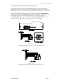
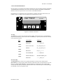
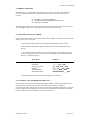
3.2.5 INTERFACE CONNECTORS
Two interface connectors are supplied on the standard CONTROL UNIT: the TRANSDUCER
INTERFACE CONNECTOR and the COMMUNICATIONS OUTPUT CONNECTOR. Both
connectors are located on the bottom of the CONTROL UNIT ENCLOSURE, as shown in
FIGURE 3.2.5.
The TRANSDUCER INTERFACE CONNECTOR is an eight-pin male connector, used to
interface the CONTROL UNIT to the TRANSDUCER. Refer to SECTION 3.3 for complete
details on the TRANSDUCER INTERFACE.
The COMMUNICATIONS OUTPUT CONNECTOR is a four-pin male connector, that provides
serial data to the remote display. If the CONTROL UNIT is configured for RS232 output, the data
can interface to an external computer or PLC.
Both connectors and their pinout definitions are defined in Table 3.2.5
1
COMMUNICATIONS INTERFACE
CONNECTOR
4
TRANSDUCER INTERFACE
CONNECTOR
1
8
Figure 3.2.5 Bottom view of PLS801
COMMUNICATIONS CONNECTOR
Pin 1
GROUND
Pin 2
RD
Pin 3
TD
Pin 4
CTL1
TRANSDUCER INTERFACE CONNECTOR
Pin 1
No connection
Pin 2
No connection
Pin 3
S1 (stator 1)
Pin 4
S3 (stator 3)
Pin 5
S4 (stator 4)
Pin 6
S2 (stator 2)
Pin 7
R2 (rotor 2)
Pin 8
R1 (rotor 1)
Table 3.2.5 Wiring designations for Communications and Transducer Interface connectors
Document #11609
Page - 5
PLS-801 User's Manual
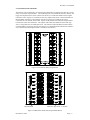
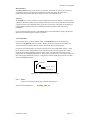
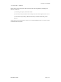
3.2.6 PLS-801 OUTPUT BOARD
The PLS-801 can be interfaced to an external output board that is equipped with either dry contact
relays or solid state output modules. The LOBE setpoints stored within the PLS-801 memory will
trigger the output board to activate or deactivate the relays or solid state modules as the angular
transducer rotates. Figure 3.2.6A illustrates the relay output board and its connection definitions.
Both normally closed (NC) and normally open (NO) contacts are available at the output
connectors for each channel of this board. Figure 3.2.6B illustrates the solid state output module
board and its connection definitions. The outputs of the solid state module are fused with type
2AG, 3.5Amp mini fuses for added protection. The solid state output module board also utilizes
on board LEDS to signify the status of each channel. An illuminated LED indicates the channel is
active and the associated output module is switched to the ON state.
Figure 3.2.6A PLS-801 Relay Output Board
Channel LEDS
Mini Fuse Type 2AG 3.5 A 250V
Figure 3.2.6B PLS-801 Solid State Output Module Board
Document #11609
Page - 6
PLS-801 User's Manual
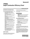
3.3 TRANSDUCER/CONTROL UNIT INTERFACE CABLE
The CONTROL UNIT is interfaced to the TRANSDUCER via a custom made transducer
interface cable. This cable is a 3-pair, individually shielded pairs, which contains an eight pin
female plug-connector on one end, and a seven pin female MS-type connector on the other end.
The standard transducer interface cable is wired at the factory to provide an INCREASING
angular position reading for CLOCKWISE rotation of the TRANSDUCER shaft (when looking
into the END of the shaft). The wiring diagram for this cable is shown in Figure 3.3A.
If an INCREASING angular position reading for COUNTER CLOCKWISE rotation of the
TRANSDUCER shaft is desired, refer to Figure 3.3B for this wiring diagram.
Figure 3.3A
Standard Wiring Diagram (Clockwise transducer shaft rotation)
Figure 3.3B
Wiring Diagram (Counter clockwise transducer shaft rotation)
Document #11609
Page - 7
PLS-801 User's Manual
4.0 USING THE PLS-801
It is strongly recommended that this User's Manual be read in its entirety before placing your PLS801 into operation. Failure to follow the instructions given in this User's Manual may void your
PLS-801 warranty.
4.1 INSTALLATION
ALL PLS-801 ELECTRICAL CONNECTORS MUST CONFORM WITH THE NATIONAL
ELECTRIC CODE AND ANY LOCAL ELECTRIC CODES IN EFFECT.
IN THE CASE OF ANY DISCREPANCIES BETWEEN THE ELECTRIC CODES AND THESE
INSTALLATION INSTRUCTIONS, THE ELECTRIC CODE MUST TAKE PRECEDENT.
4.1.1 MOUNTING THE TRANSDUCER
The TRANSDUCER is designed to be mounted on the target machine, and coupled to the target
machine shaft. The TRANSDUCER should be mounted and coupled in a manner such as to
minimize shock, vibration, as well as axial and radial shaft loading.
The TRANSDUCER may be mounted via the standard front face mount or the optional foot-type
mounting adapter.
4.1.2 MOUNTING THE CONTROL UNIT
The PLS-801 Control Unit is designed to be mounted in a NEMA type enclosure, which is suitable
for the ambient environment. The enclosure must protect the Control Unit from contamination
caused by water, oil, dust, or corrosive gases. The Control Unit should not be subjected to
excessive amount of mechanical shock or vibration.
The mounting location should be chosen such as to avoid exposure to significant levels of
electromagnetic interference (EMI), which can be induced by devices such as motor starters and
control relays. The operating temperature must be maintained between 32°F and 125°F.
4.1.3 CONNECTING THE TRANSDUCER TO THE CONTROL UNIT
The Transducer is connected to the PLS-801 Control Unit via the Transducer/Control Unit
Interface Cable. The Cable is a 3-pair, individually shielded pairs, containing an eight pin female
plug-connector on one end, and a seven pin female MS-type connector on the other.
The standard Interface Cable is wired at the factory to provide an INCREASING angular position
reading for CLOCKWISE rotation of the Transducer shaft (when looking into the END of the
shaft). An INCREASING angular position reading during COUNTERCLOCKWISE rotation of
the Transducer shaft may be achieved by interchanging two of the wires that are brought into the
eight pin female connector. See SECTION 3.3 for complete wiring details.
The Interface Cable may be a maximum length of 2500 feet, and should always be routed in such
a manner as to avoid exposure to electromagnetic interference (EMI).
Document #11609
Page - 8
PLS-801 User's Manual
4.1.3 CONNECTING THE TRANSDUCER TO THE CONTROL UNIT - Continued
The seven pin female MS-connector is plugged into the mating seven pin male connector located
on the rear of the Transducer.
The eight pin female connector is plugged into the mating eight pin male connector located on the
bottom of the PLS-801 Control Unit (See SECTION 3.3).
4.1.4 INSTALLING THE AC POWER CORD
An AC Power Cord is provided with each PLS-801 Control Unit. The female end of the Power
Cord should be inserted into the male AC Power Plug located on the side of the Control Unit
enclosure.
4.1.5 POWERING ON THE CONTROL UNIT
The Control Unit requires a clean, stable source of AC Power to operate. See SECTION 3.2 for
the complete AC Power requirements and specifications of the various Control Unit input power
options.
The male end of the AC Power Cord should be inserted into a standard GROUNDING
RECEPTACLE, which has been wired to provide the AC Power requirements specified in
SECTION 3.2.
Document #11609
Page - 9
PLS-801 User's Manual
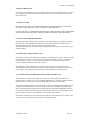
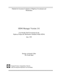
4.2 PLS-801 PROGRAMMING
PLS-801 offers six standard FUNCTIONS: POSITION, SCALE FACTOR, OFFSET, SETPOINT,
TACHOMETER and MOTION. The SCALE FACTOR, OFFSET, SETPOINT and MOTION
DETECT functions require the user to enter data via the FRONT PANEL.
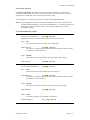
Programming is accomplished via four tactile-feel keys: NEXT, INCrement, DECrement, and
ENTER. Figure 4.2 depicts the front panel layout of the PLS-801 overlay.
T
programmable
l imit
s w it c h
NEXT
INC
DEC
+
P L S - 8 01
ENTER
Figure 4.2 PLS-801 Front Panel
Next Key
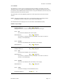
The NEXT key is used to select the desired FUNCTION. Following Power On, the POSITION
function is automatically selected. Each time the NEXT key is pressed, the functions are selected
in the following sequence:
KEY
FUNCTION
DISPLAY
POSITION
-------_POS_375
SCALE FACTOR
SF_1000_POS_375
OFFSET
OF__454_POS_375
SETPOINT
CH_01__F -T
TACHOMETER
--------RPM 050
MOTION DETECT
MF020T050RPM_050
POSITION
-------_POS_375
NEXT
NEXT
NEXT
NEXT
NEXT
NEXT
INCrement Key
The INCrement key is used to set a specific data field to its desired value. Each time the
INCrement key is pressed and quickly released, the data field value is incremented by one count.
However, when the INCrement key is pressed and held in, the data field value will be rapidly
incremented until the key is released. Each data field value is automatically incremented through
its minimum value to its maximum value.
Document #11609
Page - 10
PLS-801 User's Manual
DECrement Key
The DECrement key may also be used to set a specific data field to its desired value. However,
the data field value will be decremented rather than incremented. Each data field value is
automatically decremented through its maximum value to its minimum value.
Enter Key
The ENTER key is used to enter the currently displayed data field into memory. The INCrement
and DECrement keys modify only the displayed data field - they do not modify the stored data that
is actually used by the CONTROL UNIT. In general, an asterisk (*) will appear on the display to
indicate that the displayed data value is different from the stored data value, and must be
ENTERED.
For each of the PLS-801 functions, a BLINKING digit on the alphanumeric display specifies the
data field at which data may be entered or modified.
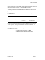
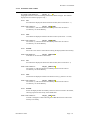
4.2.1 POSITION
Upon applying power to the CONTROL UNIT, the POSITION function is automatically
selected. The POSITION function is used to display the transducer shaft position (POS), the
status of each of the Channel Outputs, and the status of the Motion Detect Output.
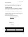
Each of the 16 Channel Outputs is assigned a status location on the POSITION display. A solid
block character in the corresponding location indicates that the Channel Output is ON, while a
blank character indicates that the Channel Output is OFF. The Channel Output status is also
displayed by the TACHOMETER function. Keep in mind that data entry is not allowed while the
PLS in displaying POSITION. Figure 4.2.1 depicts the channel output status locations viewable
during the POSITION display.
Channel 1
- - - - - - - -_POS_969
Channel 16
Figure 4.2.1 Channel Output Status Locations
Select: NEXT
Advances the display to the SCALE FACTOR (SF) function.
SCALE FACTOR DISPLAY:
Document #11609
SF_1000_ _POS_375
Page - 11
PLS-801 User's Manual
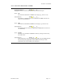
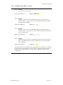
4.2.2 SCALE FACTOR
The SCALE FACTOR is the number of increments that the CONTROL UNIT divides one
complete TRANSDUCER shaft rotation into. The SCALE function allows the user to enter a 4
digit SCALE FACTOR (SF) value in the range from 0002 to 1000.
The SCALE function also displays the current Transducer shaft POSITION (POS).
NOTE: Upon changing the SCALE FACTOR, the CONTROL UNIT will re-scale the current
transducer shaft POSITION, as well as all stored LOBE data. Care should be taken when
changing the SCALE FACTOR, as the re-scaling of the LOBE data may produce
undesirable rounding.
SCALE FACTOR setup example:
SCALE FACTOR DISPLAY:
SF_1000_ _POS_375
(Highlighted character indicates blinking character that can be changed)
Select: INC
Increments the SCALE FACTOR value on the display.
NEW DISPLAY:
SF_0002_ _POS*375
The asterisk (*) indicates that the new SCALE FACTOR value must be stored
into memory via the ENTER key.
Select: ENTER
Stores the new SCALE FACTOR value into memory on the display.
NEW DISPLAY:
SF_0002_ _POS_375
SCALE FACTOR DISPLAY:
SF_0002_ _POS_375
Select: DEC
Decrements the SCALE FACTOR value on the display.
NEW DISPLAY:
SF_1000_ _POS*375
The asterisk (*) indicates that the new SCALE FACTOR value must be stored
into memory via the ENTER key.
Select: ENTER
Stores the new SCALE FACTOR value into memory on the display.
NEW DISPLAY:
SF_1000_ _POS_375
Select: NEXT
Advances the display to the OFFSET (OF) function.
OFFSET DISPLAY:
Document #11609
OF_ _453_ _POS_375
Page - 12
PLS-801 User's Manual
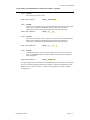
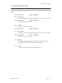
4.2.3 OFFSET
The OFFSET is a constant, positive adjustment that the CONTROL UNIT adds to the actual
Transducer position to produce the shaft POSITION which is displayed and used by the Control
Unit functions. The OFFSET function allows the user to align the Transducer (electrical zero) and
machine (mechanical zero) reference points.
The permissible value of the OFFSET parameter is in the range from 0 to the FULL SCALE
VALUE.
NOTE: Changing the OFFSET value causes a corresponding change in the displayed shaft
POSITION, but does not affect the values of the stored LOBE data.
The OFFSET function also displays the current Transducer shaft POSITION (POS).
OFFSET setup example:
OFFSET DISPLAY:
OF_ _453_ _POS_375
(Highlighted character indicates blinking character that can be changed)
Select: INC
Increments the OFFSET value on the display.
NEW DISPLAY:
OF_ _454_ _POS*375
The asterisk (*) indicates that the new OFFSET value must be stored into
memory via the ENTER key.
Select: ENTER
Stores the new OFFSET value into memory on the display.
NEW DISPLAY:
OF_ _454_ _POS_375
OFFSET DISPLAY:
OF_ _454_ _POS_375
Select: DEC
Decrements the OFFSET value on the display.
NEW DISPLAY:
OF _ _453_ _POS*375
The asterisk (*) indicates that the new OFFSET value must be stored into
memory via the ENTER key.
Select: ENTER
Stores the new OFFSET value into memory on the display.
NEW DISPLAY:
OF _ _453_ _POS_375
Select: NEXT
Advances the display to the SETPOINT function.
SETPOINT DISPLAY:
Document #11609
CH_01_ _F_ _ _-T_ _ _
Page - 13
PLS-801 User's Manual
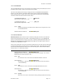
4.2.4 SETPOINT
The SETPOINT is used to enter new LOBE data into the CONTROL UNIT memory, as well as to
display or modify currently stored LOBE data. SETPOINT allows single or multiple LOBES to be
entered on any or all of the 16 Channels. A total of 238 LOBES may be entered.
The TIMING and the DWELL of each LOBE is defined by a FROM position and a TO position.
The FROM position defines the TIMING, whereas the difference between the FROM and TO
positions defines the DWELL.
The SETPOINT function displays three data fields: CHANNEL NUMBER (CH), FROM position
(F), and TO position (T).
FUNCTION
DISPLAY
FIELD
RANGE
SETPOINT
CH_01_F010-T050
'CH'CHANNEL
'F' FROM Position
'T' TO Position
NUMBER 08, 12 OR 16
000 to Scale Factor-1
000 to Scale Factor-1
PLS-801 allows 'programming through zero', by specifying a FROM field that is larger than the
TO field. For example, if the FROM field is specified as '300' and the TO field as '060', the
Channel output will turn 'ON' at position '300', remain 'ON' through '000', and be turned 'OFF' at
'060'.
Complete details of the various operations that can be performed via the SETPOINT function are
given in the following sections:
4.2.4.A
4.2.4.B
4.2.4.C
4.2.4.D
Document #11609
SELECTING THE CHANNEL NUMBER
DISPLAYING/MODIFYING EXISTING LOBES
ENTERING NEW LOBES
DELETING EXISTING LOBES
Page - 14
PLS-801 User's Manual
4.2.4.A SELECTING THE CHANNEL NUMBER
SETPOINT DISPLAY:
CH_01_ _F_ _ _-T_ _ _
(Highlighted character indicates blinking character that can be changed)
Select: INC
Increments the CHANNEL NUMBER on the display (e.g. from 01 to 02).
NEW DISPLAY:
CH*02_ _F_ _ _-T_ _ _
The asterisk (*) indicates that the new CHANNEL NUMBER value must be
entered via the ENTER key.
Select: DEC
Decrements the CHANNEL NUMBER on the display (e.g. from 02 to 01).
NEW DISPLAY:
CH*01_ _F_ _ _-T_ _ _
The asterisk indicates that the new CHANNEL NUMBER must be entered via
the ENTER key.
Select: ENTER
Stores the new CHANNEL NUMBER into memory and begins the data entry
for LOBE values.
NEW DISPLAY:
CH_01_ _F_ _ _-T_ _ _
If the LOBE data for the F and T fields contains data, then the LOBE parameter
has previously been programmed. If the LOBE has not been previously
programmed, then only DASHES will be displayed.
Document #11609
Page - 15
PLS-801 User's Manual
4.2.4.B DISPLAYING/MODIFYING EXISTING LOBES
SET EXISTING
LOBE DISPLAY:
CH_01_ _F010-T050
(Highlighted character indicates blinking character that can be changed. The numbers
displayed are for reference purposes only.)
Select: INC
Increments the displayed F field to the desired value (e.g. from 010 to 011)
NEW LOBE DISPLAY:
CH_01_ _F011*T050
The asterisk (*) indicates that the new FROM position must be entered
into memory via the ENTER key.
Select: DEC
Decrements the displayed F field to the desired value (e.g. from 011 to 010)
NEW LOBE DISPLAY:
CH_01_ _F010*T050
The asterisk (*) indicates that the new FROM position must be entered
into memory via the ENTER key.
Select
ENTER
Moves the cursor to the T field without entering the displayed data into memory.
NEW LOBE DISPLAY:
CH_01_ _F010*T050
Lobe data can be entered into the T field.
Select: INC
Increments the displayed T field to the desired value (e.g. from 050 to 051)
NEW LOBE DISPLAY:
CH_01_ _F010*T051
The asterisk (*) indicates that the new FROM position must be entered
into memory via the ENTER key.
Select: DEC
Decrements the displayed T field to the desired value (e.g. from 051 to 050)
NEW LOBE DISPLAY:
CH_01_ _F010*T050
The asterisk (*) indicates that the new FROM position must be entered
into memory via the ENTER key.
Select: ENTER
Enters the displayed data into memory and moves the cursor back to the F field,
allowing inspection of the newly stored LOBE data.
NEW LOBE DISPLAY:
CH_01_ _F010-T050
Asterisk is changed to a dash indicating the LOBE data has been entered into
memory successfully.
Document #11609
Page - 16
PLS-801 User's Manual
4.2.4.B DISPLAYING/MODIFYING EXISTING LOBES - Continued
Select: ENTER
Moves the cursor to the T field
NEW LOBE DISPLAY:
CH_01_ _F010-T050
Select: ENTER
Moves the cursor to the F field. If the F and T fields contain no data other than
dashes, then no additional LOBE data has been entered for Channel 01.
Otherwise the next active LOBE is displayed for the selected channel.
NEW LOBE DISPLAY:
CH_01_ _F_ _ _-T_ _ _
Select: ENTER
Moves the cursor to the T field. If the F and T fields contain no data other than
dashes, then no additional LOBE data has been entered for Channel 01.
Otherwise the next active LOBE is displayed for the selected channel.
NEW LOBE DISPLAY:
CH_01_ _F_ _ _-T_ _ _
Select: ENTER
Automatically selects the next Channel Number and moves the cursor to the F
field . The FROM/TO data for the first LOBE of the newly selected channel
will be displayed.
NEW LOBE DISPLAY:
CH_02_ _F038-T126
You may program up to a maximum of 238 LOBES and up to a maximum of 16 channels
if your unit has been equipped with the extra channels. Standard configurations for the
PLS801 are 8, 12, and 16 channels. Contact Toledo Transducers for other available
configurations.
Document #11609
Page - 17
PLS-801 User's Manual
4.2.4.C ENTERING NEW LOBES
SET NEW LOBE DISPLAY:
CH_01_ _F_ _ _-T_ _ _
(Highlighted character indicates blinking character that can be changed. The numbers
displayed are for reference purposes only.)
Select: INC
Increments the displayed F field to the desired value (000 to scale factor - 1)
NEW LOBE DISPLAY:
CH_01_ _F081*T000
The asterisk (*) indicates that the new FROM position must be entered
into memory via the ENTER key.
Select: DEC
Decrements the displayed F field to the desired value (scale factor -1 to 000)
NEW LOBE DISPLAY:
CH_01_ _F080*T000
The asterisk (*) indicates that the new FROM position must be entered
into memory via the ENTER key.
Select
ENTER
Moves the cursor to the T field without entering the displayed data into memory.
NEW LOBE DISPLAY:
CH_01_ _F080*T000
Lobe data can be entered into the T field.
Select: INC
Increments the displayed T field to the desired value (000 to scale factor -1)
NEW LOBE DISPLAY:
CH_01_ _F080*T196
The asterisk (*) indicates that the new FROM position must be entered
into memory via the ENTER key.
Select: DEC
Decrements the displayed T field to the desired value (e.g. from 051 to 050)
NEW LOBE DISPLAY:
CH_01_ _F080*T195
The asterisk (*) indicates that the new FROM position must be entered
into memory via the ENTER key.
Select: ENTER
Enters the displayed data into memory and moves the cursor back to the F field,
allowing inspection of the newly stored LOBE data.
NEW LOBE DISPLAY:
CH_01_ _F080-T195
Asterisk is changed to a dash indicating the LOBE data has been entered into
memory successfully.
Document #11609
Page - 18
PLS-801 User's Manual
4.2.4.C ENTERING NEW LOBES - Continued
Select: ENTER
Moves the cursor to the T field
NEW LOBE DISPLAY:
CH_01_ _F080-T195
Select: ENTER
Moves the cursor to the F field and displays the next active LOBE for the
selected channel. You may choose to enter additional LOBES for the FROM
field of the selected channel.
NEW LOBE DISPLAY:
CH_01_ _F_ _ _-T_ _ _
Select: ENTER
Moves the cursor to the T field and displays the next active LOBE for the
selected channel. You may choose to enter additional LOBES for the TO field
of the selected channel.
NEW LOBE DISPLAY:
CH_01_ _F_ _ _-T_ _ _
Select: ENTER
Automatically selects the next Channel Number and moves the cursor to the F
field . The FROM/TO data for the first LOBE of the newly selected channel
will be displayed.
NEW LOBE DISPLAY:
CH_02_ _F_ _ _-T_ _ _
You may program up to a maximum of 238 LOBES and up to a maximum of 16 channels
if your unit has been equipped with the extra channels. Standard configurations for the
PLS801 are 8, 12, and 16 channels. Contact Toledo Transducers for other available
configurations.
Document #11609
Page - 19
PLS-801 User's Manual
4.2.4.D DELETING EXISTING LOBES
To delete an existing LOBE, use the increment or decrement keys to set the F and T fields to the
same value. Upon entering a LOBE with the same F and T values, the LOBE will be deleted from
memory.
SETPOINT DISPLAY:
CH_01_ _F080-T195
Select: INC or DEC
Increments or decrements the displayed F field to the same value as the T field.
NEW LOBE DISPLAY:
CH_01_ _F195-T195
F fields and T fields are the same.
Select: ENTER
The cursor advances to the T field.
SETPOINT DISPLAY:
CH_01_ _F080-T195
Select: INC or DEC
Increments or decrements the displayed T field to the same value as the F field.
NEW LOBE DISPLAY:
CH_01_ _F080-T080
F fields and T fields are the same.
Select: ENTER
The LOBE is deleted from memory if the F field and T field were the same.
An empty LOBE is indicated as dashes in the F and T fields.
Select: NEXT
Advances the display to the Tachometer (RPM) function.
Document #11609
Page - 20
PLS-801 User's Manual
4.2.5 TACHOMETER
The TACHOMETER function is used to display the Transducer shaft speed in RPM, the status of
the Motion Detect Output, and the status of the Channel Outputs.
The status of the Motion Detect Output is displayed in the TACHOMETER and POSITION
functions. An "M" character in the Motion Detect status location indicates that shaft RPM is
within the Motion Detect window (ON), while a blank character indicates that the shaft RPM
value falls outside of the Motion Detect window (OFF).
TACHOMETER DISPLAY:
- - - - - - - - MRPM_010
(Motion Detect Output Status = ON)
TACHOMETER DISPLAY:
- - - - - - - - _RPM_010
(Motion Detect Output Status = OFF)
Select: NEXT
Advances the display to the Motion Detect (MF) function and places the cursor
into the MF data field.
MOTION DETECT DISPLAY:
MF020 T040RPM_010
4.2.6 MOTION DETECT
MOTION DETECT allows the user to set a window for shaft speed, and receive an indication
that the shaft speed falls within the window via the POSITION function, the TACHOMETER
function, and the Motion Detect output. The window is defined by MOTION FROM ('MF') and
MOTION TO ('MT') RPM values. SHAFT RPM values EQUAL to the 'MF' or 'MT' values are
considered to be WITHIN the window.
NOTE: If the 'MF' field is less that the 'MT' field, the MD status will be 'ON' when the shaft speed
is within the MD window, and 'OFF' when it is outside of the window. If the 'MF' field is greater
than the 'MT' field, the MD status will be 'OFF' when the shaft speed is within the MD window,
and 'ON' when it is outside of the window.
MOTION DETECT DISPLAY:
MF020 T040RPM_010
(Highlighted character indicates blinking character that can be changed. The numbers
displayed are for reference purposes only.)
Select: INC
Increments the value in the F field of the MOTION DETECT function.
NEW DISPLAY:
MF021 T040RPM*010
The asterisk (*) indicates that the new MF value must be stored into memory
via the ENTER key.
Select: DEC
Decrements the value in the F field of the MOTION DETECT function.
NEW DISPLAY:
MF020 T040RPM*010
The asterisk (*) indicates that the new MF value must be stored into memory
via the ENTER key.
Select: ENTER
Moves the cursor to the T field without entering the displayed data into memory.
Document #11609
Page - 21
PLS-801 User's Manual
4.2.6 MOTION DETECT - Continued
NEW DISPLAY:
MF020T040RPM*010
Select: INC
Increments the value in the T field of the MOTION DETECT function.
NEW DISPLAY:
MF021T040RPM*010
The asterisk (*) indicates that the new MT value must be stored into memory
via the ENTER key.
Select: DEC
Decrements the value in the T field of the MOTION DETECT function.
NEW DISPLAY:
MF020T040RPM*010
The asterisk (*) indicates that the new MT value must be stored into memory
via the ENTER key.
Select: ENTER
Enters the displayed data into memory and moves the cursor back to the F field,
allowing inspection of the newly stored MOTION DETECT data.
NEW DISPLAY:
MF020 T040RPM_010
Select: NEXT
Advances the display to the POSITION (POS) function. This is the data display
used to indicate resolver position and output relay status.
NEW DISPLAY:
Document #11609
- - - - - - - -_POS_969
Page - 22
PLS-801 User's Manual
4.3 ERROR CONDITIONS
The ERR Output on the PLS-801 Output Board (see section 3.2.6 for details) can be used to
provide a hardware indication that one of the following Control Unit error conditions has
occurred:
q
q
q
TRANSDUCER SIGNAL ERROR
CONTROL UNIT MICROPROCESSOR FAULT
LOSS OF AC POWER
The ERR Output is held ON by the Control Unit hardware. Should any of the Control Unit errors
occur, the ERR Output will be turned OFF to indicate an error condition exist.
4.3.1 TRANSDUCER SIGNAL ERROR
If any of the Interface Cable wires become disconnected or broken, the following error indications
will be given by the Control unit:
1) The Channel Outputs, Motion Detect Output and ERR Output will be set low
2) The Channel Output Relays, Motion Detect Relay and Fault Check Relay will be
opened.
3) An error message will be placed on the front panel display (if attached), when any
of the following functions are selected: (No error message is given if the SETPOINT
function is currently selected.)
FUNCTION
DISPLAY
POSITION
SCALE FACTOR
OFFSET
TACHOMETER
MOTION DETECT
--------__POS__ERR
SF__1000__POS__ERR
OF___434___POS__ERR
--------___RPM__ERR
MF020T040RPM____ERR
4) Normal programming will be allowed during this error condition
4.3.2 CONTROL UNIT MICROPROCESSOR FAULT
In the event of a microprocessor fault, the alphanumeric display, Channel Output and Channel
Output Relays are frozen in the state that existed at the time of the fault. Because a
microprocessor fault is detected by the Control Unit hardware, the Fault Check Relay can be used
to give an indication that a fault has occurred. The Fault Check Relay will be held closed during
normal operation, and will be opened by a microprocessor fault.
Document #11609
Page - 23
PLS-801 User's Manual
4.3.3 LOSS OF AC POWER
In the event of a loss of AC power, the Control Unit will cease all operations, resulting in the
following conditions:
1) The front panel display will become blank
2) The Channel Outputs, Motion Detect Output and Fault Check Outputs will be set low
3) The Channel Output Relays, Motion Detect Relay and Fault Check Relay will be
opened.
NOTE: Because the program data is stored in non-volatile EEPROM memory, it will not be lost as
a result of a loss of AC power.
Document #11609
Page - 24