1
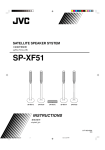
pH-Measure
Channel 1
Standardize
12.000
XL15
Measure
STABLE
Mode
Last Standardization :7 Mar 2004 / 4:06:37 PM
Buffer Group :USA
Setup
> Touch standardize icon to access standardiztion mode
Print
Show Graph
Log Data
Profile
Sample ID :
User ID
---
: Default
Temp. : 25.5 C (ATC)
mV Manual
: -295.7
USER
Auto Buffer : ON
Slope
: 102.8%
Auto Read : OFF
Offset
: -32.4 mV
Home
Logoff
?
Help
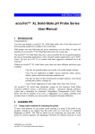
XL15
USER Manual
Table of Contents
Introduction..................................................................................................3
Unpacking the Meter ....................................................................................4
Specifications ...............................................................................................5
Getting Started
CONNECTORS...............................................................................................................6
pH ELECTRODES .........................................................................................................7-8
Using the Meter
TOUCH SCREEN OPERATIONS ..................................................................................9-10
Using the STYLUS..........................................................................................................11
Setting TIME and DATE..................................................................................................12
ON-SCREEN KEYBOARD ..............................................................................................13
EXPANSION CARD ......................................................................................................14
Connecting to the INTERNET..........................................................................................15
Choosing a CHANNEL .................................................................................................16
BUTTON FUNCTIONS . ...........................................................................................17-18
pH Setup
pH SETUP SCREEN and Function Buttons ........................................................................19
Access pH SETUP ..........................................................................................................20
Set SAMPLE ID#............................................................................................................21
Select BUFFER GROUP ..................................................................................................22
Select BUFFER RECOGNITION.......................................................................................23
Select AUTO READ MODE ...........................................................................................24
Set pH STABILITY CRITERIA ............................................................................................25
Set DEFAULT TEMPERATURE ..........................................................................................26
Set ISOPOTENTIAL POINT ............................................................................................27
Set ALARM LIMITS.........................................................................................................28
Set PRINT CRITERIA.......................................................................................................29
Set DATA STORAGE CRITERIA .......................................................................................30
Set DISPLAY CRITERIA SETUP .........................................................................................31
View STORED DATA ................................................................................................32-33
mV Setup
mV SETUP SCREEN and Function Buttons .......................................................................34
Access mV SETUP .........................................................................................................35
Set SAMPLE ID#............................................................................................................36
Set ALARM LIMITS.........................................................................................................37
Set PRINT CRITERIA SETUP ...........................................................................................38
Set DATA STORAGE CRITERIA .......................................................................................39
Set DISPLAY CRITERIA ...................................................................................................40
View STORED DATA ................................................................................................41-42
pH Operation
STANDARDIZING ...................................................................................................44-48
With Auto Buffer Recognition ................................................................................44-45
With Manual Buffer Recognition ............................................................................46-47
TEMPERATURE STANDARDATION..................................................................................48
pH MEASUREMENT .................................................................................................49-50
With Auto Read ON and OFF ....................................................................................50
mV Operation
mV MEASUREMENT ................................................................................................51-53
Absolute mV Measurement .........................................................................................52
Relative mV Standardization and Measurement ...........................................................52
Cleaning.....................................................................................................54
Trouble Shooting ........................................................................................55
Warranty ...................................................................................................56
Compliance ................................................................................................57
Appendix
Determining ISOPOTENTIAL POINTS EXPERIMENTALLY ..................................................58
Factory DEFAULT SETTINGS ..........................................................................................59
pH THEORY.............................................................................................................60-64
Replacement Parts......................................................................................65
2
Introduction
Thank you for selecting a Fisher Scientific accumet pH meter. This manual describes
the operation of the accumet XL15 meter. The state-of-the art meter that you have
purchased runs on a Windows CE platform and has a similar framework of a pocket
PC ( or "Palm Pilot"). It is easy to operate and will guide you through the various
functions by displaying easy to understand prompts. This operating manual should
answer any questions that might arise in operating your meter; however, do not hesitate to call our accumet Technical Support Hotline at 1-888-358-4706, if you need
any assistance.
This meter is designed to provide all the information necessary to guide you through
the process of measuring pH or mV with a series of prompts on the screen. The accumet excel XL15 provides microprocessor precision in a compact benchtop design
that is easy to use. One touch screen controls all procedures, letting you:
• Measure pH, absolute mV, relative mV or pH (FET)
• Select one of three sets of standard buffer groups
• Implement automatic buffer recognition
• Standardize with up to five standard or customer buffers
• Customize your display screen and operating parameters
• Assign operator and sample identification numbers
• Store 1000 data points per user in the meter’s memory or transfer data to a
computer or printer.
• Access extensive online help with just a touch a button
It all adds up to rapid, completely automatic, intuitive operation.
Useful tips will appear in this
box throughout this manual
3
Unpacking the Meter
The following is a listing of what you should have received with your new accumet XL15
pH/mV meter.
Meter with kit includes
meter
power supply
electrode arm support bracket
electrode arm
electrode (13-620-130)
ATC probe (13-620-19)
manual and literature
Meter only includes
meter
power supply
electrode arm support bracket
manual and literature
If any of these items are missing, please contact the accumet Technical Support Hotline at
1-888-358-4706. Accessory Conductivity Probes and Ion Selective Electrodes are available
and can be ordered by calling Fisher Customer Service at 800/766-7000.
4
Specifications
Display
screen size
menu options
help screens
configurable display
keypad controls
Memory
internal diagnostics
programmable data storage
programmable data output
print interval
programmable alarm
1000 data pts
yes
store on stable, time, manual
output on stable, time, manual
1 to 86400 sec
yes
range
resolution
relative accuracy
automatic buffer recognition
manual buffer recognition
calibration points
auto lock
FET
-2.000 to 20.000
0.1/0.01/0.001
± 0.002
yes
yes
5
yes
yes
pH Mode
mV Mode
Temperature Mode
General
640x480 digit LCD
4 1/2” x 6”
extensive
extensive
yes
context specific touchscreen
range
resolution
accuracy
± 2000.0
0.1
± 0.2
range
resolution
accuracy
-5.0 to +105.0 °C
0.1 °C
± 0.2 °C
inputs/outputs
electrical requirements
output from PSU
line voltage tolerance
input impedance
meter size
meter weight
BNC, Pin, ATC, RS232, DIN (for FET)
115 V/60 Hz, 230 V/50 Hz
9VDC, 3.3A center negative
± 10%
>10 12 ohms
6.75"x9.25"x3.5"
2.8 lb.
Operating Conditions
operating temperature
operation humidity
maximum operating altitude
installation category
Pollution category degree
5-45 °C
5-80 % noncondensing
2000m
II
2
5
CONNECTORS
Getting Started
1
Review the layout and arrangement of the rear connector panel.
accuFET pH electrode
(Channel 3)
Stylus
Power
Automatic Temperature
Compensation (ATC)
RJ 45
USB
Ver 1.1
POWER
RJ 45
USB
USB-A,
Ver 1.1
twin port*
FET
USB-A
Reference pin jack
BNC input connector
(Channel 1)
ATC1
REF1
pH1
9V
CENTER
GND
SD CARD
IrDA
RS-232
Infrared communication
SD card reader
RS-232 (computer/printer)
2
3
*NOTE: USB devices like printer, mouse, etc.
should be connected to the lower port (USB-A).
Connect the electrode
arm to the base.
Connect the power
cable to the rear
connector panel power
jack and to a power
source.
POWER
9V
CENTER
GND
6
pH ELECTRODES
Getting Started
This meter allows you to use two types of pH electrodes: the conventional glass pH
electrode and the AccuFET field effect transistor (FET) pH electrode.
1
Carefully remove the protective cover
from the end of the electrode. Before
first using your glass pH electrode, or
whenever the electrode is dry, soak it
2-4 hours in an electrode storage
solution, pH 4 Buffer, or KCl solution.
shorting
cap
2
Remove the shorting cap on BNC connector.
Connect the combination pH electrode by
plugging it into the BNC input connector
(twisting to lock in place).
If a combination electrode isn’t used, connect
the indicating pH electrode into the BNC
input connector. Plug the reference electrode into the reference pin jack. Also, install
the ATC probe into the ATC jack.
Note: Be sure to connect all probes to the
appropriate channel connectors (for example: Input 1, Ref 1 and ATC1).
Do not discard the
BNC shorting cap.
Option: Connect the optional AccuFET electrode by plugging it into the FET jack on the
back meter panel. Allow the AccuFET to warm
up five minutes before use.
If both a conventional electrode
and an AccuFET electrode are
connected to the meter, do not put
them in a solution together
because you will get inaccurate
measurements.
7
Getting Started
pH ELECTRODES
3
4
Rinse and blot-dry (don't wipe) electrodes between each measurement.
Rinse electrodes with distilled or
deionized water, or a portion of the
next solution to be measured.
Between measurements, store conventional pH electrodes in electrode
storage solution, pH 4 buffer, or KCl
solution. Always leave the filling hole
of liquid filled combination electrodes
open. Refill when the level of solution
gets below the manufacturer's recommended level.
Proper electrode care is fundamental to obtaining reliable pH measurements. Improper care of the electrode may cause the meter reading to
drift, respond slowly, or produce erroneous readings. For this reason,
the electrode should always be conditioned and used in accordance
with manufacturer’s instructions.
8
TOUCH SCREEN OPERATION
Using the Meter
When the meter is turned on it first goes though self test, displays the FISHER Catalog
cover, briefly displays the desktop screen (Home) before loading the XL15 program
which results in the display of the measurement screen.
pH-Measure
Channel 1
Standardize
7.00
Measure
STABLE
Not standardized
Mode
Setup
My
Computer
Internet
Explorer
> Touch standardize icon to access standardiztion mode
Media Player
Show Graph
Print
Log Data
15
My
Documents
XL15
AdminUser
Profile
Sample ID :
User ID
Recycle Bin
---
: Default
Temp. : 25.5 C (ATC)
mV
: 0.0
Auto Buffer : ON
Slope
: ......
Auto Read : OFF
Offset
: ......
Home
XLESSLXLE
Logoff
®
Microsoft
?
ARM.
WindowsCE.net
Help
Desktop screen(Home)
pH measurement screen
9
Using the Meter
TOUCH SCREEN OPERATION
The new accumet XL15 benchtop pH meter operates with a state-of-the-art touch
screen. The touch screen makes this the easiest meter on the market to operate and
care for. When the meter is first plugged in, the meter runs a self-test and takes you
to the pH measurement screen. Touch any icon to access the functions of the meter.
Your XL15 meter also includes a stylus that you can use to tap on your screen. The
stylus easily stores inside the back panel of the meter.
The buttons on the right side of the screen control all of the functions of the meter. A
light touch on the screen is all that you need to access the various functions. Once
you touch a button you will get an audible tone; the screen will not change until
you lift your finger.
This design prevents rapid uncontrolled scrolling through the various function
screens. Function buttons and options change from screen to screen. Easy to understand prompts guide you through the operation of the meter in the selected mode. If
you are ever in doubt about what to do, just touch Help on the bottom right corner
of the screen for detailed information about that screen.
The touch screen is made of a durable polyester material that is chemically resistant.
Maintenance is simple with this meter. To clean the screen you just need to wipe it
with a damp cloth and dry it with a clean dry towel. For additional information, see
Cleaning and Troubleshooting sections of the manual.
10
Using the STYLUS
Using the Meter
Your XL15 Meter comes with a stylus that you should use to tap on your screen.
The stylus easily stores inside the back panel of the meter.
You can perform two basic actions using the stylus:
Tap
Lightly touch the screen to select or open an item. Lift the stylus after you tap an
item. Tapping is equivalent to clicking an item with the mouse on your personal
computer. Note: Some program items require a double tap to select or launch.
Double tap on the icons from the Desktop (Home) page and single click in the
XL15 application
Drag
Place the point of the stylus on the screen and drag an item across the screen without lifting the stylus until you have completed the selection. Dragging is equivalent to
dragging with the left mouse button pressed on your personal computer .
CAUTION: To prevent damage to your XL15 screen, never use any
device other than the stylus that comes with the meter or an approved
replacement to tap on the screen. Order extra or replacements if you
lose or break your stylus.
11
Using the Meter
Setting TIME and DATE
Setting the Time
1. From the HOME screen tap the bottom left of the screen to access the Start
menu. Tap Start > Settings > Control Panel. This launches the Control
Panel screen.
2. Double tap Date/Time icon. This launches the Date/Time Properties
window.
3. Tap the time-zone down arrow, and select the appropriate time zone.
4. Tap the hour, minutes, or seconds. Use up and down arrows to adjust.
5. Tap AM or PM. Use up and down arrow to select.
6. Tap Apply button.
7. Tap OK to save the time.
Setting the Date
1. From the HOME screen tap the bottom left of the screen to access the Start
menu. Tap Start > Settings > Control Panel. This launches the Control
Panel screen.
2. Double tap Date/Time icon. This launches the Date/Time Properties
window.
3. Tap the left or right arrow to select a month and year.
4. Tap a day.
5. Tap Apply button.
6. Tap OK to save the time.
You need to reset your time zone, time, and date if:
• The time changes or you are traveling to a different time zone.
OK X
Date/Time Properties
Date/Time
March 2004
S
29
7
14
21
28
4
M
1
8
15
22
29
5
T W T
2 3 4
9 10 11
16 17 18
23 24 25
30 31 1
6 7 8
F S
5 6
12 13
19 20
26 27
2 3
9 10
Current Time
4:05:27 PM
Time Zone
(GMT-06:00) Central Time (US & Canada)
Automatically adjust clock for daylight saving
Apply
_
The time on the meter can be synchronized with your personal computer
through Microsoft® "Active sync".
12
ON-SCREEN KEYBOARD
Using the Meter
Using the On-Screen Keyboard
Use the stylus to tap letters, numbers, and symbols on the on-screen keyboard to
enter typed text directly onto the screen.
1. From any application, screen tap the bottom right of the screen to access the
input panel. Tap the Pencil/Keyboard icon (see below). A pop-up menu will
appear.
2. Tap LargeKB to display a large keyboard with all function keys.
Tap keyboard for a basic function alphanumeric keyboard.
3. Tap desired letters, numbers and symbols on the keyboard. Hit the enter key.
4. To remove keyboard, tap on Pencil icon. The pop-up menu will appear. Tap
Hide Input Panel to remove keyboard.
5:25 PM
5:25 PM
To see symbols, tap the Shift key.
13
Using the Meter
EXPANSION CARD
Expansion Cards
You can expand the memory and connectivity of your XL15 meter.
Use optional expansion cards for:
• Expanding the memory of your XL15 meter
• Viewing the content of memory cards
Expansion cards must be purchased separately
and are not included with your XL15 meter
Installing an Expansion Card
To install a Secure Digital (SD) card into an expansion slot on the XL15 meter:
1. Locate the slot on the top of XL15 meter.
2. Remove the protective plastic card.
3. Insert the expansion card into the expansion slot and push the connection edge of
the card firmly into the expansion slot.
If your expansion card is not recognized, follow
the card manufacturer’s instructions to install it.
Removing a Secure Digital (SD) Expansion Card
1. Close all applications that are using the expansion card.
2. Remove a card from the Secure Digital expansion slot by slightly pushing down
on the card to unlock it.
3. When the card disengages and pops up, pull it from the expansion slot.
CAUTION: SD cards must first be unlocked
before removal.
Viewing the Content of Memory Cards
Use File Explorer to view the files that are located on your optional Secure Digital card.
1. From the Start menu, tap Programs > File Explorer.
2. Tap the root directory of My Device, and select the Storage Card folder (SDIO) to
see a list of files and folders.
14
Connecting to the INTERNET
Using the Meter
Entering an Internet Address
With Pocket Internet Explorer and a connection to the Internet, you can view Web sites
on your XL15 meter by typing an address or Universal Resource Locator (URL) in the
Address bar. Web sites that use HTML 4.0, DHTML, animated GIF images, and Java
applets may not work correctly in Pocket Internet Explorer without additional software.
To enter an Internet address (URL) on your XL15 meter :
1. From the Start menu, tap Programs > Internet Explorer > Address Bar. If the
Address Bar is not visible, tap the View tab > Address Bar to turn it on. You may
also double tap the Internet Explorer icon on the Home screen to launch
Internet Explorer.
2. Enter the Internet address (URL) in the Address bar using the on-screen
keyboard.
3. Tap the Go icon.
Using a Favorites List
With Pocket Internet Explorer and a connection to the Internet, you can view Web sites
on your XL15 meter by selecting one from your Favorites list.
To select a Web site from your Favorites list:
1. From the Start menu, tap Internet Explorer.
2. Tap the Favorites icon and the Web site you want to view.
15
Using the Meter
Choosing a CHANNEL
The XL15 is a multi-channel meter. With this meter you can switch from channel 1 to
channel 3. You cannot view both channels at the same time. The setup parameters
for each screen are independent from one another.
Choosing a channel
1. Touch Ch1 or Ch3 on the main screen to select a channel.
If you are in any measurement mode, touch
Mode until you access the main screen.
Ch3
Ch1
Select Ch1 / Ch3 from above XL15 Meter
Backpanel Image
Sys.Setup
Profile
Home
Logoff
?
Help
16
BUTTON FUNCTIONS
Using the Meter
The touch screen of your XL15 bench meter has “buttons” along the right side of the
screen that are common to many of the screens. The following indicates the function of
these common buttons.
Standardize
Measure
The Standardize button accesses the standardization screen from the
various measure modes and initiates standardization of the meter once
the standardization screen is accessed.
The Measure button directs the meter to measure your sample when in
the Auto Read function of the pH or pH (FET) modes.
The Mode button allows you to switch between the various operations of
the meter—pH, mV and pH (FET)
Mode
The Setup button will access the setup screens of the measuring mode
that you are currently using.
Setup
Print
Log Data
The Print button will send information to the output device that you are
connected to your meter. The output device can be a printer or data logger. Touching the Print button will also send data to the data storage center of the meter if a sample ID# has been assigned to your sample.
The Log Data button sends data to the data storage center of the meter if
a sample ID# has been assigned to your sample.
User Profile
Profile
The Profile button lets you view your
profile (User ID, Password, Company
Name, User Group) You can change only
your profile and not of any other user.
You can change to a different user only
if you are the default user of the system.
Please logoff and re-enter to change user
User ID
Admin
Password
*****
Company Name
FisherScientific
User Group
Research A
OK
Home
Logoff
?
Help
Sys.Setup
The Home button accesses the Windows CE desktop. The XL15 application does not shut down if Home is pressed and the current user remains
logged in. Double tap on the XL15 icon to return to the previous screen
before the Home button was pressed.
The Logoff button allows you to logoff the current user from the XL15
application. The XL15 application shuts down returning to the Win CE
desktop. When you re-start the application, you go to the main screen of
the application. The second time you are logged in as the default user of
the system.
The Help button allows you to access helpful information on any screen.
Touching the Help button gives you information about the current screen.
This information will include step-by-step instructions for operating the
meter from the current screen and possible applications information for
that screen.
The Sys.Setup button allow you to turn on or off the beep status. This is
the audible beep that sounds each time any button is touched. The
Sys.Setup button is only accessible in the Mode screen.
17
Using the Meter
BUTTON FUNCTIONS
The rel mV button returns the meter into
Touch set to set relative mV or
the relative millivolt mode when in the
Touch default to accept the default value
absolute mV mode. When this mode is
(0 mV)
activated, a window will appear asking
you to set a relative mV value or accept
SET
DEFAULT
CANCEL
the default value of 0 mV. This feature
may assist the user to standardize
certain analytical and monitoring activities such as titration.
rel mV
The abs mV button returns the meter to absolute millivolt mode when the
meter is in the relative mV mode. This button only appears when the meter
is in the relative mV mode
abs mV
The following buttons appear in the pH and pH (FET) standardization screens:
The Confirm button accepts current value of the buffer being standardized.
This button only appears in the pH and pH (FET) standardization screens.
Confirm
The Clear button clears all previous standardization points. This button only
appears in the pH and pH (FET) standardization screens.
Clear
Cancel
The Cancel button cancels current standardization and returns to the pH
measurement screen. This button only appears in the pH and pH (FET)
standardization screens.
The Temp Std button allow you to check the accuracy of your temperature
probe and standardize to an accurate thermometer.
Temp Std
The following buttons appear in the mode screen after Ch1 or Ch3 is selected:
pH
The pH mode button allows you to switch to the various pH operations of the meter.
pH (FET)
The pH (FET) mode button allows you to switch to the various pH (FET) operations of the
meter.
mV
The mV mode button allows you to switch to the various mV operations of the meter.
18
pH SETUP SCREEN
pH Setup
The pH Setup screen present many options to control the operating parameters of the
meter. The meter is factory set with regard to these options, and is ready for use under
most circumstances (see appendix page 59 for default settings). The operating parameters of the pH mode can be set and controlled from the pH setup screen. The pH Setup
section will guide you through the various options available in the pH setup mode.
OK X
pH Setup
Sample ID
MANUAL
Buffer Group
USA
SEQUENCE
EURO
2.00
NIST
4.00
AUTO
MANUAL
Auto Read Mode
AUTO
MANUAL
pH Stability Criteria
FAST
MEDIUM
Isopotential Point
25.0
C
0.00
mV
CUSTOM
7.00 10.00 12.00
Buffer Recognition
Default Temperature
NONE
F
SLOW
K
ON
Low
-2.00
pH
OFF
High
20.00
pH
Alarm Limits
Print Criteria
Touch here to edit
Data Storage Criteria
Touch here to edit
Display Criteria
OK
Touch here to edit
Cancel
View
Help
Reset
Function Buttons on pH Setup Screen
Touch OK to confirm pH Setup and return to the pH Measure screen.
Touch Cancel to exit and return to the pH Measure screen without confirming pH Setup.
Touch View to view all pH data points stored in memory. See pages 32-33 for details.
When you touch the Help button, information about the current screen appears. This
information includes step-by-step instructions for operating the meter from the current
screen and possible applications information for that screen.
Touch Reset to reset all pH Setup Criteria to the factory default.
19
Access pH SETUP
pH Setup
There is one way to access the pH Setup screen.
1. Make sure meter is in pH Measure mode. Touch pH on the mode screen to
access the pH mode Measure screen
2. Touch Setup option on the pH Measure screen
pH-Measure
Channel 1
Standardize
Ch3
7.00
Ch1
Measure
STABLE
Not standardized
Mode
pH
Setup
> Touch standardize icon to access standardiztion mode
Sys.Setup
mV
Show Graph
Log Data
Profile
pH (FET)
Home
Logoff
20
Print
Profile
Sample ID :
User ID
---
: Default
Temp. : 25.5 C (ATC)
mV
: 0.0
Auto Buffer : ON
Slope
: ......
Auto Read : OFF
Offset
: ......
Home
Logoff
?
?
Help
Help
Set SAMPLE ID#
pH Setup
Whenever this option is active, each time you touch Print or Log Data on the pH
Measure screen, the pH (or pH FET ) value along with date/time/channel and the sample
ID will be sent to data storage. You can manually enter an alphanumeric identification
number of 10 characters for any sample or you can have the meter sequentially number
your samples beginning at the number of your choice. You can also choose to deactivate
the sample ID.
To set sample ID — Manual:
1. Touch Manual for manual Sample ID entry
2. The current ID is displayed on the screen
3. Use the alphanumeric keypad on the screen to enter the desired Sample ID. The
BS key will allow you to backspace to remove a character that was incorrectly
entered.
4. Touch Enter to accept current Sample ID and return to the pH (or pH FET) Setup
screen.
To set sample ID — Sequential
1. Touch Sequential for sequential Sample ID entry
2. The current ID is displayed on the screen
3. Use the numeric keypad on the screen to enter the desired Sample ID number
that you would like your sequential Sample ID assignment to begin with. Every
time you touch Print or Log Data on the pH Measure screen, the Sample ID will
increase by 1. The BS key will allow you to backspace to remove a character that
was incorrectly entered.
4. Touch Enter to accept the first sequential Sample ID and return to the pH (pH
FET) Setup screen.
To deactivate the sample ID assignment — None
1. Touch None to deactivate the sample ID assignment
OK X
pH Setup
Sample ID
MANUAL
SEQUENCE
NONE
21
pH Setup
Select BUFFER GROUP
This setup option allows you to select from 3 different buffer groups, for auto buffer
recognition. Or you can create a custom group of buffers for auto buffer recognition by
touching custom.
The 3 existing buffer groups are :
2.00
4.00
3.00
1.00
1.68
7.00 10.00 12.00
6.00
4.01
8.00 10.00 13.00
6.86 9.18 12.45
USA buffers:
2.00, 4.00, 7.00, 10.00, 12.00
European buffers: 1.00, 3.00, 6.00, 8.00, 10.00, 13.00
NIST buffers:
1.68, 4, 6.86, 9.18, 12.45
To select buffer group
1. Touch USA, EURO, NIST or CUSTOM from the setup screen to select a buffer
group.
To set Custom pH buffer group
This option allows you to create a custom buffer group of up to 5 buffers (2 buffer minimum) to be used for auto buffer recognition. To obtain optimal results, it is important to
maintain at least 1 pH unit between selected buffers in the custom group.
1. Touch CUSTOM on the setup screen to select a custom buffer. This will display a
set of 5 custom beakers each initialized to zero.
---
---
---
---
---
2. Touch one of the beakers to display the numeric keypad.
3. Enter a value for the custom pH buffer that you want set in your custom buffer set.
4. Press Enter in the keypad to accept the value.
5. Repeat steps 2 through 4 until all 5 custom buffer beakers are populated with
desired values.
6. To modify the value entered, touch the particular beaker and key in the new value
using keypad.
7. To clear all custom buffer values, touch CLEAR.
Buffer Group
USA
EURO
2.00
B ff
22
R
iti
AUTO
NIST
4.00
7.00 10.00 12.00
MANUAL
CUSTOM
Select BUFFER RECOGNITION
pH Setup
This option allows you to select Automatic buffer recognition or manual buffer recognition when standardizing. With the automatic buffer recognition activated, the meter
will automatically recognize the buffers from the chosen buffer group and accept
them when the meter recognizes the reading as stable. When in the Manual buffer
recognition mode, you must enter the buffer value during the standardization procedure. The meter will accept the manually entered buffer when you recognize that the
measurement is stable. During the standardization procedure, you may accept the
buffer value before the meter recognizes it as stable by touching the
Standardization button.
To select Buffer Recognition
1. Touch MANUAL or AUTO to choose the method of buffer selection
2.00
Buffer Recognition
AUTO
4.00
7.00 10.00 12.00
MANUAL
23
pH Setup
Select AUTO READ MODE
You can use this meter when the Auto Read function is active or when it is inactive.
When the Auto Read function is active, the meter will lock onto a reading when the
meter recognizes it as stable. The meter will not deviate from this reading until
Measure is touched. If the Auto Read function is inactive, then the meter will continuously monitor the pH of the sample and the Measure screen display will indicate
any fluctuation in the sample pH.
To select Auto Read Mode
1. Touch MANUAL or AUTO to choose the desired read mode.
Auto Read Mode
24
AUTO
MANUAL
Set pH STABILITY CRITERIA
System Setup
This setup screen allows you to determine how quickly the meter will respond to
electrode drift. There are 3 speed settings: fast, medium and slow
To set pH Stability Criteria
1. Touch FAST, MEDIUM, SLOW to choose the desired stability criteria.
pH Stability Criteria
FAST
MEDIUM
SLOW
Stability criteria are more stringent at the slower setting. Therefore, if the
highest precision is required, then a slow setting would be desired. The
default setting is the FAST and this should be adequate for the majority of
applications. without making any changes.
25
pH Setup
Set DEFAULT TEMPERATURE
It is a well known fact that pH is a temperature dependent measurement. The factory
default setting is 25°C. If you are taking the pH of a solution that is not 25°C and you
are not using an Automatic Temperature Compensation (ATC) probe, then you should
enter the temperature value of that solution in order to get the correct pH value. The
current default temperature setting will be displayed on the screen.
The default temperature can be set from -5°C to 105°C.
To set Default Temperature
1. Select temperature units by touching the appropriate unit button: C (Celsius),
F (Fahrenheit) or K (Kelvin)
2. Touch the Default Temperature box and use the numeric keypad to enter
the desired default temperature (-5°C to 105°C).
3. Press Enter in the keypad to return to pH (pH FET) Setup screen
p S ab y C e a
Default Temperature
S
25.0
U
C
S O
F
K
0 00
The use of an ATC probe provides a measured temperature value to
the meter and will override any value entered in the default temperature
screen. This measured value will be used by the meter to make pH
calculations.
26
Set ISOPOTENTIAL POINT
pH Setup
The isopotential point is the millivolt reading for an electrode at which temperature
has no effect on the measurement. pH electrodes are constructed so that the isopotential point is theoretically zero millivolts. This is very close to a pH of 7. Most pH
electrodes do not achieve this value precisely. However they are close enough so
that it is not usually necessary to use an isopotential point other than zero. The true
isopotential point of any given electrode must be determined experimentally.
(See Appendix: Determining Isopotential Points Experimentally, page 58)
The isopotential point can be set from -100 to +100
To set Isopotential Point
1. Touch the Isopotential Point box and use the numeric keypad to enter the
desired mV setting for the new isopotential point.
2. Touch Enter to accept this value and return to pH (pH FET) Setup screen.
Default Temperature
Isopotential Point
0.00
mV
27
pH Setup
Set ALARM LIMITS
This option allows you to set alarm limits for the pH measuring mode. If the pH value
of the measurement is outside of the boundaries set by the minimum and maximum
limits, a visual warning will appear to let you know that your sample measurement
was outside of the set limits.
The Alarm Limit can be set from -2 pH to 20 pH
To set Alarm Limits
1. Touch ON or OFF to set the status of the alarm of pH (pH FET) mode
2. Touch the Low box and use keypad to enter the new limit values.
3. Touch Enter on the keypad to accept this limit and return to the pH (pH FET)
Setup screen.
4. Touch the High box and use keypad to enter the new limit values.
5. Touch Enter on the keypad to accept this limit and return to the pH (pH FET)
Setup screen.
sopo e
a
o
ON
Low
-2.00
pH
OFF
High
20.00
pH
Alarm Limits
Print Criteria
28
Set PRINT CRITERIA
pH Setup
This screen allows you to select which criteria are printed with the measurement when
you print the data or send it to a computer. The status of the current print criteria is displayed on the screen. The criteria option is active if ON appears to the right of the option.
It is inactive if OFF appears to the right of the option. Any active criteria will be printed on
demand.
To set Print Criteria
1. Touch the Touch here to edit button next to the Print Criteria to access the pH
Print Criteria Setup screen.
2. Touch ON or OFF to change the status of a criteria you want to modify.
3. Repeat step 2 for all the remaining criteria except Print Interval.
4. For Print Interval, touch MANUAL to print pH data only when the Print button is
pushed, touch STABLE to automatically print pH data when pH reading is stable,
or touch TIMED to set a specific timed interval in seconds to print pH data.
5. Touch OK button to accept the changes of the entire group of print criteria and
return to the pH (pH FET) Setup screen.
Print Criteria
Touch here to edit
Data Storage Criteria
pH Print Criteria Setup
Date / Time / Channel
ON
OFF
Sample ID
ON
OFF
Temperature
ON
OFF
Last Standardization
ON
OFF
Currnet Buffers
ON
OFF
Slope
ON
OFF
mV Measurement
ON
OFF
Meter / Model / Serial No.
ON
OFF
Operator
ON
OFF
Print Interval
OK
MANUAL
Cancel
STABLE
TIMED
Help
29
pH Setup
Set DATA STORAGE CRITERIA
This screen allows you to select which criteria are stored in the data logger with the
measurement when you store the data .The status of the current data storage criteria
is displayed on the screen. The criteria option is active if ON appears to the right of
the option. It is inactive if OFF appears to the right of the option. Any active criteria
will be stored on demand.
To set Data Storage Criteria
1. Touch the Touch here to edit button next to the Data Storage Criteria to
access the pH Data Storage Setup screen.
2. Touch ON or OFF to change the status of a criteria you want to modify.
3. Repeat step 1 for all the remaining criteria.
4. Touch OK button to accept the changes of the entire group of data storage
criteria and return to the pH (pH FET) Setup screen.
Data Storage Criteria
Touch here to edit
Display Criteria
pH Data Storage Setup
Date / Time / Channel
ON
OFF
Sample ID
ON
OFF
Temperature
ON
OFF
Last Standardization
ON
OFF
Currnet Buffers
ON
OFF
Slope
ON
OFF
mV Measurement
ON
OFF
Meter / Model / Serial No.
ON
OFF
Operator
ON
OFF
OK
30
Cancel
Help
Set DISPLAY CRITERIA
pH Setup
This screen allows you to choose what information you would like to be displayed on
the pH Measure screen, particularly the information contained in the data box at the
bottom of the Measurement screen. The status of the current display criteria is displayed on the screen. The criteria option is active if ON appears to the right of the
option. It is inactive if OFF appears to the right of the option.
To set Display Criteria
1. Touch the Touch here to edit button next to the Display Criteria to access
the pH Display Criteria Setup screen.
2. Touch ON or OFF to change the status of a criteria you want to modify.
3. Repeat step 2 for all the remaining criteria except Display Resolution.
4. For Display Resolution, touch X.X to display pH with one decimal place,
touch X.XX to display pH with two decimal places, or touch X.XXX to display
pH with three decimal places.
3. Touch OK button to accept the changes of the entire group of display criteria
and return to the pH (pH FET) Setup screen.
Display Criteria
Touch here to edit
pH Display Criteria Setup
Measurement Channel
ON
OFF
Last Standardization
ON
OFF
Sample ID
ON
OFF
Auto Buffer Status
ON
OFF
Auto Read Status
ON
OFF
Temperature
ON
OFF
Slope
ON
OFF
Offset
ON
OFF
mV Display
ON
OFF
Display Resolution
X.X
X.XX
OK
Cancel
X.XXX
Help
31
pH Setup
View STORED DATA
The XL15 has a memory capacity to store up to 1000 data points. The View Stored
Data screen allows you to sort and look at specific data points stored in the meter
based on the meters memory capacity. The stored data can be sorted by any of the
parameters available in the screen header.
The meter stores pH or pH (FET) data under the following parameters:
Reading
Operator
Date / Time / Channel
Sample Id
Temperature
Last Standardizations
Current Buffers
Slope
mV Measurement
Meter Model Serial No.
To View Stored Data
1. Touch the View button in the pH Setup screen
You can only log 1000 data points at a time. To clear space for new
data points, you have to delete the same number of old data points as
you want to add new data points.
OK
32
Cancel
View
Help
Reset
View STORED DATA
Reading
Operator
Date / Time / Channel
Sample Id
Temperature
7.00
8.53
8.85
9.05
9.34
9.50
9.50
9.50
9.50
9.50
10.02
12.45
12.55
12.55
12.85
Default
Default
Default
Default
Default
Default
Default
Default
Default
Default
Default
Default
Default
Default
Default
1 Februa...
1 Februa...
1 Februa...
1 Februa...
1 Februa...
1 Februa...
1 Februa...
1 Februa...
1 Februa...
1 Februa...
1 Februa...
1 Februa...
1 Februa...
1 Februa...
1 Februa...
15
14
13
12
11
10
9
8
7
6
5
4
3
2
1
25.0 C
25.0 C
25.0 C
25.0 C
25.0 C
25.0 C
25.0 C
25.0 C
25.0 C
25.0 C
25.0 C
25.0 C
25.0 C
25.0 C
25.0 C
OK
Help
Delete
Delete All
Start
pH Setup
Last Stan
-------------------------------
Print
5:49 PM
Function buttons on View Stored Data Screen
Touch OK to go back to the pH Setup screen from the View Stored Data screen.
When you touch the Help button, information about the current screen appears.
This information includes step-by-step instructions for operating the meter from
the current screen and possible applications information for that screen.
Touch Delete to delete a selected data point from the list. To delete a data point,
first touch the data point you want to delete then touch the Delete button.
Touch Delete All to delete all the data point in the memory.
Touch Print to print all the data points in the memory.
33
mV Setup
mV SETUP SCREEN
The mV Setup screen present many options to control the operating parameters of the
meter. The meter is factory set with regard to these options, and is ready for use under
most circumstances (see appendix page 59 for default settings). The operating parameters
of the mV mode can be set and controlled from the mV setup screen. The mV Setup section will guide you through the various options available in the mV setup mode.
OK X
mV Setup
Sample ID
MANUAL
SEQUENCE
NONE
ON
Low
-2000.0
mV
OFF
High
2000.0
mV
Alarm Limits
Print Criteria
Touch here to edit
Data Storage Criteria
Touch here to edit
Display Criteria
OK
Touch here to edit
Cancel
View
Help
Reset
Function buttons on mV Setup Screen
Touch OK to confirm mV Setup and return to the mV Measure screen.
Touch Cancel to exit and return to the mV Measure screen without confirming mV Setup.
Touch View to view all mV data points stored in memory. See pages 41-42 for details.
When you touch the Help button, information about the current screen appears. This
information includes step-by-step instructions for operating the meter from the current
screen and possible applications information for that screen.
Touch Reset to reset all mV Setup Criteria to the factory default.
34
Access mV SETUP
mV Setup
There is one way to access the mV Setup screen.
1. Make sure meter is in mV Measure mode. Touch mV on the main screen to
access the mV mode Measure screen
2. Touch Setup option on the mV Measure screen
abs mV
Ch3
Channel 1
376.2
Ch1
rel mV
STABLE
Mode
pH
Setup
> Touch rel mV icon for relative mV reading
Sys.Setup
mV
Show Graph
Log Data
Profile
pH (FET)
Home
Profile
Sample ID :
User ID
Logoff
Start
Print
---
: Default
Temp. : 25.5 C (ATC)
Offset
: 0.0 mV
Home
Logoff
?
?
Help
Help
5:25 PM
Start
5:25 PM
35
mV Setup
Set SAMPLE ID #
Whenever this option is active, each time you touch Print or Log Data on the mV Measure
screen, the mV value along with date/time/channel and the sample ID will be sent to data
storage. You can manually enter an alphanumeric identification number of 10 characters
for any sample or you can have the meter sequentially number your samples beginning at
the number of your choice. You can also choose to deactivate the sample ID.
To set sample ID — Manual:
1. Touch Manual for manual Sample ID entry.
2. The current ID is displayed on the screen.
3. Use the alphanumeric keypad on the screen to enter the desired Sample ID. The
BS key will allow you to backspace to remove a character that was incorrectly
entered.
4. Touch Enter to accept current Sample ID and return to the mV Setup screen.
To set sample ID — Sequential
1. Touch Sequential for sequential Sample ID entry
2. The current ID is displayed on the screen
3. Use the numeric keypad on the screen to enter the desired Sample ID number that
you would like your sequential Sample ID assignment to begin with. Every time you
touch Print or Log Data on the pH Measure screen, the Sample ID will increase
by 1. The BS key will allow you to backspace to remove a character that was
incorrectly entered.
4. Touch Enter to accept the first sequential Sample ID and return to the mV Setup
screen.
To deactivate the sample ID assignment — None
1. Touch None to deactivate the sample ID assignment
OK X
mV Setup
Sample ID
36
MANUAL
SEQUENCE
NONE
Set ALARM LIMITS
mV Setup
This option allows you to set alarm limits for the mV measuring mode. If the mV
value of the measurement is outside of the boundaries set by the minimum and
maximum limits, a visual warning will appear to let you know that your sample
measurement was outside of the set limits.
The Alarm Limit can be set from -2000.0 mV to 2000.0 mV
To set Alarm Limits
1. Touch ON or OFF to set the status of the alarm of mV mode
2. Touch the Low box and use keypad to enter the new limit values.
3. Touch Enter on the keypad to accept this limit and return to the pH mV
Setup screen.
4. Touch the High box and use keypad to enter the new limit values.
5. Touch Enter on the keypad to accept this limit and return to the mV Setup
screen.
ON
Low
-2000.0
mV
OFF
High
2000.0
mV
Alarm Limits
Print Criteria
37
mV Setup
Set PRINT CRITERIA
This screen allows you to select which criteria are printed with the measurement when
you print the data or send it to a computer. The status of the current print criteria is displayed on the screen. The criteria option is active if ON appears to the right of the option.
It is inactive if OFF appears to the right of the option. Any active criteria will be printed on
demand.
To set Print Criteria
1. Touch the Touch here to edit button next to the Print Criteria to access the mV
Print Criteria Setup screen.
2. Touch ON or OFF to change the status of a criteria you want to modify.
3. Repeat step 2 for all the remaining criteria except Print Interval.
4. For Print Interval, touch MANUAL to print mV data only when the Print button is
pushed, touch STABLE to automatically print mV data when mV reading is stable,
or touch TIMED to set a specific timed interval in seconds to print mV data.
5. Touch OK button to accept the changes of the entire group of print criteria and
return to the mV Setup screen.
Print Criteria
D t St
Touch here to edit
C it i
mV Print Criteria Setup
Date / Time / Channel
ON
OFF
Sample ID
ON
OFF
Temperature
ON
OFF
Meter / Model / Serial No.
ON
OFF
Operator
ON
OFF
Print Interval
OK
38
MANUAL
STABLE
Cancel
Help
TIMED
Set DATA STORAGE CRITERIA
mV Setup
This screen allows you to select which criteria are stored in the data logger with the
measurement when you store the data .The status of the current data storage criteria
is displayed on the screen. The criteria option is active if ON appears to the right of
the option. It is inactive if OFF appears to the right of the option. Any active criteria
will be stored on demand.
To set Data Storage Criteria
1. Touch the Touch here to edit button next to the Data Storage Criteria to
access the mV Data Storage Setup screen.
2. Touch ON or OFF to change the status of a criteria you want to modify.
3. Repeat step 1 for all the remaining criteria.
4. Touch OK button to accept the changes of the entire group of data storage
criteria and return to the mV Setup screen.
Data Storage Criteria
Di
l
Touch here to edit
C it i
mV Data Storage Setup
Date / Time / Channel
ON
OFF
Sample ID
ON
OFF
Temperature
ON
OFF
Meter / Model / Serial No.
ON
OFF
Operator
ON
OFF
OK
Cancel
Help
39
mV Setup
Set DISPLAY CRITERIA
This screen allows you to choose what information you would like to be displayed on
the mV Measure screen, particularly the information contained in the data box at the
bottom of the Measurement screen. The status of the current display criteria is displayed on the screen. The criteria option is active if ON appears to the right of the
option. It is inactive if OFF appears to the right of the option.
To set Display Criteria
1. Touch the Touch here to edit button next to the Display Criteria to access
the mV Display Criteria Setup screen.
2. Touch ON or OFF to change the status of a criteria you want to modify.
3. Repeat step 2 for all the remaining criteria except Display Resolution.
4. For Display Resolution, touch X to display mV with one decimal place or
touch X.X to display mV with two decimal places.
3. Touch OK button to accept the changes of the entire group of display criteria
and return to the mV Setup screen.
Display Criteria
Touch here to edit
mV Display Criteria Setup
Measurement Channel
ON
OFF
Sample ID
ON
OFF
Temperature
ON
OFF
Milivolt Offset
ON
OFF
X
X.X
Display Resolution
OK
40
Cancel
Help
View STORED DATA
mV Setup
The XL15 has a memory capacity to store up to 1000 data points. The View Stored
Data screen allows you to sort and look at specific data points stored in the meter
based on the meters memory capacity. The stored data can be sorted by any of the
parameters available in the screen header.
The meter stores mV data under the following parameters:
Reading
Operator
Date / Time / Channel
Sample Id
Meter Model Serial No.
To View Stored Data
1. Touch the View button in the mV Setup screen
You can only log 1000 data points at a time. To clear space for new
data points, you have to delete the same number of old data points as
you want to add new data points.
OK
Cancel
View
Help
Reset
41
mV Setup
View STORED DATA
Reading
Operator
Date / Time / Channel
Sample Id
Meter Model Serial No.
-400.5
-400.5
-399.9
-376.2
-376.2
-376.2
-320.8
-320.8
-320.8
-305.3
-230.5
-230.5
-230.5
-230.2
-200.2
Default
Default
Default
Default
Default
Default
Default
Default
Default
Default
Default
Default
Default
Default
Default
1 Jan 20...
1 Jan 20...
1 Jan 20...
1 Jan 20...
1 Jan 20...
1 Jan 20...
1 Jan 20...
1 Jan 20...
1 Jan 20...
1 Jan 20...
1 Jan 20...
1 Jan 20...
1 Jan 20...
1 Jan 20...
1 Jan 20...
15
14
13
12
11
10
9
8
7
6
5
4
3
2
1
002
002
002
002
002
002
002
002
002
002
002
002
002
002
002
OK
Help
Delete
Delete All
Print
Function buttons on View Stored Data Screen
Touch OK to go back to the mV Setup screen from the View Stored Data screen.
When you touch the Help button, information about the current screen appears.
This information includes step-by-step instructions for operating the meter from
the current screen and possible applications information for that screen.
Touch Delete to delete a selected data point from the list. To delete a data point,
first touch the data point you want to delete then touch the Delete button.
Touch Delete All to delete all the data point in the memory.
Touch Print to print all the data points in the memory.
42
pH Operation
In this mode, you will able to measure the pH of a wide variety of samples. Before measuring pH, you will need to standardize the meter using buffers with known pH values. It is
good practice to standardize the meter frequently using a minimum of two buffers. Using
two buffers allows the meter to calculate and display an actual slope for the electrode,
and therefore produce more accurate measurements. If there is no standardization in the
memory of the meter or if only one buffer has been used to standardize the meter, the
slope value will appear as “......”.
You can standardize your meter using automatic or manual buffer recognition. With the
Automatic buffer recognition activated (ON), the meter will automatically recognize the
buffers from the chosen buffer group and flash the current buffer. When the reading is
stable, you must confirm the buffer. In the Manual buffer recognition mode, you must
enter the buffer value during the standardization procedure. The meter will flash the manually entered buffer you must confirm the buffer when the reading is stable. During the
standardization procedure, you may accept the buffer value before the meter recognizes
it as stable by touching confirm. See page 23 to select desired buffer recognition.
Remember to setup your pH measuring mode parameters. Refer pages 19-33 for pH
Setup section for instructions.
Connect the electrodes you will be using to the meter.
pH-Measure
Channel 1
Standardize
7.00
Measure
STABLE
Not standardized
Mode
Setup
> Touch standardize icon to access standardiztion mode
Show Graph
Print
Log Data
Profile
Sample ID :
User ID
---
: Default
Temp. : 25.5 C (ATC)
mV
: 0.0
Auto Buffer : ON
Slope
: ......
Auto Read : OFF
Offset
: ......
Home
Logoff
?
Help
pH measure screen without standardization
43
pH Operation
STANDARDIZING
pH-Standardize
Channel 1
12.000
STABLE
2.00
4.00
Confirm
Clear
7.00 10.00 12.00
Last Standardization :7 Mar 2004 / 10:06:37 PM
Cancel
Buffer Group :USA
Temp Std
> Touch "Confirm" to Standardize the buffer
> Touch "Clear" to clear the previous Standardization
> Touch "Cancel" to return to the Measurement
> Touch "Temp Std" for Temperature Standardization
Sample ID :
User ID
---
: Default
Temp. : 25.5 C (ATC)
mV
: 0.0
Auto Buffer : ON
Slope
: ......
Auto Read : OFF
Offset
: ......
?
Help
44
STANDARDIZING
pH Operation
To Standardize the meter with Auto Buffer Recognition
1. Touch Standardize on the pH measure screen to access the standardized
screen.
Standardize
2. If the screen says “Not standardized” proceed to step 4.
3. Touch Clear to delete all previous standardization values.
4. Immerse your rinsed electrode(s) and temperature probe in a buffer solution from
the selected buffer group that you chose during the pH setup process and stir
gently. The selected buffer group appears on the standardization screen.
5. The screen will flash a beaker icon of the buffer solution you have selected.
When the reading is stable, STABLE appears on the screen. Touch Confirm to
standardize the buffer. The meter will then return to the pH measure screen.
6. Touch Standardize on the pH measure screen to access the standardization
screen and repeat steps 4 through 6 to standardize with up to 5 buffers.
The efficiency of the electrode is reported as the slope. When doing a multi-point
standardization, the slopes of the individual segment are calculated by the meter.
The slope that appears on the screen is the slope that is the least perfect, or the
farthest from 100%.
pH-Measure
Channel 1
Standardize
12.000
For optimal results, the meter
should be standardized at a
minimum of every 8 hours. For
more accurate measurements,
the meter should be standardized more frequently.
Measure
STABLE
7.00 10.00 12.00
Mode
Last Standardization :7 Mar 2004 / 4:06:37 PM
Buffer Group :USA
Setup
> Touch standardize icon to access standardiztion mode
Show Graph
Print
Log Data
Profile
Sample ID :
User ID
---
: Default
Temp. : 25.5 C (ATC)
mV
: -295.7
Auto Buffer : ON
Slope
: 102.8%
Auto Read : OFF
Offset
: -32.4 mV
Home
Logoff
?
Help
Once meter is calibrated pH Measure screen shows the buffers that have
been standardized and the time/date of last standardization.
45
pH Operation
STANDARDIZING
pH-Standardize
Channel 1
12.000
STABLE
Last Standardization :8 Mar 2004 / 4:06:37 PM
Confirm
Clear
Cancel
Buffer Group :CUSTOM
Temp Std
> Touch "Confirm" to Standardize the buffer
> Touch "Clear" to clear the previous Standardization
> Touch "Cancel" to return to the Measurement
> Touch "Temp Std" for Temperature Standardization
Sample ID :
User ID
---
: Default
Temp. : 25.5 C (ATC)
mV
: 0.0
Auto Buffer : ON
Slope
: ......
Auto Read : OFF
Offset
: ......
?
Help
Start
46
7:25 PM
STANDARDIZING
pH Operation
To standardize the meter with Manual Buffer Recognition
1. Touch Standardize on the pH measure screen to access the standardized
screen.
2. If the screen says “Not standardized” proceed to step 4.
3. Touch Clear to delete all previous standardization values.
4. Immerse your rinsed electrode(s) in a buffer solution and stir gently.
5. The screen will flash each beaker icon once, then a number keypad will appear.
Using the displayed keypad input the value of the buffer that you are using to
standardize the meter and then touch Enter. The meter now shows the buffer
value in the flashing beaker.
6. When the reading is stable, STABLE appears on the screen. Touch Confirm to
standardize the buffer. The meter will then return to the pH measure screen.
7. Touch Standardize on the pH measure screen to access the standardization
screen and repeat steps 4 through 7 to standardize with up to 5 buffers.
pH-Measure
Channel 1
Standardize
12.000
Measure
STABLE
5.45
8.45
11.45
Mode
Last Standardization :8 Mar 2004 / 5:06:37 PM
Buffer Group :CUSTOM
Setup
> Touch standardize icon to access standardiztion mode
Show Graph
Print
Log Data
Profile
Sample ID :
User ID
---
: Default
Temp. : 25.5 C (ATC)
mV
: -295.7
Auto Buffer : ON
Slope
: 102.8%
Auto Read : OFF
Offset
: -32.4 mV
Home
Logoff
?
Help
Once meter is calibrated pH Measure screen shows the buffers that have
been standardized and the time/date of last standardization.
47
pH Operation
TEMPERATURE STANDARDIZATION
To Standardize Temperature of the Meter
1. Touch Standardize on the pH measure screen to access the standardized screen.
2. Make sure ATC probe is attached to meter.
3. Immerse your ATC probe into a solution of known temperature, such as a temperature bath, for a few minutes while temperature stabilizes.
4. Touch Temp Std to access temperature standardization
Temp Std
5. The Temperature Standardization screen appears. Check the current temperature
displayed with that of the solution of known temperature. Touch the
Standardization Temperature box and use numeric keypad to enter the current
temperature. Press Enter to confirm value.
6. Touch OK to confirm Standardization Temperature and return to the pH Measure
screen. Touch Reset to reset and enter a new standardization temperature. Touch
Cancel to cancel temperature standardization and return to the pH Standardization
screen.
Note: The meter will not allow entered value to exceed ±5° of the ATC
probe value. If entered value exceeds ±5° an error window will appear and
you will have to re-enter value or cancel out of the temperature screen.
This might indicate that you have a faulty ATC probe.
Temperature Standardization
Current Temperature
25.7
Standardization Temperature
OK
48
Cancel
C
F
K
C
F
K
Reset
pH MEASUREMENTS
pH-Measure
pH Operation
Channel 1
Standardize
4.000
Measure
STABLE
7.00 10.00 12.00
Mode
Last Standardization :7 Mar 2004 / 4:06:37 PM
Buffer Group :USA
Setup
> Touch measure icon to measure sample
> Touch standardize icon to access standardiztion mode
Show Graph
Print
Log Data
Profile
Sample ID :
User ID
---
: Default
Temp. : 25.5 C (ATC)
mV
: 179.2
Auto Buffer : ON
Slope
: 101.3%
Auto Read : OFF
Offset
: 1.8 mV
Home
Logoff
?
Help
pH Measure screen with Auto Read ON
49
pH Operation
pH MEASUREMENTS
The measure screen provides readout of the current sample measurement. You can use
this meter when the Auto Read function is active or when it is inactive. When the auto
read function is active, the meter will lock onto a reading when the meter recognizes it
as stable. The meter will not deviate from this reading until the Measure button is touched.
If the Auto Read mode is inactive, then the meter will continuously monitor the pH of the
sample and the measure display screen will indicate any fluctuation in the sample pH.
Regardless of the status of the Auto Read mode, STABLE will flash as the meter recognizes the measurement as stable.
Once the meter is standardized, you are ready to take pH measurements of your sample.
To Measure pH of a Sample with Auto Read ON
1. Immerse the rinsed electrode(s) in the sample and stir gently.
2. Touch Measure to begin measuring your sample. The meter will accept the reading
and display STABLE when the measurement meets the selected stability criteria.
OR
To Measure pH of a Sample with Auto Read OFF
1. Immerse the rinsed electrode(s) in the sample and stir gently.
2. Record the reading once the measurement has become stable. STABLE will appear
once the meter recognizes that the measurement is stable.
NOTES: You can access other functions of the meter with the remaining buttons on the
measure screen.
• Touching Print will send the data to the meter’s memory if the sample ID# is activated
and to a printer or a computer if it is attached to the meter. The saved data can be
accessed through the View Storage Data screen in the pH Setup mode.
• Touching Setup will access the pH Setup screen.
• Touching Measure will initiate a new measurement of a sample with Auto Read ON.
• At anytime, you can touch Mode to access another mode of operation including: mV,
rel mV or the setup mode.
50
mV Operation
This mode is used to measure oxidation/ reduction potential (ORP/redox), perform
titration and to verify the function of the meter.The mV measure function allows you
to continuously monitor the mV potential of the electrodes in use. This can be done in
either absolute or relative mV. In the millivolts mode, the current millivolt output from
the electrodes being used is monitored and displayed on the screen. The meter will
continually monitor the millivolts reading in this mode and will not lock onto a single
reading. However, once the reading has become stable, a STABLE will be displayed.
Remember to setup your mV measuring mode parameter, see pages 34-42 for mV Setup
section.
abs mV
Channel 1
0.0
rel mV
STABLE
Mode
Setup
> Touch rel mV icon for relative mV reading
Show Graph
Print
Log Data
Profile
Sample ID :
User ID
---
: Default
Temp. : 25.5 C (ATC)
Offset
: 0.0 mV
Home
Logoff
?
Help
51
mV Operation
mV MEASUREMENT
In the mV mode, you will be able to make measurements in either absolute or relative
millivolts, access the mV Setup screens and print your results to a printer or a computer.
Connect the electrodes you will be using to the meter. See page 6 for details.
Absolute mV Measurements
1. Access the mV measure screen from the main screen
2. Touch abs mV to access the Absolute mV screen.
3. Immerse the rinsed electrode(s) in the sample and stir gently.
4. Record the measurement when STABLE is displayed.
5. Touch Print to store a measurement with an assigned ID# in the data storage
center of the meter or print the data to a printer or computer.
Relative mV Standardization and Measurement
In the relative mV mode, we have an option either to adjust the displayed value within a
±150 mV window or equate it to zero.
1. Access the mV Measure screen from the main screen.
2. Immerse the rinsed electrode(s) in the mV (ORP)
standard solution and wait for STABLE to appear.
3. Touch rel mV to access the Relative mV screen.
When rel mV is touched, a dialog box appears.
4. Touch SET to set relative mV using numeric keypad
and press Enter to confirm value.
OR
Touch DEFAULT to accept the default value (0 mV)
OR
Touch CANCEL to cancel and return to previous screen.
Touch set to set relative mV or
Touch default to accept the default value
(0 mV)
SET
DEFAULT
5. The meter is now ready to take relative mV measurements. Touch Print to store a
measurement with an assigned ID# in the data storage center of the meter or
print the data to a printer or computer.
Rinse the electrode with water and blot dry. Do not wipe the electrode.
Wiping the electrode can cause a static charge on the glass bulb that will
result in inaccurate readings.
52
CANCEL
mV MEASUREMENT
abs mV
Ch3
mV Operation
Channel 1
0.0
Ch1
rel mV
STABLE
Mode
pH
Setup
> Touch rel mV icon for relative mV reading
Sys.Setup
mV
Show Graph
Log Data
Profile
pH (FET)
Home
Logoff
Print
Profile
Sample ID :
User ID
---
: Default
Temp. : 25.5 C (ATC)
Offset
: 0.0 mV
Home
Logoff
?
?
Help
Help
53
Cleaning
The touch screen should be kept as clean as possible to preserve optical properties.
Attempt to keep the screen free of dirt, dust fingerprints, etc .Long term contact with
abrasive materials will scratch the surface, and impair image quality. To clean, use a damp
nonabrasive cloth towel and any commercially available window cleaner. The cleaning
solution should be applied to the towel rather than the surface of the touch screen.
The case is made out of durable ABS plastic. It can be cleaned with a damp cloth and a
mild detergent. Do not use chemical solvents on the case.
54
Trouble Shooting
Your XL15 meter contains many error messages to provide aid should trouble occur with
a measurement or meter operation (touch pad and input errors). The messages are
accompanied by a brief description of the error, and in some cases advice on how to
correct it. An example of an error message is:
Bad Electrode Slope-The electrode you have standardized has a slope which is out of
the normally acceptable range of 90% to 102%. You should try to restandardize, or
replace your electrode if the problem persists. Note that you can continue to make measurements with this electrode; however, the readings may be inaccurate.
Also, whenever possible, touch Help for complete information about the meter operation
in which you are currently engaged.
55
Warranty
pH Meter and Electrode Warranty Statement
The Fisher Scientific Company (“Fisher”) warrants to the direct purchaser that the accumet
meters and Accumet, AccuTupH, AccuFET, AccupHast, and Microprobe electrodes will be
free from defects in material or workmanship for a specified warranty period. During that
period, Fisher will repair or replace the product or provide credit, at its sole option, upon
prompt notification and compliance with its instructions. For accumet meters, that specified period is 24 months from delivery date. For electrodes, that specified period is 12
months - except for models 13-620-532, 13-620-533, 13-620-534, 13-620-535, 13-620536, 13-620-537, 13-620-538 and 13-620-539 - which are warranted for six months.
Unless otherwise agreed, the warranty is limited to the country in which the product is
sold.
No Fisher employee, agent or representative has the authority to bind Fisher to any oral
representation or warranty concerning any product sold. Any oral representation or warranty made prior to purchase of any product and not set forth in writing and signed by a duly
authorized officer of Fisher shall not be enforceable by the purchaser.
FISHER EXPRESSLY DISCLAIMS ALL OTHER WARRANTIES, EXPRESS OR IMPLIED,
INCLUDING THE IMPLIED WARRANTY OF MERCHANTABILITY AND FITNESS FOR A
PARTICULAR PURPOSE.
Fisher’s sole responsibility and the purchaser’s exclusive remedy for any claim arising out
of the purchase of any product listed above is repair, replacement or credit as described
above, where applicable. In no event: 1) shall the cost of the exclusive remedy exceed the
purchase price: 2) shall Fisher be liable for any special, indirect, incidental, consequential,
or exemplary damages, howsoever arising, even if Fisher has been advised of the possibility of such damages.
Each article that Fisher furnishes will conform to the written specifications given in this
manual, or those of a further improved model. Changes are made often to the information
in the manual and will be incorporated into future editions.
56
Compliance
Notice of Compliance
WARNING: This meter generates, uses, and can radiate radio frequency energy. If not
installed and used properly, that is in strict accordance with the manufacturer’s instructions, it may cause interference to radio communications. It has been tested and found to
comply with the limits for a Class A computing device pursuant to Subpart J of Part 15 of
FCC Rules, which are designed to provide reasonable protection against such interference when operated in a commercial environment. Operation of this equipment in a residential area may cause interference, in which case the user, at his own expense, will be
required to take whatever measures may be required to correct the interference.
This product is to be used only as described in the manual. This product is for indoor use
only, and must be used in a well ventilated area.
WARNING: To meet or exceed FCC regulations and comply with CE requirements, the Fisher-supplied power supply must be used. Use of a power supply that is not approved by Fisher Scientific may cause safety hazards and/or cause
unit to exceed EMC limits and/or damage unit. When using this meter with a computer or printer, a shielded RS232 cable must be used to meet or exceed FCC regulations, and comply with CE Mark requirements.
57
Appendix
Determining ISOPOTENTIAL POINTS EXPERIMENTALLY
The isopotential point of an electrode system is the point at which electrode potential is
unaffected by a change in temperature. The coordinates of this point would be reported
as (pXiso , Eis0 ). For an ideal system, this point would be coincident with the system’s
Zero Potential Point (pXiso , E0 ).
In practical systems, however, this coincidence rarely occurs, and for some systems,
there is no true Isopotential Point but a general Isopotential area. If a system exhibits an
apparent Isopotential Point, or at least an Isopotential area with relatively small spread,
Isopotential coordinates may be established and possibly used to some advantage.
Isopotential correction may be used only in conjunction with a One- or Two- Point
Standardization; it is required only when both accuracy over a significant temperature
range as well as operation with an asymmetric electrode system are contemplated.
However, Isopotential correction is never necessary if all measurements will be performed on samples which are at similar temperatures. Most conventional pH electrode
systems are designed and manufactured to be highly symmetrical cells. Consequently,
for most pH work, unless ultimate accuracy over broad temperature ranges is required,
Isopotential may be ignored. Specifically, this is accomplished by setting the Isopotential
at its reset value of zero millivolts.
The following is an example for determining an Isopotential Point:
Data points are first established for three different standards at three different temperatures. The data points are then plotted and will produce three isotherms which should
resemble the plot in either figure 1 or figure 2. In figure 2, the Isopotential Point is well
defined as the intersection point of the three Isotherms (pX iso , E iso ). The Isopotential
Point is not so well defined in figure 1, but a value may be interpolated with some
accepted error.
T3
Figure 1
T2
T1
T1
T2
T3
Figure 2
ISOPOTENTIAL POINT
ISOPOTENTIAL
AREA
(pXiso, Eiso)
E
pH
58
E
pH
Factory DEFAULT SETTINGS
Appendix
The following is the list of factory default settings for the XL15 meter. You can reset
your meter to the factory default settings by accessing the Reset to Factory Defaults
from the System Setup screen
Screen
Default Setting
pH Setup Mode
Display configuration
Print configuration
Data configuration
Buffer Group
Sample ID#
Isopotential Point
Print interval
Display resolution
Auto Buffer Recognition
Auto Read Mode
Temperature Units
Default Temperature
Stability Criteria
Default Slope
alarm limits
alarm limit low
alarm limit high
All parameters ON
All parameters ON
All parameters ON
USA
None
0 mV
manual
X.XX
ON
OFF
Celsius
25 degree Celsius
Fast
Not Applicable
OFF
-2 pH
20 pH
mV Setup Mode
Display configuration
Print configuration
Data configuration
Sample ID#
Print interval
Display resolution
mV Readings
alarm limits
alarm limit low
alarm limit high
All parameters ON
All parameters ON
All parameters ON
None
Manual
X
Absolute mV
OFF
-2000 mV
+2000 mV
59
Appendix
pH THEORY
Since its introduction by the Danish chemist Sorensen in 1909, pH measurement has
become one of the most commonly used and important measurements in both laboratory
and industrial settings. pH measurement and control is vital to a wide array of endeavors
including municipal and industrial wastewater treatment, and textile, pharmaceutical, food,
and petroleum production. Even our very existence itself is dependent upon pH. Most
organisms can exist only within a narrow pH range. In humans, for example, the pH of
blood must be maintained within the pH range of 7.3 to 7.4 .
In general, pH is a measure of the degree of acidity or alkalinity of a substance. It is related
to the effective acid concentration ("activity") of a solution by this defining equation:
pH = -log aH3O+
with a H3O+ representing the activity or effective concentration of the hydronium ion in
solution.
Analysts traditionally work with concentration units rather than activity. Therefore
neglecting activity, pH can be defined by the following equation:
pH = -log [H3O+]
with [H3O+] representing the concentration in Moles/liter of the hydronium ion in solution.
The pH range includes values from 0 to 14. Values from 0 to 7 represent the acidic half of
the scale. Values from 7 to 14 represent the alkaline or basic half of the scale. The pH
value 7 is considered neutral, as it is neither acidic or alkaline.
The pH scale is based on the dissociation constant of water. Water, even in its purest
state, dissociates as follows producing a positively charged hydronium ion (H3O+) and a
negatively charged hydroxyl ion (OH-):
2H2O = H3O+ + OH–
60
pH THEORY
Appendix
At 25°C in pure water, the concentration of hydronium ions is extremely small,
1 x 10⁻⁷ Moles/liter, and balanced by an equal concentration of hydroxyl ions. The
equilibrium constant, Kw of water is the product of the hydronium ion and hydroxyl
ion concentrations:
Kw = [H3O+] [OH–] = [1x10⁻⁷] [1x10⁻⁷] = 1x10-14
Since the hydronium ion concentration is 1 x 10⁻⁷ Moles/liter, the pH of pure water is 7 ,
the neutral pH, as stated above:
pH = -log [1 x 10⁻⁷] = 7
In aqueous solutions at 25°C, the product [H3O+] [OH–] or the Kw of water must remain
constant. Therefore, an increase in concentration of either term, [H3O+] or [OH–], will
result in a decrease in the other. For example, if a strong base, sodium hydroxide (NaOH)
is added to water to the extent that its final concentration is 0.01 Moles/liter, the concentration of the OH– ion is 0.01 Moles/liter, and the concentration of the H3O+ must
decrease according to the Kw equation as follows:
[H3O+] = Kw/ [OH–] = 1 x 10-14 / 1 x 10-2 = 1 x 10-12
The pH of this solution is:
pH = -log [1 x 10-12] = 12
This high pH indicates that the 0.01 M NaOH solution is strongly alkaline; the concentration of hydronium ions is extremely small.
Figure 1
1
2
3
6
7
more acidic
8
Strong Base
Ammonia
5
Baking Soda
4
Pure Water
Coffee
0
Tomato Juice
Strong Acid
Lemon Juice
Neutral
9
10
11
12
13
14
more basic
pH
61
Appendix
pH THEORY
pH Measurement
The pH value of a sample can be determined in several ways. These include the use of
organic dyes which change color in certain pH ranges. The dyes can be added directly to
the solution or impregnated onto paper which may be dipped into the solution. At best,
these "colorimetric" methods yield approximate pH values, often with an accuracy of plus
or minus 0.5 pH units.
The preferred and most accurate way to measure a pH value is the potentiometric
measurement, using a pH electrode, a reference electrode, and a pH meter. This method
is based on the fact that certain electrodes, immersed in solution, produce a millivolt
potential (i.e. voltage ) that is related to the hydronium ion concentration or pH of a
solution in a precise way.
The relationship between the electrode's voltage and the solution pH is defined by the
Nernst equation:
Emeas = E* –
(
2.3RT
nF
)
(pH)
In this equation, Emeas is the voltage output of the electrodes, E* is the total of all other
voltages in the system including the reference voltage, R is the Gas Law constant, T is the
temperature in °Kelvin, n is the charge on the hydronium ion (+1), and F is the Faraday
constant.
pH Meter
The pH meter is a sensitive voltmeter capable of accurately measuring small voltage
differences between the pH electrode and the reference electrode. This voltage difference
is amplified, and shown as a pH reading. Almost all modern meters are microprocessor
controlled, and programmed to use electrode voltages, efficiency, and temperature to
calculate an accurate pH for the sample. Since the voltage output from different electrodes
will vary, it is essential to calibrate a pH meter. The ability to calibrate or to standardize a
pH meter permits the meter to match the pH reading on the meter with the known pH
value of a buffer solution. For best accuracy, it is recommended that at least two buffer
solutions be used to calibrate a pH meter. Buffer solutions are available as ready-to-use
solutions, concentrated solutions, capsules, or prepackaged salts. The following table
lists three of the most widely used NIST buffers along with their pH values at different
temperatures.
62
pH THEORY
Temperature
4.01
6.86
9.18
0
4.003
6.984
9.464
10
3.998
6.923
9.332
20
4.002
6.881
9.225
25
4.008
6.865
9.180
30
4.015
6.853
9.139
40
4.035
6.838
9.068
50
4.060
6.833
9.011
Appendix
pH Electrodes
The electrode system consists of two half cells: a pH indicating electrode, which is
primarily responsive to the acidity (the hydronium ion concentration-tion) of a solution,
and a reference electrode, which provides a constant voltage and completes the
electrical circuit.
Traditional pH indicating electrodes use a tip made of pH sensitive glass. Inside this
electrode is a buffer solution with a fixed pH and ionic strength. A silver wire coated with
silver chloride is immersed inside this internal solution, and establishes electrical contact
between the solution and the meter. The voltage associated with this wire and the
voltage associated with the pH of the internal solution and the inside wall of the pH
sensitive glass tip remain constant. Therefore, changes in voltage from this electrode
result from the voltage developed between the solution and the outside of the glass tip.
If the pH sensitive glass tip or membrane is to function properly, it must be hydrated.
A dry or dehydrated electrode membrane will not respond properly to changes in acidity.
pH electrodes are also effected by changes in temperature, and the presence of other
ions. Temperature effects can be countered by temperature compensation functions on
the pH meter. While temperature compensation will not allow you to predict what the pH
of the sample is at another temperature, it will permit you to accurately assess the pH
at whatever temperature you are presently working. pH sensitive membranes are also
sensitive, though to a lesser extent, to other ions than the hydronium ion. For example,
most pH glasses are somewhat sensitive to sodium ion as well. For some pH glasses,
this means an error as high as 0.5 pH units in highly alkaline, high-sodium solutions.
The special FS-5 glass used in Fisher's pH electrodes exhibits much less sodium error in
these solutions, <.05 pH units.
63
Appendix
pH THEORY
Reference electrodes typically consist of three elements: an internal reference electrode, a
filling solution, and a reference junction through which the filling solution can "flow", and
provide electrical contact with the sample and the internal reference electrode. The most
convenient internal reference electrodes are made from a metal (such as silver or mercury)
and its sparingly soluble salt (silver chloride or mercurous chloride). The filling solution is
most often a concentrated solution of potassium chloride. Most problems with reference
electrodes are associated with the interruption or blockage of flow of the potassium chloride fill solution through the reference junction.
The classic electrode pair, separate pH indicating and reference half cells, offer you
unmatched versatility to match the needs of your sample. This approach makes for the
highest accuracy, as well as low replacement costs, since usually only one of the pair is
broken or malfunctioning.
However, the pH indicating half-cell and the reference half-cell can be merged into one
electrode - a combination electrode. Combination electrodes are quite popular for they
offer distinct advantages in convenience and compactness. Some combination electrodes
also incorporate an ATC probe into their body also, providing temperature readout and
compensation with meters equipped with these features. Newer combination electrodes
are available in which the glass pH membrane sensor has been replaced with a field effect
transistor or FET. All of Fisher Scientific's AB, AR and XL meters are capable of using this
type of electrode by direct connection (except AB30).
64
Replacement Parts
Replacement Parts
Description
Fisher Catalog Number
Accumet pH combination electrode, single junction,
Ag/AgCl reference, glass body, BNC connector . . . . . . . . . . . . . . . . . . . . . . . . . . . . . . 13-620-285
ATC Probe . . . . . . . . . . . . . . . . . . . . . . . . . . . . . . . . . . . . . . . . . . . . . . . . . . . . . . . . . . . 13-620-19
AccuFlex electrode support arm . . . . . . . . . . . . . . . . . . . . . . . . . . . . . . . . . . . . . . . . . . 13-637-671
Electrode support bracket. . . . . . . . . . . . . . . . . . . . . . . . . . . . . . . . . . . . . . . . . . . . . . 13-637-671A
Power Supplies: 115V, US plug . . . . . . . . . . . . . . . . . . . . . . . . . . . . . . . . . . . . . . . . . . . 13-636-100
230V, UK plug . . . . . . . . . . . . . . . . . . . . . . . . . . . . . . . . . . . . . . . . . . . . . . . . . . . . . . . . 13-636-101
230V, Europe plug . . . . . . . . . . . . . . . . . . . . . . . . . . . . . . . . . . . . . . . . . . . . . . . . . . . . . 13-636-102
Operator’s Manual . . . . . . . . . . . . . . . . . . . . . . . . . . . . . . . . . . . . . . . . . . . . . . . . . . 13-636-AR50M
BNC Shorting cap. . . . . . . . . . . . . . . . . . . . . . . . . . . . . . . . . . . . . . . . . . . . . . . . . . . . . . 13-620-99
Accessories
pH Electrode
Fisher Catalog Number
Accumet pH combination electrode, single junction,
calomel reference, glass body, BNC connector.. . . . . . . . . . . . . . . . . . . . . . . . . . . . . . . 13-620-286
Accumet 3-in-1 pH/ATC combination electrode, single junction,
Ag/AgCl reference, glass body, BNC connector . . . . . . . . . . . . . . . . . . . . . . . . . . . . . . 13-620-530
Accumet 3-in-1 pH/ATC combination electrode, single junction,
calomel reference, glass body, BNC connector . . . . . . . . . . . . . . . . . . . . . . . . . . . . . . . 13-620-531
AccupHast pH combination electrode, double junction,
glass body, BNC connector. . . . . . . . . . . . . . . . . . . . . . . . . . . . . . . . . . . . . . . . . . . . . . 13-620-296
AccupHast pH combination electrode, double junction,
epoxy body, BNC connector . . . . . . . . . . . . . . . . . . . . . . . . . . . . . . . . . . . . . . . . . . . . . 13-620-298
AccuFET solid state pH/ATC combination electrode,
Ag/AgCl gel reference . . . . . . . . . . . . . . . . . . . . . . . . . . . . . . . . . . . . . . . . . . . . . . . . . . 13-620-755
pH Buffers and Solutions
pH
Color
Ingredients
Size
Fisher Catalog Number
4.00
Red
Potassium Biphthalate
500 mL
SB101-500
7.00
Yellow
Potassium Phosphate Monobasic
& Sodium Hydroxide
500 mL
SB107-500
10.00
Blue
Potassium Carbonate, Potassium
Borate & Potassium Hydroxide
500 mL
SB115-500
(500mL ea. of color coded
pH 4, 7, and 10 buffers)
3x500 mL
Fisher Buffer-Pac
SB105
4.00
Red
Individual Tear open pH Packets
20/box
SB4
7.00
Yellow
Individual Tear open pH Packets
20/box
SB7
Blue
Individual Tear open pH Packets
20/box
SB10
Gray
Electrode Rinse Individual Tear
open pH Packets
20/box
SB15
Electrode Storage Solution
1L S
E40-1
10.00
To place an order, call 1-800/766-7000
For a complete selection of electrodes
and accessories, please refer to the Fisher
2004/05 Catalog, or contact your Fisher
Scientific sales representative.
65