1
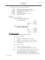
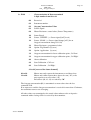
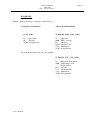
Instruction Manual
Analyser AMS 3220
for AMS ZrO2 - Probes
AMS Analysen-, Mess- und Systemtechnik GmbH
Industriestrasse 9
D-69234 Dielheim
Tel. +49-6222-78877-0
Fax. +49-6222-78877-20
e-mail: [email protected]
web-site: www.ams-dielheim.com
Instruction Manual
AMS 3220
ZrO2 - Oxygen Analyser
Page 2
Table of Contents
1
1
2
3
4
5
ELECTRONIC CONTROLLER AMS 3220
........................... 3
ZRO2-PROBES FOR THE MEASUREMENT OF OXYGEN IN FLUE GASES ........ 4
TECHNICAL DATA ELECTRONIC CONTROLLER AMS 3220 ........................... 5
DIMENSIONAL DRAWING AND FRONT VIEW OF THE ELECTRONIC
CONTROLLER AMS 3220
........................... 7
ELECTRIC CONNECTION FOR ELECTRONIC CONTROLLER AMS 3220 ........ 8
5.1
5.2
5.3
6
7
TERMINAL ASSIGNMENTS ............................................................................................................................8
INTERNAL WIRING OF ELECTRONIC CONTROLLER AMS 3220 AND ZRO2-PROBE........................................9
CABLE LENGTHS AND CABLE CROSS-SECTIONS ........................................................................................12
PREPARATIONS FOR START-UP
MEASURING MODE AND PARAMETER MODE
......................... 14
......................... 15
7.1
MEASURING MODE AMS 3220..................................................................................................................15
7.1.1
Assignment of the Operation Parameter AMS 3220.........................................................................15
7.1.2
Alignment Sensor Signal, Heater Power and Value Alarms.............................................................16
7.2
PARAMETER MODE AMS 3220 .................................................................................................................16
7.2.1
The “hidden“ button........................................................................................................................16
8
ALIGNMENT OPERATING PARAMETER ANALYSING SYSTEM ...................... 17
8.1
ALIGNMENT MEASURING RANGES ANALYSING SYSTEM ...........................................................................17
8.2
SIGNAL OUTPUT ........................................................................................................................................18
8.3
ALARMS ....................................................................................................................................................18
8.3.1
Signal Status Analyser System ..........................................................................................................18
8.3.2
Value Alarms ....................................................................................................................................18
8.4
RELAYS ALIGNMENT / CLEAR ALARMS .....................................................................................................19
9
CALIBRATION
......................... 21
9.1
SELECTING CALIBRATION GASES...............................................................................................................21
9.1.1
Measuring Oxygen Concentration in Process Gas Samples ............................................................21
9.1.2
Measuring Oxygen Concentration for Controlling and Alarming....................................................21
9.2
CALIBRATION PROCEDURE ........................................................................................................................21
9.2.1
Assigning Set-Points and Calibration Points ...................................................................................22
9.2.2
Start the Calibration.........................................................................................................................23
9.2.3
Calibrating LO and HI .....................................................................................................................23
9.2.4
Connect the Process Line, Purging and Measuring .........................................................................24
9.3
AUTOCALIBRATION ( OPTIONAL ) ...............................................................................................................25
9.3.1
Assigning the Autocalibration ..........................................................................................................25
9.3.2
Execute Autocalibration ....................................................................................................................26
9.3.3
Adjusting the Purge Time ..................................................................................................................27
9.4
CALIBRATION ERRORS...............................................................................................................................28
10 OPTIONS
10.1
10.2
11 ERROR MESSAGES
12 SERVICE
12.1
12.2
12.3
......................... 29
SERIAL INTERFACE RS232 ........................................................................................................................29
MAGNETIC SOLENOID CONTROL................................................................................................................37
......................... 38
......................... 39
CALIBRATION ............................................................................................................................................39
EXCHANGE OF THE SENSOR, LIFETIME ......................................................................................................39
PROBE MAINTENANCE...............................................................................................................................39
13 MESSAGES
14 APPENDIX
Version 07/2010
......................... 40
......................... 42
Instruction Manual
AMS 3220
ZrO2 - Oxygen Analyser
1
Page 3
Electronic Controller AMS 3220
The electronic controller AMS 3220 is the supply control and evaluation unit for all AMS
ZrO2-probes. It is TÜV-approved for large boilers in power plants, for industrial boilers
and furnaces, for waste incinerators and for crematoria.
The unit can be delivered in several housing models, available also for CENELEC zone 1
operating.
The measuring range for flue gas applications covers 0,1 - 25 vol-% oxygen permitting the
operator to adjust to the process values.
Considering process applications, measuring ranges from 0,1 vol-% to 100 vol-% O2 can
be applied. The calibration limits will be laid down in the E-PROM of the controller correspondingly.
Programming and controlling the entire measuring system will be executed with only three
push buttons: one for the operation mode, two for the cursor. A display featuring two LCD
rows indicates the measuring value and user fed data as well as the operation directions in
plain text messages. The programming level is accessible only for authorised personal
through a specific service mode.
The self diagnostics of the controller with the corresponding fault signals reduce the usually time consuming monitoring to a reasonable extent.
All instrument parameters can be comfortably set at the control unit: the calibration and
alarm data, the assignment of the display lines, as well as the two analogue outputs 0/4 –
20 mA to the current measurement limits.
Particularly important regarding the reliability of the O2 measurement is of course the identification and hence the error message while calibrating:
• The stability of the measuring signal during calibration and the plausibility of the
calculated correction data are subject to the continuous check from the electronic
controller.
Some additional functions have been integrated into the recently redesigned controller
AMS 3220:
•
•
•
•
•
•
•
•
TÜV-approval for large boilers in power plants, for industrial boilers and furnaces,
for waste incinerators and for crematoria (certification-no.936/807023/A dated 0814-2000).
In connection with the appropriate pneumatic units for automatic calibration, it offers the AUTOCAL routine for all AMS ZrO2 probes.
For the EEx-d-probe AMS 3110/150, an EEx-d-housing for the electronic unit can
be offered. Depending upon the application, either an EEx-IIC- or an EEx-d-IIBhousing is available for operating in CENELEC zone 1 and 2.
The housing of the electronic unit is made out of painted steel sheet; the enclosure
complies with IP65 and warrants an improved dissipation of the heat produced.
Signal from the sensor and heating power are galvanically isolated to keep away
wandering signals.
Two galvanically separated signal outputs 0/4 ... 20 mA are standard.
Digital interface RS232. CAN-bus interface is optionally available.
An improved A/D-converter provides better resolution and the continuous measurement from 25 vol-% down to less than 0,1 vol-% Oxygen.
Version 07/2010
Instruction Manual
AMS 3220
ZrO2 - Oxygen Analyser
2
Page 4
ZrO2-Probes for the Measurement of Oxygen in Flue Gases
The wide range of applications of ZrO2-probes for the measurement of oxygen requires the
adaptation of this measuring system to varying process conditions like temperature, aggressive flue gas and even hazardous areas. A short response time and durability of the sensor
are further major customer demands. In addition, however, ease of use, reliability, and
minimum maintenance of the analysis system are important design features.
Twenty years of experience in system technology enable AMS Analysen-, Mess- und Systemtechnik to provide ZrO2-probes with these features already built in while offering the
instruments at an attractive price.
The oxygen measuring units are used for the determination of the oxygen concentration in
flue gases of incinerators or in pure industrial gases covering the temperature range from
20°C to 1750°C.
Since the Zirconia measuring cell is located in the flue gas flow, the measurement takes
place directly (in-situ) allowing the sample extraction and conditioning system to be omitted.
Specific applications demand probes aligned to the particular process environment: e.g. to
hazardous areas classified as CENELEC zone 1 or 2, to residue free combustion processes
using natural gas or to flue gas ducts with small diameters.
System features
•
•
•
•
•
•
Specially AMS designed sensor for flue gas applications, operator replaceable
TÜV-approval for large boilers in power plants, industrial furnaces and for waste
incinerators and for crematoria
Gas wetted parts made of stainless steel, other materials are available
Range of probe lengths from 150 mm to 3000 mm
Gas temperatures up to 1750°C
EEx d II B + H2-probe for CENELEC zone 1
To operate the ZrO2-probes, a reference gas as well as a test gas for calibration is required. The corresponding tubing includes a pressure controller (or a diaphragm pump),
a filter, switching valves and a flow meter, all parts being mounted in a special sample
cabinet. For the gas supply, 6 mm Schott terminals have been chosen. Power and signal
connections are fitted to a row of terminals located in the sample cabinet.
Ambient air or instrument air can be used as reference gas.
Furthermore, the automatic calibration of all AMS ZrO2-probes within pre-selectable
time periods is feasible while using the electronic unit AMS 3220.
Alternatively to the separated mounting of pneumatic unit and electronic controller a
cabinet housing for both of them can be supplied.
Version 07/2010
Instruction Manual
AMS 3220
ZrO2 - Oxygen Analyser
3
Page 5
Technical Data Electronic Controller AMS 3220
Measuring range(s)
standard: 0,1 to 25 vol-% O2 for flue gas applications
Resolution of display
0,1 vol-% for measuring values ≥10,0 vol-%
0,01 vol-% for measuring values from 1,00 to 9,99 vol-%
display in ppmv for measuring values <1 vol-%
Measuring accuracy
± 0,1 vol-% O2 for standard measuring range
Repeatability of the
measuring signal
± 0,5% rel. for range 25 vol-% to 10 vol-% O2
± 0,05 vol-% O2 for range 10 vol-% to 0,2 vol-% O2
Drift/month
1 % rel. for standard measuring range, flue gas applications
Display
alphanumeric display with 2 x 20 digits
Monitoring
sensor voltage, heating cartridge (resistance), limits
Signal outputs
analogue output 1:
0/4 - 20 mA, galvanically isolated, max. load 600 Ohm,
freely programmable from 0,1 to 25 vol-% O2
analogue output 2: (*Option)
0/4 – 20 mA, galvanically isolated, max. load 600 Ohm,
not programmable, custom scaled
Galvanic isolation
signal input, signal outputs, heating power for the sensor
Alarms for measuring
signals
2 potential free relay contacts
max. 60 V / 0,5 A
freely programmable for the entire measuring range for limits
as well as for fast/hold
Status output
1 potential free relay contact, max. 60 V / 0,5 A; e.g. for sensor
voltage, heating cartridge
Digital interface
RS232
Certifications
TÜV-approval for large boilers in power plants, for industrial
boilers and furnaces, for waste incinerators and for crematoria
Electrical safety
CE 1996 as well as according to electromagnetic compatibility
standards and safety rules for electrical instruments
Housing/protection
wall mounting case made out of painted steel sheet/IP 65 19”
plug-in
desktop
EEx-II C- or EEx-dII B-housing
Dimensions
300 x 400 x 120 mm (WxHxD) for IP 65 housing
Weight
approx. 9 kg
Ambient temperature
5°C to 45°C
Voltage supply
24/115/230 V AC
Version 07/2010
50 or 60 Hz
Tab.1: Technical Data ZrO2-Probes
3211-500
3211-500L
3211-600
3211-700
EEx-approved
probe
EEx-approved
probe for high
temperatures
3211-000
500°C
500°C
1750°C
1100°C
500°C
1100°C
450°C
IP65
IP65
IP65
IP65
IP65
EEx d II B+H2 T3
IP65
EEx d II B+H2 T3
IP 44
<2s
< 10 s
<2s
< 10 s
<5s
< 20 s
<5s
< 20 s
<5s
< 20 s
<5s
< 20 s
<2s
< 10 s
any
but to be adjusted
downwards
any
but to be adjusted
downwards
depending from
sample tube
material
recommended
vertical suspended
up to 900°C: any
adjusted
downwards
>900°C:
vertical suspended
any
but to be adjusted
downwards
any
but to be adjusted
downwards
any
but to be adjusted
downwards
weight
(at length ...)
6,5 kg
(1000 mm)
3 kg
(500 mm)
6,5 kg
(1000 mm)
7 kg
(1000 mm)
10 kg
(500 mm)
15 kg
(1000 mm)
0,3 kg
dust content
beyond 5 g/m3
a shield made of
stainless steel is
supplied to protect
the sinter filter
beyond 5 g/m3
a shield made of
stainless steel is
supplied to protect
the sinter filter
beyond 20 g/m3
a protection shield
made of stainless
steel is
recommended
up to 20 g/m3
wet dust not
allowed!
beyond 5 g/m3
a shield made of
stainless steel is
supplied to protect
the sinter filter
beyond 20 g/m3
a protection shield
made of stainless
steel is
recommended
beyond 5 g/m3
a shield made of
stainless steel is
supplied to protect
the sinter filter
sample flow
beyond 20 m/s
a shield made of
stainless steel is
supplied to protect
the sinter filter
beyond 20 m/s
a shield made of
stainless steel is
supplied to protect
the sinter filter
no limitations
higher as 5 m/s
beyond 20 m/s
a shield made of
stainless steel is
supplied to protect
the sinter filter
no limitations
beyond 20 m/s
a shield made of
stainless steel is
supplied to protect
the sinter filter
10 minutes
10 minutes
10 minutes
10 minutes
10 minutes
10 minutes
10 minutes
ZrO2-probe
gas temperature
maximum
protection
time constant
t90-time
position
probe heating
time
Page 7
Instruction Manual
AMS 3220
ZrO2 – Oxygen Analyser
4
Dimensional Drawing and Front View of the Electronic Controller AMS 3220
Display
F
↑
↓
Hidden
Key
Version 07/2010
Instruction Manual
AMS 3220
ZrO2 – Oxygen Analyser
5
Page 8
Electric Connection for Electronic Controller AMS 3220
Terminal Assignments
5.1
This Chapter only refers to the wall mounted housing for the AMS 3220 (IP65)! Please check
the appendix for different housing models.
Fig.2: Terminal assignments wall mounted housing (IP65)
Terminal
Assignment
Connecting Terminals for the ZrO2-Probe
1
2
3
4
5
6
Heater voltage
check current voltage
check current voltage
Heater voltage
Sensor signal (+)
Sensor signal (-)
(+)
(+)
(-)
(-)
Connecting Terminals for Alarm Relays/Outputs
7
8
9
10
11
12
13
14
15
[C]
[NC]
[NO]
[C]
[NC]
[NO]
[C]
[NC]
[NO]
16
17
18
Connecting Terminals for Digital Interface RS 232 (OPTION)
[RX]
RS 232 –interface, no handshake wiring
[TX]
(see also paragraph 6)
[GND]
Version 07/2010
Alarm 1
SPDT- relay contacts, potential free
max. load 60V / 0.5A, resistive load
Alarm 2
SPDT- relay contacts, potential free
max. load 60V / 0.5A, resistive load
Status signal ( ready: yes / no )
SPDT- relay contacts, potential free
max. . load 60V / 0.5A
Page 9
Instruction Manual
AMS 3220
ZrO2 – Oxygen Analyser
Connecting Terminals for Analogue Outputs
19
20
21
22
Current Output 1
Current Output 1
Current Output 2
Current Output 2
L, N, PE
5.2
(+)
(-)
(+)
(-)
0/4 … 20mA, max. 700Ω
galvanically isolated
0/4 to 20 mA, max.700Ω
galvanically isolated
Option
Connecting Terminals for Power Supply
Power supply
230VAC/<1A, 115 VAC/<1A resp. 24VAC/<2,5A
(see your order)
Internal Wiring of Electronic Controller AMS 3220 and ZrO2-Probe
Attention:
The terminal numbers listed below refer to the wall mounted housing and to the
ZrO2- probe as ordered. For different terminal assignments please check the appendix!
The electronic controller must be connected to the proper measuring probe (see your order form)
as follows:
1) ZrO2-Probe 3211-000
AMS 3220
terminal 1
terminal 2
terminal 3
terminal 4
terminal 5
terminal 6
Version 07/2010
probe with ready-made cable pins
sensor heating
[colour: white]
sensor heater
sensor (+)
sensor (-)
[colour: white]
[colour: black]
[colour: grey]
Page 10
Instruction Manual
AMS 3220
ZrO2 – Oxygen Analyser
2) ZrO2-Probes 3211-500; -600; -700
AMS 3220
terminal 1
terminal 2
terminal 3
terminal 4
terminal 5
terminal 6
Version 07/2010
probe with Harting plug-in
sensor heating
(+)
check current voltage (+)
check current voltage (-)
sensor heating
(-)
sensor
(+)
sensor
(-)
[terminal 6]
[terminal 5]
[terminal 4]
[terminal 3]
[terminal 1]
[terminal 2]
Page 11
Instruction Manual
AMS 3220
ZrO2 – Oxygen Analyser
3) ZrO2-Probe 3210-860/150 EEx d IIB + H2 T3 and High-Temperature Probe with
EEx-d Certification
In classified areas, the electrical connection between the electronic controller and the ZrO2probe must be routed from an extra EEx e-approved terminal box (not included in the standard
delivery, but it can be ordered from AMS)! It is important to provide the EEx e-approved box
in the immediate vicinity of the measuring probe (permissible distance: max. 2 m).
AMS 3220
terminal 1
terminal 2
terminal 3
terminal 4
terminal 5
terminal 6
EEx e terminal box
probe with terminal
terminal 6
heating (+) [terminal 4]
terminal 5; bridged over to terminal 6
terminal 4; bridged over to terminal 3
terminal 3
heating(-)
[terminal 3]
terminal 2
signal (+) [terminal 1]
terminal 1
signal (-) [terminal 2]
Electronic controller
AMS 3220
EEx –
terminal
box
EEx-approved probe
3210-860/150
Fig.3: Electrical connection between electronic controller AMS 3220 and
ZrO2-probe 3210-860/150
Version 07/2010
Instruction Manual
AMS 3220
ZrO2 – Oxygen Analyser
Page 12
Cable Lengths and Cable Cross-Sections
5.3
To connect the electronic controller to the measuring probe shielded conductors have to be
used. The maximum load for the conductors is 48V/3A.
For cable lengths up to 150 m a joint cable with multiple conductors can be used for signal and
heating. Above 150 m cable length usually the conductors for signal and heating should be
routed separately.
1) Cable cross-sections for length up to 150 m
cable length "l"
minimum cross-section
=================================================================
up to 40 m
6 x 0.75 mm2
from 40 to 60m
6 x 1.0 mm2
from 60 to 90m
6 x 1.5 mm2
from 90 to 150m
6 x 2.5 mm2
2) Cable cross-sections for cables longer than 150 metres
Basically a six core cable has to be used with the core assignment as follows:
•
2 cores for the sensor signal
•
2 cores for the temperature signal (check current voltage)
•
2 cores for the heater voltage
The dimensions of the cross-sections for the signal and heater conductors required should be as
follows:
• The sensor signal conductors (terminal no. "5" and "6" of the electronic controller AMS
3220) must show a cross-section of at least 0,5mm2, regardless of the cable length. Larger cross-sections do not affect the measurement.
• The temperature signal conductors (terminal no. "2" and "3" of the electronic controller
AMS 3220) must show a cross-section of at least 0,5mm2, regardless of the cable
length.
Larger cross-sections do not affect the measurement.
•
The cross-section of the heater conductor (terminal no. "1" and "4" of the electronic
controller AMS 3220) has to be calculated as described below. In any case, it is important to observe that the overall resistance of the heating loop (excluding the sensor) does
not exceed 3,2 Ohm!
Version 07/2010
Instruction Manual
AMS 3220
ZrO2 – Oxygen Analyser
How to calculate the cross-section for the heater cores (example only):
Assume a cable with 4mm2 cross-section and 4,7 Ohm / km / core resistance.
Which cable length fits to this?
•
4,7 Ohm / km / core results in 9,4 Ohm / km / connection
(The connection comprises two cores)
•
Prescription AMS: max. permissible resistance: 3,2 Ohm
maximum cable length
3,2Ohm
= 0,340 km = 340 m
9,4Ohm / km
The cable cross-section required may be split to different cores.
Version 07/2010
Page 13
Instruction Manual
AMS 3220
ZrO2 – Oxygen Analyser
6
Page 14
Preparations for Start-Up of Electronic Controller AMS 3220
The electronic controller AMS 3220 must be connected to the ZrO2-probe as described in
Chapter 5 of this manual.
All gas lines must be connected corresponding to their assignment, in doing so we recommend
leak proofed fittings.
The reference air flow to the probe must be adjusted to 20 ... 40 Nl/h
Only for the initial start-up, the RS232-interface cable/control cable for magnetic solenoids must
be de-connected from the corresponding terminals, if the cable has been wired before.
I.
Switch on the analyser
Immediately, the display indicates the system’s identification number, and after some
seconds’ time the following message appears:
PREHEAT
WAIT...
### s
( waiting time : 600 sec. )
If this warm-up period is finished the electronic controller automatically switches to the
measuring mode. The first row of the display shows the current Oxygen concentration
value. Pre-assigned by the factory the second row does not appear but is freely programmable by the operator (see Chapter 7.1.2 of this manual).
II.
Function test
The probe must be purged through the calibration gas line with air and bottled gas while
monitoring the measuring value. The corresponding gas flow should be 30 to 60 Nl/h.
This function test is pre aligned from the supplier; this means that solid and largely correct measuring values can be expected.
III.
Regarding the terminal assignment (see diagram in Chapter 5 of this manual) all alarms
required must be connected to the proper terminal as well as the analogue output if
needed.
IV.
Option – Connect the serial interface RS232 in accordance to the terminal diagram (see
Chapter 5 of this manual).
Option – Connect the magnetic solenoid control according to the terminal diagram (see
the corresponding diagram in the appendix of this manual).
V.
VI
If required: set the customer prescribed parameters according to Chapter 7 of this manual.
Version 07/2010
Page 15
Instruction Manual
AMS 3220
ZrO2 – Oxygen Analyser
7
Measuring Mode and Parameter Mode of the Electronic Controller AMS 3220
Measuring Mode AMS 3220
7.1
The measuring value in vol-%-units is indicated in the upper row of the display like the readings for the operation parameters (see #7.1.1.)
Further information concerning the status of the device can be user assigned to the lower row as
described in #7.1.2.
All outputs and feedbacks are active.
7.1.1
Assignment of the Operation Parameter AMS 3220
The assignment of the operation parameters must follow this sequence:
•
•
•
Press or toggle the "F"-button to indicate the parameter required.
Through the cursor buttons the factory given alignments can be changed.
Repeat pressing the "F"-button to indicate the parameters successively, use the cursor
key to adjust the value required.
Not pressing any key on the control panel within 5 seconds puts the electronic controller
automatically into the measuring mode regarding the parameters just set through the display.
Warning: Faulty parameters will also be accepted from the electronic controller without any
confirmation of the apparent mistake.
Tab.2: Standard alignments (factory delivery)
Measurement Mode
Assignment Mode
Display Reading
Value
Display Reading
Value
CAL LOW
2,00
ALARM 1
Auto Reset
20,95
ALARM 1 HYST ## [rel.]
1%
ALARM 2
Auto Reset
##.## %
CAL HIGH ###.# %
ALARM 1
###.# %
25
ALARM 1 TYPE
HIGH
/LOW
HIGH
ALARM 2
25
###.# %
ALARM 2 TYPE
HIGH
/LOW
MODE
MODE
ALARM 2 HYST ## [rel.] 1%
R-HEATER
#.### Ω
8.200
RANGE LO #.## %
0,00
RANGE HI ##.## %
25,00
HIGH
For all Operation Modes
Display Reading
CHANGE 2nd LINE
NO
Version 07/2010
Value
Nothing
Instruction Manual
AMS 3220
ZrO2 – Oxygen Analyser
Page 16
7.1.2 Alignment Sensor Signal, Heater Power and Value Alarms
Through the lower display row it can be aligned as follows:
• Press or toggle the "F"-button to obtain this reading
CHANGE 2nd LINE
YES/NO
YES: assignment of the 2nd line can be changed
NO : assignment of the 2nd line cannot be changed
To call on YES or NO press the cursor button!
• The content of the 2nd line must be selected from the list shown below through the
cursor buttons:
Tab.3: Choice for the "2ND LINE DISPLAYS;"
No
1
Display Reading
NOTHING
2 line not visible
2
SENSOR VOLTAGE
Sensor signal [mV]
3
HEATER RESISTANCE
Current resistance of the sensor heater [Ω]
4
HEATER POWER
Current heater power [V]+[A]
5
ALARMS
Value alarms 1 and/or 2 if any active
7.2
Description/Function
nd
Parameter Mode AMS 3220
To extend the already described variety of parameter selection to operate the AMS 3220 a
“hidden“ button has been built in.
7.2.1
The “hidden“ button
To locate the “hidden“ button, please check Chapter 4 of this manual for the front view of the
electronic controller. This particular button is not directly visible on the front panel as indicated
by the dashed lines in the diagram. It is placed just 3 cm to the right and parallel to the “↓
↓“ –
cursor.
Pressing the “hidden“ button leads to the lower programming level of the control menu. Changing the alignment of the parameter through the “hidden“ button affects the entire mode of operation of the electronic controller AMS 3220 and thus may result in changing the complete
production system. Hence, only authorised personal should be permitted to operate the “hidden“
button.
Version 07/2010
Instruction Manual
AMS 3220
ZrO2 – Oxygen Analyser
Page 17
After completing the alignment press the “hidden“ button again to move to the upper level thus
protecting the analyser against unintentional or unauthorised operation.
If the “hidden“ button or any other button is not pressed within 10 minutes’ time the electronic
controller automatically returns to the main level. Continuously moving up and down does not
affect the performance of the analyser as far as no alterations have been carried out.
Before starting to operate the “hidden“ button and before changing the alignments or assignments in the electronic controller it is strongly recommended to read the instruction
manual very carefully and to act only as advised. Otherwise severe personal injury and/or
substantial damage to property can occur.
Warning: Faulty parameters will also be accepted from the electronic controller without any
confirmation of the apparent mistake.
8
8.1
Alignment Operating Parameter Analysing System
Alignment Measuring Ranges Analysing System
The electronic controller features are freely programmable 0/4÷20 mA – analogue output (analogue output 1, see #8.2 of this manual).
To assign the analogue output 0/4 … 20 mA to the measuring range required follow these instructions:
•
•
press the “hidden“ button (see Chapter 4 of this manual)
toggle the F-button until the following list appears on the display:
RANGE LO
###.# %
#### : start-of-scale value in vol-%
(output 0 / 4 mA)
The start-of-scale value is freely eligible through the cursor buttons.
•
toggle the F-button until the following list appears on the display:
RANGE HI
##.## %
#### : end-of-scale value in vol-%
(output 20 mA)
Through the cursor button the end-of-scale value is freely eligible.
After completing the assignment of the measuring range it is recommended to move to the upper
programming level by pressing the “hidden” button again. If the “hidden“ button or any other
button is not pressed within 10 minutes’ time the electronic controller automatically returns to the
main level.
Warning: Faulty parameters will also be accepted from the electronic controller without any confirmation of the apparent mistake.
Version 07/2010
Instruction Manual
AMS 3220
ZrO2 – Oxygen Analyser
Page 18
Signal Output
8.2
Analogue output 1: 0/4÷20 mA for Oxygen concentration
programmable; signal output electrically isolated;
Analogue output 2: Option: 0/4÷20 mA, scale custom assigned
not programmable; signal output galvanically isolated;
Alarms
8.3
The analysing system is equipped with two different kinds of messages:
1) signal status analyser system
2) value alarms
8.3.1 Signal Status Analyser System
The analyser system features a relay controlled status signal. For the technical data of the relay
see Chapter 3 and 5 of this manual. The status signal monitors the functions as follows:
warm-up phase
circuit break sensor heating
missing sensor heating circuit
power failure
The relay wiring is FAIL SAFE
8.3.2
Value Alarms
The value alarms 1 and 2 are freely configurable. A signal is triggered when the upper or lower
limit marks are exceeded respectively. The alarm signal is transferred via the corresponding
relay to the row of terminals on the rear panel of the electronic controller. Additionally, it is
indicated on the display provided that this has been properly assigned according to Chapter
7.1.2 of this manual.
For the technical data and wiring of the alarms and the corresponding relays compare Chapter 3
and 5.
Alignment of the value alarms
The value alarms are independent from each other as well as from the measuring range. Each
alarm may be assigned individually to a value in the range 0,2 ... 25 vol-%.
To align the alarm 1 follow the instructions listed below (alarm 2 has to be aligned correspondingly).
• Press the “F“-button until the following selection list appears:
ALARM 1
##.## %
##.##: alarm limit in vol-% O2
• Through the cursor buttons select the proper alarm value.
• Push the “F“-button until the following display appears:
Version 07/2010
Instruction Manual
AMS 3220
ZrO2 – Oxygen Analyser
Page 19
ALARM 1 TYPE
HIGH
/LOW
• Through the cursor buttons select the type of alarm: HIGH or LOW.
• Not pressing any button within 5 minutes’ time automatically puts the instrument back into
the measuring mode.
8.4
Relays Alignment / Clear Alarms
•
•
Press the “hidden“ button (how to locate this button compare Chapter 4 of this manual)
Press the F-button until the following selection list appears:
ALARM 1 MODE
*****************
***************** alarm modus indicated
• Through the cursor buttons one of the modes listed below may be chosen:
•
HOLD (MANUAL RESET)
The alarm holds itself. Measuring values above or below the alarm threshold causes
the flashing of the message AL 1 in the lower row of the display - if it was assigned
before. To clear the message press the cursor button ↑ (the message AL 2 will only
be cleared by pressing the cursor button ↓).
•
DISABLED
The alarm is switched off.
•
AUTO RESET
The alarm clears automatically. Measuring values above or below the alarm threshold are indicated as an alarm message on the lower row of the display but are then
automatically reset (message cleared) if assigned before.
To assign a particular deviation value permitted select AUTO RESET as described
above and press the F-button again. The adjacent message appears on the display:
AL 1 HYST ## %[rel.]
## difference to the alarm value in % [rel.]
The value of the deviation can be selected through the cursor button from 0,1 ... 10
% (relative to the alarm threshold).
•
Version 07/2010
DELAYED
The alarm clears itself. Measuring values above or below the alarm threshold are
indicated as an alarm message on the lower row of the display but are then reset
(message cleared) after a pre-set delay time if assigned before.
To assign a particular deviation value permitted select AUTO RESET as described
above and press the F-button again. The following message appears on the display:
Instruction Manual
AMS 3220
ZrO2 – Oxygen Analyser
AL 1 DELAY ## s
Page 20
## Delay time in [s]
The delay time can be chosen from 1 … 60 seconds.
All alarms are also available at the terminals on the rear panel of the electronic controller
via the relay wiring respectively (see Chapter 3 for the technical data of the relays and Chapter 5 for the terminal assignment).
After completing the assignment of the measuring range it is recommended to move to the upper
programming level by pressing the “hidden” button again. If the “hidden“ button or any other
button is not pressed within 10 minutes’ time the electronic controller automatically returns to the
main level.
Warning: Faulty parameters will also be accepted from the electronic controller without any
confirmation of the apparent mistake.
Version 07/2010
Instruction Manual
AMS 3220
ZrO2 – Oxygen Analyser
9
9.1
Page 21
Calibration
Selecting Calibration Gases
The Oxygen analyser must be calibrated with two different calibration gases. Depending on the
application, the calibration gases must be chosen as follows:
9.1.1 Measuring Oxygen Concentration in Process Gas Samples
To determine the Oxygen concentrations in a custom set range the calibration gases must cover
the upper and the lower set point of this Oxygen concentration range.
Example: Measuring a process gas with an Oxygen concentration of about 1 … 10 vol-% in N2
calibration gases with following oxygen concentrations are recommended:
For the lower set point: 2 Vol-% O2 in N2 , as the lower calibration point.
For the upper set point: 20,95 Vol-% O2 in N2 , as the upper calibration point.
9.1.2 Measuring Oxygen Concentration for Controlling and Alarming
Usually in these application areas the Oxygen concentration is relatively constant just varying
in a narrow concentration range around the correct value. Correspondingly, for process control
one calibration gas should show the correct Oxygen concentration value and for alarming purposes the lower or upper alarm value.
The Oxygen concentration of the second calibration gas should be aligned to the range of deviation from the correct Oxygen value, it may contain more or less Oxygen compared to process
gas.
9.2
Calibration Procedure
The calibration procedure of the analysing system AMS 3220 occurs semi-automatic as well as
in multiple steps.
A single calibration step is started manually but supervised and controlled automatically by the
analyser.
The calibration procedure may be stopped anytime through pressing the F-button. The system
functions will not be affected through this handling.
While calibrating the system step by step as listed below one should carefully consider the different meaning of upper (HI) and lower calibration point (LO).
Version 07/2010
Instruction Manual
AMS 3220
ZrO2 – Oxygen Analyser
Page 22
Calibration sequence:
I. check set-points for calibration: see Chapter 9.2.1
II. start calibration 9.2.2
III. calibrating LO and HI: see 9.2.3
IV. connect the process line, purging and measuring: see 9.2.4
Important:
During the calibration procedure all alarm messages and signal outputs are fixed. The last
measuring value is indicated on the display for verification.
9.2.1
Assigning Set-Points and Calibration Points
Before starting the calibration of the analysing system the set points of the calibration gases
used must be assigned to the instrument as described below.
• Press the F-button until the adjacent message appears:
CAL LOW
##.## %
####
Oxygen concentration in vol-% O2
for the lower calibration point
• With the help of the cursor buttons, assign the lower calibration point according to the calibration gas specification label.
• Press the F-button again until the following message appears:
CAL HIGH
##.## %
####
Oxygen concentration in vol-% O2
for the upper calibration point
• Through the cursor buttons, assign the upper calibration point according to the calibration
gas specification label.
It is important for a reasonable calibration that the proportion of the Oxygen concentrations in
the two reference gases employed should be at least
upper set - point 5
≥
lower set - point 1
The analyser system monitors this proportion and set-points with a lower proportion as shown
cannot be assigned to the analysing system.
Version 07/2010
Instruction Manual
AMS 3220
ZrO2 – Oxygen Analyser
9.2.2
Page 23
Start the Calibration
Important I
During the measuring phase no button should be pressed! Pressing the F-button after
purge time breaks off the calibration procedure.
Important II
While calibrating, the Oxygen concentration should not be altered or only slightly at the most.
Important III
Regarding the calibrating sequence it is recommended to calibrate the lower calibration point
first and then the upper calibration point.
LO:
Start the calibration of the lower calibrating point
Press and hold cursor button "↓", push F-button. Release the buttons. The adjacent
message appears on the display.
PUT LO-GAS
[##.## %]
PRESS F IF STABLE
HI:
Index:
##.##
measured Oxygen concentration
Start the calibration of the upper calibration point
Press and hold cursor button "↑", push F-button. Release the buttons. The adjacent
message appears on the display.
PUT HI-GAS
[##.## %]
PRESS F IF STABLE
Index:
##.##
measured Oxygen concentration
Proceed as described in #9.2.3
9.2.3
Calibrating LO and HI
Connect the analyser system to the calibration gas line for the lower or upper calibration
point respectively. Adjust the gas flow to 40 … 60 Nl/h. Monitor the current Oxygen
concentration as indicated in brackets on the display. Wait until measured Oxygen concentration is stable.
Version 07/2010
Instruction Manual
AMS 3220
ZrO2 – Oxygen Analyser
Page 24
Press F-button and the following messages appear successively:
CAL xx.xx % [##.## %]
PURGING… ttt s
Index
xx.xx pre-aligned calibration gas concentration
##.## measured calibration gas concentration
ttt s
counter for purging time left
CAL xx.xx % [##.## %]
SAMPLING… ttt s
Index
xx.xx pre-aligned calibration gas concentra##.## measured calibration gas concentration
ttt s
counter for sampling time left
tion
Once this measuring sequence is finished the analyser automatically calculates and stores the
calibration curve. The following message appears on the display:
PUT PR-GAS
[##.## %]
PRESS F IF STABLE
9.2.4
Connect the Process Line, Purging and Measuring
Connect the analyser system to the process line.
Press the F-button, the adjacent message appears on the display:
PROC GAS
[##.## %]
PURGING… ttt s
Index: ##.## measured Oxygen concentration
ttt
time left over
The measuring procedure for the process gas either starts automatically after the purging time is
finished or after pressing the F-button.
Important IV
Terminating the purging phase before the purging time has run out may cause unreliable measuring values for a short period of time since the measuring cell must align to the current Oxygen concentration.
Version 07/2010
Instruction Manual
AMS 3220
ZrO2 – Oxygen Analyser
9.3
Page 25
Autocalibration ( optional )
The autocalibration mode calibrates the analyser system automatically within pre-selectable
time periods.
The autocalibration procedure is accessible only if the corresponding magnetic solenoid valves
and the control system are supplied. To connect the electronic controller to the magnetic solenoid valves through a particular cable see the appendix of this manual.
Note
If the measuring value indicated changes while connecting the control cable for the magnetic
solenoid valves, a ground loop may be the cause. To correct this fault detach the cable shield at
one end of the control cable.
9.3.1 Assigning the Autocalibration
The autocalibration mode of the electronic controller is deactivated when delivered.
To align the autocalibration just follow the instructions as listed below.
• Press or toggle the F-button until the following message appears on the display:
AUTO CAL TYPE
*********
********* selection list
• press the cursor buttons to select the calibration sequence as listed below:
- HIGH-LOW =
Start "CAL-HIGH“ calibration first, then go on with "CAL-LOW“
- LOW-HIGH =
Start "CAL-LOW“ calibration first, then go on with "CAL-HIGH“
This sequence is recommended by the supplier.
- HIGH
=
Only "CAL-HIGH" calibration will be executed
- LOW
=
Only "CAL-LOW" calibration will be executed
• Press or toggle the F-button until the following message appears on the display:
AUTO CAL TIME
#### h
#### time interval required between two
NEXT CAL TIME
**** h
calibrations
**** time period to the next calibration
• Select the time interval between two calibrations through the cursor buttons. The interval
time can be freely chosen from 1 … 9999 hours with one hour steps.
The lower row indicates the time left to the next calibration.
Note
Setting a time interval starts the calibration procedure at the time prescribed automatically.
Version 07/2010
Instruction Manual
AMS 3220
ZrO2 – Oxygen Analyser
Page 26
Note
Setting AUTO CAL TIME = 0 and subsequently setting a time interval starts the calibration
procedure immediately.
Note
Setting "AUTO. CAL. TIME“……0
Clears the autocalibration mode
9.3.2 Execute Autocalibration
Note
Before executing autocalibration the assignment procedure (see Chapter 9.4.1) should be completed.
The autocalibration procedure takes into account the pre-assigned calibration sequence (compare Chapter 9.4.1). Therefore, by choosing the "LOW-HIGH"- or "HIGH-LOW"-mode the
autocalibration procedure is performed automatically for both calibrations points.
The autocalibration mode starts
either
• automatically through selecting "AUTO CAL.TIME" and setting a time interval
or
• manually through pressing the two cursor buttons simultaneously.
The following messages appear successively on the display:
CAL xx.xx PPM [##.## PPM]
Index: xx.xx pre-assigned calibration value
PURGING... ttt
##.## current measuring value
ttt
purging time left in seconds
CAL xx.xx PPM [##.## PPM]
SAMPLING... ttt
Index: xx.xx pre-assigned calibration value
##.## current measuring value
ttt
sampling time left in seconds
The value in the upper row of the display indicates the calibration mode and the pre-assigned
concentration value. The latter must correspond with the measuring value of the calibration gas
currently used after the purging time has run out. Otherwise, the autocalibration procedure has
to be stopped and the calibration procedure following Chapter 9.2 must be repeated.
After this, start the autocalibration mode manually through pressing again the two cursor buttons simultaneously.
Note
After finishing the "PURGING"-phase the indicated measuring value should be constant.
The electronic controller controls the autocalibration procedure internally, possible faults are
indicated on the display.
Version 07/2010
Instruction Manual
AMS 3220
ZrO2 – Oxygen Analyser
Page 27
When the Autocalibration is terminated successfully the adjacent message appears on the
display:
PROC GAS [##.## PPM]
##.## current measuring value
PURGING... ttt
ttt
purging time left in seconds
This menu indicates that the ZrO2-probe is now purged with process gas. When the purging
phase is finished the electronic controller automatically starts measuring.
9.3.3 Adjusting the Purge Time
Note 1
Each calibration sequence starts and ends with purging the analyser
for a specific time period primarily factory adjusted.
Note 2
Proper purging is required for reliable as well as solid measuring values. If the measuring values during the calibration sequence SAMPLING are not stable, an error message appears on the display and
the purge time should be extended:
CALIBRATION INSTABLE
Note 3
Aligning the purge time may be required to take into account the volume of the supply gas lines.
Purge time setting
• Press the Hidden-key, the adjacent message appears on the display;
• press the “F“-key until this message appears:
PURGE TIME
### s
• via the two arrow keys " ↑ " and " ↓ ", the purge time can
be changed;
(The Purge Time may be assigned individually to a value in the
range 30 ... 900 (1200) sec)
• Not pressing any button within 5 minutes’ time automatically puts
the instrument back into the measuring mode.
Version 07/2010
Instruction Manual
AMS 3220
ZrO2 – Oxygen Analyser
9.4
Page 28
Calibration Errors
The calibration procedure will be controlled continuously and calibration errors will be indicated on the display.
Note
Calibration errors cause the calibration procedure to stop. To launch the measuring mode again,
just press the F-button.
The interruption of a calibration sequence does not affect the performance of the analysing system.
Possible calibration errors indicated on the display:
A.
CALIBRATION ERROR 10
PRESS F TO CONTINUE
Cause:
This message may be caused by inconsistent measuring values due to inadmissible
variations of the measuring signal.
Possible sources::
• Gas flow in the calibration gas line is too low
• Leaking calibration gas line
• Pressure variations in the calibration gas line
• Gas flow in the flue gas duct is too high
• Faulty sensor
B.
CALIBRATION ERROR 11
PRESS F TO CONTINUE
Cause:
This message may be caused from implausible calibration results.
Possible errors:
• No gas flow in the calibration gas line
• Incorrect calibration parameters
Version 07/2010
Instruction Manual
AMS 3220
ZrO2 – Oxygen Analyser
Page 29
10 Options
10.1 Serial Interface RS232
The electronic controller can be optionally equipped with a serial interface RS232 to transfer the
data to a remote computer through a specific evaluation programme or just a simple terminal
programme.
Note
If the measuring value indicated changes while connecting the control cable for the magnetic
solenoid valves, a ground loop may be the cause. To correct this fault detach the cable shield at
one end of the control cable.
In order to connect the electronic controller and the remote computer via a serial interface
RS232 follow these instructions:
1. The connecting line must be a non-modem-cable with the pin assignment as shown in
drawing number 03-3220-000-36-A4 (see appendix).
2. Start the terminal programme on the remote computer and take care of the assignments
as follows:
COM-Port:
Baud-Rate:
Start-Bits:
Data Bits:
Stop Bits:
Parity:
(COM-interface at the computer)
19200 bps
1
8
1
None
Data Protocol :
Whenever the master sends a data telegram to the instrument, the instrument is required either to
- send data
- change parameters or
- carry out a procedure
The instrument answers by sending the data required resp. by changing the parameters or by carrying out a procedure (e.g. calibration).
Each telegram is for one kind of information only. The instrument answers with a
maximum delay of 0.2 seconds.
Each telegram consists of several ‚fields’, which are separated by a maximum of
5 ‚spacings’.
Each telegram is closed by <CR> (Carriage Return) .
The instrument recognises and evaluates a telegram only after receiving <CR> .
Description of ‘Fields’ and their meaning and formats
Version 07/2010
Page 30
Instruction Manual
AMS 3220
ZrO2 – Oxygen Analyser
Each telegram consists of a maximum of 6 ‚Fields’ :
1st Field:
2nd Field:
3rd Field:
4th Field:
5th Field:
6th Field:
Definition of the meaning of the telegram
Status Field in messages from the instrument only
characterises the data transmitted
Field for data sent
optional field for supplementary data
Telegram End <CR>
Example
(for interpretation see further below) :
Telegram from Master to Instrument
S_11_-12.3456_<CR>
S
11
-12.3456
<CR>
= 1st
= 3rd
= 4th
= 6th
Field
Field
Field
Field
Telegram from Instrument to Master
L_0000_11_-12.3456_<CR>
L
0000
11
-12.3456
<CR>
Description of the ‚Fields’
= 1st Field
= 2nd Field
= 3rd Field
= 4th Field
= 6th Field
1st Field: Definition of the meaning of the telegram
From Master to Instrument :
G
(Get) Master requests Instrument to send data
S
(Set) Master requests Instrument to change a parameter
M
(Make) Master requests Instrument to start a procedure
(e.g. calibration)
From Instrument to Master
Version 07/2010
T
Answer to G : Instrument sends data;
L
Answer to S , Instrument confirms changed parameter
E
Answer to M , Instrument confirms execution of procedure
X
this code indicates, that the self-checking procedures in the
instrument have detected an error or a malfunction;
such errors or malfunctions are stored in ‘flags’ and sent in
Field 2 of the answer telegram from the instrument to the master.
Page 31
Instruction Manual
AMS 3220
ZrO2 – Oxygen Analyser
2nd Field
:
Status Field: 16 Bit Error Flags,
for messages from the instrument to the master only !!
Coding is bit by bit : 0 = OK
B0:
1 = Error
Communication Error (RS232 frame error, timeout…)
B1:
B2:
B3:
Unknown Command
B4:
Parameter-Error (Parameter outside allowed range)
B5:
Command could not be executed
B6:
B7:
B8:
After power on :
Sensor has not yet reached the operating temperature
B9:
Instrument is busy with a calibration procedure
B10:
B11:
B12: Sensor-Temperature Error
B13:
B14: Heater (or heater line) broken
B15: Heater shortcut
Format for transmission :
HEX
Examples :
HEX
(Binary)
No Error :
0000 ( 00000000 00000000 )
Heating up phase:
0100 ( 00000001 00000000 )
Temp. Error, heater broken:
5000 ( 01010000 00000000 )
Version 07/2010
Instruction Manual
AMS 3220
ZrO2 – Oxygen Analyser
3rd Field
Page 32
:
Characterisation of Data transmitted
2-digit number from 00 to 99
00:
Reservied
01:
Instrument number
02:
Oxygen Concentration Value
03:
Sensor-Signal
04:
Heater Resistance; actual value (Sensor-Temperature)
10:
Status Signal
11:
Sensor „OFFSET“ ( = Sensor signal [mV] in air)
12:
Sensor „SPAN“ ( = Sensor signal change [mV] for an
Oxygen concentration change of 1:10)
13:
Heater Resistance; programmed value
21:
Option: Tag-Number (by user)
22:
Option: Application (by user)
31:
Oxygen concentration for lower calibration point „Cal Low“
32:
Oxygen concentration for upper calibration point „Cal High“
80:
Abort calibration
81:
Start Calibration „Cal Low“
82:
Start Calibration „Cal High“
91 to 99 [reserved for future demand]
01 to 10
11 to 90
Master may only request the instrument to send those data
Master may either request those data to be sent (“G”) or he
may request to set new values (“S”)
Procedures (80, 81, 82) are started by “M”
The Oxygen concentration (02) is transmitted as mean value since the last
command G 02
If no request to send the Oxygen concentration is received for more than 15 minutes,
the transmitter starts a new averaging.
All other values are transmitted as the actual values whenever the re4spective
command with a closing <CR> is received by the transmitter.
Version 07/2010
Instruction Manual
AMS 3220
ZrO2 – Oxygen Analyser
4th Field:
Page 33
Data
In this field, the data as characterised in field 3 are listed.
The length and the format of the field is determined by the type
of the data. The maximum length is 50 Bytes.
Format:
02
03
04
12
11
12
13
Oxygen (floating point) [Vol% o. ppm]
Sensor-Signal
floating point [mV]
Heater resistance
floating point [Ohm]
(actual value)
Status
0
OPERATING
1
START UP
2
PREHEATING
3
SETUP-MODE
4
CALIBRATION
5
6
SYSTEM ALARM
floating point
floating point [dimensionslos]
floating point [Ohm]
21
22
OFFSET
SPAN
Heater resistance
(programmed value)
TAG-Number
Application
31
32
Cal Gas Low
Cal Gas High
floating point [Vol%]
floating point [Vol%]
string
string
5th Field:
Supplementary Data
This field contains supplementary data for field 4, e.g. the dimensions
or units of the measured values [Vol%, ppm, mV, Ohm,….]
Field 5 is transmitted ‚on demand’ only and may be omitted.
Maximum length is 20 Bytes.
6 th Field:
Telegram End <CR>
Version 07/2010
Page 34
Instruction Manual
AMS 3220
ZrO2 – Oxygen Analyser
EXAMPLES :
Remark : In the following, a ‘spacing’ is indicated by “_”
.
1 Request from Master
Answer from Instrument
G_02_<CR>
T_0000_02_20.95_%O2_<CR>
G
Send Data
02
Oxygen
<CR> Telegram end
T
0000
02
20.95
%O2
<CR>
Data sent
HEX : no error
Oxygen
Oxygen Value
Dimension
Telegram end
Or, if the instrument is not o.k., par example :
X_5000_02_17.5_%O2_<CR>
X
Error from Instrument
5000 Temperature error,
heater broken
02
Oxygen
17. 5 Sauerstoffwert
%O2 Dimension
<CR> Telegram end
Version 07/2010
Page 35
Instruction Manual
AMS 3220
ZrO2 – Oxygen Analyser
.
2 Command from Master
Answer form Instrument
Status: o.k.
S_11_-12.34_<CR>
L_0000_11_-12.34_<CR>
S
11
-12.34
<CR>
_
L
0000
11
-12.34
<CR>
_
Set Parameter
OFFSET
new Value for Offset
Telegram end
Spacing
Parameter changed
no error
OFFSET
new value for Offset
Telegram end
Spacing
Status : not o.k.;
could not change parameter
X_0001_11_>CR>
X
0001
11
<CR>
_
.
3 Command from Master
Malfunction
Transmission error
OFFSET
Telegram end
Spacing
Answer form Instrument
Status: o.k.
M_81_<CR>
E_0000_81_11.5_ppm_<CR>
M
Command ‚Make’
81
Calibration „Cal Low“
<CR>
Telegram end
_
Spacing
E
0000
81
11.5
ppm
<CR>
_
Executed
no error
Calibration „Cal Low“
Value for Cal Low Gas
dimension
Telegram end
Spacing
The calibration needs approx. 100 Seconds and may be aborted by M_80_<CR>
at any time.
Version 07/2010
Page 36
Instruction Manual
AMS 3220
ZrO2 – Oxygen Analyser
10.2 Magnetic Solenoid Control
The magnetic solenoid control board for the analysing system AMS 3220 is placed in a specific
aluminium made box (dimensions 120x220x80 mm).
To connect electronic controller and solenoid control board a 1:1 connection line has to be supplied as described in the appendix.
Voltage supply: 115VAC or 230VAC (check your order form).
terminalblock 1
plug- terminalin
block 2
terminalblock 3
terminalblock 4
terminalblock 5
Fig. 4: Power board for magnetic solenoid control
The terminals on the power board are to assign as follows:
(see AMS Drawing No.: 00-3220-000-43-A3 at the appendix)
Terminal block
1
2
3
4+5
Connection
voltage supply 115VAC or 230VAC (power 20 VA)
magnetic solenoid valve switching over measuring/calibrating [MV1]
magnetic solenoid valve switching over calibration gas "HIGH" (air)/
calibration gas "LOW" [MV2]
free for optional control
Note
Connecting the terminals one should regard the proper polarity concerning the supply lines for
the magnetic solenoid valves. The latter are designed for 24 VDC if not described otherwise.
Note
Pay attention to the marks engraved on the board next to the terminals while assigning voltage
supply and magnetic solenoid valves.
11 Error Messages
Version 07/2010
Instruction Manual
AMS 3220
ZrO2 – Oxygen Analyser
Page 37
• HEATER ALARM
HEATER SHORTCUT
Cause:
Short-circuit in probe heating line terminal 1 and 4
(wall mountable housing)
error correction:
test the sensor heating lines for short-circuit
(probe heating line resistance is approximately 2Ω at room temperature and approx.
9Ω at operating temperature.)
• HEATER ALARM
HEATER MISSING
Cause:
Broken or not connected probe heating line terminal 1 and 4
(wall mountable housing)
error correction:
I.
or
II.
test terminal for connecting cables
check probe heating lines for a break
(probe heating line resistance is approximately 2Ω at room temperature and
approx. 9Ω at operating temperature.)
• FACT DEF LOADED
PRESS F TO START
Cause:
• faulty EEPROM
• faults causing a "RESET"
e.g. a short-circuit in the probe heating line during normal operation
error correction:
•
•
•
•
•
Version 07/2010
press F-button
if the error message is not cleared the EEPROM is faulty and must be exchanged
if the error message is cleared: the EPROM is ok and the factory supplied settings will be loaded again after the F-button has been pressed
alarms and calibration points must be realigned
re-calibration at the earliest after operating 1 hour
Instruction Manual
AMS 3220
ZrO2 – Oxygen Analyser
Page 38
12 Service
The electronic controller AMS 3220 features a substantial self-diagnostic philosophy with fault
signals. Maintenance is only necessary for the probe: cleaning from dust and deposits and in
case the sensor has to be exchanged.
12.1 Calibration
Basically calibration should be executed for two concentrations (see #9).
It is recommended to calibrate after at least one hour operation and at regular operation temperature. Regularly repeating the calibration within 3 months period is also recommended. This
calibration period might be extended up to 6 months due to the long-term stability of the ZrO2.
The calibration period might be shortened if the probe is exposed to aggressive chemicals,
heavy dust deposits, high temperatures and temperature differences etc. Just monitor the successive measuring values at the calibration points for some time to detect solid deviations from
the initial calibration.
12.2 Exchange of the Sensor, Lifetime
The average lifetime of the sensor is about two years. This time might be extended regarding
applications with almost constant operation temperature and less aggressive gas mixtures e.g.
for flue gas measurements in natural gas incinerators.
It is recommended to exchange the sensor after 30 months operation. Storing a sensor for up to
two years does not affect its lifetime or performance.
The regular “ageing“ of the sensor can be compensated for some time through calibrations repeated periodically.
Overused sensors exhibit faulty calibration values indicating the need for replacement.
12.3Probe Maintenance
Service for the probe is restricted to cleaning from deposits or pollution. These effects are signalled through delayed response time and extended time needed for stable measuring values.
Version 07/2010
Instruction Manual
AMS 3220
ZrO2 – Oxygen Analyser
Page 39
13 Messages
Basics
R-HEATER
#.### Ω ..........................................................................................................................................15
RANGE LO #.## %...........................................................................................................................................15/17
RANGE HI ##.## %..........................................................................................................................................15/17
Alarms
ALARM 1 ###.# % .........................................................................................................................................15/19
ALARM 1 TYPE...............................................................................................................................................15/19
HIGH
/LOW
ALARM 1 MODE ...........................................................................................................................................15/18
HOLD (MANUAL RESET)..................................................................................................................................19
DISABELD ...........................................................................................................................................................19
AUTO RESET.......................................................................................................................................................19
DELAYED ............................................................................................................................................................19
ALARM 1 HYST ## [rel.] ..................................................................................................................................15/19
AL 1 DELAY ## s...................................................................................................................................................20
ALARM 2 ###.# % .........................................................................................................................................15/19
ALARM 2 TYPE...............................................................................................................................................15/19
HIGH
/LOW
ALARM 2 MODE ...........................................................................................................................................15/19
HOLD (MANUAL RESET)..................................................................................................................................19
DISABELD ...........................................................................................................................................................19
AUTO RESET.......................................................................................................................................................19
DELAYED ............................................................................................................................................................19
ALARM 2 HYST ## [rel.] ..................................................................................................................................15/19
AL 2 DELAY ## s...................................................................................................................................................20
Lower row
CHANGE 2´ND LINE .......................................................................................................................................15/16
NOTHING................................................................................................................................................................16
SENSOR VOLTAGE ...............................................................................................................................................16
HEATER RESISTANCE .........................................................................................................................................16
HEATER POWER ...................................................................................................................................................16
ALARMS .................................................................................................................................................................16
Calibration
CAL LOW
##.## %.........................................................................................................................................15/22
CAL HIGH ###.# %.........................................................................................................................................15/22
PUT LO-GAS
[##.## %]...................................................................................................................................23
PRESS F TO CONTINUE
PUT HI-GAS
[##.## %] ....................................................................................................................................23
PRESS F TO CONTINUE
CAL xx.xx % [##.## %] ..................................................................................................................................24/26
PURGING… ttt s
CAL xx.xx % [##.## %] ..................................................................................................................................24/26
SAMPLING… ttt s
Version 07/2010
Instruction Manual
AMS 3220
ZrO2 – Oxygen Analyser
Page 40
PUT PR-GAS
[##.## %] .................................................................................................................................24
PRESS F TO CONTINUE
PROC GAS
[##.## %].............................................................................................................................24/26
PURGING… ttt s
Autocalibration
AUTO CAL TYPE .................................................................................................................................................25
AUTO CAL TIME
NEXT CAL TIME
#### h ..............................................................................................................................25
**** h
PURGE TIME .......................................................................................................................................................258
Calibration error
CALIBRATION ERROR 10....................................................................................................................................28
PRESS F TO CONTINUE
CALIBRATION ERROR 11....................................................................................................................................28
PRESS F TO CONTINUE
System error
HEATER ALARM ...................................................................................................................................................37
HEATER SHORTCUT
HEATER ALARM ...................................................................................................................................................37
HEATER MISSING
FACT DEF LOADED ..............................................................................................................................................37
PRESS F TO START
Version 07/2010
Instruction Manual
AMS 3220
ZrO2 – Oxygen Analyser
14 Appendix
Drawings
Dimensions
Version 07/2010
Page 41