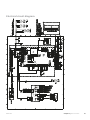
1
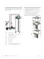
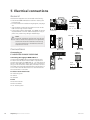
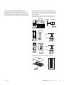
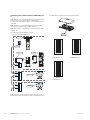
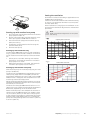
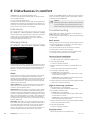
Connecting the communication to NIBE FLM no. 24
The DIP switch (AA5-S2) must be set as follows.
NIBE FLM no 2 is connected directly to the heat pump
on the input card (terminal block AA3-X4) in
F1145/F1155/F1245/F1255 or on terminal block X6
in F1345.
K
LE
NIBE FLM no. 3 is connected to the accessory card's
terminal block (AA5-X4) in NIBE FLM no. 2.
NIBE FLM no. 4 is connected in a similar way in NIBE
FLM no. 3.
Use cable type LiYY, EKKX or similar.
$$6
)))))
A
B
GND
LEK
$$;
ON
)
$$;
$$6
B
GND
AA3-X4
15
15
14
14
13
13
LEK
))
))
1,%( )/0 QR -X8
8
7
6
5
4
3
2
1
6
7
7
11
9
8
-X2
5
6
8
GND
9
4
B
3
5
-X4
4
3
1
22
ON
A
-X9
24 23 22 21 20 19 18 17 16 15 14 13 12 11 10
2
GND
AA5-X4
1
B
ON
A
2
2
1
3
4
-X10
5
6
33
-X1 N
7
8
L
PE
PE
44
55
66
$$6
88
)/0 QR NIBE FLM no. 4
1,%( )/0 QR 3
24 23 22 21 20 19 18 17 16 15 14 13 12 11 10
9
8
7
6
5
4
3
2
1
5
-X8
6
-X2
7
7
8
6
5
11
-X4
4
3
1
2
2
1
3
4
22
33
44
9
8
4
B
GND
2
A
1
GND
AA5-X4
-X9
ON
B
NIBE FLM no. 3
$$;
77
A
$$6
1 2 3 4 5 6 7 8
NIBE FLM no. 2
A
1 2 3 4 5 6 7 8
1 2 3 4
ON
X6
1 2 3 4 5 6 7 8
;
-X10
5
6
-X1 N
7
8
L
PE
PE
$$;
55
66
77
88
)/0 QR NIBE FLM 2-4 can be connected in a similar way to a
previously installed accessory and its accessory card.
16
Chapter 5 | Electrical connections
NIBE FLM