1
Leader in Electrics & Automation
GLOFA GM Series
Automation Equipment
Leader in Industrial Electric Power and
Automation creating environment-friendly and
highly productive industrial society as
Total-solution provider
LG Industrial Systems (LGIS), founded in 1974, as a leader in Korean
industrial electric power and automation market is trying to be a global
leader. LGIS will fulfill its mission providing total-solution as a
forerunner of creating environment-friendly and productive industrial
future society.
2 I
GLOFA GM Series
Programmable Logic Controller
Table of contents
GLOFA-GM7 I 9
Analog input module (GM4/6) I 44
GLOFA-GM7U I 11
Analog output module (GM4/6) I 45
GLOFA-GM7/GM7U wiring diagram I 14
Temperature control module (GM4) I 46
GLOFA-GM7/GM7U expansion unit I 16
Thermocouple module (GM4/6) I 47
Block type PLC configuration I 19
RTD module (GM4) I 47
GLOFA-GM6 I 21
PID control module (GM4) I 48
GLOFA-GM4 I 25
Analog timer module (GM4) I 48
GLOFA-GM Fast Enet (Ethernet) system I 32
Positioning module (APM): (GM4/6) I 49
GLOFA-GM Ethernet system configuration I 33
I/O interface with external equipment I 50
GLOFA-GM Fnet (Fieldbus) system I 34
Example of connection with drivers I 52
GLOFA-GM Fnet system configuration I 35
High speed counter module (GM4/6) I 53
GLOFA-GM Cnet (Computer link) system I 36
GLOFA-GM program S/W (GMWIN) I 54
GLOFA-GM Cnet (Computer link) system configuration I 37
PMU 30 series I 55
GLOFA-GM Dnet (DeviceNet) system I 38
XGT PANEL I 56
GLOFA-GM Dnet system configuration I 39
Command I 57
GLOFA-GM Pnet (Profibus-DP) system I 40
Product list I 63
GLOFA-GM Pnet system configuration I 41
Dimensions I 67
SMART I/O I 42
Cable connection I 69
SMART I/O system configuration I 43
GLOFA-GM Series
I3
GLOFA-GM Series
Network
Specification
Max. I/O points
(Using remote I/O)
Execution
speed
( /step)
GM4
GM4-CPUA 2,048 (4,096)
GM4-CPUB 2,048 (8,192)
GM4-CPUC 3,584 (32,768)
GM6
Series
Memory capacity (byte)
Program
Data
0.2
0.2
0.12
128K
128K
1M
52K
50K
428K
384
0.5
68K
32K
GM7
10~80
0.5
68K
32K
GM7U
20~120
0.1
132K
44K
Enet: Ethernet
Fnet: Fieldbus
Cnet: Computer Link
Rnet: Dedicated communication for LGIS SMART I/O
Dnet: DeviceNet
Fast
Enet
Fnet
Cnet
Dnet
Pnet
slave
slave
Rnet
Pnet: Profibus-DP
Special modules
Series
Analog
I/O
GM4
GM6
GM7 * 2)
Position
control
7 Types
G4F-AD3A (8Ch)
G4F-AD2A (4Ch)
G4F-DA3V (8Ch)
G4F-DA2V (4Ch)
G4F-DA3I (8Ch)
G4F-DA2I (4Ch)
G4F-DA1A (2Ch)
3 Types
G6F-AD2A (4Ch)
G6F-DA2V (4Ch)
G6F-DA2I (4Ch)
3 Types
G4F-HSCA
(1Ch)
G4F-HO1A
(2Ch)
G4F-HD1A
(2Ch)
3 Types
Built-in (1Ch)
Built-in
(Pulse output)
Built-in (4Ch)
Built-in
Control axis: 2
7 Types
GM7U * 2)
High speed
control
6 Types
G4F-PPXO
G4F-PPXD * 1)
(Axis X=1, 2, 3)
PID control
2 Types
G4F-PIDB
(16 loops)
G4F-TMCA
(2 loops)
Thermocouple
input
1 Type
G4F-TC2A
(4Ch)
Analog
timer
RTD
1 Type
1 Type
G4F-RD2A (4Ch) G4F-AT3A
(8 points)
* 1)
4 Types
G6F-HSCA (1Ch)
G6F-HO1A
(2Ch)
G6F-HD1A * 1)
(2Ch)
Built-in (CPUC)
6 Types
Built-in
G6F-PPXO
(CPUB/CPUC)
* 1)
G6F-PPXD
(Axis X=1, 2, 3)
Built-in
1 Type
G6F-TC2A
(4Ch)
-
-
1 Type
1 Type
G7F-AT2A
(4 points)
*1) -HO1A, -PPXO: Open collector type,
-HD1A, -PPXD: Line drive type
*2) Refer to P19
Part number name
G
Type
4
6
7
4 I
GM4
GM6
GM7
I
Q
H
L
F
Input
Output
Hybrid
Comm.
Special
A1
A2
D2
RY
SS
TR
DR
DT
I/O type
AC 110V input
AC 220V input
DC 12/24 input
Relay output
Triac output
Transistor output
DC input/Relay output
DC input/Transistor output
1
2
4
8
I/O point
8 points
16 points
32 points
64 points
Feature
Powerful and compact PLC
CPU, digital I/O and power part are embedded in block-type
PLCs, which is easy to install in whatever area you want for
system configuration. In case of module-type PLCs, system
configuration is easily achieved by a variety of modules
(CPUs, I/O, special modules, network modules).
GM7/GM7U
Global standard (IEC61131-3) language
Dedicated CPU (one-chip) for high speed processing time
Convenient programming tool
GLOFA-GM Series
I5
GM4
GM6
International standard communication protocol suitable for CIM.
GM6
GM7
GM4
Various special function module
International standard Ethernet (GM4/6)
GLOFA-GM Series
I6
General specifications
Item
Ambient temperature
Storage temperature
Ambient humidity
Storage humidity
Vibration
Shocks
Impulse noise
Operation ambience
Altitude
Pollution degree
Cooling method
Description
Standard
0~55 (32 ~131 )
-25~70 (-13~158 )
5~95%RH (Non-condensing)
5~95%RH (Non-condensing)
Occasional vibration
Frequency
Acceleration
Pulse width
10
f
57
0.075mm
10 times each
57
f
150
9.8 (1G)
direction
Continuous vibration
(X, Y and Z)
Frequency
Acceleration
Pulse width
IEC 61131-2
10 f 57 ‘
0.035mm
57 f 150
4.9 (0.5G)
Peak acceleration: 147 (15G)
Duration: 11ms
Half-sine, 3 times each direction per each axis
Square wave impulse noise
1,500Vp-p
LGIS Standard
Electrostatic discharge
4kV
IEC 61131-2/IEC 1000-4-2
IEC 61131-2/IEC 1000-4-3
Radiated electromagnetic field noise
27~500MHz, 10V/m
Digital I/O
Digital I/O ( 24V)
Fast transient/
Power supply
(more than 24V) Analog I/O, Comm.I/O IEC 61131-2/IEC 1000-4-4
burst noise
2kV
1kV
0.25kV
Free from corrosive gases and excessive dust
Up to 2,000m (6,562ft)
Less than or egual to 2*
Air-cooling
* Pollution degree 2 is nonconductive pollution of the sort where occasionally a temporary conductivity caused by condensation must be expected.
Technical specifications
Item
Control method
I/O Updating method
Program languages
Operator
Number of
Standard function
Instructions
Special function block
Operator
Configuration
Standard function/
speed
Standard function block
Program capacity
Using 32pt module
I/O points
Using 64pt module
Network
Direct variable area
Symbolic variable area *
Timer *
Counter *
Operation mode
Data retention at power failure
Scan
Time driven
External
Program
Internal
Task
type
HSC
Error
Initialization
Self-diagnosis
Restart mode
GM4-CPUA/B
GM4-CPUC
GM6
GM7
GM7U
Cyclic execution of stored program, Interrupt task execution
Program refresh per 1 scan
IL (Instruction list) / LD (Ladder diagram) / SFC (Sequential function chart)
IL: 20, LD: 13
194
194 + real number F
194
Special function blocks for special modules
0.2 /step
0.12 /step
0.5 /step
0.1 /step
0.2 /step
0.5 /step
128K *
1M
68K
132K
1,024
1,792
384
10~80
20~120
2,048
3,584
4,096 / 8,192
32,768
2~16K
8~117K
2~8K
10K
52K/50K
428K
32K
30K
Not limited, Time range: 0.001~4294967.295 sec (1,193hours)
Not limited, Count range: -32,768~32,767
RUN, STOP, PAUSE, DEBUG
Set retain at data declaration
180
100
8
32
8
8
16
8
4
_ERR_SYS
_INIT, _H_INIT
_INIT
Execution, Delay, Memory error, I/O error, Battery error, Power supply error
Cold, Warm, Hot restart
Cold, Warm restart
* K: kilobyte
* One timer occupies 20 bytes in symbolic variable area
7 I
0.12 /step
* Symbolic variable area: Maximum symbolic area - Direct variable area
* One counter occupies 8 bytes in symbolic variable area
Number of communication
module installation
GM4 / 6
Item
No. of total communication modules
Cnet only
High-speed link modules
Cnet + HSL link modules
Item
GM4-CPUA
GM4-CPUB
GM4-CPUC
GM6-CPUA/B/C
4
4
8
4
4
4
8
4
2
2+2
4
2+2
8
8 in total
2
2+2
Cnet I /F module
HSL module
GM4-CPUA
4
2
GM4-CPUB
4
4
GM4-CPUC
8
8
Installation in expansion base
Network support in GM4/6
Master (High-speed link): Fnet, Rnet, DeviceNet, Fast Ethernet, Profibus-DP
Cnet: RS-232C, RS-422/485
MODBUS (ASCII/RTU) as slave inserting MODBUS library into Cnet module
GM7/ GM7U
Item
No. of total communication modules
Cnet only
High-speed link modules
Cnet + HS link modules
GM7U
GM7 (10 point)
GM7 (20 to 60 point)
2 (built-in Cnet included)
1
1
Built-in RS-232C/485
Simultaneous use is not
allowed.
1
1
Built-in RS-232C or
Cnet I/F module.
Simultaneous use is not allowed.
Option unit is
not allowed
Only 1
2
Built-in RS-485 is included.
1
1 + 1 (built-in RS-485 + HSL 1)
Network support in GM7/GM7U
Master (High-speed link): Fnet*1), Rnet*2)
Slave (High-speed link): Profibus-DP*3), DeviceNet*3)
Cnet: RS-232C, RS-422/485
MODBUS (ASCII/RTU) as master/slave in parameter setting (GMWIN)
*1) LG dedicated protocol for Fnet I/F modules
*2) LG dedicated protocol for SMART I/Os
*3) Slave only
8 I
GLOFA-GM7
Programmable Logic Controller
Features
High function and high performance with dedicated MPU chip
- IEC 61131-3
GLOFA-GM Network
- Fnet, Rnet as master module
- DeviceNet, Profibus-DP as slave module
Various built-in functions
- High speed counter 1 point (1-phase 16kHz, 2-phase 8kHz)
- Pulse output 1 point (2kHz only available in Tr-output module)
- PID loop with autotuning
- Pulse catch 8 points (pulse catch: Min. 0.2ms)
- Input filter (Noise reduction)
- External interrupt point: 8 points
(Task program execution by external interrupt input)
- RS-232C interface 1 channel (Built-in Cnet):
dedicated, User-defined, Modbus protocol
Specifications
Item
Operation method
Specifications
Cyclic execution of stored program, Time-driven operation, Internal task operation
I/O control method
PID control
Cnet interface
Counting speed
Built-in
function
HSC
Immediate input/output is
available by
‘Direct I/O’ function
Scan synchronized batch processing method (Refresh method)
Program language
Operator
Number
Standard function
of
Standard function block
Instructions
Special function block
Processing
Operator
speed
Standard function/function block
Programming memory capacity
I/O points
Direct variable area (DVA)
Data
Memory
Symbolic variable area (SVA)
Timer
Counter
Operation mode
Data retention at power failure
Number of program blocks
Scan
Time-driven
Program
Task
External
type
Internal
Initialization
Self-diagnostic function
Restart mode
Counting method
Multiplication
Task program running
Pulse catch
Pulse output
External interrupt Input
Input filter function
Remark
IL (Instruction list) / LD (ladder diagram) / SFC (Sequential function chart)
LD: 13, IL: 20
194
12
Each special module has its own special function block
0.5 / instruction
0.5 / step
68K
From 10 to 80 points (according to modules)
2~8K
32K - Direct variable area
No limitation. Time range: 0.001~4294967.295 sec (1193 hours)
No limitation. Count range: -32768~32767
RUN, STOP, PAUSE, DEBUG
Set to 'Retain' at data declaration
100
100 - (Number of program blocks in task)
8
8
8
1 (_INIT)
Watchdog timer, Memory error, I/O error, etc
Cold, Warm
Control by function block, Autotuning, Forward/Reverse operation, Manual output,
Operation scan time setting
Dedicated, Modbus, User-defined protocol
1-phase 16kHz, 2-phase 8kHz
1-phase up/down counter (up/down: selection by program)
1-phase up/down counter (up/down: selection by B-phase)
2-phase up/down counter (up/down: Automatic selection by phase difference)
1, 2 or 4
Task program running when the current value of HSC reaches the setting value
Min. pulse width: 2ms, Maximum 8 points available to use
2kHz, 1Ch
8 points
0~15ms (Setting by 1ms)
Built-in flash memory (128K)
Setting in GMWIN
20 bytes per 1 timer in SVA
8 bytes per 1 counter in SVA
8 in total
* 1) Built-in RS-232C signal: 4 (Rx), 7 (Tx), 5 (SG)
* G7M-DR10A, G7M-DR10A (/DC), G7M-DT10A: RS-232C and RS-485 port are embedded.
(Simultaneous use is not allowed) and a communication option module is not available.
GLOFA-GM Series
I9
GLOFA-GM7
Programmable Logic Controller
Input/output specifications
Input part
Type
G7M-DR10A (/DC)
G7M-DT10A
Item
Power supply for
main module
Input point
Insulation method
Rated input voltage
Rated input current
Operation voltage range
Max. simultaneous input
On voltage/current
Off voltage/current
Input impedance
Off On
Response time
On Off
Operating indicator
6
Main
G7M-DR20A(/DC)
G7M-DR30A (/DC)
G7M-DR40A (/DC) G7M-DR60A (/DC)
G7M-DT20A
G7M-DT30A
G7M-DT40A
G7M-DT60A
G7M-DR
A, G7M-DT
A: AC100~240V (50/60Hz),
G7M-DR
A/DC: DC24V
12
18
24
36
Photocoupler
DC24V
7mA (%Ix0.0.0~%Ix0.0.2: 16mA)
DC20.4V~28.8V (Ripple rate < 5%)
100% Simultaneous ON
DC19V or higher/5.7mA or higher (%Ix0.0.0~%Ix0.0.2: 12.7mA or higher)
DC6V or lower/1.8mA or lower (%Ix0.0.0~%Ix0.0.2: 4mA or lower)
3.3
15ms or less*
15ms or less*
LED
Expansion
G7E-DR10A
6
* It is available to set from 1ms to 15ms in parameter of GMWIN (unit: ms)
Relay output part
Type
Item
Output point
Insulation method
Rated load voltage/current
Min. load voltage/current
Max. load voltage
Off leakage current
Max. on/off frequency
Surge absorber
Mechanical
Service life
G7M-DR10A (/DC)
4
Electrical
Off
On
Operating indicator
Response time
On
Off
Main
G7M-DR30A (/DC)
G7M-DR40A (/DC) G7M-DR60A (/DC)
12
16
24
Relay insulation
DC24V/2A (Resistive load), AC220V/2A (COS =1)/point, 5A/COM
DC5V/1mA
AC250V, DC110V
0.1mA or less (AC220V, 60Hz)
1,200 times/hr
20million times or more
100,000 times or more (Rated voltage/current load)
AC200V/1.5A, AC240V/1A (COS =0.7) 100,000 times or more
AC200V/1A, AC240V/0.5A (COS =0.35) 100,000 times or more
DC24V/1A, DC100V/0.1A (L/R=7ms) 100,000 times or more
10ms or less
12ms or less
LED
G7M-DR20A (/DC)
8
Expansion
G7E-DR10A
4
Transistor output part
Type
Item
Output point
Insulation method
Rated load voltage
Operating load voltage
Rated load current
Off leakage current
On voltage drop
Surge absorber
Common
Response
Off
time
On
Operating indicator
10 I
On
Off
G7M-DT10A
4
G7M-DT20A
8
4 points/COM
Sink type
8 points/COM
Sink type
Main
G7M-DT30A
12
Photocoupler
DC12/24V
DC10.2~26.4V
0.5A/point, 3A/COM
0.1mA or less
1.5V or less (Max.load)
Clamp diode
8 points/COM
4 points/COM
Sink type
2ms or less
2ms or less
LED
G7M-DT40A
16
G7M-DT60A
24
8 points/COM ( 2)
Sink type
8 points/COM ( 3)
Sink type
GLOFA-GM7U
Programmable Logic Controller
Features
Powerful built-in functions
High-speed counter: 32-bit signed operation,
- Counter range: -2,147,483,648 ~ 2,147,483,647
- Function: ring counter, latch counter, comparison (equal
/zone/task), RPM
Positioning function (DRT/DT type)
- Control axis: 2 axes (100kHz)
- Operation method: single, repeat
- Operation mode: end, keep, continuous
- Additional functions: return to origin, JOG operation, PWM output
PID operation function
- Relay/PRC auto-tuning, SV ramp, delta MV, PWM output,
position/velocity algorithm, Forward/Reverse
Various expansion modules
7 Digital I/O modules: G7E-DR(08/10/20)A, G7E-TR10A,
G7E-DC08A, G7E-RY(08/16)A
9 Analog I/O modules: G7F-ADHA(B/C), G7F-AD2A(B),
G7F-DA2I(V), G7F-AT2A,
G7F-RD2A
6 Comm. modules: G7L-CUEB(C), G7L-DBEA, G7L-PBEA,
G7L-FUEA, G7L-RUEA
2 Option modules: G7E-RTCA, G7M-M256B
Specifications
Specifications
30
40
60
DR type: Relay output
DRT type: NPN Tr output + Relay output
Output type
DT (N) type: NPN Tr output
DT (P) type: PNP Tr output
Operation method
Cyclic execution of stored program, Time-driven operation, Internal task operation
I/O control method
Scan synchronized batch processing method (Refresh method)
Program language
IL (Instruction list) / LD (ladder diagram) / SFC (Sequential function chart)
Operator
LD: 13, IL: 20
Number
Standard function
194
of
Standard
f
unction
b
lock
12
Instructions
Special function block
Function blocks for built-in functions, special, communication modules
Processing speed for operator
0.1~0.9 /step
Program memory capacity
132 Kbyte (including parameters)
I/O points
Input: 12, Output: 8
Input: 18, Output: 12
Input: 24, Output: 16 Input: 36, Output: 24
Data
Direct variable area (DVA)
14K
Memory
Symbolic variable area (SVA)
30K
Timer
No limitation. Time range: 0.001~4294967.295 sec (1193 hours)
Counter
No limitation. Count range: -32768~32767
Operation mode
RUN, STOP, PAUSE, DEBUG
Data retention at power failure
Set to 'Retain' at data declaration
Number of program blocks
100
Scan
100 - (Number of program blocks in task)
Time-driven
8
Program
External
8
type
Task
Internal
8
HSC
4
Initialization
1 (_INIT)
Self-diagnostic function
Watchdog timer, Memory error, I/O error, etc
Restart mode
Cold, Warm
Control by function block, Autotuning, Forward/Reverse operation, Manual output,
PID control
Delta MV, SV ramp function, Anti-windup, etc
Cnet interface
Dedicated, LG Inverter, MODBUS, User-defined, No protocol
1-phase: 100kHz (2channels) / 20kHz (2channels)
Counting speed
2-phase: 50kHz (1channel) / 10kHz (1channel)
1-phase up counter
HSC
1-phase up/down counter (up/down: selection by B-phase)
Counting method
2-phase up/down counter (up/down: pulse input)
2-phase up/down counter (up/down: automatic selection by phase difference)
Additional
Internal/external preset, Latch counter, Comparison output, RPM
Built-in
No. of control axis: 2, Control method: PTP/speed/synchronous, Control unit: pulse
function
Basic
Positioning data: 20/axis (operation step no. 1~20)
Position method: absolute/incremental, Operation method: single/repeat
Address range: -2,147,483,648~2,147,483,647
Position Positioning
Speed: Max. 100kpps (setting range: 5~100,000pps)
Acceleration/Deceleration method: Trapezoidal method
Return to origin
DOG/HOME (ON), DOG/HOME (OFF), approximate origin
JOG
Setting range: 5~100,000 (high/low speed)
Pulse catch
Minimum pulse width: 10 (2 points), 50 (2 points)
External interrupt
10 (2 points), 50 (2 points)
Input filter
0, 1, 2, 5, 10, 20, 50, 100, 200, 500, 1000ms (Default: 10ms)
Item
20
Remark
Max. 120
8 in total
DRT/DT
type only
GLOFA-GM Series
I 11
GLOFA-GM7U
Programmable Logic Controller
Input/output specifications
Input part
Main
G7M-DR30U (/DC)
G7M-DR40U (/DC)
G7M-DR60U (/DC)
G7M-DT30U (N) (/DC)
G7M-DT40U (N) (/DC)
G7M-DT60U (N) (/DC)
G7M-DT30U (P) (/DC)
G7M-DT40U (P) (/DC)
G7M-DT60U (P) (/DC)
G7M-DRT30U (/DC)
G7M-DRT40U (/DC)
G7M-DRT60U (/DC)
U, G7M-DT
U, G7M-DRT
U: AC100~240V (50/60Hz),
U/DC, G7M-DT
U/DC, G7M-DRT
U/DC: DC12/24V
18
24
36
Photocoupler
DC24V
7mA (%Ix0.0.0~%Ix0.0.3 [9mA])
DC20.4V~28.8V (Ripple rate <5%)
100% simultaneous ON
DC19V or higher/5.7mA or higher
DC6V or lower/1.8mA or lower
About 3.3 (%Ix0.0.0~%Ix0.0.3 [2.7 ]
0, 1, 2, 5, 10, 20, 50, 100, 200, 500, 1000ms (Default: 10ms)
0, 1, 2, 5, 10, 20, 50, 100, 200, 500, 1000ms (Default: 10ms)
LED
Type
Item
Power supply
Input point
Insulation method
Rated input voltage
Rated input current
Operating voltage range
Max. simultaneous input
On voltage/current
Off voltage/current
Input impedance
Response
Off On
time
On Off
Operating indicator
G7M-DR20U (/DC)
G7M-DT20U (N) (/DC)
G7M-DT20U (P) (/DC)
G7M-DRT20U (/DC)
G7M-DR
G7M-DR
12
Relay output part
Type
Item
Output point
Insulation method
Rated load voltage/current
Min. load voltage/current
Max. load voltage
Off leakage current
Max. on/off frequency
Surge absorber
Mechanical
Service life
Electrical
Response
Off On
time
On Off
Operating indicator
G7M-DR20U (/DC)
8
Main
G7M-DR30U (/DC)
G7M-DR40U (/DC)
12
16
Relay insulation
DC24V/2A (Resistive load), AC220V/2A (COS =1)/point, 5A/COM
DC5V/1mA
AC250V, DC110V
0.1mA or less (AC220V, 60 )
1200 times/hr
None
20 million times or more
100,000 times or more (rated load voltage)
10ms or less
12ms or less
LED
G7M-DR60U (/DC)
24
Transistor/mixed output part
Type
Item
DT-type output point
DRT-type Tr. output point
DRT-type relay output point
Insulation method
Rated load voltage
Operation load voltage
Max. load voltage
Off leakage current
Voltage drop
Surge absorber
Inrush current
Response
Off On
time
On Off
Operating indicator
Output point
Main
G7M-DT20U (N)*1 (/DC)
G7M-DT30U (N) (/DC)
G7M-DT40U (N) (/DC)
G7M-DT60U (N) (/DC)
G7M-DT20U (P)*2 (/DC)
G7M-DT30U (P) (/DC)
G7M-DT40U (P) (/DC)
G7M-DT60U (P) (/DC)
G7M-DRT20U (/DC)
G7M-DRT30U (/DC)
G7M-DRT40U (/DC)
G7M-DRT60U (/DC)
8
12
16
24
4
4
4
4
4
8
12
20
Photocoupler (Tr. output points), Relay insulation (Relay output points)
DC12V/24V
DC10.2~26.4V
0.5A/point (DRT type: %Qx0.0.0~%Qx0.0.3 (0.1A/point), DT type: %Qx0.0.0~%Qx0.0.1 (0.1A/point))
0.1mA or less
Less than DC0.3V
Zener diode
Less than 4A, 10ms
0.2ms or less (Tr)
0.2ms or less (Tr)
LED
*1) (N) stands for NPN Tr.
*2) (P) stands for PNP Tr.
* For the characteristics of relay outputs in a DRT-type module, please refer to the output part (relay) in the above.
12 I
Expansion specifications
Input part
Expansion
Type
Item
Input point
G7E-DC08A *
G7E-DR08A *
G7E-DR10A
G7E-DR20A
8
4
6
12
Insulation method
Photocoupler
Rated input voltage
DC24V
7mA
Rated input current
Operating voltage range
DC20.4V~28.8V (Ripple rate
Max. simultaneous input
5%)
100% simultaneous ON
DC19V or higher/5.7mA or higher
On voltage/current
Off voltage/current
DC6V or lower/1.8mA or lower
About 3.3
Input impedance
Response
Off
On
0, 1, 2, 5, 10, 20, 50, 100, 200, 500, 1000ms (Default: 10ms)
time
Off
0, 1, 2, 5, 10, 20, 50, 100, 200, 500, 1000ms (Default: 10ms)
LED
On
Operating indicator
Relay output part
Expansion
Type
Item
Output point
Insulation method
Rated load voltage/current
Min. load voltage/current
Max. load voltage
G7E-RY16A
8
16
G7E-DR08A *
G7E-DR10A
G7E-DR20A
4
4
Relay insulation
DC24V/2A (Resistive load), AC220V/2A (COS =1)/point, 5A/COM
8
DC5V/1mA
AC250V, DC110V
0.1mA or less (AC220V, 60 )
1200 times/hr
Off leakage current
Max. on/off frequency
Surge absorber
Service life
G7E-RY08A*
None
Mechanical
20 million times or more
Electrical
On
Off
100,000 times or more (rated load voltage)
10ms or less
12ms or less
LED
Response
Off
time
On
Operating indicator
Transistor output
Type
Item
Output point
Insulation method
Rated load voltage
Operation load voltage
Max. load voltage
Off leakage current
Inrush current
Voltage drop
Surge absorber
Response
Off
time
On
Operating indicator
Expansion
G7E-TR10A
10
Photocoupler
DC12/24V
DC10.2~26.4V
On
Off
0.5A/points, 4A/COM
0.1mA or less
Less than 4A, 10ms
Less than DC1.5V
Clamp diode
2ms or lower
2ms or lower
LED
* Slim type
GLOFA-GM Series
I 13
GLOFA-GM7/GM7U wiring diagram
Programmable Logic Controller
Wiring diagram
Input/Output (Relay output) & Input/Output (Expansion)
G7M-DR10A (/DC)
G7M-DR20A (/DC) / G7M-DR20U (/DC)
G7M-DR40A (/DC) / G7M-DR40U (/DC)
G7E-DR10A
G7E-DR20A *1)
G7M-DR60A (/DC) / G7M-DR60U (/DC)
G7E-DR08A *1)
G7E-DC08A *1)
G7E-RY16A *1)
*1) GM7U only
* All the /DC types need DC24V for their operation and they don’t supply DC24V output.
*
stands for GM7 series
* Refer to user’s manual for wiring.
14 I
G7M-DR30A (/DC) / G7M-DR30U (/DC)
G7E-RY08A *1)
GM7 DT Output
G7M-DT10A
G7M-DT60A
G7M-DT20A
G7M-DT40A
GM7U DT/DRT output
G7M-DT30A
G7M-DRTxxU, G7M-DTxxU
Output expansion unit
G7E-TR10A
* Input terminal of transistor output modules is identical to that of relay output.
You should connect DC24V to P terminal when you use an external power supply for load operation.
* Refer to user’s manual for wiring.
GLOFA-GM Series
I 15
GLOFA-GM7/GM7U expansion unit
Programmable Logic Controller
Analog input/output unit
Item
Input range
Digital output
Analog
input
Voltage/current
selection
No. of channel
Absolute
max. Input
Output range
A/D Module
A/D D/A Hybrid module
G7F-ADHA (C) *1)
G7F-ADHB
G7F-AD2A (B) *2)
Voltage
DC 0 10V (Input resistance: More than 1 )
DC 0 20 (Input resistance 250 )
Current
DC 4 20 (Input resistance 250 )
Classified by parameter
12 bits (0~4,000)
Set by input terminal
Set by jumper pin for V/I Set by dip S/W for V/I
(When current input is
selection upper part of selection on left side of
used, short the V and I
product (Up: V, down: I) product (Left: V, right: I)
terminal)
V/I selected by GMWIN parameter
Short V and I terminal when current input is used.
2Ch/module
4Ch/module
V
DC+12V
DC 15V
I
DC+24
DC 25
V
DC 0 10V (External load resistance 2
1 )
I
Analog
DC 0 20 (External load resistance 510 )
DC 4 20 (External load resistance 510 )
Classified by parameter
output
Digital input
Voltage/current selection
No. of channel
Absolute V
I
max. output
V
Max. resolution
I
Accuracy
Max. conversion speed
Common
Insulation
Connect terminal
Internal current consumption
External power
V
supply
I
Weight
12 bits (0~4,000)
Separated from terminal
1Ch/module
2Ch/module
DC +12V
DC +24
DC 0 10V: 2.5 (1/4000)
DC 0 20 : 5 (1/4000)
DC 4 20 : 6.25
(1/3200)
D/A Module
G7F-DA2I
G7F-DA2V
-
DC 0 20
(Load resistance
510 )
DC 4 20
(Load resistance
510 )
DC 0 10
(Load resistance
2
1 )
12 bits (0~4,000)
4Ch/module
DC +24
DC 0 20 : 5
(1/4000)
DC 4 20 : 6.25
(1/3200)
DC +12V
2.5
(1/4000)
0.5% (Full scale)
0.5%
1 *3) scan time
1 /Ch scan time (GM7U), 2ms/Ch + scan time (GM7)
500 *3) scan time
Photocoupler insulation between I/O terminal and PLC power supply (Non-insulation between channels).
9 points 2 terminals
8 points 2 terminals
2 points/16 points terminals
16 points terminal
8 points 2 terminals
20
20
100
20
15
DC 21.6 26.4V
80
95
100
80
90
240g
180g
300g
280g
160g
Caution for wiring • 2-core, shielded twisted pair cable is recommended. Size: AWG22 (0.3 ) or higher.
• Wiring with high voltage or generation line, it makes induction failure which may cause malfunction or be out of order.
*1) Input voltage range of G7F-ADHC is DC 0 ~1V and the rest features are equal to those of G7F-ADHA. This is available at GM7U
GM7 only: G7F-ADHA, G7F-AD2A (B)
*2) G7F-AD2B is a slim type
*3) 500 G7F-DA2I is for all channels. So it is 1ms in G7F-RD2A.
*
Slim type: G7F-ADHB, G7F-AD2B, G7F-DA2V, G7F-RD2A
G7F-RD2A
Item
Connectable RTD
Temperature input range
Digital output
Burnout detection
Accuracy
Maximum conversion speed
Number of temperature
input device points
Insulation method
Connection terminal block
Internal current consumption
V
External power supply
I
Weight
16 I
G7F-AT2A
Specifications
Pt100 (JIS C1640-1989, DIN 43760-1980)
JPt100 (KS C1603-1991, JIS C1604-1981)
Pt100: -200~600 (18.48 to 313.59 )
JPt100: -200~600 (17.14 to 317.28 )
Digital conversion value: 0~4,000
Detected temperature value: -2000~6000 (10-time scaled up value)
Each of three wires at every channel has detection function
0.5% (Full scale)
40scan/module
4 channels/module
Photocoupler insulation between the input terminal and
PLC power supply (Non-insulation between channels)
Two 8-point terminal blocks
25
DC 21.6 26.4V
70
240g
Item
Specification
Channels
Output value
range
Setting type
4
(0
8 bits
200)
Setting by
variable resistance
Accuracy
of timer
2.0%
(Accuracy about
max. value)
Internal current
consumption
50
Weight
200g
Communication unit
Cnet modules
(G7L-CUEB,
G7L-CUEC)
Item
Dedicated mode
GMWIN mode
Modbus mode
User-defined mode
Data bit
Data
Stop bit
structure
Start bit
Parity bit
Synchronization
Transmission speed
Setting method
Distance
Max. number of stations
Weight
Specifications
G7L-CUEB: RS-232C (Modem), G7L-CUEC: RS-422/485
Supports 1:1, 1:N and high-speed link
Supports remote programming and mounting via GMWIN
Supports master and slave function with Modbus protocol (ASCII, RTU)
Supports user-defined communication
7 or 8
1 or 2
1 or 2
EVEN/ODD/NONE
Asynchronous method
1,200 / 2,400 / 4,800 / 9,600 / 19,200 / 38,400 / 57,600bps
Communication parameter setting in GMWIN
Max. 15m (CUEB), Max. 500m (CUEC)
Max. 32 stations
180g
Item
Transmission speed
Communi- Segment
cation
Repeater (Up to 6)
Max. number of stations
Setting method
Cable
Weight
Specifications
1Mbps
Max. 750m
Max. 5.25km
Max. 64 stations
Communication parameter setting in GMWIN
Shielded twisted pair cable
220g
Interface
Communication
mode
Fnet/Rnet module
(G7L-FUEA/RUEA) *1)
*1) Rnet is a dedicated protocol for LGIS SMART I/Os.
Pnet module
(G7L-PBEA)
Dnet module
(G7L-DBEA)
Item
Network type
Protocol
Media access
Transmission and speed
Network
Max. Node
Segment
Interface
Setting method
Cable
Weight
Item
Network structure
Protocol
Max. extension & speed
Channel
Diagnosis function
Setting method
Cable
Specifications
Profibus-DP (Slave)
EN50170/DIN19245
Token passing & Poll
1200m (9.6~187kbps) / 400m (500kbps) / 200m (1.5Mbps) / 100m (3~12Mbps)
127 stations
32 stations
RS-485 (electric)
Communication parameter setting in GMWIN
Shielded twisted pair cable
210g
Specifications
Trunk/drop line
Peer explicit message, Predefined explicit message
Predefined I/O message (Poll, bit strobe, COS, cyclic)
Speed
Network distance
Drop cable
Total drop cable
500kbps
100m or less
6m or less
39m or less
250kbps
250m or less
6m or less
78m or less
125kbps
500m or less
6m or less
156m or less
64 stations
CRC error check/Scan list
Communication parameter setting in GMWIN
5 lines (signal 2 lines, power 2 lines, shield 1 line)
* 1) In case of GM7, only 1 communication module is available and you are not able to use a communication module and built-in
Cnet at the same time because they are set as CH0 in GMWIN parameter. You are not able to connect a communication
module to G7M-DR10A (/DC) and G7M-DT10A, which support either RS-232C or RS-485, and you can select a
communication channel using a dip switch (built-in). If it is on, RS-232C is enabled and if it is off, RS-485 is activated.
* 2) In case of GM7U, only 1 communication module is available and you are not able to use a communication module and builtin RS-232C at the same time because they are set as CH0 in GMWIN parameter. Besides you are able to use both CH0 and
built-in RS-485 (CH1) simultaneously. For more information, refer to P8 and P18.
GLOFA-GM Series
I 17
GLOFA-GM7/GM7U expansion unit
Programmable Logic Controller
GM7U type
Built-in Cnet
dip S/W
Ch0
Expansion
comm. module
Loader
Ch1: RS-485
Ch0: 4(Rx), 7(Tx), 5(SG)
Loader
Ch1: RS-485
[Built- in Cnet dip S/W: ON]
Ch0
Ch0
Expansion
comm. module
[Built- in Cnet dip S/W: OFF]
When built-in dip S/W is on, you are not supposed to use an expansion communication module while the built-in Cnet port is
enabled, and if it’s off, you can use an expansion communication module but the built-in Cnet port is disabled.
GM7 type
Ch0
Expansion
comm. module
Loader
Loader
Ch0
Ch0: 4(Rx), 7(Tx), 5(SG)
[Built- in Cnet dip S/W: ON]
Ch0
Expansion Cnet
comm. module
[Built- in Cnet dip S/W: OFF]
1. Only one channel (Ch0) for communication except the loader port is available in economic types.
2. When the built-in dip S/W is on, you are not supposed to use an expansion Cnet module while the built-in Cnet port is enabled,
and if it’s off, you can use an expansion communication module but the built-in Cnet port is disabled.
GM7 10-point type: G7M-DR10A (/DC), G7M-DT10A
You can use either
RS-485 or RS-232C using
built-in dip S/W
Loader
Ch0: RS-485
Ch0: 4(Rx), 7(Tx), 5(SG)
[Built- in Cnet dip S/W: ON]
18 I
1. If the built-in Cnet dip S/W is on, you are able to use RS232C (4, 7, 5 pins) as Ch0 and if it is off, RS-485 is
enabled as Ch0.
2. With these modules you are not supposed to connect a
modem to RS-232C for download/upload, monitoring or
controlling. To use a dedicated/dial-up modem, you are
required to use G7L-CUEB as expansion comm. module
and before applying a modem, please contact LGIS.
3. You are able to use an expansion Cnet module when you
do not use built-in Cnet (RS-232C/485) after turning off the
built-in Cnet dip switch. In this case, no other device is
connected to the built-in RS-485 port.
Block type PLC configuration
Programmable Logic Controller
System configuration for GM7
Item
System configuration
Available system (max. 3 units in total)
Digital I/O: max. 2 units
GM7
Analog I/O: max. 2 units
Analog timer: max. 3 units
Communication I/F: 1 unit
System configuration
%Ix0.0.0~
%Ix0.1.0~
%Ix0.2.0~
%Ix0.3.0~
%Qx0.0.0~
%Qx0.1.0~
%Qx0.2.0~
%Qx0.3.0~
Option pack
GM7
* I/O assignment applies to digital expansion module. For example, if an analog module is used at the 1st
expansion and digital I/O is used at the 2nd expansion, then, the input of 2nd expansion module is from
%Ix0.2.0 and the output is from %Qx0.2.0 And I/O assignment of GM7 and GM7U is equal
System configuration (GM7)
Base unit
Expansion unit
Processing speed: 0.5
Program capacity: 7k steps
Type:
G7M-DR10A G7M-DR10A/DC
G7M-DR20A G7M-DR20A/DC
G7M-DR30A G7M-DR30A/DC
G7M-DR40A G7M-DR40A/DC
G7M-DR60A G7M-DR60A/DC
G7M-DT10A
G7M-DT20A
G7M-DT30A
Digital I/O *1)
G7E-DR10A: DC in 6 points/relay out 4 points
Special unit
G7E-ADHA: Analog I/O(Input 2 channels, output 1 channel)
G7E-AD2A, G7F-AD2B: Analog input (4 channels)
G7E-AT2A: Analog timer (4 points)
Communication unit *2)
Cnet: RS-232C, RS-422
Fnet (Master)
Rnet (Master)
DeviceNet (Slave)
Profibus-DP (Slave)
G7M-DT40A
G7M-DT60A
Option Pack
G7E-RTCA: RTC
(Real time clock) pack
G7E-M256: Memory pack
(For program back-up)
Available System
(3 units in total) *3)
Digital I/O: Max. 2 units
Analog I/O: Max. 2 units
Analog Timer: Max. 3 units
Communication I/F: Max. 1 unit
Option Pack
Base unit used: Connect to the expansion connector of the basic unit.
Expansion unit connected: Connect to the expansion connector of the last connected one.
You are able to use only one option pack.
*1) When digital I/Os are used, the 1st expansion input is assigned from %Ix0.0.0 and its output from %Qx0.0.0. The 2nd expansion input is from %Ix0.1.0 and its
output from %Qx0.1.0 and so on. I/O allocation does not apply to other expansion modules. It does only to digital expansion modules.
*2) You are not able to connect a communication module to G7M-DR10A(/DC) and G7M-DT10A while you can do a communication module to other types of GM7.
Built-in Cnet and a communication module share the same communication port and you are not able to use them at the same time.
*3) Option pack is not included.
GLOFA-GM Series
I 19
Block type PLC configuration
Programmable Logic Controller
System configuration for GM7U
Base unit
Max. number of expansion unit installation
Processing speed: 0.1
Program capacity: 132k
32 types:
- G7M-DR/DRT/DT20U (N/P) *1 (/DC)
- G7M-DR/DRT/DT30U (N/P) (/DC)
- G7M-DR/DRT/DT40U (N/P) (/DC)
- G7M-DR/DRT/DT60U (N/P) (/DC)
Max. 3 units in total
Installation
Digital I/O
Analog I/O
Analog timer
Communication I/F
Max. number of installation
3
3
3
1
You are able to connect an option pack to the connector of the last
expansion module
*1) (N): NPN Tr., (P): PNP Tr.
Encoder
RS-485
RS-232C
Driver
GMWIN
HMI
Stepper
Expansion modules *1)
Digital I/O modules
Special modules
Input
G7E-DC08A *2): DC input 8 points
A/D
G7F-AD2A, G7F-AD2B : Analog input (4 channels)
Output
G7E-TR10A *2): Tr output 10 points
G7E-RY08A *2): Relay output 8 points
G7E-RY16A *2): Relay output 16 points
D/A
G7F-DA2V *2): Voltage output (4 channels)
G7F-DA2I *2): Current output (4 channels)
Input/Output
G7E-DR08A *2): DC in 4 points /
relay out 4 points
G7E-DR10A: DC in 6 points /
relay out 4 points
G7E-DR20A *2): DC in 12 points /
relay out 8 points
A/D, D/A
G7F-ADHA: Analog (in 2 channels, out 1 channel)
G7F-ADHB *2): Analog (in 2 channels, out 2 channels)
G7F-ADHC *2): Analog (in 2 channels, out 1 channel)
RTD
G7F-RD2A *2): RTD 4 channels
Communication unit *3)
G7L-CUEB: RS-232C 1 channel
G7L-CUEC: RS-422 1channel
G7L-FUEA: Fieldbus I/F (Fnet master)
G7L-RUEA: Fieldbus I/F (Rnet master)
G7L-DBEA: DeviceNet (slave)
G7L-PBEA: Profibus-DP (slave)
Option pack
G7E-RTCA: RTC (Real timer clock) pack
G7E-M256B: Memory pack
(for program back-up)
Analog timer
G7F-AT2A: Analog timer (4 points)
*1) I/O assignment is the same as that of GM7.
*2) GM7U only. And
stands for a slim type
*3) Built-in RS-232C and a communication module shares the same communication port (CH0) and you are not able to use them at the same time. In case of GM7U,
you are able to use built-in RS-485 (CH1) and a comm. module (CH0) at the same time.
20 I
GLOFA-GM6
Programmable Logic Controller
Features
Specifications
GM6
Operation method
I/O control method
Program language
Operator
Number
Standard function
of
Standard function block
Instructions
Special function block
Operator
Processing
Standard function
speed
Standard function block
Programming memory capacity
With 32-pt modules
I/O
With 64-pt modules
points
With remote I/Os
variable area (DVA)
Direct
Data
memory
Symbolic variable area (SVA)
Timer
Counter
Operation mode
Data retention at power failure
Number of program blocks
Scan
Time-driven
Program
External interrupt
type
Task
Internal
Initialization
Self-diagnostic functions
Restart mode
Base type
Built-in functions
GM6-CPUA
GM6-CPUB
Remark
IL (Instruction list) / LD (Ladder diagram) / SFC (Sequential function chart)
LD: 13, IL: 20
194
12
Each special module has its own special function block
0.5 /instruction
0.5 /step
Built-in flash memory (128K)
68K
192 points
384 points
512 points
2~8K
Setting in GMWIN
30K - Direct variable area
No limitation. Time range: 0.001~4294967.295 sec (1193 hours)
No limitation. Count range: -32,768~32,767
RUN, STOP, PAUSE, DEBUG
Set to Retain at data declaration
100
100 - (Number of program blocks in task)
8
8
8
1 (_INIT)
Watchdog timer, Memory error, I/O error, Battery error, Power supply error
Cold, Warm
4/6/8/12 slot *1)
•
Cnet (RS-232C) *2)
•
PID control
•
Cnet (RS-422/485)
•
Internal current consumption
GM6-CPUC
Cyclic execution of stored program, Time-driven operation, Internal task operation
Scan synchronized batch processing method (Refresh method)
170mA
RTC function
210mA
•
PID control
•
Cnet (RS-232C) *2)
•
HSC (50kHz)
•
RTC function
170mA
20 bytes per 1 timer in SVA
8 bytes per 1 counter in SVA
8 in total
Expansion is not available
*1) In case of GM6-B12M, the module installed in slot number 8 or later is designated as base number 1 and slot number 0 or later; the suitable power module for GM6
B12M is GM6-PAFC, which can’1t support an analogue module. For analog modules or TC module, you are supposed to use GM6-PAFB or GM6-PDFB considering
internal current consumption of each module.
Communication modules are not to be installed in after slot number 7.
*2) Built-in RS-232C port: 4 (Rx), 7 (Tx), 5 (SG)
GLOFA-GM Series
I 21
GLOFA-GM6
Programmable Logic Controller
Input modules
Input module specifications
Input type
Part number
AC Input *1)
DC Input
Input point
Rated input voltage
G6I-D21A
8 points
G6I-D22A
G6I-D22B
16 points
G6I-D24A
G6I-D24B
32 points
G6I-A11A
G6I-A21A
8 points
DC12/24V
DC12/24V
DC24V
DC12/24V
DC24V
AC100~120V
AC200~240V
Rated input current
3/7mA
3/7mA
7mA
3/7mA
7mA
7mA
11mA
DC9.5V or more/ DC9.5V or more/ DC15V or more/ DC9.5V or more/ DC15V or more/ AC80V or more/ AC80V or more/
On voltage/current
Off voltage/current
3.5mA or more 3.5mA or more 4.3mA or more 3.5mA or more
4.3mA or more
5mA or more
5mA or more
DC5V or less/
1.5mA or less
DC5V or less/
1.5mA or less
DC5V or less/
1.7mA or less
AC30V or less/
2mA or less
AC30V or less/
2mA or less
5ms or less
15ms or less
15ms or less
DC5V or less/
1.5mA or less
DC5V or less/
1.7mA or less
Response
Off On
5ms or less
5ms or less
5ms or less
5ms or less
time
On Off
5ms or less
5ms or less
8 points/COM
5ms or less
5ms or less
5ms or less
32 points/COM
Common
Operating indicator
Insulation method
Current consumption (DC5V)
25ms or less
25ms or less
8 points/COM
LED
Photocoupler insulation
40mA
70mA
75mA
35mA
*1) AC input modules: 50/60Hz
G6I-D21A
G6I-D24A
* Refer to user’s manual for wiring.
22 I
G6I-D22A
G6I-D24B
G6I-D22B
G6I-A11A
G6I-A21A
Output modules
Output module specifications
Output module type
Relay output
Part number
Output point
G6Q-RY1A
G6Q-RY2A
8 points
Rated load voltage
Transistor output
G6Q-RY2B
16 points
G6Q-TR2B
G6Q-TR4A
G6Q-TR4B
16 points
16 points
32 points
32 points
DC12/24V, AC110/220V (50/60Hz)
Off leakage current
On voltage drop
Rated load
1 Point
current
Response
1 Common
Off On
time
On
Off
Common
Operating indicator
DC12/24V
0.1mA or less
DC1.5V or less
2A
-
10ms or less
2.5mA or less
DC2.5V or less DC3V or less
AC1.5V or less
0.1A
2A
1A
4A
2ms or less
1ms or less
2ms or less
32 points/COM
0.5cycle+1ms or less
8 points/COM
16 points/COM
Relay
External power supply
8 points
LED
Insulation method
Surge absorber
Current consumption (DC5V)
G6Q-SS1A
AC110/220V (50/60Hz)
0.5A
3A
5A
12ms or less
1 point/COM
8 points/COM
Triac output
G6Q-TR2A
-
Photocoupler
Clamp diode
Varistor
210mA
400mA
180mA
-
170mA
140mA
DC24V
Varistor, CR absorber
145mA
190mA
-
* G6Q-TR2A/TR4A: Sink type, G6Q-TR2B/TR4B: Source type
G6Q-RY1A
G6Q-TR4A
G6Q-RY2A/B
G6Q-TR2A
G6Q-TR4B
G6Q-TR2B
G6Q-SS1A
* Refer to user’s manual for wiring.
GLOFA-GM Series
I 23
GLOFA-GM6
Programmable Logic Controller
I/O hybrid module specifications
G6H-DR2A
Input
Input point
8 points
Insulation method
Photocoupler
Output
Output point
Insulation method
Relay
Rated load
DC 24V, 2A (Resistance)/1 point, 4A/COM
voltage/current
AC 220V, 2A (COS =1)/1 point, 4A/COM
DC 5V/1mA
AC 250V, DC 125V
8 points
Rated input voltage
DC 12/24V
Rated input current
3/7mA
Operating voltage range
DC 10.2~28.8V (Ripple rate 5%)
8 points (100% simultaneous ON)
Min. load voltage/current
Max. load voltage
Off leakage current
DC 9.5V/3.5mA or more
Max. switching frequency
DC 5V/1.5mA or less
About 3.3
Surge absorber
Service
Mechanical
5ms or less
7ms or less
life
Electrical
Response
time
Off
On
Max. simultaneous input
On voltage/current
Off voltage/current
Input impedance
Response
Off
time
-
On
On
Off
8 points/COM
LED
Common
Operating indicator
External connection
Current consumption (DC 5V)
Weight
G6H-DR2A
* Refer to user’s manual for wiring.
24 I
On
Off
0.1mA (AC 220V, 60Hz)
1,200 times/hour
20 million times or more
100,000 times or more (Rated load V/C)
10ms or less
12ms or less
Common
8 points/COM
Operating indicator
LED
18-point terminal block connector (M3 6 screws)
250mA
200g
GLOFA-GM4
Programmable Logic Controller
Features
Max. I/O points: GM4A/B (2,048), GM4C (3,584)
Fast processing time with high-speed gate array
Fit for small- and medium-sized manufacturing line network
In case of remote system configuration, large-scale control available
Cnet, DeviceNet, Fast Ethernet, Fnet, Profibus-DP, Rnet support
Downsizing and high performance/function
Special function modules
- Analog I/O, PID, High-speed counter, Position control (APM),
AT, TC, RTD, etc
Specifications
GM4
Operation method
I/O control method
Program language
Operator
Number
Standard function
of
Standard function block
Instructions
Special function block
Operator
Processing
Standard function
speed
Standard function block
Real number operation
Programming memory capacity
With 32-pt modules
I/O
With 64-pt modules
points
With remote I/Os
Direct
variable area (DVA)
Data
memory
Symbolic variable area (SVA)
Timer
Counter
Operation mode
Data retention at power failure
Scan
Time-driven
Program
External interrupt
type
Task
Internal
Initialization
Error
Self-diagnostic functions
Restart mode
Flash memory
Program port
Maximum expansion stage
Internal current consumption
GM4-CPUA
GM4-CPUB
Remark
GM4-CPUC
Cyclic execution of stored program, Time-driven operation, Internal task operation
Scan synchronized batch processing method (Refresh method)
IL (Instruction list) / LD (Ladder diagram) / SFC (Sequential function chart)
LD: 13, IL: 20
194
194+ ’Real number function’
12
Each special module has its own special function block
0.2 /instruction
0.12 /instruction
0.2 /step
0.12 /step
No
128K (32Ksteps)
1,024 points
2,048 points
Yes
1M
1,792 points
3,584 points
4,096 points
8,192 points
32,768 points
Setting in GMWIN
2~16K
8~64K
52K-Direct variable area
428K-Direct variable area
No limitation. Time range: 0.001~4294967.295 sec (1193 hours)
20 bytes per 1 timer in SVA
No limitation. Count range: -32,768~32,767
8 bytes per 1 counter in SVA
RUN, STOP, PAUSE, DEBUG
Set to ‘Retain’ at data declaration
180 (Number of program blocks) - (Program blocks in task)
8
32
8
16
2 (_INIT, _H_INIT)
None
1 (_ERR_SYS)
Watchdog timer, Memory error, I/O error, Battery error, Power supply error
Cold, Warm, Hot
CPUC: Program 1M, Upload 5M
External (128K)
Built-in (512K)
Built-in (6M)
RS-232C
RS-232C, USB
3
6*
130mA
K: kilobyte
* For 6 stage expansion you need to use special base (main, expansion) and special expansion cable. Refer to P26 and P65, please.
GLOFA-GM Series
I 25
GLOFA-GM4
Programmable Logic Controller
Configuration
GMWIN programming with IL, LD, and SFC
Power module
AC 110V input
AC 220V input
DC 24V input
Item
16 points
32 points
64 points
Item
I/O Slot
4
6
8
12
Fast Enet I/F
(Open)
Fast Enet I/F
Dedicated
(Master)
Fast Enet I/F
Dedicated
(Slave)
Fnet I/F
Rnet I/F
Dnet I/F
Pnet I/F
Cnet I/F
CPU module
Type
I/O points
GM4-CPUA 2,048 / 4,096
GM4-CPUB 2,048 / 8,192
GM4-CPUC 3,584 / 32,768
GM4-PA1A DC 5V 4A
output
DC 24V 0.7A
GM4-PA1B DC 5V 3A
output
DC 24V 0.5A
GM4-PA2A DC 5V 4A
output
DC 24V 0.7A
GM4-PA2B DC 5V 3A
output
DC 24V 0.5A
GM4-PA2C DC 5V 8A output
GM4-PD3A DC 5V 4A output
Memory module (Option)
G4M-M032
128K *1)
I/O module
Input module
I/O hybrid module
Output module
AC 110V
AC 220V DC 12/24V
Relay
Triac
Transistor DC/Relay DC/Transistor
G4I-D22A
G4Q-SS2A G4Q-TR2A
G4H-DR2A G4H-DT2A
G4I-A12A G4I-A22A G4I-D22B G4Q-RY2A
G4Q-SS2B G4Q-TR2B
G4I-D22C
G4I-D24A
G4Q-TR4A
G4I-D24B
G4Q-TR4B
G4I-D24C
G4I-D28A
G4Q-TR8A
Base
Main
GM4-B04M
GM4-B06M
GM4-B08M
GM4-B12M *2)
Expansion
GM4-B04E
GM4-B06E
GM4-B08E
-
Main (H)
GM4-B4MH
GM4-B6MH
GM4-B8MH
-
Expansion (H)
GM4-B4EH
GM4-B6EH
GM4-B8EH
-
Communication module
G4L-EUTB
10/100BASE-Tx, UTP
G4L-EUFB
100BASE-Fx, Fiber optic
G4L-EU5B
10BASE-5, AUI
G4L-EUTC
10/100BASE-Tx, UTP
G4L-EUFC
100BASE-Fx, Fiber optic
G4L-EU5C
10BASE-5, AUI
G4L-ERTC
10/100BASE-Tx, UTP
G4L-ERFC
100BASE-Fx, Fiber optic
G4L-ER5C
10BASE-5, AUI
G4L-FUEA
1Mbps, Twisted pair cable
G4L-FUOA
1Mbps, Fiber Optic
G4L-RUEA
1Mbps, Twisted pair cable
G4L-DUEA
DeviceNet Master/Slave
G4L-PUEA
Profibus-DP Master/Slave (1K)
G4L-PUEB
Profibus-DP Master/Slave (7K)
G4L-CUEA
RS-232C/422 1Ch each
Expansion cable
0.4m
G4C-E041
1.2m
G4C-E121
3m
G4C-E301
Analog input
Analog output
Thermocouple input
RTD input
Analog timer
PID control
High speed counter
Position control
Interrupt
Temperature control
High function expansion cable
0.6m
G4C-E061
6m
G4C-E601
10m
G4C-E102
15m
G4C-E152
G4F-AD2A/G4F-AD3A
G4F-DA1A
G4F-DA2I/G4F-DA3I
G4F-DA2V/G4F-DA3V
G4F-TC2A
G4F-RD2A
G4F-AT3A
G4F-PIDB
G4F-HSCA
G4F-HD1A/G4F-HO1A
G4F-PPxD (X=1,2,3)
G4F-INTA
G4F-TMCA
4/8 Ch
2 Ch
4/8 Ch
4/8 Ch
4 Ch
4 Ch
8 points
16 loops
1 Ch
2 Ch
1/2/3 axes
16 points
2 loops
*1) GM4-CPUB and GM4-CPUC have a built-in flash memory that you can’t use memory module.
*2) In case of GM4-B12M, you can’t extend I/O modules; the base and slot number of from slot number 8 to 11 is set as base number 1, slot number from 0 to 3.
In case of GM4-CPUA, you can’t install a communication module after slot number 8.
26 I
Input/output modules
Features
16/32/64 points
Operation status monitoring by LED
Insulated by Photocoupler
Easy maintenance with terminal block & one touch installation
Input module specifications
Input type
Part number
Input point
Rated input voltage
Rated input current
On voltage/current
Off voltage/current
Response
Off On
time
On Off
Common
Type
Operating indicator
Insulation method
Current consumption (DC 5V)
Input type
Part number
Input point
Rated input voltage
Rated input current
On voltage/current
Off voltage/current
Response
Off On
time
On Off
Common
Operating indicator
Insulation method
Current consumption (DC 5V)
G4I-D22A/C *1)
G4I-D22B
16 points
5/11mA
DC 9.5V or more/4mA or more
8 points/COM
Source/Sink
Source (+COM)
70mA
DC Input
G4I-D24A/C *1)
G4I-D24B
32 points
DC 12/24V *1)
3/7mA
DC 9.5V or more/3mA or more
DC 6V or less/1.0mA or less
10ms or less
10ms or less
32 points/COM
Source/Sink
Source (+COM)
LED
Photocoupler insulation
75mA
AC Input
G4I-A12A
G4I-A22A
AC 200~240V (50/60Hz)
11mA
AC 80V or more/6mA or more
AC 30V or less/3mA or less
3/6mA
Source/Sink
250mA
Interrupt
G4F-INTA
8 points
DC 24V
10mA
DC 15V or more
DC 5V or less
0.5ms or less
0.5ms or less
1 point/COM
16 points
AC 100~120V (50/60Hz)
G4I-D28A *2)
64 points
AC 150V or more/4.5mA or more
AC 50V or less/3mA or less
15ms or less
25ms or less
8 points/COM
LED
Photocoupler insulation
70mA
Output module specifications
Output type
Part number
Output point
Rated load voltage
Rated load
1 Point
current
1 Common
Response
Off On
time
On Off
Common
Operating indicator
Type
Insulation method
Surge absorber
Current consumption (DC 5V)
External power supply
Output type
Part number
Output point
Rated load voltage
Rated load
1 Point
current
1 Common
Response
Off On
time
On Off
Common
Operating indicator
Type
Insulation method
Surge absorber
Current consumption (DC 5V)
External power supply
G4Q-TR2A
G4Q-TR2B
16 points
0.5A
3A/COM
8 points/COM
Sink (-COM)
Source (+COM)
Varistor
100mA
Relay output
G4Q-RY2A *3)
DC 12/24V, AC 110/220V (50/60Hz)
2A
4A/COM
10ms or less
12ms or less
Transistor output
G4Q-TR4A
G4Q-TR4B
32 points
DC 12/24V
0.1A
2A/COM
2ms or less
2ms or less
32 points/COM
LED
Sink (-COM)
Source (+COM)
Photocoupler insulation
160mA
DC 24V
G4Q-TR8A
64 points
Sink (-COM)
250mA
Triac output
G4Q-SS2A
16 points
G4Q-SS2B
AC 100~240V (50/60Hz)
1A
5A/COM
0.6A
2.4A/COM
0.5cycle +1ms or less
0.5cycle +1ms or less
8 points/COM
LED
100mA
DC24V
*1) Rated input voltage for G4I-D2XC is DC24V and on voltage is 19.6V
*3) For G4Q-RY2A operation, you need to supply DC24V.
Photocoupler insulation
Varistor, CR absorber
330mA
*2) G4I-D28A and G4Q-TR8A are connector-type modules
GLOFA-GM Series
I 27
GLOFA-GM4
Programmable Logic Controller
Input/output modules
Wiring diagram for input modules
G4I-D22A/C *1)
G4I-D22B
G4I-D28A *2)
G4I-D24B
G4I-A12A
*1) Rated input voltage for G6I-D2XC is DC24V and on voltage is 19.6V.
*2) G4I-D28A is a connector-type module.
* Refer to user’s manual for wiring.
28 I
G4I-D24/ *1)
G4I-A22A
G4F-INTA
Wiring diagram for output modules
G4Q-TR2A
G4Q-TR2B
G4Q-TR4B
G4Q-RY2A *2)
G4Q-TR4A
G4Q-TR8A *1)
G4Q-SS2A
G4Q-SS2B
*1) G4Q-TR8A is a connector. type module.
*2) For G4Q-RY2A operation, you need to supply DC24V.
* Refer to user’s manual for wiring.
GLOFA-GM Series
I 29
GLOFA-GM4
Programmable Logic Controller
I/O hybrid module specifications
Input type
DC Input
Part number
G4H-DT2A
G4H-DR2A *1)
Input point
8 points
Rated input voltage
Rated input current
DC 12V
DC 24V
DC 12V
DC 24V
5mA
11mA
5mA
11mA
On voltage/current
Off voltage/current
Response
Off
time
Common
On
DC 9.5V or more/4.0mA or more
DC 6V or less/1.0mA or less
On
10ms or less
10ms or less
Off
8 points/1COM
Operating indicator
LED
Photocoupler insulation
Insulation method
Current consumption(DC 5V)
100mA
Output type
Part number
Transistor output
Output point
Rated load voltage
On voltage drop
DC 12/24V
DC 24V/AC 220V (50/60Hz)
DC 1.5V or less
0.1mA or less
Rated load current
Off
On
G4H-DR2A
8 points
Off leakage current
Response
time
Relay output
G4H-DT2A
On
Off
Common
Operating indicator
Insulation method
0.5A/1 point
3A/COM
2ms or less
2A/1 point
5A/COM
10ms or less
2ms or less
8 points/1COM
10ms or less
LED
Photocoupler insulation
Surge absorber
Varistor
-
Wiring diagram
G4H-DT2A
*1) For G4H-DR2A operation, you need to supply DC24V.
* Refer to user’s manual for wiring.
30 I
G4H-DR2A
System configuration
*1)
*1)
*1)
*1) Refer to P42, please.
GLOFA-GM Series
I 31
GLOFA-GM Fast Enet (Ethernet) system
Programmable Logic Controller
Features
10/100BASE-TX, 100BASE-FX (optical), 10BASE-5 support
High reliability and performance with 32-bit processor
Open (Information level) Ethernet and LGIS dedicated
(Between LG PLCs) Ethernet: 2 types
User-defined protocol editing and connection to other
system using function block: Open-type (-EUxB) only
GMWIN service for remote programming, remote monitoring and
PLC mode control
Specifications
Open Ethernet
Item
Network
GxL-EUTB
GxL-EUFB *1)
GxL-EU5B
10/100BASE-TX, UTP (TP)
100BASE-FX, Fiber optic
TCP/IP, UDP/IP
High-speed link, Command service
10BASE-5, AUI
Support protocol
Service
With LG PLCs
With other devices
Command service
GMWIN service, Dedicated protocol service
Application
Communication data
Number of channels
Usage
Applicable type
60 words/block or 200 words/block, 1446 bytes/frame
16
Communication between LG PLC and other devices (PC), High-speed link between LG PLCs
GM6/GM4
GM4
Dedicated Ethernet
Item
Master
Slave
Network
Support protocol
With LG PLCs
With other devices
Application
Communication data
Service
Number of connecting stations
Usage
Applicable type
*1) SC-type connector is used.
32 I
GxL-EUTC
GxL-ERTC
GxL-EUFC *1)
GxL-ERFC *1)
GxL-EU5C
10/100BASE-TX, UTP (TP)
100BASE-FX, Fiber optic
Token passing
High-speed link, Command service
GMWIN service
10BASE-5, AUI
200 words/block
64
High-speed link between LG PLCs
GM6/GM4
GxL-ER5C
GM4
GLOFA-GM Ethernet system configuration
Programmable Logic Controller
System configuration
GLOFA-GM Series
I 33
GLOFA-GM Fnet system configuration
Programmable Logic Controller
Features
Transmission speed: 1Mbps, transmission distance: 750m (Electric) *1)
Communication available up to 5.25km with repeaters (Max.: 6): Electric *1)
High-speed link capacity: Max. 61,440 points
Convenient to configure various multi-drop network systems with remote I/O
modules (G4L-RBEA/G6L-RBEA)
*1) In case of fiber optical cable, transmission distance is 3km and
max. distance is 21km with 6 repeaters.
Specifications
Item
Transmission speed
Encoding type
Transmission distance (per segment)
Max. extension distance
Transmission medium
Number of nodes
Communication method
High-speed link
Local
module
Remote
Manchester Biphase-L
Max. 750m
Max. 5.25km
Max. 3km
Max. 21km
(6 repeaters)
Twisted pair cable
(6 EOCs)
Optical cable
64
Circulated token passing,
Address prove method
61,440 points (3840 words)
Max. sending data size
No. of data block
30,720 points (1920 words)
64 blocks
in transmission
Data block size
GM6
GM7/GM7U
GM4
GM6
Others
Fieldbus active coupler (G0L-FACA)
Optical module
1Mbps
Max. data size/station
in transmission
GM4
Comm.
Electrical module
60 words
G4L-FUEA
G4L-FUOA
G6L-FUEA
G7L-FUEA *1)
G4L-RBEA
G6L-RBEA
Local module is to be set in the
I/O slot of the main base.
Remote module is to be set in the
CPU slot of the main base.
GM4-CPUA: 2, GM4-CPUB: 4, GM4-CPUC: 8
GM6: 2 *2)
GM7/GM7U: 1
*1) You are not able to use the built-in Cnet or other communication unit when you use G7L-FUEA.
*2) GM6: Up to 2 Fnet modules, GM7/GM7U: Only 1 communication module
*3) G0L-FREB: AC 110~220V, G0L-FREC: DC 24V
Transmission speed
Cable
Transmission distance
Function of signal
regeneration
On reception of abnormal data
Frame error check
Max.number of coupling station
Power supply
Coupling optic card
1Mbps
Optical cable
3km
Regenerating,
Reshaping function
Error data transmission
CRC 16
8
AC110V/220V, DC24V
Rack type (Branch off/
select the number of stations)
Fieldbus repeater (G0L-FREB, FREC) *3)
Transmission speed
Cable
1Mbps
Shielded twisted pair cable
Max. extension distance
750m per module
Max. number of repeaters
6 units between stations
5.25km between stations
Max. distance
On reception of abnormal data
Frame error check
(when 6 repeaters used)
Error data transmission
CRC 16
Fieldbus electric/optical converter (G0L-FOEA)
Transmission speed
1Mbps
Cable
Max. transmission distance
Function of signal
regeneration
On reception of abnormal data
Frame error check
Optical cable, Shielded
twisted pair cable
3km
Regenerating,
Reshaping
Error data transmission
CRC 16
Network cable
Item
Shielded twisted pair cable
Optical cable
Terminal resistance
Specifications
Maker
LIREV-AMESB 2 1mm, 18 AWG
LIREV-AMESB 2 0.64mm, 22 AWG
LG CABLE CO., LTD
Y220909, Multi-mode, ST type
LG CABLE CO., LTD
OJC-DP-MM-XX-ST-ST (XX = Number in meter),
Multi-mode, ST type
110 , 1/2 Watt
* The above cables are used in development and performance test.
And we can t guarantee system performance as is shown in user s manual, if you use other cables.
34 I
LG CABLE CO., LTD
-
GLOFA-GM Fnet system configuration
Programmable Logic Controller
System configuration
Fnet cable connection
Terminal resistance
GLOFA-GM Series
I 35
GLOFA-GM Cnet (Computer link system)
Programmable Logic Controller
Features
Various protocol communication thanks to Frame Editor and command
Easy to make a communication program
GMWIN connection via phone line using an external modem connection
Long-distance communication via phone line using a dedicated line modem
connection
Up to 32 stations connectable: Multi-drop service of LGIS dedicated protocol
RS-232C/RS-422 communication port (Interlocking/Standalone mode)
Various communication speed setting (300~76,800bps) *1)
Parameter setting in Frame Editor
Full duplex and half duplex support
GM4-CPUC: 8, GM4-CPUA/B: 4
GM6: 4
GM7/GM7U: Only 1 communication module
Remote operating mode change in online mode
Easy interface with other PLCs due to AB DF1/MODBUS
communication driver support (Slave)
Easy upgrade using flash memory: Cnet version 2.0 or later
Operation mode
Operation mode
GMWIN mode
Remark
Program download, upload by GMWIN protocol (RS-232C)
Data communication using LGIS dedicated protocol
Data communication using user-defined frame and command
Dedicated protocol
User-defined protocol
Test mode
Self-diagnosis (except GM7/GM7U)
Specifications
Item
Interface
Comm. mode
Data form
G4L-CUEA
G6L-CUEB
G6L-CUEC
G7L-CUEB
Dedicated
GMWIN
User-defined
Start bit
RS-232C
RS-422/485
RS-232C
RS-422/485
1:1 or 1:N communication using LGIS dedicated mode
Program download, upload and remote control using GMWIN protocol (RS-232C, 1:1)
Communication using user-defined protocol by Frame Editor (Interface with other PLCs)
1 *2)
Data bit
7 or 8 *2)
Stop bit
1*2) or 2
Even / odd / none
Parity bit
Channel selection
Synchronization
Transmission speed
Network configuration
Modem communication
RS-232C
Transmission
RS-422/485
Max. number of installation
Diagnostic function
Current consumption (DC 5V)
By mode switch
-
Asynchronous
300/600/1,200/2,400/4,800/9,600/19,200/38,400/76,800 *1)
1:1, 1:N, N:M available (N 31)
Available through RS-232C
15m (Extendible using a modem)
500m
1:1
Available
15m
-
GM4C: 8, GM4A/B: 4
1:1, 1:N
500m
1,200~57,600
1:1
1:1, 1:N
Available
15m
500m
1 *3)
4
Loop-back test mode
160mA
*1) Default value
*2) RS-232C: 300~38,400bps, RS-422/485: 300~76,800bps, In case of MODBUS communication, baud rate is 2,400~38,400bps
*3) If you use G7L-CUEB or G7L-CUEC, which is not available to use in G7M-DR10A(/DS) or G7M-DT10A, you are not able to use
built-in Cnet or any other communication module.
36 I
G7L-CUEC
RS-232C, RS-422/485
-
100mA
GLOFA-GM Cnet (Computer link)
system configuration
Communication with RS-422/485 devices
1:1 and N:M connection (dedicated + user-defined)
MODBUS
Cnet cable connection (RS-232C)
GLOFA-GM Series
I 37
GLOFA-GM Dnet (DeviceNet system)
Programmable Logic Controller
Features
Real time control of various I/O devices in network system
Max. 63 slave modules control with one master module
Flexibility in network configuration: Multi-drop and T branch
connection
Connectable to other master module and various slave modules
- Communication with other slave modules as master
- Communication with other master module as slave
(Mode change by mode switch in master module)
GM4-CPUC: 8, GM4-CPUB: 4, GM4-CPUA: 2
GM6: 2
GM7/GM7U: 1 slave module
Master/slave communication as predefined master/slave
connection communication using scan list enabling high-speed
link without other configuration tool
Specifications
Item
Module type
G4L-DUEA
G6L-DUEA
G7L-DBEA
Master/Slave (setting by dip switch)
Protocol
Slave
CAN
Transmission
distance
and speed *1)
Max. number of stations
Cable
Bus type
Communication speed
Max. network length
500kbps
(Drop cable)
100m
250kbps
125kbps
250m
500m
Max. drop cable length
Max. extension length
6m or less
39m
6m or less
6m or less
78m
156m
64
DeviceNet cable: 5 wires (Signal: 2 wires, power: 2 wires, shield: 1 wire)
Multi slave / Multi casting
1:1 (Peer-to-peer type)
Poll, Strobe, COS/Cyclic type *2)
Max. node number
System features
Diagnostic function
Current consumption (DC5V)
Max. 64 MAC ID (Max. 2,048 points)
Available to insert/remove a node when power is on
Duplicated station/CRC error check, Abnormal station detection, Usage of scan list, LED (operation)
285mA
230mA
250mA
*1) In case of thin cable, the max. distance is within 100m regardless of transmission speed.
*2) The type of Strobe, COS/Cyclic on bus type will be served later.
Maximum transmission distance when thick and thin cables coexist.
The table below lists both the maximum transmission distance when thick and thin cables coexist.
Communication speed
Maximum transmission distance of trunk line when thick and thin cables coexist
125kbps
250kbps
Thick cable length + 5 thin cable length 500m
Thick cable length + 2.5 thin cable length 250m
500kbps
38 I
Thick cable length + thin cable length
100m
GLOFA-GM Dnet system configuration
Programmable Logic Controller
System configuration
*1)
System configuration with other products
*1) Refer to P42, please.
GLOFA-GM Series
I 39
GLOFA-GM Pnet (Profibus-DP system)
Programmable Logic Controller
Features
Profibus-DP (Decentralized periphery)
Low cost network appropriate to field level
Proper to communicate among a master automation
device and distributed slave I/O devices
Master slave network
Fast slave communication omitting application layer
Based on RS-485 communication as transmission medium
Communication speed: 9.6kbps~12Mbps
Communication distance: 100~1,200m
Max. 126 stations (32 stations/segment) support
Network setup using Sycon (Configuration tool)
Transmission data of master: 1K~7K
Communication using high-speed link parameter
Specifications
Item
G4/6L-PUEA
Module type
Network
Protocol
Interface
Medium access
Topology
Modulation
RS-485 (Electric)
Token passing & poll
Bus
Max. number of slave/network
Current consumption (DC 5V)
40 I
Class 1
Poll
Asynchronous
126
Max. number of slave/segment
Communication
parameter setting
Configuration tool
Configuration port
Remark
Slave
NRZ
Shielded twisted pair cable
1,200m (9.6kbps~187kbps)
400m (500kbps)
200m (1.5Mbps)
100m (3M~12Mbps)
Transmission distance
Max. I/O data
G7L-PBEA
Profibus-DP
EN 50170/DIN 19245
Cable
Dual port memory size
G4/6L-PUEB
Master
1K
In: 512 bytes
Out: 512 bytes
32
7K
In: 3584 bytes
Out: 3584 bytes
High-speed link parameter in GMWIN
128 bytes
In: 64 bytes
Out: 64 bytes
GMWIN
Sycon-PB
RS-232C Configuration port support
560/520mA
670/700mA
350mA
GLOFA-GM Pnet system configuration
Programmable Logic Controller
System configuration
*1)
*1) Refer to P42, please.
GLOFA-GM Series
I 41
SMART I/O
Programmable Logic Controller
Features
Reduction in the amount of wiring
Real-time control of distributed I/O devices
Rnet, Profibus-DP, DeviceNet, Modbus (RS-422/485) support
Various I/O modules (DT, TR)
- A: Sink (NPN), fixed terminal block, 0.1A (Rated load current)
- B: Source (PNP), fixed terminal block, 0.5A (Rated load current)
- C: Source (PNP), removable terminal block, 0.5A (Rated load current)
- A1: Sink (NPN), fixed terminal block, 0.5A (Rated load current)
- C1: Sink (NPN), removable terminal block, 0.5A (Rated load current)
Specifications
Item
Input
DC (Sink/Source)
16
32
DC 24V
Point
Rated input (Load voltage)
Rated input current *1)
7mA
(Load current)
Response
Off On
Under 3ms
time
On Off
Under 3ms
Common (Point/COM)
16/COM
Rnet
GRL-D22A
GRL-D24A
Supporting
Profibus-DP GPL-D22 *2) GPL-D24
network &
DeviceNet
GDL-D22
GDL-D24
part number
Modbus
GSL-D22A
GSL-D24A
Output
TR (Sink)
16
32
DC 24V
Relay
16
DC 24V, AC 110V/220V
Mixed Input/output
DC (Sink/source) TR (Sink)
16
16
DC 24V
DC 24V
0.1A/2A
2A/5A
Under 0.5ms
Under 1ms
16/COM
GRL-TR2A
GRL-TR4A
GPL-TR2 *3) GPL-TR4
GDL-TR2
GDL-TR4
GSL-TR2A
GSL-TR4A
Under 10ms
Under 10ms
8/COM
GRL-RY2A
GPL-RY2
GDL-RY2
GSL-RY2A
Under 3ms Under 0.5ms
Under 3ms
Under 1ms
16/COM
16/COM
GRL-DT4A
GPL-DT4
GDL-DT4
GSL-DT4A
7mA
0.1A/2A
DeviceNet
DeviceNet
(CAN)
125/250/500kbps
500/250/125m(Thin cable: 100m)
Trunk & drop
CSMA/NBA *2)
(Poll, Cyclic, COS, Strobe)
64
Modbus
Modbus
(RS422/485) *1)
2.4kbps~38.4kbps
500m
Bus
Master/Slave
(Poll)
32
2,048 pt./master
64 pt./station
*1) It is for A type. For other types, refer to Features.
*2) : A, C (A: Fixed terminal block, B: Removable terminal block)
*3) : A, A1, B, C, C1
Field network support
Item
Protocol
Transmission speed
Transmission distance
Topology
Transmission method
Max. number of stations
Link capacity
Rnet (LG SMART I/O)
LGIS Dedicated Rnet protocol
(Fnet for remote)
1Mbps
750m/segment
Bus token
Token pass & Broadcast
64/segment (In 32/Out 32)
2,048 pt./master
(64 sta. 32 pt.)
Profibus-DP
Profibus-DP
(RS-485/EN50170)
9.6kbps~12Mbps
100m~1.2km
Bus
Token pass & Master/Slave
(Poll)
32/segment
1K*/master: -PUEA
7K*/master: -PUEB
*1) RS-485 is available at Modbus SMART I/O version 1.1 or later.
*2) Carrier Sense Multiple Access with Non-destructive Bitwise Arbitration.
Dimensions
16 points
SMART-I/O
32 points *1)
SMART-I/O
*2)
*1) The dimensions of relay type SMART I/O is equivalent to those of 32-point SMART I/O.
*2) C, C1 type: 47.5
42 I
*2)
SMART I/O system configuration
Programmable Logic Controller
SMART I/O Rnet system
*1)
*1) GOL-GWRA: Rnet remote connection module
SMART I/O MODBUS system
*2)
*2)
*2) RS-485 is available at SMART I/O version 1.1 or later.
SMART I/O Profibus-DP system
*3)
*3) Segment: communication section where a repeater or other master station is not used.
SMART I/O DeviceNet system
GLOFA-GM Series
I 43
Analog input module (GM4/6)
Programmable Logic Controller
Features
4-/8-channel analog input per module
Voltage/Current selection by dip switch/terminal
Digital range selection (-8,192~8,191 or -192~16,191): G4F-AD2A
High resolution (1/16,000, 1/4,000)
Specifications
Item
Voltage
Analog input
Current *3)
Voltage/Current select
Voltage range select
Digital output
Resolution
DC 1~5V
DC 0~10V
DC -5~5V
DC -10~10V
DC -20~20mA
DC 4~20mA
Accuracy
Max. conversion speed
Max. absolute
Voltage
output
Current
Analog input point
Offset/gain
Insulation method
Current consumption
G4F-AD2A *1)
DC -5~+5
DC -10~+10V
DC -20~+20mA
Input terminal connection
Input range selection switch
0~16,000
-8,000~8,000
0.625mV (1/16,000)
1.25mV (1/16,000)
2.5 (1/16,000)
0.5% (Full scale)
0.3% at 25
5ms/Ch
G4F-AD3A
DC 1~5V
DC 0~10V
DC 4~20mA
Input selection switch
Program
0~4,000
1.0mV (1/4,000)
2.5mV (1/4,000)
4 (1/4,000)
0.5% (Full scale)
0.3% at 25
5ms/Ch
12V
25mA
8 Channels
G6F-AD2A *2)
DC 1~5V
DC 0~10V, -10~+10V
DC 4~20mA
Input terminal connection
Input range selection switch
0~4,000
-2,000~2,000
1.0mV (1/4,000)
2.5mV (1/4,000)
5mV (1/4,000)
4 (1/4000)
0.5% (Full scale)
0.3% at 25
5ms/Ch
4 Channels
4 Channels
Available
Not available
Between input terminal and PLC power supply: Photocoupler, Between channels: No insulation
400mA (5V)
500mA (5V)
40mA (+5V), 50mA (+15V), 20mA (-15V)
*1) You are able to adjust offset and gain value in G4F-AD2A so that you can adjust input range.
*2) If you use analog modules in GM6, you are supposed to use GM6-PAFB or GM6-PDFB for power module.
*3) For current input, connect V and I terminal.
A/D conversion characteristics
Configuration
Initialization FB
GM4-CPU
(GM6-CPU)
A/D Converting data reading
Data reading FB
44 I
Voltage, Current
Analog voltage input (0~ 10V)
Channel, data type setting
G4F-AD2A
G4F-AD3A
(G6F-AD2A)
Pre-Amp
V
I
COM
Analog current input (4~20mA)
V
I
COM
Temp., Flux, Pressure...
Transducer
Analog output module (GM4/6)
Programmable Logic Controller
Features
2-/4-/8-channel analog output per module
Analog voltage/current output when CPU stops (set in FB)
- medium, previous, max., min. value: G4F-DA1A
Various modules according to output types
Specifications
Item
Voltage
Resolution
Current
G4F-DA3V
G4F-DA2I
Max. conversion speed
Max. absolute Voltage
output
Current
DC -10~10V
DC 4~20mA
Output terminal
-
Analog output point
Insulation
External power Voltage
Current
Current consumption
-
5mV (1/4000)
-
0.3% (Full scale)
3ms/module
10ms/module
DC 15V
DC 24mA
2 Channels
G4F-DA3I *2)
G6F-DA2V *3)
G6F-DA2I *3)
-48~4047
-8,092~8,191
DC -10~10V
V/C selection
DC -10V~10V 1.25mA (1/16000)
DC 4~20mA
2.5 (1/6000)
Accuracy
supply
G4F-DA2V
-192~16,191
Digital input
Analog output
G4F-DA1A *1)
-
DC -10~10V
-
-
-
-
DC 4~20mA
-
-
-
DC 4~20mA
15ms/module
4
(1/4000)
0.5% (Full scale)
10ms/module
15ms/module
-
5mV (1/4000)
-
4
10ms/module
DC 15V
(1/4000)
-
DC 24mA
DC 24mA
4 Channels
8 Channels
4 Channels
8 Channels
4 Channels
Between input terminal and PLC power supply: Photocoupler, Between channels: No insulation
-
-
-
-
DC 21.6~26.4V
-
-
-
-
-
-
230mA
450mA (5V)
400mA (5V)
700mA (5V)
680mA (5V)
70mA
5V (40mA)
5V (80mA)
5V (40mA)
15V (120mA)
-15V (60mA)
-15V (25mA)
*1) You are able to adjust offset and gain value in G4F-DA1A so that you can adjust output range.
*2) If you use G4F-DA3I, you are supposed to supply external DC 24V for its operation.
*3) If you use analog modules in GM6, you are supposed to use GM6-PAFB or GM6-PDFB for power module.
A/D conversion characteristics
GLOFA-GM Series
I 45
Temperature control module (GM4)
Programmable Logic Controller
Features
Simultaneous control of different processors with one module
Forward/Reverse control selectable
Manual output (forced output) available
Autotuning (P, I, D values are found automatically)
No additional input/output is needed due to various input/output built-in functions
Input: RTD (2 types), Thermocouple (7 types), Voltage, Current
Output: Current, Open collector output of time proportional control
Cascade function: Interworking control of a processor
On/Off control available
Specifications (G4F-TMCA)
Input/output specifications
Type
K
J
E
T
B
R
S
DIN specification BS specification Measuring temperature range ( ) Measuring voltage range ( V)
NiCr-Ni
NiCr-NiAI
-200.0~1,300.0
-5,891~52,398
Fe-CuNi
-200.0~1,000.0
-7,890~57,942
NiCr-CuNi
200.0~800.0
-8,824~61,022
Thermocouple
Cu-CuNi
-200.0~400.0
-5,603~20,869
PtRh30-PtRh6
400.0~1,800.0
0~20,215
PtRh13-Pt
0.0~1,750.0
0~17,942
PtRh-Pt
PtRh10-Pt
0.0~1,750.0
786~13,585
Type
Measuring temperature range ( ) Measuring resistance range ( )
RTD
Pt100
-200.0~600.0
18.49~313.59
JPt100
-200.0~600.0
17.14~317.28
Input
I
DC 4~20mA
Input range
V
DC 1~5V
Analog
I
2 (1/8,000)
Max.resolution V
0.25 (1/8,000)
Absolute Max. input
Voltage: 15V, Current: 25mA
Insulation method
Between input terminal and PLC power supply: Photocoupler, Between channels: No insulation
Number of loops
2 (Simultaneous 2 loops, including thermocouple, RTD, V and I input, available to use)
PV (Present value)
Digital output
1. Thermocouple, RTD: Temperature detection value Measuring temperature value 10 (displaying decimal one point)
2. Voltage, Current Input: 0~8,000
Current output
DC 4~20mA
Analog Max. resolution
4 (1/4,000)
Absolute max. output
Voltage: 15V, Current: 25mA
Max. pulse output
1ms (1/4000: 1ms unit)
Output control period
1~100sec (1/1,000)
Rated load voltage
DC 24V
Load voltage range for usage
DC 20.4~26.4V
Output
Transistor output
Max. load current
70mA
Max. voltage drop (ON)
DC 1.5V (70mA)
Off On
1ms
Response time
On Off
1ms
Common method
2 points/COM
Insulation method
Between output terminal and PLC power supply: Photocoupler, Between loops: No insulation
Number of loops
2 (Simultaneous 2 loops, including V and transistor output, available to use)
Digital input
MV (Manipulated value): Current, Transistor output: 0~4,000
PID specifications
Item
Setting range
of PID values
P
I
D
SV and PV range
MV range
MMV range
No. of control loops
Control period
Processing type
46 I
Specifications
1~10,000 0.01~100.00 (%) (Proportion control when I/D values are 0.0)
1~36,000 0.0~3600.0 (sec) (Integration control disabled if set 0.0)
1~36,000 0.0~3600.0 (sec) (Differentiation control disabled if set 0.0)
1. Thermocouple, RTD: Temperature detection value Measuring
temperature value 10 (Displaying decimal one point)
2. Voltage, Current input: 0~8,000
0~4,000
0~4,000
2 loops
200ms
Measured-value derivative (pre-derivative) type
Common specifications
Specifications
Item
DC 20.4~26.4V
External power
Voltage range
90mA
supply
Current consumption
354mA
Internal current consumption
370g
Weight
Thermocouple module (GM4/6)
Programmable Logic Controller
Features
5 thermocouple types available (KS, JIS, ANSI, DIN, BS)
Automatic reference junction compensation
Burn-out detection in every channel
Specifications
Item
G4F-TC2A
G6F-TC2A *1)
Thermocouple
K, J, E, T, B, R, S (Setting per channel available)
4 Channels
TC input point
Digital input
Digital conversion value: 0~16,000
Temperature conversion value: (Measuring temperature range of thermocouple) 10
Measuring temperature Measuring voltage
Thermocouple type
DIN specification
BS specification
range ( )
range ( V)
Temperature input range
K
J
NiCr-Ni
-
NiCr-NiAI
Fe-CuNi
-200.0~1200.0
-200.0~800.0
-5,891~48,828
-7,890~45,498
E
T
B
-
NiCr-CuNi
Cu-CuNi
PtRh30-PtRh6
-150.0~600.0
-200.0~400.0
400.0~1,800.0
-7,279~45,085
-5,603~20,869
786~13,585
R
S
PtRh-Pt
PtRh13-Pt
PtRh10-Pt
0.0~1,750.0
0.0~1,750.0
0~21,006
0~18,612
Reference junction compensation
Max. conversion speed
Burn-out detection
Accuracy
Current consumption
Automatic compensation
50ms/Channel
Every channel
Full scale 0.3%+1 (Reference junction compensation error)
450mA
5V/100mA, 15V/40mA, -15V/20m
*1) If you use an analog module (G6F-TC2A) in GM6, you are supposed to do GM6-PAFB or GM6-PDFB for its operation.
RTD* module (GM4)
Features
Burn-out detection in every channel
Specifications
Item
Connectable RTD
Input channel
Digital output
Temperature input range
Burn-out detection
Max. conversion speed
Accuracy
Current consumption
G4F-RD2A
Pt100 (JIS C1640-1989, DIN 43760-1980)
JPt100 (KS C1603-1991, JIS C1604-1981)
4 Channels
Digital conversion value: 0~16,000, Detected temperature conversion value: -2,000~6,000
Pt100: -200.0~600.0 (18.48~313.59 )
JPt100: -200.0~600.0 (17.14~317.28 )
Every channel
50ms/Channel (Full scale)
0.5% (Full scale)
420mA
* RTD: Resistance thermometer device.
GLOFA-GM Series
I 47
PID control module (GM4)
Programmable Logic Controller
Features
PID control: Max. 16 loops
Forward/Reverse control selectable
Manually manipulated value output available
Measured-value derivative type
LED display for an error and operation condition of each loop
Autotuning function
Specifications
PID control operation
Item
G4F-PIDB
PID control loops
PID constant
16
P value (P)
0.01~100.00 (%)
I value (I)
0.0~3,000.0 (sec)
0.0~3,000.0 (sec)
D value (D)
Setting range (SV)
0~16,000
Input range (PV)
Output range (MV)
Manually manipulated value
LED function
Run/Stop
Error
Control action
0~16,000
0~16,000
0~16,000
LEDs of corresponding loops ON if they run
LED flickering
Forward/Reverse action control available
Control cycle
Processing type
Internal current consumption (DC 5V)
Output point/COM
0.01~99.99s
Measured-value derivative (Pre-derivative) type
600mA
16 points/COM
Analog timer module (GM4)
Features
Setting and adjusting time (Highly precise range) available
Max. 8 points of Analog Timer per module applicable
Various range of setting time (0.1~600sec)
Easy timer setting with switch manipulation
LED display for timer operation status
Timer setting available in run mode
Specifications
Item
Point
Timer setting
value range (sec)
8 points
0.1~1.0, 1~10, 10~60, 60~600
Setting can be done for each point
Set the operation mode selection
SW to TEST side
Setting by adjustment volume
2.0% (Full-scale)
Setting method
Backup method
Accuracy
LED function
Operation LED
Contact LED
Operation
Internal current consumption (DC 5V)
48 I
G4F-AT3A
8 points
8 points
CR analog type (On-delay) operation
200mA
Positioning module (APM): (GM4/6)
Programmable Logic Controller
Features
Highly reliable position control with LGIS ASIC-embedded processor
Enhanced control with fast control processing speed
High-speed motor control (Max. pulse output: 1Mbps)
Arc/linear interpolation, separate/synchronous operation
Trapezoidal & S-curve acceleration/deceleration function
Easy and quick to control through external input
(JOG operation included)
Encoder input support
Self-diagnosis, monitoring and test by APM
- Diagnosis for I/O signal line
- Easy to set position control parameters
- Monitoring/tracking/simulation
- Information and solution for each error provided
- Available to edit operation parameter data in EXCEL
Specifications
Item
Number of axes
CPU type
Open collector type
GM4
GM6
1
G4F-PP1O
G6F-PP1O
Output signal
2
G4F-PP2O
G6F-PP2O
3
G4F-PP3D
G6F-PP3D
400/axis
mm, inch, degree, pulse
Flash memory
Setting unit
Data backup
Position address range
-2,147,483,648~2,147,483,647
0.01~20,000,000.00 (mm/min)
0.001~2,000,000.00 (inch/min)
0.001~2,000,000.00 (degree/min)
1~200,000 (pulse/s)
1~1,000,000 (pulse/s)
200kbps
1Mbps
200kbps/2m
1Mbps/10m
Trapezoidal & S-curve acceleration/deceleration
1~65,535ms
Positioning speed range*1)
Approximate origin point (DOG (ON)/HOME, DOG (OFF)/HOME, DOG), Upper/Lower limit
Yes (Floating point)
JOG/MPG *2) /Inching operation
M code
Synchronous operation
Backlash compensation
1~65,535
Yes
Yes
Speed change during operation
Position address change during operation
Speed/position switching
Zone output *2): 3 ranges settings available (GM4 only)
Others
Current consumption (DC 5V)
2
G4F-PP2D
G6F-PP2D
Yes
Positioning data
High-speed return to origin
Manual operation
1
G4F-PP1D
G6F-PP1D
Pulse
2- and 3-axis linear interpolation/2-axis arc interpolation
Interpolation
Speed (Position) control
Max. output pulse
Output frequency/distance
Acceleration/
Deceleration pattern and time
Origin point return method
Line drive type
3
G4F-PP3O
G6F-PP3O
730mA
480mA
760mA
490mA
Simultaneous operation
770mA
700mA
500mA
630mA
720mA
750mA
740mA
840mA
*1) In case of mm, inch or degree, speed limit varies according to pulse per rotation, transfer distance per rotation and unit multiplier.
*2) Available at GM4. MPG operation and zone output are not available at GM6.
GLOFA-GM Series
I 49
I/O interface with external equipment
Programmable Logic Controller
Pin layout for (G4F-PP O, G4F-PP D)
Pin number
Pin layout
1
2
3
4
5
6
7
8
9
10
For
11 12
13 14
15 16
17 18
19 20
Y
Z
21
22
41
42
61 FP+
62 FP-
23
43
63 RP+
Pulse sign (Differential +)
24
25
44
45
64 RP65 OV+ *
Pulse sign (Differential -)
26
27
28
46
47
48
66 OV- *
67 STOP
68 DOG
External stop signal
Approximate origin
29
49
69 VTP
Speed/Position switching signal
30
50
70 ECMD
External
command
Start
Skip
51
71 JOG-
signal
JOG reverse operation
JOG+(Forward)
31
32
52
72 COM
33
53
73 DRVIN *
34
54
74 DRVIN COM
Drive unit ready signal
Drive unit ready signal common
35
36
37
55
56
57
75 HOME +24V
76 NC
77 HOME +5V
Zero signal (+24V)
Not used
Zero signal (+5V)
38
39
40
58
59
60
1
2
78 HOME COM
79 NC
80 NC
MPG A+
MPG A-
Zero signal (+24V, +5V) Common
Not used
Not used
Manual pulse generator/Encoder A+ Input
Manual pulse generator/Encoder A- Input
3
4
5
6
7
8
MPG B+
MPG BMPG Z+
MPG ZCON
EMG *
Manual pulse generator/Encoder B+ Input
Manual pulse generator/Encoder B- Input
Encoder Z+ Input
Encoder Z- Input
External simultaneous start
21 22
23 24
A
x
i
s
25 26
27 28
29 30
31 32
33 34
35 36
37 38
39 40
1 axis
41 42
1
2
43 44
3
4
45 46
5
6
47 48
7
8
49 50
9
10
51 52
11 12
53 54
13 14
55 56
15 16
57 58
17 18
59 60
19 20
61 62
21 22
63 64
23 24
65 66
25 26
67 68
27 28
69 70
29 30
71 72
31 32
73 74
33 34
75 76
35 36
77 78
37 38
79 80
39 40
2/3 axes
C
o
m
m
o
n
9
10
11
12
13
14
15, 16, 17,
18, 19, 20
Pulse output (Differential +)
Pulse output (Differential -)
High limit
Low limit
Common
(OV+, OV-, STOP, DOG, VTP, ECMD, JOG-)
NC
COM
Out 1
Out 2
Out 3
COM
Emergency stop
Not used
(CON, EMG) Common
Transistor output of Zone 1
Transistor output of Zone 2
Transistor output of Zone 3
ZONE Common
NC
Not used
* High/low limit, drive unit ready signal, emergency stop signal should be connected to DC 24V.
50 I
Signal direction
APM - Ext. device
Signal name
X
Condition
Pin layout for (G6F-PP O, G6F-PP D)
Pin number
Pin layout
For
X
Y
21A 1B 21B FP+
22A 2B 22B FP1
2
3
4
5
6
7
8
9
10
11 12
13 14
15 16
17 18
Pulse sign (Differential +)
24A 4B 24B RP25A 5B 25B OV+ *
Pulse sign (Differential -)
25 26
A
x
i
s
27 28
29 30
31 32
External stop signal
Approximate origin
29A 9B 29B VTP
Speed/Position switching signal
30A 10B 30B ECMD
External
command
Start
Skip
signal
JOG reverse operation
JOG+(Forward)
31A 11B 31B JOG32A 12B 32B COM
33 34
33A 13B 33B DRVIN *
35 36
37 38
39 40
1 axis
1
2
43 44
3
4
45 46
5
6
47 48
7
8
49 50
9
10
51 52
53 54
13 14
55 56
15 16
57 58
17 18
59 60
19 20
61 62
21 22
63 64
23 24
65 66
25 26
67 68
27 28
69 70
29 30
35A 15B 35B HOME +24V
36A 16B 36B HOME COM
37A 17B 37B HOME +5V
Zero signal (+24V)
Zero signal (+24V, +5V) Common
Zero signal (+5V)
40A 20B 40B 24V
71 72
31 32
73 74
33 34
75 76
35 36
77 78
37 38
79 80
39 40
2/3 axes
C
o
m
m
o
n
(OV+, OV-, STOP, DOG, VTP, ECMD, JOG-)
Drive unit ready signal
Drive unit ready signal common
39A 19B 39B 5V
11 12
Common
34A 14B 34B DRVIN COM
38A 18B 38B P COM
41 42
High limit
Low limit
26A 6B 26B OV- *
27A 7B 27B STOP
28A 8B 28B DOG
23 24
External 5V, 24V GND
(Not used in case of line drive output)
External 5V Power input
(Not used in case of line drive output)
External 24V Power input
1A
2A
3A
4A
5A
6A
MPG A+
MPG AMPG B+
MPG BNC
NC
(Not used in case of line drive output)
Manual pulse generator/Encoder A+ Input
Manual pulse generator/Encoder A- Input
Manual pulse generator/Encoder B+ Input
Manual pulse generator/Encoder B- Input
Not used
Not used
7A
CON
External simultaneous start
8A
EMG *
Emergency stop
No use
(CON, EMG) Common
9A
NC
10A
COM
11A, 12A, 13A,
14A, 15A, 16A,
NC
17A, 18A, 19A,
20A
Condition
Pulse output (Differential +)
Pulse output (Differential -)
23A 3B 23B RP+
19 20
21 22
Signal direction
APM - Ext. device
Signal name
Z
Not used
* High/low limit, drive unit ready signal, emergency stop signal should be connected to DC 24V.
GLOFA-GM Series
I 51
Example of connection with drivers
Programmable Logic Controller
MR-J2/J2S- A connection (line drive)
FDA-5000 AC Servo driver connection
(open collector)
G4F-PP1/2/3D
G4F-PP1/2/3O
MR-J2/J2S- A connection (line drive)
FDA-5000 AC Servo driver connection
(line drive)
G6F-PP1/2/3D
G4F-PP1/2/3D
* Pin layout in G4F-PP
52 I
D(O) and G6F-PP
D(O) is different.
High speed counter module (GM4/6)
Programmable Logic Controller
Features
Pulse input support (5V, 12V, 24V)
Counting range from -2,147,483,648 to 2,147,483,647
Max. counting speed: 500kpps
Coincidence output selection (Max. 4 points)
Various multiplication (1/2/4-multiplication phase up/down counter)
Phase input (A, B and Z phase)
External preset input
(G4F-HO1A, G4F-HD1A, G6F-HO1A, G6F-HD1A, G6F-HSCA)
Incremental encoder available to use
(Absolute encoder: Not available)
Specifications
Item
Number of channel(s)
Counter
Phase
input
signal
Level
Type
Counting range
Counting speed
Up/down
1-phase input
counter
2-phase input
setting
CW/CCW
Multiplication 1-phase input
External
input
External
output
New type
G4F-HSCA
1
Signal
G6F-HD1A *
A, B (phase)
EIA RS-422A standard (DC5V)
Voltage input
-2,147,483,648~2,147,483,647
(Binary 32bits)
200kpps
500kpps
G6F-HSCA
1
A, B, Z (phase)
DC 5V, 12V, 24V
0~16,777,215
(Binary 24bits)
50kpps
Program or B phase
Phase difference
-
2-phase input 1/2/4 multiplication (DIP S/W)
Preset
Limit switch
DC 24V
Gate
Type
G4F-HD1A *
G6F-HO1A *
2
A, B, Z (phase)
DC 5V, 12V, 24V
0~16,777,215
(Binary 24bits)
50kpps
G4F-HO1A *
OUT1, OUT2
(Select: >, =, <)
Tr output DC 24V, 200mA
Additional functions
-
Current consumption
250mA
A-phase: Up count, B-phase: Down count
1/2 multiplication (Program)
1/2/4 multiplication (Program)
DC 5V, 12V, 24V
DC 5V, 12V, 24V
OUT1, OUT2, OUT3, OUT4
(Select: >, =, <, section)
Tr. output DC 24V
Count clear, Count latch, Sampling count,
Pulse frequency count, Periodic pulse count
400mA
400mA
450mA
450mA
1/2/4 multiplication (DIP S/W)
DC 24V
DC 24V
OUT1, OUT2
(Select: >, =, <)
Tr. output DC 24V, 200mA
180mA
GLOFA-GM Series
I 53
GMWIN software
Programmable Logic Controller
Features
System requirement
Supports the international language (IEC61131-3)
- IL, LD, SFC
Supports Windows 95, 98, ME, NT, 2000, XP
Simulation
- Program test and debugging without PLC
Editing, monitoring, debugging using symbol and variable name
Automatic memory allocation support
- Compiler sets a variable location automatically
Optimization (PLC code) by compiler method
User-defined function/function block support
Intel compatible PC (Intel Pentium CPU or later)
Windows 95, 98, ME, NT, 2000, XP
Video adapter (VGA or later)
Mouse/Printer compatible with Windows
128M RAM and 20M free hard disk space
Features
Cable connection for PC: K1C-050A
Languages
IL (Instruction list)
LD (Ladder diagram)
SFC (Sequential function chart)
Function (Type conversion, Arithmetic, Comparison,
Array operation function)
Function block (Timer, Counter, etc)
System configuration
K1C-050A
IBM-PC
RS-232C
Max. 3,584 points control
GM4
Program creating, editing, monitoring
Information management (error/warning)
Debugging operation
Parameter setting function
Max. 384 points control
GM6
Printer
IL, LD, SFC program print
Basic, I/O, high-speed link parameter print
Project hierarchy and detail information print
Max. 120 points control
GM7U
G M-M
Memory module (option)
Max. 80 points control
GM7
54 I
PMU 30 series
Programmable Logic Controller
Features
32-bit processor adoption for high-speed graphic process
Max. communication speed: 115,200bps
Recipe function for batch processing of parameter data
Screen configuration with 256 colors
Various network configurations thanks to communication
drivers and communication functions
Batteryless backup: flash memory
Specifications
Product name
Part
TFT color
number
STN color
STN Mono
Screen size
Display color
Screen resolution
1 Touch size
Touch cell
Display
Maximum bitmap size (256 colors)
PMU-830
PMU-730
PMU-530
PMU-330
PMU-830TT (/DC) *1)
PMU-730TTS (/DC)
PMU-730STS (/DC)
PMU-530TTS
PMU-530ST
PMU-330TT
PMU-330ST
PMU-330BT (E) *2)
12.1
10.4 (TTS) / 10 (STS)
8 (TTS) / 7.5 (ST)
5.5 (TT) / 5.7
1 1 (Dot)
800 600
256
1 1 (Dot)
800 600
1 1 (Dot)
256 / blue&white
20 20 (Dot)/1 1 (BTE)
Analog
Analog
800 600
800 600
800 600 (TTS) / 640 480 (ST)
Circle, Straight line, Oval, Square, Polygon
Bar, Trend, Meter, Pie, XY chart
Diagram type
Graph type
Language
Brightness
RS-232C *3)
English, Chinese, Japanese, Korean
200/100cd/
150/147cd/
135cd/
Fnet
Rnet
Printer port
Screen save
Memory
System butter
Data logging/recipe
Dimensions
Panel cut
Size
320 240
250/75/220cd/
Built-in
RS-422 *3)
Interface
800 600 (TTS) / 640 480 (ST) 16 12/320 240 (BTE)
Analog
Matrix/Analog (BTE)
Built-in
PMO-730F
PMO-730R
Built-in
4MB
4M
PMO-530F
PMO-530R
PMO-530PRT
4M (TTS)/2M (ST)
PMO-330F
PMO-330R
PMO-330PRT
2M (TT)/1M (ST/BT)/512K (BTE)
3072 words
256KB
240 (W) 170 (H) 62 (D) 206 (W) 136 (H) 64 (D)
231 (W) 161 (H)
199 (W) 129 (H)
305 (W) 239 (H) 55 (D)
295 (W) 229 (H)
*1) /DC model is for DC24V (power requirements).
*2) PMU-330BTE is an economic model which does not support data logging/recipe functions and option module. Its screen save memory is 512K.
*3) Simultaneous use of RS-232C and RS-422 port is not available. Both are COM2 port.
Downloading cable
Common Option
Type
Cable
Software
Model
Content
PMC-310A
PMC-422C
PMU-Editor
Program downloading cable
MELSEC-M loader comm. cable
PMU-30 software
GLOFA-GM Series
I 55
XGT PANEL
Programmable Logic Controller
Features
Enhancing User-friendliness
Flexible to draw: 192 X 64 Dot Graphic LCD
Easy to upgrade: O/S and font download
Various tag/drawing functions support: 15 types
Easy to manage data: internal memory (1000 words) support
User-defined function keys support for each screen
(F1~F4,
)
User-defined bitmap file input support
Region-based upload/download support
Built-in RTC: B type
Large screen memory: 256K
Flexible to supply power
5V supply by loader port for LG PLC and INV connection
DC 24V supply from DC 24V input terminal
Language support
English, Chinese, Korean
Font-download adoption support
Strong communication functions
Separate 2Ch support: RS-232C and RS-422/485
Multi master communication (N:M) support
- Monitoring M PLCs with N XGT PANELs
Various communication modes and
protocol driver supply
LG PLC: loader and link (Cnet)
LG VFD: loader (iS5/iP5(A)/iV5) and RS-485
MODBUS ASCII/RTU protocol
Mitsubishi FX series
OMRON C-mode protocol
Communication drivers are continually added and updated.
Performance Specifications
Easy drawing tool: Panel editor
Specifications
Item
Remark
XP10BKA/DC
XP10BKB/DC
4.9~5.1VDC (RS-232C Connector), or
Input power
21.6V~26.4VDC (Power supply connector)
Display
LED Back-light (192*64 Dot)
Communication Interface
RS-232C, RS-422/485
Independent 2 channels
Memory
256k bytes
Languages
English, Chinese, Korean
RTC
None
Supports
Speed: 115,200bps
Up/Download spec.
Each memory area can be up/downloaded in part
12keys
Key
(F1~F4, ESC, ALM, , , , . SET, ENT)
Latch area is supported,
System
User area
M000~M899 (900 Word)
in XP 10BKB/DC
memory
System flags
M900~M999 (100 Word)
Cable connection for
program downloading
XGT Panel
Female type
56 I
Easy Programming
Drawing Tool
Direct Device Input
Snap/Align Functions
Print Function
Simple Memory
Management
Dimensions
Panel editor
Female type
Cutting size: 141 (W) X 85 (H)
Command
Programmable Logic Controller
Sequence operation
Function
* GM4C: GM4-CPUC
GLOFA-GM Series
I 57
Command
Programmable Logic Controller
Function
58 I
Function
GLOFA-GM Series
I 59
Command
Programmable Logic Controller
Function
60 I
Function
GLOFA-GM Series
I 61
Command
Programmable Logic Controller
Function block
62 I
Product list
Programmable Logic Controller
GM7/GM7U
Type
GM7 main
GM7U main
Part Number
Specification
Power supply
G7M-DR10A (/DC)
DC 24V Input 6 points, Relay output 4 points
G7M-DR20A (/DC)
DC 24V Input 12 points, Relay output 8 points
AC 100~240V
G7M-DR30A (/DC)
G7M-DR40A (/DC)
DC 24V Input 18 points, Relay output 12 points
DC 24V Input 24 points, Relay output 16 points
(DC 24V)
G7M-DR60A (/DC)
DC 24V Input 36 points, Relay output 24 points
G7M-DT10A
G7M-DT20A
DC 24V Input 6 points, Tr. output 4 points
DC 24V Input 12 points, Tr. output 8 points
G7M-DT30A
G7M-DT40A
DC 24V Input 18 points, Tr. output 12 points
DC 24V Input 24 points, Tr. output 16 points
G7M-DT60A
DC 24V Input 36 points, Tr. output 24 points
G7M-DR20U (/DC)
DC 24V Input 12 points, Relay output 8 points
G7M-DR30U (/DC)
G7M-DR40U (/DC)
DC 24V Input 18 points, Relay output 12 points
DC 24V Input 24 points, Relay output 16 points
G7M-DR60U (/DC)
G7M-DRT20U (/DC)
DC 24V Input 36 points, Relay output 24 points
G7M-DRT30U (/DC)
DC 24V Input 18 points, Tr. output 4 points/Relay output 8 points
G7M-DRT40U (/DC)
DC 24V Input 24 points, Tr. output 4 points/Relay output 12 points
G7M-DRT60U (/DC)
DC 24V Input 36 points, Tr. output 4 points/Relay output 20 points
Remarks
AC 100~
240V
DC 24V Input 12 points, Tr. output 4 points/Relay output 4 points
G7M-DT20U (N) (/DC) DC 24V Input 12 points, NPN Tr. output 8 points
G7M-DT30U (N) (/DC) DC 24V Input 18 points, NPN Tr. output 12 points
AC 100~
240V
(DC 24V)
G7M-DT40U (N) (/DC) DC 24V Input 24 points, NPN Tr. output 16 points
G7M-DT60U (N) (/DC) DC 24V Input 36 points, NPN Tr. output 24 points
G7M-DT20U (P) (/DC) DC 24V Input 12 points, PNP Tr. output 8 points
Digital I/O
Expansion
module
Input
Output
Analog I/O
Special
module
Analog Input
Analog Output
RTD Input
Analog Timer
Cnet I/F
Comm.
Fnet I/F
module
Rnet I/F
Pnet I/F
Dnet I/F
RTC pack
Option
Memory pack
G7M-DT30U (P) (/DC)
G7M-DT40U (P) (/DC)
G7M-DT60U (P) (/DC)
G7E-DR08A
G7E-DR10A
DC 24V Input 18 points, PNP Tr. output 12 points
DC 24V Input 24 points, PNP Tr. output 16 points
DC 24V Input 36 points, PNP Tr. output 24 points
DC 24V Input 4 points, Relay output 4 points
DC 24V Input 6 points, Relay output 4 points
G7E-DR20A
G7E-DC08A
G7E-RY08A
G7E-RY16A
G7E-TR10A
G7F-ADHA
DC 24V Input 12 points, Relay output 8 points
DC 24V Input 8 points
Relay output 8 points
Relay output 16 point
Tr. output 10 points
Analog input 2Chs, Analog output 1Ch
G7F-ADHB
G7F-ADHC
G7F-AD2A
G7F-AD2B
G7F-DA2I
G7F-DA2V
G7F-RD2A
G7F-AT2A
G7L-CUEB
G7L-CUEC
Analog input 2Chs, Analog output 2Chs
Analog input 2Chs, Analog output 1Ch
Analog input 4Chs
Analog input 4Chs
Analog current output 4Chs
Analog voltage output 4Chs
RTD input 4Chs
Analog timer 4Chs
RS-232C 1Ch
RS-422 1Ch
G7L-FUEA
G7L-RUEA
G7L-PBEA
G7L-DBEA
G7E-RTCA
G7M-M256
G7M-M256B
Fnet (dedicated protocol) I/F master
Rnet (dedicated protocol for SMART I/Os) I/F master
Profibus-DP slave unit
DeviceNet slave unit
RTC unit
Memory pack for GM7
Memory pack for GM7U
GM7
From main
module
GM7
DC 24V from
external
power supply
GM7
GM7
From main
module
GM7 only
GM7U only
* If a part number ends with /DC, the supply power is DC24V.
* Slim type: G7E-DC08A, G7E-DR08A, G7E-RY8A, G7F-ADHB, G7F-AD2B, G7F-RD2A
GLOFA-GM Series
I 63
Product list
Programmable Logic Controller
GM6
Type
CPU
Power module
Base
DC input module
AC input module
Relay output module
Transistor output module
Part Number
Specification
GM6-CPUA
Max. I/O: 384 points, Program memory: 68K, Built-in function: RS-232
GM6-CPUB
Max. I/O: 384 points, Program memory: 68K, Built-in function: RS-422, PID, RTC
GM6-CPUC
Max. I/O: 384 points, Program memory: 68K, Built-in function: RS-232C, PID, RTC, HSC (50kpps)
GM6-PAFA
AC input (Free), output: DC 5V 2A, DC 24V 0.3A
GM6-PAFB
AC input (Free), output: DC 5V 2A, DC 15V 0.5A, DC -15V 0.2A, when analog module used
GM6-PAFC
AC input (Free), output: DC 5V 3.5A, DC 24V 0.3A for 12-slot base board
GM6-PA2A
AC 220V Only, output: DC 5V 6A
DC 12/24V input, output: DC 5V 2A
GM6-PDFB
DC 12/24V input, output: DC 5V 3A, DC 15V 0.5A, DC -15V 0.2A, when analog module used
GM6-B04M
4-slot base board
GM6-B06M
6-slot base board
Not
GM6-B08M
8-slot base board
expansible
GM6-B12M
12-slot base board, Comm I/F module installation: slot 0~7
G6I-D21A
DC 12/24V input 8 points, Current Sink/Source type
G6I-D22A
DC 12/24V input 16 points, Current Sink/Source type
G6I-D22B
DC 24V input 16 points, Current Source type
G6I-D24A
DC 12/24V input 32 points, Current Sink/Source type
G6I-D24B
DC 24V input 32 points, Current Source type
G6I-A11A
AC 110V input 8 points
G6I-A21A
AC 220V input 8 points
G6Q-RY1A
Relay output 8 points, DC 12/24V, AC 220V, 2A
G6Q-RY2A
Relay output 16 points, DC 12/24V, AC 220V, 2A
G6Q-RY2B
Relay output 16 points, DC 12/24V, AC 220V, 2A, Surge absorber
G6Q-TR2A
Tr. (NPN) output 16 points, DC 12/24V, 0.5A
G6Q-TR2B
Tr. (PNP) output 16 points, DC 12/24V, 0.5A
G6Q-TR4A
Tr. (NPN) output 32 points, DC 12/24V, 0.1A
G6Q-TR4B
Tr. (PNP) output 32 points, DC 12/24V, 0.1A
G6Q-SS1A
DC 12/24V input 8 points, AC 100~240V, 0.6A
I/O hybrid module
G6H-DR2A
DC 12/24V input 8 points, Relay output 8 points
Special module
D/A module
HSC module
Positioning module
G6F-AD2A
V/I input: 4 CHs, DC 1~5V, 0~10V, -10~10V, 4~20mA
G6F-DA2V
V output: 4 CHs, DC -10~10V
G6F-DA2I
I output: 4 CHs, DC 4~20mA
G6F-HSCA
1Ch, Counting range: 0~16,777,215
G6F-HD1A
2 CHs, 500kpps, Counting range: -2,147,483,648~2,147,483,647, Line drive type
G6F-HO1A
2 CHs, 200kpps, Counting range: -2,147,483,648~2,147,483,647, Open collector type
G6F-PPxO
X=1, 2, 3: axis, Pulse output, 200kpps, Open collector type
G6F-PPxD
X=1, 2, 3: axis, Pulse output, 1M, Line drive type
Comm. module
Thermocouple input module G6F-TC2A
G6L-EUTB
10/100BASE-TX, UTP
(Open type)
G6L-EUFB
100BASE-FX, Fiber optic
Fast Enet I/F
G6L-EUTC
10/100BASE-TX, UTP
module(Dedicated Master)
G6L-EUFC
100BASE-FX, Fiber optic
Fast Enet I/F
G6L-ERTC
10/100BASE-TX, UTP
module(Dedicated Slave) G6L-ERFC
100BASE-FX, Fiber optic
Fnet I/F module
G6L-FUEA
Fnet remote I/F module
G6L-RBEA
Fnet remote module (Shielded twisted pair cable, 1Mbps)
Dnet I/F module
G6L-DUEA
DeviceNet master module (500kbps MAX.)
G6L-PUEA
Profibus-DP master module (1K)
Rnet I/F module
Cnet I/F module
Dummy module
64 I
Input: 4 CHs (Thermocouple: K, J, E, T, B, R, S)
Fast Enet I/F module
Pnet I/F module
Analog
GM6-PDFA
Triac output module
A/D module
Remarks
Fnet master module (Shielded twisted pair cable, 1Mbps)
G6L-PUEB
Profibus-DP master module (7K)
G6L-RUEA
Rnet master module
G6L-CUEB
RS-232C
G6L-CUEC
RS-422/485
GM6-DMMA
Dummy module for empty I/O slot
Analog
AC, DC
DC
AC
GM6-PAFB/PDFB
CPU V2.0
GM6-PAFB/PDFB
CPU V2.1
GM4
Part Number
GM4-CPUA
CPU
GM4-CPUB
GM4-CPUC
GM4-B04M
GM4-B06M
Main base
GM4-B08M
GM4-B12M
GM4-B4MH
Main base *
GM4-B6MH
(High functional)
GM4-B8MH
GM4-B04E
Expansion base
GM4-B06E
GM4-B08E
GM4-B4EH
Expansion base *
GM4-B6EH
(High functional)
GM4-B8EH
G4C-E041
Expansion cable
G4C-E121
G4C-E301
G4C-E061
Expansion cable *
G4C-E601
(High functional)
G4C-E102
G4C-E152
GM4-PA1A
GM4-PA2A
GM4-PA1B
Power module
GM4-PA2B
GM4-PA2C
GM4-PD3A
G4I-D22A
G4I-D22B
G4I-D22C
DC input module
G4I-D24A
G4I-D24B
G4I-D24C
G4I-D28A
G4I-A12A
AC input module
G4I-A22A
Relay output module
G4Q-RY2A
G4Q-TR2A
G4Q-TR2B
Transistor output module
G4Q-TR4A
G4Q-TR4B
G4Q-TR8A
G4Q-SS2A
Triac output module
G4Q-SS2B
G4H-DR2A
I/O hybrid module
G4H-DT2A
G4F-AD2A
A/D module
G4F-AD3A
G4F-DA1A
G4F-DA3V
D/A module
G4F-DA3I
G4F-DA2V
G4F-DA2I
G4F-HSCA
HSC module
G4F-HO1A
G4F-HD1A
G4F-PPxO
Positioning module
G4F-PPxD
Thermocouple input module G4F-TC2A
Temperature control module G4F-TMCA
RTD input
G4F-RD2A
PID control module
G4F-PIDB
Analog timer module
G4F-AT3A
Interrupt module
G4F-INTA
Special module
Type
Specification
Max. I/O: 2,048 points, Program memory: 128K, Data memory: 52K
Max. I/O: 2,048 points, Program memory: 128K, Data memory: 50K
Max. I/O: 2,048 points, Program memory: 1M, Data memory: 428K
4-slot main base board
6-slot main base board
8-slot main base board
12-slot main base board (Slot no. 8 is treated as slot no. 0 of base no. 1)
4-slot main base board (High functional)
6-slot main base board (High functional)
8-slot main base board (High functional)
4-slot expansion base board
6-slot expansion base board
8-slot expansion base board
4-slot Expansion base board (High functional)
6-slot Expansion base board (High functional)
8-slot Expansion base board (High functional)
Length: 0.4m
Length: 1.2m
Length: 3.0m
Length: 0.6m
Length: 6m
Length: 10m
Length: 15m
AC 110V input, DC 5V: 4A, DC 24V: 0.7A
AC 220V input, DC 5V: 4A, DC 24V: 0.7A
AC 110V input, DC 5V: 3A, DC 24V: 0.5A
AC 220V input, DC 5V: 3A, DC 24V: 0.5A
AC 220V input, DC 5V: 8A
DC 24V input, DC 5V: 4A
16 points DC 12/24V input (Current Sink/Source type)
16 points DC 12/24V input (Current Source type)
16 points DC 24V input (Current Sink/Source type)
32 points DC 12/24 input (Current Sink/Source type)
32 points DC 12/24 input (Current Source type)
32 points DC 24 input (Current Sink/Source type)
64 points DC 12/24 input (Current Sink/Source type)
16 points AC 110V input
16 points AC 220V input
16 points Relay output (2A)
16 points Tr. (NPN) output (0.5A) (Sink type)
16 points Tr. (PNP) output (0.5A) (Source type)
32 points Tr. (NPN) output (0.1A) (Sink type)
32 points Tr. (PNP) output (0.1A) (Source type)
64 points Tr. (NPN) output (0.1A) (Sink type)
16 points Triac output (1.0A)
16 points Triac output (0.6A)
8 points DC 12/24V input, 8 points relay output
8 points DC 12/24V input, 8 points Tr. output
V/I input: 4 CHs (DC -5~5V/-10~10V/DC -20~20mA)
V/I input: 8 CHs (DC 1~5V/0~10V/DC 4~20mA)
V/I output: 2 CHs (DC -10~10V, DC 4~20mA)
V output: 8 CHs (DC -10~10V)
I output: 8 CHs (DC 4~20mA)
V output: 4 CHs (DC-10~10V)
I output: 4 CHs (4~20mA)
1 CH, 50kHz, Counting range: 0~16,777,215
2 CHs, 200kpps, Counting range: -2,147,483,648~+2.147,483,647, Open collector type
2 CHs, 500kpps, Counting range: -2,147,483,648~+2.147,483,647, Line drive type
X=1, 2, 3: axis, Pulse output, 200kpps, Open Collector Type
X=1, 2, 3: axis, Pulse output, 1Mbps, Line Drive Type
Input: 4 CHs (Thermocouple: K, J, E, T, B, R, S)
Temp. control (AI/AO=2/2 CHs) PID 2 loops, 2-point digital output
Input: 4 CHs
Max. 16-loop control (Autotuning), 16-point digital output
Input: 8 points
Input: 8 CHs
Remarks
Not expandable
AC, DC
DC
AC
CPU V2.6
Make to order
GLOFA-GM Series
I 65
Product list
Programmable Logic Controller
Comm. module
GM4
Type
Part Number
Specification
Fast Enet
G4L-EUTB
10/100BASE-TX, UTP
100BASE-FX, Fiber optic
I/F module
G4L-EUFB
(Open type)
G4L-EU5B
10BASE-5, AUI
Fast Enet
G4L-EUTC
10/100BASE-TX, UTP
I/F Module
G4L-EUFC
100BASE-FX, Fiber optic
(Dedicated Master)
G4L-EU5C
10BASE-5, AUI
Fast Enet
G4L-ERTC
10/100BASE-TX, UTP
I/F module
G4L-ERFC
100BASE-FX, Fiber optic
(Dedicated Slave)
G4L-ER5C
10BASE-5, AUI
G4L-FUEA
Fnet master module (Shielded twisted pair cable), 1Mbps
Fnet I/F module
G4L-FUOA
Fnet master module (Optic cable)
Fnet remote I/F module
G4L-RBEA
Fnet remote module (Shielded twisted pair cable), 1Mbps
Dnet I/F module
G4L-DUEA
DeviceNet master module (500kbps MAX.)
G4L-PUEA
Profibus-DP master module (1Kbyte)
G4L-PUEB
Profibus-DP master module (7Kbyte)
Pnet I/F module
Rnet I/F module
G4L-RUEA
Rnet master module
Cnet I/F module
G4L-CUEA
RS-232C/RS-422: 1Ch each, Stand alone/Interlocking mode
Dummy module for empty I/O slot
Dummy module
GM4-DMMA
Memory module
G4M-M032
Capacity: 128K (32k steps
USB cable
USB-301A
Downloading cable for USB port of GM4-CPUC
Remarks
CPU V2.7
GM4-CPUC
* In GM4-CPUC, you are supposed to use high-functional base (main/expansion) and high functional cable when you want to make more than 3-stage expansion.
66 I
Dimensions
Programmable Logic Controller
GM7/GM7U
Main
Expansion module
Expansion module (GM7U slim type)
GM7
G7M-D 10A
G7M-D 20A
G7M-D 30A
GM7U
A
B
85
95
G7M-D 20U
135
145
G7M-D 30U
135
145
G7M-D 40A
G7M-D 40U
165
175
G7M-D 60A
G7M-D 60U
215
225
GLOFA-GM Series
I 67
Dimensions
Programmable Logic Controller
GM6
Main
Power
CPU and I/O module
Width of base
(Unit: mm)
Base board
GM6-B04M
GM6-B06M
GM6-B08M
GM6-B12M
230.5
244
300.5
314
370.5
384
510.5
524
A
B
GM4
Base
Power
CPU and I/O module
Width of base
(Unit: mm)
GM4-B04M
GM4-B4MH
A
B
68 I
284
297
Base board
GM4-B06M
GM4-B08M
GM4-B6MH
GM4-B8MH
354
367
424
440
GM4-B12M
524
540
GM4-B04E
Expansion Base
GM4-B06E
GM4-B08E
GM4-B4EH
GM4-B6EH
GM4-B8EH
284
297
354
367
424
437
Cable connection
Programmable Logic Controller
Cable connection
Loader cable: K1C-050A
GM6 (A/C), GM7/GM7U loader and built-in Cnet
Rnet cable I (SMART I/O 5pin)
Rnet cable II (SMART I/O 9pin)
Modbus (RS-422)
GLOFA-GM Series
I 69
Leader in Electrics & Automation
For your safety, please read user's manual thoroughly before operating.
Contact the nearest authorized service facility for examination, repair, or adjustment.
Please contact a qualified service technician when you need maintenance.
Do not disassemble or repair by yourself!
Safety Instructions
Any maintenance and inspection shall be performed by the personnel having expertise concerned.
www.lgis.com
HEAD OFFICE
LG TWIN TOWERS, 20 Yoidodong, Youngdungpo-gu,
Seoul, 150-721, Korea
Tel. (82-2)3777-4640~49
Fax. (82-2)3777-4648
http://www.lgis.com
Global Network
LG Industrial Systems Tokyo Office
Japan
Address: 16F, Higashi-Kan, Akasaka Twin Towers 17-22, 2-chome,
Akasaka, Minato-ku Tokyo 107-8470, Japan
Tel: 81-3-3582-9128 Fax: 81-3-3582-0065 e-mail: [email protected]
LG Industrial Systems Dubai office UAE
Address: P.O.Box-114216, API World Tower, 303B, Sheikh Zayed road, Dubai, UAE.
Tel: 971-4-3328289 Fax: 971-4-3329444 e-mail: [email protected]
LG-VINA Industrial Systems Co., Ltd Vietnam
Address: LGIS VINA Congty che tao may dien Viet-Hung Dong Anh Hanoi, Vietnam
Tel: 84-4-882-0222 Fax: 84-4-882-0220 e-mail: [email protected]
LG Industrial Systems Honoi Office Vietnam
Address: Room C21, 5Th Floor, Horison Hotel, 40 Cat Linh , Hanoi, Vietnam
Tel: 84-4-736-6270/1 Fax: 84-4-736-6269
Dalian LG Industrial Systems Co., Ltd China
Address: No. 15 Liaohexi 3 Road, economic and technical
development zone, Dalian, China
Tel: 86-411-731-8210 Fax: 86-411-730-7560 e-mail: [email protected]
LG Industrial Trading (Shanghai) Co., Ltd China
Address: Room 1705-1707, 17th Floor Xinda Commercial Building No 318,
Xian Xia Road Shanahai, China
Tel: 86-21-6252-4291 Fax: 86-21-6278-4372 e-mail: [email protected]
LG Industrial Systems Beijing Office China
Address: Room 303, 3F North B/D, EAS 21 XIAO YUN ROAD,
Dong San Huan Bei Road, Chao Yang District, Beijing, China
Tel: 86-10-6462-3259/4 Fax: 86-10-6462-3236 e-mail: [email protected]
LG Industrial Systems Shanghai Office China
Address: Room 1705-1707, 17th Floor Xinda Commercial Building
No 318, Xian Xia Road Shanahai, China
Tel: 86-21-6278-4370 Fax: 86-21-6278-4301 e-mail: [email protected]
Specifications in this catalog are subject to change without notice due to
continuous product development and improvement.
2004. Aug
LG Industrial Systems Guangzhou Office China
Address: Room 303, 3F, Zheng Sheng Building, No 5-6, Tian He
Bei Road, Guangzhou, China
Tel: 86-20-8755-3410 Fax: 86-20-8755-3408
e-mail: [email protected]

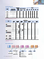
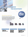
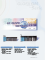
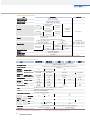
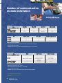
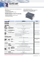
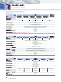
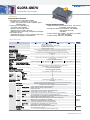
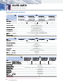
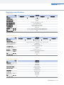
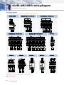
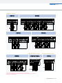
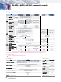
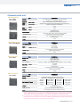
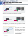
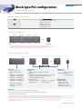
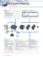
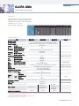
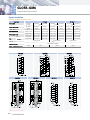
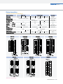
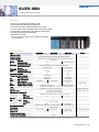
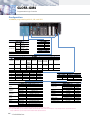
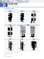
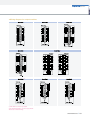
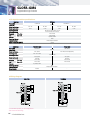
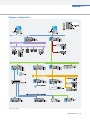
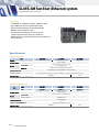
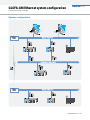
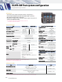
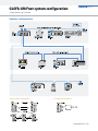
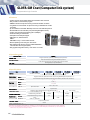
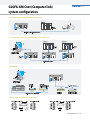
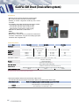
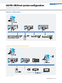
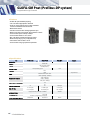
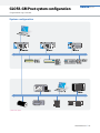
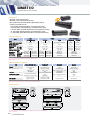
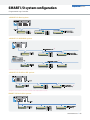
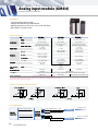
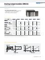
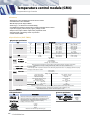
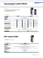
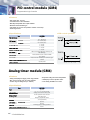
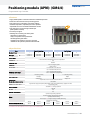
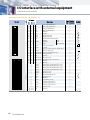
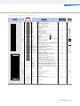
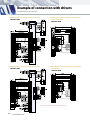
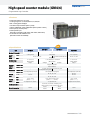
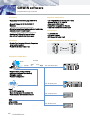
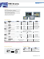
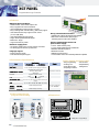
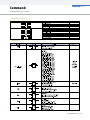
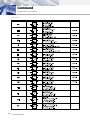
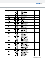
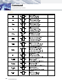
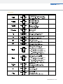
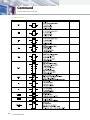
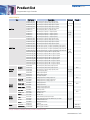
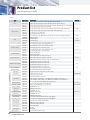
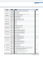
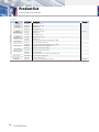
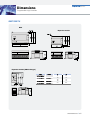
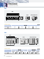
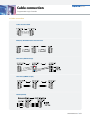
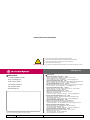


![[U4.84.01] Opérateur COMB_SISM_MODAL](http://vs1.manualzilla.com/store/data/006369926_1-bf5f185851d150b3bc2e73af807f0eaf-150x150.png)

![[U4.84.01] Opérateur COMB_SISM_MODAL](http://vs1.manualzilla.com/store/data/006354551_1-0a996585a4efb054f257f659270030c7-150x150.png)