1
GLOFA-GM4
Programmable Logic Controllers
y Read this manual carefully before installing, wiring, operating, servicing or inspecting this equipment.
y Keep this manual within easy reach for quick reference.
SAFETY INSTRUCTIONS
To Prevent injury and property damage, follow these instructions.
Incorrect operation due to ignoring instructions will cause harm or
damage, the seriousness of which is indicated by the following symbols.
DANGER
This symbol indicates the instant death or
serious injury if you don’t follow instructions
WARNING
This symbol indicates the possibility of
death or serious injury
CAUTION
This symbol indicates the possibility of
injury or damage to property.
■ The meaning of each symbol on equipment is as followed
This is the safety alert symbol.
Read and follow instructions carefully to avoid dangerous situation.
This Symbol alerts the user to the presence of “dangerous voltage”
Inside the product that might cause harm or electric shock.
SAFETY INSTRUCTIONS
Design Precautions
Warning
Install a safety circuit external to the PLC that keeps the entire system
safe even when there are problems with the external power supply or
the PLC module. Otherwise, serious trouble could result from
erroneous output or erroneous operation.
- Outside the PLC, construct mechanical damage preventing interlock
circuits such as emergency stop, protective circuits, positioning upper
and lower limits switches and interlocking forward/reverse operation.
When the PLC detects the following problems, it will stop calculation and
turn off all output in the case of watchdog timer error, module interface
error, or other hardware errors.
However, one or more outputs could be turned on when there are
problems that the PLC CPU cannot detect, such as malfunction of output
device (relay, transistor, etc.) itself or I/O controller. Build a fail safe
circuit exterior to the PLC that will make sure the equipment operates
safely at such times. Also, build an external monitoring circuit that will
monitor any single outputs that could cause serious trouble.
Make sure all external load connected to output does NOT exceed the
rating of output module.
Overcurrent exceeding the rating of output module could cause fire, damage
or erroneous operation.
Build a circuit that turns on the external power supply when the PLC
main module power is turned on.
If the external power supply is turned on first, it could result in erroneous
output or erroneous operation.
SAFETY INSTRUCTIONS
Design Precautions
Caution
Do not bunch the control wires or communication cables with the main
circuit or power wires, or install them close to each other. They should
be installed 100mm (3.94inch) or more from each other.
Not doing so could result in noise that would cause erroneous operation.
Installation Precautions
Caution
Use the PLC in an environment that meets the general specification
contained in this manual or datasheet.
Using the PLC in an environment outside the range of the general
specifications could result in electric shock, fire, erroneous operation, and
damage to or deterioration of the product.
Completely turn off the power supply before loading or unloading the
module.
Not doing so could result in electric shock or damage to the product.
Make sure all modules are loaded correctly and securely.
Not doing so could cause a malfunction, failure or drop.
Make sure I/O and extension connector are installed correctly.
Poor connection could cause an input or output failure.
When install the PLC in environment of much vibration, be sure to
insulate the PLC from direct vibration.
Not doing so could cause electric shock, fire, and erroneous operation.
Be sure to there are no foreign substances such as conductive debris
inside the module.
Conductive debris could cause fires, damage, or erroneous operation.
SAFETY INSTRUCTIONS
Wiring Precautions
Warning
Completely turn off the external power supply when installing or
placing wiring.
Not doing so could cause electric shock or damage to the product.
Make sure that all terminal covers are correctly attached.
Not attaching the terminal cover could result in electric shock.
Caution
Be sure that wiring is done correctly be checking the product’s rated
voltage and the terminal layout.
Incorrect wiring could result in fire, damage, or erroneous operation.
Tighten the terminal screws with the specified torque.
If the terminal screws are loose, it could result in short circuits, fire, or
erroneous operation.
Be sure to ground the FG or LG terminal to the protective ground
conductor.
Not doing so could result in erroneous operation.
Be sure there are no foreign substances such as sawdust or wiring
debris inside the module.
Such debris could cause fire, damage, or erroneous operation.
SAFETY INSTRUCTIONS
Startup and Maintenance Precautions
Warning
Do not touch the terminals while power is on.
Doing so could cause electric shock or erroneous operation.
Switch all phases of the external power supply off when cleaning the
module or retightening the terminal or module mounting screws.
Not doing so could result in electric shock or erroneous operation.
Do not charge, disassemble, heat, place in fire, short circuit, or solder
the battery.
Mishandling of battery can cause overheating or cracks which could result in
injury and fires.
Caution
Do not disassemble or modify the modules.
Doing so could cause trouble, erroneous operation, injury, or fire.
Switch all phases of the external power supply off before mounting or
removing the module.
Not doing so could cause failure or malfunction of the module.
Use a cellular phone or walky-talky more than 30cm (11.81 inch) away
from the PLC
Not doing so can cause a malfunction.
Disposal Precaution
Caution
When disposing of this product, treat it as industrial waste.
Not doing so could cause poisonous pollution or explosion.
◎
Chapter 1.
CONTENTS
◎
INTRODUCTION
1.1 Guide to User’s Manual ·························································································· 1 - 1
1.2 Features·············································································································· 1 - 2
1.3 Terminology ·········································································································1 – 4
Chapter 2. SYSTEM CONFIGURATION
2.1 Overall Configuration······························································································ 2 - 1
2.2 System Configuration Component Units List································································ 2 - 2
2.2.1 GM4 series Configuration ················································································ 2 - 2
2.3 System Configuration Types ···················································································· 2 - 6
2.3.1 Basic System································································································ 2 - 6
2.3.2 Computer Link System···················································································2 - 10
2.3.3 Network System ···························································································2 - 11
Chapter 3. GENERAL SPECIFICATION
3.1 General Specifications ··························································································3 – 1
Chapter 4. CPU MODULE
4.1 Performance Specifications ····················································································· 4 - 1
4.2 Parts Name and Decriptions ···················································································· 4 - 2
4.3 Operation processing ····························································································· 4 - 4
4.3.1 Operation processing Methods ········································································· 4 - 4
4.3.2 Operation processing at momentary power failure occurrence ································· 4 - 5
4.3.3 Scan Time···································································································· 4 - 6
4.3.4 Scan Watchdog Timer····················································································· 4 - 7
4.3.5 Timer processing ··························································································· 4 - 8
4.3.6 Counter processing ······················································································· 4 -10
4.4 Program ·············································································································4 - 12
4.4.1 Program Configuration ···················································································4 - 12
4.4.2 Program Execution Procedures········································································ 4 -13
4.4.3 Task··········································································································· 4 -16
4.4.4 Error Handling······························································································ 4 -22
4.4.5 Precautions when using special modules ··························································· 4 -23
4.5 Operation Modes·································································································· 4 -29
4.5.1 RUN mode ·································································································· 4 -29
4.5.2 STOP mode································································································· 4 -30
4.5.3 PAUSE mode······························································································· 4 -30
4.5.4 DEBUG mode ······························································································ 4 -30
4.5.5 Operation Mode Change ················································································ 4 -31
4.5.6 System Starting Method ················································································· 4 -32
4.6 Functions············································································································ 4 -34
4.6.1 Restart mode ······························································································· 4 -34
4.6.2 Self-diagnosis ······························································································ 4 -36
4.6.3 Clock function ······························································································ 4 -36
4.6.4 Remote function ··························································································· 4 -37
4.6.5 I/O Force On/Off function················································································ 4 -38
4.6.6 Direct I/O Operation function ··········································································· 4 -39
4.6.7 History Log-In ······························································································ 4 -39
4.6.8 External Device Error Diagnosis function ···························································4 –40
4.7 GM4-CPUC Dedicated Functions············································································· 4 -42
4.7.1 Error Mask function ······················································································· 4 -42
4.7.2 I/O Module Skip function ················································································ 4 -43
4.7.3 Online Module Changing Function ····································································4 –44
4.7.4 I/O Reservation Function ················································································4 –46
4.7.3 FEnet Reset Function ····················································································4 –47
4.7 Memory Configuration ··························································································· 4 -48
4.8 I/O No. Allocation Method·······················································································4 –50
Chapter 5. BATTERY
5.1 Specifications ······································································································· 5 - 1
5.2 Precautions for Use ······························································································· 5 - 1
5.3 Battery Replacement······························································································5 – 1
Chapter. 6 MEMORY MODULE AND BUILT-IN FLASH MEMORY
6.1 GM4-CPUA (Using Memory Module) ·········································································· 6 -1
6.1.1 Memory Module······························································································ 6 -1
6.1.2 Method of Writing A User Program to the Memory Module ······································· 6 -2
6.1.3 Operation Method ··························································································· 6 -3
6.2 GM4-CPUB (Using Built-in Flash Memory)··································································· 6 -4
6.2.1 Operation Mode Setting ··················································································· 6 -4
6.2.2 Starting Program in the Built-in Flash Memory And Operation Method ························ 6 -4
6.3 GM4-CPUC (Using Built-in Flash Memory)··································································· 6 -6
6.3.1 Program Storing Method by Using Built-in Flash Memory········································· 6 -6
6.3.2 Setting Operation Mode ··················································································· 6 -9
6.3.3 Upload Program Storing Method by Using Built-in Flash Memory ····························· 6 –9
Chapter. 7 INPUT AND OUTPUT MODULES
7.1 Notes on Selecting Input and Output Modules ····························································· 7 - 1
7.2 Digital Input Module Specifications ············································································ 7 - 2
7.2.1 16-point 12/24VDC input module (source/sink type) ·············································· 7 - 2
7.2.2 16-point 12/24VDC input module (source type)····················································· 7 - 3
7.2.3 32-point 12/24VDC input module (source/sink type) ·············································· 7 - 4
7.2.4 32-point 12/24VDC input module (source type)····················································· 7 - 5
7.2.5 16-point 24VDC input module (source/sink type)··················································· 7 - 6
7.2.6 32-point 24VDC input module (source/sink type)··················································· 7 - 7
7.2.7 64-point 12/24VDC input module (source/sink type) ·············································· 7 - 8
7.2.8 16-point 110VAC input module·········································································· 7 - 9
7.2.9 16-point 220VAC input module········································································· 7 -10
7.2.10 Interrupt input module ···················································································7 -11
7.3 Digital Output Module Specifications········································································· 7 -12
7.3.1 16-point relay output module ··········································································· 7 -12
7.3.2 16-point transistor output module (sink type) ······················································· 7 -13
7.3.3 16-point transistor output module (source type) ··················································· 7 -14
7.3.4 32-point transistor output module (sink type) ······················································· 7 -15
7.3.5 32-point transistor output module (source type) ··················································· 7 -16
7.3.6 64-point transistor output module (sink type) ······················································· 7 -17
7.3.7 16-point triac output module ············································································ 7 -18
7.4 Digital Input / Output Hybrid Module Specifications ······················································ 7 -19
7.4.1 8-point 12/24VDC input and 8-point relay output module ······································· 7 -19
7.4.2 8-point 12/24VDC input and 8-point transistor output module··································7 –20
Chapter 8. POWER SUPPLY MODULE
8.1 Selection of power supply module ············································································· 8 - 1
8.2 Specifications ······································································································· 8 - 3
8.3 Names of Parts ·····································································································8 – 5
Chapter 9. BASE BOARD AND EXPANSION CABLE
9.1 Specifications ······································································································· 9 - 1
9.1.1 Main Base Board ························································································· 9 - 1
9.1.2 Expansion Base Board···················································································· 9 - 2
9.1.3 Expansion Cable ··························································································· 9 - 2
9.2 Names of Parts ····································································································· 9 - 3
9.2.1 Main Base Board ························································································· 9 - 3
9.2.2 Expansion Base Board····················································································9 – 3
Chapter 10. INSTALLATION AND WIRING
10.1 Installation········································································································· 10- 1
10.1.1 Installation Environment ··············································································· 10- 1
10.1.2 Handling Instructions ··················································································· 10- 4
10.1.3 Mounting And Dismounting of Module······························································ 10- 7
10.2 Wiring ··············································································································· 10-9
10.2.1 Power Supply Wiring····················································································· 10-9
10.2.2 Input and Output Devices Wiring ····································································10-11
10.2.3 Grounding ·································································································10-11
10.2.4 Cable Specification for wiring ·········································································10-12
Chapter 11. MAINTENANCE
11.1 Maintenance and Inspection ···················································································11- 1
11.2 Daily Inspection ···································································································11- 1
11.3 Periodic Inspection ·······························································································11- 2
Chapter 12. TROUBLESHOOTING
12.1 Basic Procedures of Troubleshooting ···································································· 12- 1
12.2 Troubleshooting·································································································· 12- 1
12.2.1 Troubleshooting flowchart used when the POWER LED turns OFF ······················· 12- 2
12.2.2 Troubleshooting flowchart used when the STOP LED is flickering ·························· 12- 3
12.2.3 Troubleshooting flowchart used when the RUN and STOP LEDs turn off ··············· 12- 4
12.2.4 Troubleshooting flowchart used when the output load of the
output module does not turn on ······································································ 12- 5
12.2.5 Troubleshooting flowchart used when a program
cannot be written to the CPU module······························································· 12- 6
12.3 Troubleshooting Questionnaire ·············································································· 12- 7
12.4 Troubleshooting Examples···················································································· 12- 8
12.4.1 Input circuit troubles and corrective actions ······················································· 12- 8
12.4.2 Output circuit troubles and corrective actions····················································· 12- 9
12.5 Error Code List···································································································12-11
APPENDICES
Appendix 1. System Definitions ·············································································· APP 1 - 1
Appendix 2. Flag List···························································································· APP 2 - 1
Appendix 3. Function/Function Block List·································································· APP 3 - 1
Appendix 4. Dimensions
···················································································· APP 4 - 1
Chapter 1. INTRODUCION
Chapter 1.
INTRODUCTION
1.1 Guide to User’s Manual
This User’s Manual gives the specifications, performance and handling instructions for each of the necessary
units of the GLOFA-GM4 series PLC system.
The configuration of the User’s Manual is given below.
No
Title
Content
Chapter 1
Introduction
Chapter 2
System Configuration
Chapter 3
General Specifications
Chapter 4
CPU Module
Chapter 5
Battery
Chapter 6
Memory Module
Chapter 7
Digital I/O Module
Chapter 8
Power Supply Module
Chapter 9
Base Unit and
Extension Cable
Chapter 10
Installation and Wiring
Chapter 11
Maintenance
Chapter 12
Troubleshooting
Appendix 1
System Definitions
Describes parameter setting for basic I/O module and communications
module.
Appendix 2
Function/
Function Block List
Describes the types and processing time of function/function block.
Appendix 3
Flag List
Appendix 4
Outer Dimensions
Describes configuration of this manual, units’ features and terminology.
Describes available units and system configurations in the GLOFA-GM4
series.
Describes general specifications of various units used in the GLOFAGM4 series.
Describes the performance, specifications and functions of the CPU
module.
Describes the specifications and handling instructions for other modules
except for the CPU module.
Describes installation, wiring and handling instructions for reliability of
the PLC system.
Describes the check items and method for long term normal operation of
the PLC system.
Describes various operation errors and corrective actions.
Describes the types and content of various flags,
Shows outer dimensions of the CPU, I/O module and base unit.
REMARK
1) This manual does not describes the special/communications module and programming for them.
For their own functions, refer to the related User’s Manual.
1-1
Chapter 1. INTRODUCION
1.2 Features
1) GLOFA-GM series features:
(1) Design on the basis of international standard specifications(IEC 1131-3)
• Easy programming device support.
• Languages in compliance with IEC1131-3 are given. (IL/ LD / SFC)
(2) Open network by use of communications protocol in compliance with international standard specifications.
(3) High speed processing with an operation-dedicated processor included.
(4) Various special modules that enlarge the range of application of the PLC.
2) GM4-CPUA features :
(1) High speed operation processing
High speed processing of 0.2 ㎲/step with an operation-dedicated processor included.
(2) Heightened Self-diagnosis
Cause of errors is easily found as error codes has been more divided in accordance with their contents.
(3) Restart mode setting
The User can set Cold/Warm/Hot restart mode in accordance with the environment. Especially, the User
can set a allowed time in the Hot restart mode for exact control of the process.
Allowed Time of Power failure (Maximum : 23h 59m 59s)
(4) Debug operation
On-line debugging is available if the PLC operation mode is set to debug operation mode.
Debugging functions :
• Executed by one instruction.
• Executed by the break-point settings
• Executed by the device status
• Executed by the specified scan times
(5) Various Program Executions
Time driven task, external and internal contact task programs as well as scan program can be executed by
setting the execution condition. The user can set variously the program execution mode.
(6) On-line Program Editing
On-line Program Editing is available, therefore the user can test systems easily after it is set up.
(7) Various instruction support
GLOFA PLC can support additional instructions steadily without changing CPU module.
• Various Functions and Function Blocks are supported for various applications.
• User can make great instruction groups through making out user’s own functions and function blocks.
1-2
Chapter 1. INTRODUCION
3) GM4-CPUB features
GM4-CPUB has the same features with GM4-CPUA, and also it has its own features as follow.
(1) Built-in flash memory
GM4-CPUB has a 512kb built-in flash memory for upload program.
(2) Communication module
Up to 4 communication modules (GM4-CPUA : 2 modules) can be mounted.
(3) Communication modules on expansion base board
Communication module can be mounted on an expansion base board.
4) GM4-CPUC features
GM4-CPUC has the same features with GM4-CPUA, and also it has its own features as follow.
(1) High speed processing
Operation processing of GM4-CPUC is faster than GM4-CPUA/B
• GM4-CPUA/B : 0.2 ㎲/step.
• GM4-CPUC : 0.12 ㎲/step.
(2) Expanded User Program Capacity
GM4-CPUC has 1M byte program capacity which is bigger than GM4-CPUA/B (128k byte).
(3) Communication module
Up to 4 communication modules (8 modules of Cnet) can be mounted.
(Refer to 2.3.3 Network System for details.)
(4) Flexible Application of Cnet Module
GM4-CPUA/B do not support Cneet Module in expanded base module, however Cnet Module can be
mounted on expanded base module in GM4-CPUC. (Refer to 2.3.2 Cnet I/F System for details.)
(5) Flash Memory Writing is available in On-line Editing.
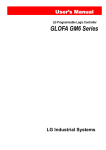
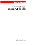
(6) High Speed Communication with GMWIN using USB.
GM4-CPUC can support Maximum 115.2kbps using RS-232C, and also it can support 12Mbps using USB.
User can decrease Program Writing/Reading and Monitoring Time using USB
Downloading Time of 100k Byte Program
USB(GM4-CPUC)
3.5
18
RS-232C(GM4-CPUC)
Unit (s)
(7) Maximum 6 expanded base modules are available.
GM4-CPUC supports Maximum 6 expanded base modules using high-performance base modules.
Therefore, Maximum 56 I/O modules can be mounted. Expanding distance is maximum 15 m.
(8) GM4-CPUC can be supported in GMWIN Ver 4.0 or over.
1-3
Chapter 1. INTRODUCION
1.3 Terminology
The following table gives definition of terms used in this manual.
Terms
Module
Unit
PLC system
Cold Restart
Warm Restart
Definition
Remarks
Example)
A standard element that has a specified function which configures
CPU module
the system. Devices such as I/O board, which inserted onto the
Power Supply module
mother board or base unit.
I/O module
A module or a module group which is a minimum element to Example)
operate and organizes PLC system, and is connected with other Main Unit
modules or other module groups
Expansion Unit
A system which consists of the PLC and peripheral devices. A user
program can control the system.
To restart the PLC system and user programs after all of the
data(Variables and programs of I/O image area, of internal register,
of timer of counter) were set to the specified conditions
automatically or manually.
In the warm restart mode, The power supply Off occurrence will be
informed to the user program and the PLC system restarts with the
previous user-defined data and user program after the power
supply Off.
Hot Restart
After a power supply Off, the PLC system return all of the data to
the previous status within maximum allowed time and restarts.
I/O Image Area
Internal memory area of the CPU module which used to hold I/O
statuses.
Watch Dog Timer
Supervisors the pre-set execution times of programs and warns if a
program is not completed within the pre-set time.
Function
Operation Unit which outputs immediately its operation result of an
input, while four arithmetic operations comparison operation store
their results in the inside of instructions.
Function Block
Operation Units which store operation result in the inside of
instruction such as timer and counter and use the operation results
which have been stored through many scans.
Direct Variable
Example)
Variables used without separate declaration of names and type. • %IX0.0.2
I.Q.M area correspond to this variable
• %QW1.2.1
• %MD1234
1-4
Chapter 1. INTRODUCION
Terms
Definition
Symbolic
Variable
Variables used after the user’s definition of their names and types.
Declarations as ‘INPUT_0’ = %IX0.0.2, ‘RESULT = %MD1234’ makes
INPUT_0 and RESULT be able to used instead of %IX0.0.2 and %MD123
in programming.
GMWIN
A peripheral device for the GLOFA-GM series. It executes program
creation, edit, compile and debugging.
FAM
Abbreviation of the word ‘Factory Automation Monitoring S/W’. It is used to
call S/W packages for process supervision.
Task
It means startup conditions for a program. There are three types of plus
cycle task, internal junction task and external junction task. External
junction task starts by the input signals of external input modules.
RTC
Abbreviation of the word ‘Real Time Clock’. Used to call a general IC which
includes clock function.
Current flows in from the switch to the PLC input terminal if a input signal
turns on.
Sink Input
Current flows in from the PLC input terminal to the switch if a input signal
turns on.
Source
Input
Current flows in from the load to the output terminal if the PLC output
junction turn on.
Sink Output
Output
contact
1-5
Remarks
Chapter 1. INTRODUCION
Terms
Definition
Current flows in from the output terminal to the load if the PLC output junction
turn on.
Source Output
Output contact
Fnet
Fieldbus Network
Cnet
Computer Network
Enet
Ethernet Network
Mnet
Mini-MAP Network
Dnet
DeviceNet Network
Pnet
Profibus Network
ISA
Instrument Society of America
GM4C System
System which is combined by GM4-CPUC and high performance bases
(GM4-B4MH, GM4-B6MH, GM4-B8MH, GM4-B4EH, GM4-B6EH, GM4-B8EH)
(Refer to Chapter 2 for details)
1-6
Remarks
Chapter 2. SYSTEM CONFIGURATION
Chapter 2.
SYSTEM CONFIGURATION
The GLOFA-GM4 series have various units suitable to configuration of the basic, computer link and network systems.
This chapter describes the configuration and features of each system.
2.1 Overall Configuration
The following shows the overall configuration of the GLOFA-GM4 series.
G
RS-232C
Or
USB Cable
Battery
GMWIN
CPU Module
Power Module
(GM4-P□ □ □ )
Main Base (GM4-B0□ M, GM4-B□ MH)
I/O Module
(G4I(Q)-□ □ □ □ )
Expansion Cable (G4C-E□ □ □ )
Special Module
(G4F-□ □ □ □ )
Expansion Base (GM4-B0□ E, GM4-B□ EH)
Communication Module
(G4L-□ □ □ □ )
2-1
Diskettes
Chapter 2. SYSTEM CONFIGURATION
2.2 System Configuration Component Units List
The following table shows components units configuration of GLOFA-GM4 series.
2.2.1
GM4 series Configuration
Items
Models
Description
Remarks
GM4-CPUA • Maximum I/O points: 2,048
CPU module
GM4-CPUB • Maximum I/O points: 2,048
GM4-CPUC • Maximum I/O points: 3,584
G4I-D22A
• 16-point 12/24 VDC input module(current source/sink input)
G4I-D22B
• 16-point 12/24 VDC input module(current source input)
G4I-D22C • 16-point 24 VDC input module(current source/sink input)
Digital input
module
G4I-D24A
• 32-point 12/24 VDC input module(current source/sink input)
G4I-D24B
• 32-point 12/24 VDC input module(current source input)
G4I-D24C • 32-point 24 VDC input module(current source/sink input)
G4I-D28A
• 64-point 12/24 VDC input module(current source/sink input)
G4I-A12A
• 16-point 110 VAC input module
G4I-A22A
• 16-point 220 VAC input module
G4Q-RY2A • 16-point relay contact output module(2 A)
G4Q-TR2A • 16-point transistor output module(0.5 A, sink output)
G4Q-TR2B • 16-point transistor output module(0.5 A, source output)
Digital output
module
G4Q-TR4A • 32-point transistor output module(0.1 A, sink output)
G4Q-TR4B • 32-point transistor output module(0.1 A, source output)
G4Q-TR8A • 64-point transistor output module(0.1 A, sink output)
G4Q-SS2A • 16-point triac output module(1 A)
G4Q-SS4A • 16-point triac output module(0.6 A)
Input output
hybrid module
• 8-point 12/24 VDC input module(current source/sink input)
• 8-point relay contact output module(2 A)
• 8-point 12/24 VDC input module(current source/sink input)
G4H-DT2A
• 8-point transistor output module(0.5 A, sink output)
G4H-DR2A
GM4-PA1A Input 110 VAC
Power supply
module
GM4-PA2A Input 220 VAC
GM4-PA1B
GM4-PA2B
GM4-PA2C
GM4-PD3A
Input 110 VAC
Input 220 VAC
Input 220VAC
Input 24VDC
• 5VDC(1) : 4 A, 5VDC(2) : 1 A
• 24VDC : 0.7 A
• 5VDC : 3 A, 24VDC : 0.5 A
• 5VDC : 8 A
• 5VDC : 4 A
2-2
5 VDC(1) for I/O
modules
5 VDC(2)
for peripheral devices
Chapter 2. SYSTEM CONFIGURATION
Items
Models
Description
Remarks
GM4-B04M • Up to four modules can be mounted.
GM4-B4MH • Up to four modules can be mounted.(high performance module)
GM4-B06M • Up to six modules can be mounted.
Main base unit
GM4-B6MH • Up to six modules can be mounted.(high performance module)
GM4-B08M • Up to eight modules can be mounted.
GM4-B8MH • Up to eight modules can be mounted.(high performance module)
GM4-B12M • Up to twelve modules can be mounted.
expansion
impossible
GM4-B04E • Up to four modules can be mounted.
GM4-B4EH • Up to four modules can be mounted.(high performance module)
GM4-B06E • Up to six modules can be mounted.
Expansion base unit
GM4-B6EH • Up to six modules can be mounted.(high performance module)
GM4-B08E • Up to eight modules can be mounted.
GM4-B8EH • Up to eight modules can be mounted.(high performance module)
G4C-E041 • 0.4 m long
G4C-E061 • 0.6 m long
G4C-E121 • 1.2 m long
Expansion cable
G4C-E301 • 3.0 m long
G4C-E601 • 6.0 m long
G4C-E102 • 10.0 m long
G4C-E152 • 15.0 m long
Memory module
G4M-M032 • Flash memory (32Kstep)
2-3
For GM4-CPUA
only
Chapter 2. SYSTEM CONFIGURATION
Items
Models
G4F-AD2A
• Voltage/current input : 4 channels
• DC -5 to +5V / -10 to +10V / DC -20 to 20 mA
G4F-AD3A
• Voltage/current input : 8 channels
• DC 1 to 5V / 0 to 10V / DC 4 ~ 20 mA
A/D conversion module
D/A conversion module
High speed counter
module
Description
G4F-DA1A • Voltage/current output : 2 channels
• DC -10 to 10V / DC -4 to 20 mA
G4F-DA2V • Voltage/current output : 4 channels
• DC -10 to 10V
•
Current output : 4 channels
G4F-DA2I
• DC 4 to 20 mA
G4F-DA3V • Voltage output : 8 channels
• DC -10 to 10V
G4F-DA3I • Current output : 8 channels
• DC 4 to 20 mA
• Counting range: 0 to 16,777,215(24 bit binary)
G4F-HSCA
• 50 KHz, 1 channel
Remarks
24 bit binary
G4F-HO1A
• Counting range: -2,147,483,648 to 2,147,483,647
• 200 KHz, 2 channels
32 bit binary
G4F-HD1A
• Counting range: -2,147,483,648 to 2,147,483,647
• 500 KHz, 2 channels
32 bit binary
G4F-POPA • Pulse output, 1 axis control
G4F-POPB • Pulse output, 2 axis control
Special
modules
G4F-PP1O • Pulse output(Open Collector), 1 axis control
Positioning module
G4F-PP2O • Pulse output(Open Collector), 2 axis control
G4F-PP3O • Pulse output(Open Collector), 3 axis control
G4F-PP1D • Pulse output(Line Driver), 1 axis control
G4F-PP2D • Pulse output(Line Driver), 2 axis control
G4F-PP3D • Pulse output(Line Driver), 3 axis control
Thermocouple input
module
Temperature-measuring
resistor input module
PID control module
Process control module
• Temperature sensor: seven types(K, J, E, T, B, R or S)
• Input point: 4 channels
• Temperature sensor: Pt 100, Jpt 100
G4F-RD2A
• Input point: 4 channels
G4F-PIDA • Controls maximum 8 loops
G4F-TC2A
G4F-PIDB • Controls maximum 8 loops, Transistor output
• 2 channels of analog input
G4F-TMCA • 2 channels of analog/transistor output
• PID function
Analog timer module
• Timer point: 8 points
G4F-AT3A • Setting value range: 0.1 to 1.0 sec, 1 to 10 sec,
10 to 60 sec, 60 to 600 sec
Interrupt input module
G4F-INTA • Input point : 8 points
2-4
Setting
1 point each
Chapter 2. SYSTEM CONFIGURATION
Items
Fast Enet I/F module
Fast Dedicated-Enet I/F
module (Master)
Fast Dedicated-Enet I/F
module (Slave)
Fnet I/F module
Rnet I/F module
Models
G4L-EUTB
G4L-EUFB
G4L-EU5B
G4L-EUTC
G4L-EUFC
G4L-EU5C
G4L-ERTC
G4L-ERFC
G4L-ER5C
G4L-FUEA
GOL-FUEA
G4L-RUEA
Fnet remote I/F module G4L-RBEA
G0L-SMIA
G0L-SMQA
Standalone remote I/F
Commumodule
nications
modules
G0L-SMHA
G0L-AD3A
G0L-DA3I
Repeater
Optic converter
Active coupler
Computer link module
Enet I/F module
DeviceNet I/F module
Profibus-DP I/F module
Others
Pseudo input switch
Dust protection module
GOL-FREA
Description
• 10/100BASE-TX,UTP
• 100BASE-Fx, Fiber Optic
• 10BASE-5, AUI
• 10/100BASE-TX,UTP
• 100BASE-Fx, Fiber Optic
• 10BASE-5, AUI
• 10/100BASE-TX,UTP
• 100BASE-Fx, Fiber Optic
• 10BASE-5, AUI
• For Fnet I/F
• 1 Mbps base band
• For twisted cable
• For Rnet I/F
• For twisted cable
• For Fnet remote I/F
• For twisted cable
• 16-point 12/24 VDC input
• 16-point relay output (1 A)
• 8-point 12/24 VDC input
• 8-point relay output (1 A)
• Voltage/current input : 8 channels
• DC 1 to 5V / DC 0 to 10V / DC 4 to 20 mA
• Current output : 8 channels
• DC 4 to 20 mA
• For Fnet
GOL-FOEA • Optic/Electric converter
GOL-FAPA • Power supply board for active coupler
GOL-FABA • Base unit for active coupler
GOL-FACA • Card for active coupler
GOL-FADA • Dummy card for active coupler
G4L-CUEA • RD-232C / RS-422 : 1 channel for each
• Comply with IEEE 802.3
G4L-EUEA
• 10 Base 5 / 10 Base T
G4L-DUEA • DeviceNet I/F module
• Dnet slave module
G0L-DSIA • 16-point DC12/24V input
• Comply with ODVA 2.0
• Dnet slave module
G0L-DSQA • 16-point relay input
• Comply with ODVA 2.0
G4L-PUEA • Profibus-DP master module (I/O : 1K)
G4L-PUEB • Profibus-DP master module (I/O : 7K)
G4S-SW16 • 16-point pseduo switch for GM4 input
GM4-DMMA • Keeps unused slots from dust
2-5
Remarks
For GM4A/B O/S
Ver 2.7 or over
For GM4C O/S
Ver 2.0 or over
For mounting
inside computer
Chapter 2. SYSTEM CONFIGURATION
2.3 System Configuration Types
System configuration is classified into 3 types. First, Basic system that is configured with only basic and expansion
base units. Second, Computer link system that executes data communications between the CPU module and a
computer by use of a computer link module(G4L-CUEA). Third, Network system, which is used to control the PLC
and remote I/O modules.
2.3.1 Basic System
1) Existing Systems
The following describes basic system which is configured with a cable connection of only basic base units
and expansion base units. GM4 Series can be used CPU(GM4-CPUA,GM4-CPUB,GM4-CPUC) and Base
together.
Slots No.: 0
P
O
W
E
R
Example of System
Configuration
C
P
U
Slots No.: 0
P
O
W
E
R
3
1
2
3
1.2.0 1.3.0
∼
∼
1.2.15 1.3.15
4
4
5
6
7
0.4.0 0.5.0
∼
∼
0.4.15 0.5.15
0.6.0 0.7.0
∼
∼
0.6.15 0.7.15
5
7
6
1.4.0 1.5.0 1.6.0 1.7.0
∼
∼
∼
∼
1.4.15 1.5.15 1.6.15 1.7.15
Main Base
Base No.: 0
Expansion
Cable
Expansion
Base
Base No.: 1
1
2.0.0 2.1.0
∼
∼
2.0.15 2.1.15
Slots No.: 0
P
O
W
E
R
2
0.0.0 0.1.0 0.2.0 0.3.0
∼
∼
∼
∼
0.0.15 0.1.15 0.2.15 0.3.15
1.0.0 1.1.0
∼
∼
1.0.15 1.1.15
Slots No.: 0
P
O
W
E
R
1
1
3.0.0 3.1.0
∼
∼
3.0.15 3.1.15
2
3
4
5
6
7
2.2.0 2.3.0
∼
∼
2.2.15 2.3.15
2.4.0 2.5.0
∼
∼
2.4.15 2.5.15
2.6.0 2.7.0
∼
∼
2.6.15 2.7.15
2
4
6
3
5
3.2.0 3.3.0 3.4.0 3.5.0
∼
∼
∼
∼
3.2.15 3.3.15 3.4.15 3.5.15
Base No.: 2
7
3.6.0 3.7.0
∼
∼
3.6.15 3.7.15
(The above figure shows the configuration where 16-input/output modules are loaded.
2-6
Expansion
Base
Expansion
Base
Base No.: 3
Chapter 2. SYSTEM CONFIGURATION
Maximum Number of Expansion
Stages
Three Stages
Maximum Expansion Distance
3m
Maximum number of Input/Output
modules
32 modules
Maximum number of Input/Output
points
CPU module
Power Supply module
Basic Base Unit
Configuration Expansion Base Unit
units
Expansion Cable
I/O module
• 16-point module loaded : 512 points
• 32-point module loaded : 1,024 points
• 64-point module loaded : 2,048 points
GM4-CPUA/GM4-CPUB/GM4-CPUC
GM4-PA1/2A, GM4-PA1/2B,GM4-PD3A,GM4-PA2C
GM4-B04/06/08/12M, GM4-B4MH,/B6MH/B8MH
GM4-B04/06/08E, GM4-B4EH/B6EH/B8EH
G4C-E041/E121/E301
G4I-
G4Q-
G4F-
• 64 I/O points have been fixedly allocated for every slot in the base unit.
• 64 points are allocated to each slot in a base unit whatever it is empty or not.
• There's no limitation in the loading location and loading number of special modules,
• Special modules do not have fixed I/O numbers while a fixed I/O number is allocated to a digital I/O module.
• A dedicated function block controls a special module and memory is allocated automatically.
• The follow
figure
Slot No.
: shows
0 the
1 example
2 of3 I/O Address
4
5 assignment.
6
7
0
1
2
3
32 point Output
32 point Output
16 point Output
32 point Input
64 point Output
32 point Output
32 point Output
16 point Output
64 point Input
32 point Input
16 point Input
16 point Input
CPU
POWER
I/O number allocation
%QX 1.3.0 ~ 31
%QX 1.2.0 ~ 31
%QX 1.1.0 ~ 15
%IX 1.0.0 ~ 31
Base No. 1
2-7
Chapter 2. SYSTEM CONFIGURATION
2) GM4C System
GM4C System is the system which is organized with GM4-CPUC for CPU module, and high performance main
base(GM4-B4MH/B6MH/B8MH) and expansion base (GM4-B4EH/B6EH/B8EH).
Slot No. :
Example
CPU
Configuration
POWER
System
Slot No. :
0
0
1
2
0.0.0 0.1.0
∼
∼
0.0.15 0.1.15
3
4
0.2.0 0.3.0
∼
∼
0.2.15 0.3.15
5
6
0.4.0 0.5.0
∼
∼
0.4.15 0.5.15
7
0.6.0 0.7.0
∼
∼
0.6.15 0.7.15
Main Base
(High Performance)
Base No. 0
Expansion Calbe
POWER
Slot No. :
POWER
Slot No. :
POWER
Slot No. :
POWER
Slot No. :
POWER
Slot No. :
1
1.0.0 1.1.0
∼
∼
1.0.15 1.1.15
2
3
1.2.0 1.3.0
∼
∼
1.2.15 1.3.15
4
5
1.4.0 1.5.0
∼
∼
1.4.15 1.5.15
6
7
1.6.0 1.7.0
∼
∼
1.6.15 1.7.15
Group Setting
Jumper (Group 0)
Expansion Base
(High Performance)
Base No. 1
0
1
2.0.0 2.1.0
∼
∼
2.0.15 2.1.15
2
3
2.2.0 2.3.0
∼
∼
2.2.15 2.3.15
4
5
2.4.0 2.5.0
∼
∼
2.4.15 2.5.15
6
7
2.6.0 2.7.0
∼
∼
2.6.15 2.7.15
Expansion Base
(High Performance)
Base No. 2
0
1
3.0.0 3.1.0
∼
∼
3.0.15 3.1.15
2
3
3.2.0 3.3.0
∼
∼
3.2.15 3.3.15
4
5
3.4.0 3.5.0
∼
∼
3.4.15 3.5.15
6
7
3.6.0 3.7.0
∼
∼
3.6.15 3.7.15
Expansion Base
(High Performance)
Base No. 3
0
1
4.0.0 4.1.0
∼
∼
4.0.15 4.1.15
2
3
4
5
6
7
4.2.0 4.3.0 4.4.0 4.5.0 4.6.0 4.7.0
∼
∼
∼
∼
∼
∼
4.2.15 4.3.15 4.4.15 4.5.15 4.6.15 4.7.15
Group Setting
Jumper(Group 1)
Expansion Base
(High Performance)
Base No. 4
0
1
5.0.0 5.1.0
∼
∼
5.0.15 5.1.15
2
3
5.2.0 5.3.0
∼
∼
5.2.15 5.3.15
4
5
5.4.0 5.5.0
∼
∼
5.4.15 5.5.15
6
7
5.6.0 5.7.0
∼
∼
5.6.15 5.7.15
Expansion Base
(High Performance)
Base No. 5
0
1
POWER
6.0.0 6.1.0
∼
∼
6.0.15 6.1.15
2
3
6.2.0 6.3.0
∼
∼
6.2.15 6.3.15
4
5
6.4.0 6.5.0
∼
∼
6.4.15 6.5.15
6
7
6.6.0 6.7.0
∼
∼
6.6.15 6.7.15
Expansion Base
(High Performance)
Base No. 6
(I/O No. is for example when to load 16point module.)
2-8
Chapter 2. SYSTEM CONFIGURATION
Maximum Number of
Expansion Stages
Maximum Expansion
Distance
Maximum number of
Input/Output modules
Maximum number of
Input/Output points
Configuration
units
6 Stages
15 m
56 Modules
• 16-point module loaded : 896 points
• 32-point module loaded : 1,792 points
• 64-point module loaded : 3,584 points
CPU
Module
GM4-CPUC
Power
Module
GM4-PA1/2A,GM4-PD3A,GM4-PA2C
Main Base
GM4-B4MH/B6MH/B8MH
Expansion
Base
GM4-B4EH/B6EH/B8EH
Expansion
Cable
G4C-E041/E061/E121/E301/E601/E102/E152
I/O
Module
G4I-□□□□
G4Q-□□□□
G4F-□□□□
• 64 I/O points have been fixedly allocated for every slot in the base unit.
• 64 points are allocated to each slot in a base unit whatever it is empty or not.
• There's no limitation in the loading location and loading number of special modules,
• Special modules do not have fixed I/O numbers while a fixed I/O number is allocated to a digital I/O module.
• A dedicated function block controls a special module and memory is allocated automatically.
• IO Parameter must be same with actual mounted I/O Module. If not, the PLC does not start running.
• High performance expansion bases (GM4-B4EH/GM4-B6EH/GM4-B8EH) are separated by Group ‘0’ and ‘1’.
Groups are set up by jumps on expansion bases. Initial group setting is Group ‘0’.
I/O number allocation
* Setting Group Jumper Pins
Group ‘0’ Setting
Group ‘1’ Setting
REMARK :
1) Main base No. is fixed to No. 0, and expansion base No. is assigned to 1, 2, 3 as sequence.
(In case of high performance base, jumpers must be set to group ‘0’.)
2) In case of installing expansion base 4 stages or over of GM4C System, install expansion base additionally,
and then jumps of additional expansion base must be set to group ‘1’. In this case, those expansion bases
are assigned to 4, 5, 6 as sequence.
2-9
Chapter 2. SYSTEM CONFIGURATION
2.3.2 Computer Link System
Computer Link System communicates data between the CPU module and peripheral devices like a
computer or a printer by use of RS-232C and RS-422(or RS-485)interface of the computer link module. The
G4L-CUEA is the computer link module for GM4 series. For details of computer link module, refer to related
User's Manual.
REMARK :
1) The follow shows the possible mounting number of computer link module and possibility of mounting on
expansion base as CPU models.
Items
GM4-CPUA
GM4-CPUB
GM4-CPUC
The Possible mounting number
of Computer Link Module
4
4
8
2 - 10
Possibility of mounting on
expansion base.
X
O
O
Chapter 2. SYSTEM CONFIGURATION
2.3.3 Network System
The Network system adapted in the GLOFA series is a Fnet system that satisfies the IEC/ISA field bus
specifications. Fnet system as a network system is used for data communications between CPU modules
and control of remote I/O modules so that distribution of control and concentration of supervision could be
easy. And also, as user’s needs, Ethernet I/F system, DeviceNet I/F system or Profibus I/F system could be
built. For details, refer to Fnet system user's manual.
1) System Configuration
• Maximum 3 stages of expansion bases could be used in each of remote systems.
Fnet I/F Module
Main Base
G4L−FUEA
GM4−CPUA
GM4−PA2A
In these slots, the network modules are not available to
G4L−RBEA
GM4−PA2A
Main Base
Fnet Remote I/F Module
2) In case of installing remote system by Fnet remote I/F module, the installing method is same with existing
system, however the follow modules are not available.
Section
Special Module
Name
Items
PID Control Module
G4F-PIDA/ PIDB
Process Control Module
G4F-TMCA
G4F-POPA/POPB
Position Module
G4F-PP1O/2O/30
G4F-PP1D/2D/3D
Analog Timer Module
G4F-AT3A
Fnet I/F Module
G4L-FUEA
Computer Link I/F Module
G4L-CUEA
DeviceNet I/F Module
G4L-DUEA
Profibus I/F Module
Communication Module
G4L-PUEA
G4L-PUEB
Ethernet I/F Module
G4L-EUEA
Rnet I/F Module
G4L-RUEA
Fast Enet I/F Module
G4L-EUTB/EUFB/EU5B
Fast Dedicated-Enet I/F Module (Master)
G4L-EUTC/EUFC/EU5C
Fast Dedicated-Enet I/F Module (Slave)
G4L-ERTC/ERFC/ER5C
2 - 11
Chapter 2. SYSTEM CONFIGURATION
3) The follow shows the possible mounting number of Fnet I/F module and possibility of mounting on
expansion base as CPU models
Items
The Possible mounting number
of Fnet Module
Possibility of mounting on
expansion base.
GM4-CPUA
2
X
GM4-CPUB
4
O
GM4-CPUC
8
O
4) Assignment of Input / Output
(1) Variables of remote input/output could be assigned by high speed link parameter.
(2) Input/output variable or internal variable could be assigned for input/output
(3) Maximum points of input/output variables are as follow
• GM4C : 32,000 points ( when to use 64 point module )
%IX0.0.0 to %IX63.7.63,
%QX0.0.0 to %QX63.7.63
5) Assignment of Input / Output in the Remote System Configuration
• Assignment of input/output in the remote system configuration is same with basic input/output system.
For example, if it is assigned to starting address %IX12.0.0 and 32 word size for receiving data of remote 12
stage in the high speed parameter, and starting address %QX12.0.0 and 32 word size for sending data,
12 stage remote base is assigned input/output number in the same way to assign base No.12 of basic system
configuration.
6) Base Expansion of Remote Stage
• If the size of Rx/Tx data is assigned to ’64 words’, it is assigned to %IX0.0.0 to %IX0.7.63, %QX0.0.0
to %Qx0.7.63 in the 12 stage base, and also it is assigned to %IX3.0.0 to %IX3.7.63, %QX3.0.0
to %QX3.7.63 in the 12 stage expansion base.
REMARK :
1) Pay attention not to overlap sections when to assign remote stage number and area
2) Only in case of assigning the Input/output by input/output variable(%IW,%QW), it can support input/output
service such as I/O Forcing.
Pay attention to assign input/output using internal variable (%MW).
2 - 12
Chapter 3. GENERAL SPECIFICATIONS
Chapter 3. General Specifications
3.1 General specifications
The following shows the general specifications of the GLOFA-GM series.
No
1
2
3
4
5
6
7
8
9
10
11
Item
Operating ambient
temperature
Storage ambient
temperature
Operating ambient
humidity
Storage ambient
humidity
Vibration
Shocks
Noise Immunity
Operating
ambience
Altitude
Pollution
Cooling method
Specifications
References
0 ~ 55 °C
-25 ~ +75 °C
5 ~ 95%RH, non-condensing.
5 ~ 95%RH, non-condensing.
Occasional vibration
Acceleration
Amplitude
Sweep count
0.075 mm
9.8 m/s 2{1 G}
10 times per
Continuous vibration
axis,
Frequency
Acceleration
Amplitude
on X,Y, Z axis
0.035 mm
10≤f <57 Hz
2
4.9 m/s {0.5G}
57≤f≤150 Hz
Maximum shock acceleration: 147 m/s2{15G}
Duration time: 11 ms
Pulse wave: half sine pulse (3 shocks per axis, on X,Y,Z axis)
Square wave
± 1,500 V
Impulse Noise
Electronic
Voltage : 4 kV (contact discharge)
discharge
Radiated
electromagnetic field
27 ~ 500 MHz, 10 V/m
noise
Digital I/O
Power
Digital I/O
(<24V)
Item
Fast transient/burst
supply
(>24V)
Analog I/O
noise
interface
Voltage
2 kV
1 kV
0.25 kV
Frequency
10≤ f<57 Hz
57≤f≤150 Hz
Free of corrosive gases and excessive dust.
IEC 61131-2
IEC 61131-2
IEC 61131-2,
IEC 801-3
IEC 61131-2,
IEC 801-3
IEC 61131-2,
IEC 801-4
IEC 61131-2
2,000 m or less
2
Air-cooling
Hint :
1) IEC(International Electromechanical Commission) : An international civilian institute who establishes
international standards in area of electric's and electronics.
2)Pollution : An indicator which indicates pollution degree which determine insulation performance of equipment.
Pollution 2 means that nonconductive pollution usually occurs but temporal conduction occurs with condensing
3-1
Chapter 4. CPU module
Chapter 4. CPU Module
4.1 Performance Specifications
The following shows the general specifications of the GM4 CPU module.
Specifications
GM4-CPUA(B)
GM4-CPUC
Items
Operation method
Cyclic operation of stored program, Interrupt task operation
I/O control method
Scan synchronous batch processing method (Refresh method)
Programming language
Ladder Diagram
Instruction List
Sequential Function Chart
Operator
Number of
instructions
Basic function
194
Basic function block
11
21
194 + Floating Point Arithmetic
Function
Special function block
82
62
Operator
0.2 µs / instruction
0.12 µs / instruction
0.2 µs / Step
0.12 µs / Step
Programming memory capacity
128K byte
Max. I/O points
2048 points
1M byte
3,584 points
Max. I/O points memory mapping area
4,096(8,192) points
32,768 points
Processing
speed
Basic function
Basic function block
Data memory
Remarks
Direct variable area
4 to 32K byte
8 to 64K byte
Symbolic variable area
54(50)K byte - Direct variable area
428K byte – Direct variable area
Timer
No limitations in points.
Time range : 0.001 to 4,294,967.295 sec(1,193 hours)
1 point occupies 20 bytes
of symbolic variable area.
Counter
No limitations in points
Counting range : -32,768 to +32,767
1 point occupies 8 bytes
of symbolic variable area.
Program
types
Numbers of program blocks
180
Initialization programs
2 (_INT, _H_INIT)
Task
Programs
Time driven tasks
External interrupt
tasks
Internal task
Error task
8
32
8
16
-
1 (_ERR_SYS)
Operation modes
RUN, STOP, PAUSE and DEBUG
Restart modes
Cold, Warm, Hot Restart
Self-diagnostic functions
Watch dog timer, Memory error detection, I/O error detection, Battery
error detection, Power supply error detection, etc.
Data protection method at power failure
Set to 'Retain' variables at data declaration.
Maximum extension stages
3
6
Internal current consumption
130mA
700mA
Weight
0.25 Kg
0.23 Kg
4-1
Chapter 4. CPU module
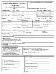
4.2 Parts Name and Descriptions
①
GM4-CPUA
RUN
STOP
PAU/REM
RUN
STOP
②
③
GM4-CPUB
GM4-CPUC
RUN
STOP
PAU/REM
STOP
RUN
PAU/REM
RUN
STOP
RUN
STOP
④
⑥
⑨
⑧
⑦
⑤
< GM4-CPUA >
No.
< GM4-CPUB >
Name
< GM4-CPUC >
Details
RUN LED
Indicator of CPU Operation Mode.
y On : In case of Key Switch is Local or Remote RUN Mode.
y Off : In below case, RUN LED is OFF.
In case of Power is supplied abnormally.
In case of Key Switch is STOP or PAU / REM Mode.
In case of occurrence of Error which stops operation.
STOP LED
y On : In case of Key Switch is Local or Remote STOP Mode.
y Off : In below case, STOP LED is OFF.
In case of Key Switch is Local RUN or Local Pause Mode.
In case of operation mode is Remote RUN / PAUSE / DEBUG.
y Flickering : In case of detection of Error by Self-Testing Function.
3
Key Switch
To set CPU operating mode.
y RUN : Execution of Program.
y STOP : Stop of Program
y PAU / REM : Mode is as follow.
PAUSE : Temporary Stop of program operation.
REMOTE : Set when to operate Remote Mode
4
Manual
Reset Switch
PLC System Reset and Initialization when to occur Error on operation. : GM4-CPUC only
5
RS-232C Connector
Connector for communication with GMWIN or other equipments.
6
Memory Module Connector
Connector to mount Memory Module in the CPU Module : GM4-CPUA only
7
Backup Battery Connector
Connector for Backup Battery.
8
Flash Memory Run Mode
Flash Memory Run Mode Setup Switch : GM4-CPUB only
Setup Switch
9
USB Connector
1
2
Connector for communication with GMWIN : GM4-CPUC only
4-2
(Refer to 6.4 for details)
Chapter 4. CPU module
Handling Reset Switch of GM4-CPUC
Handling Manual Reset Switch
Operations
Pushing within 5 seconds
Restart in cold or warm mode according to parameters setting
Pushing over 5 seconds
Restart in cold mode unconditionally after turned on STOP LED
REMARK :
The follows show LED features and operation modes according to handling Key Switch.
1) LED features according to operation modes
LED features
Operation mode
Run
On
Off
Off
On
Off
Off
Local Run
Local Stop
Local Pause
Remote Run
Remote Stop
Remote Pause, Remote Debug
2) Operation mode according to handing Key Switch
Handling Key Switch
Operation Mode
→
STOP
PAU/REM
Remote Stop
→
PAU/REM
RUN
Local Run
→
RUN
PAU/REM
Local Pause
→
PAU/REM
STOP
Local Stop
*Possible to use remote mode operations after operation mode is remote stop mode.
4-3
Stop
Off
On
Off
Off
On
Off
Chapter 4. CPU module
4.3 Operation Processing
4.3.1 Operation Processing Methods
1) Cyclic operation
A PLC program is sequentially executed from the first step to the last step, which is called scan.
This sequential processing is called cyclic operation. Cyclic operation of the PLC continues as long as
conditions do not change for interrupt processing during program execution.
This processing is classified into the following stages.
Stages
Processing
Operation Start
-
Initialization
• Stage for the start of a scan processing. it is executed only one time when
the power is applied or reset is executed. It executes the following processing.
4I/O modules reset 4Execution of self-diagnosis
4Data clear
4I/O module address allocation or type registration
Input image area refresh
Program operation processing
• Input module conditions are read and stored into the input image area before
operation processing of a program.
• Program is sequentially executed from the first step to the last step
Program start
~
Program end
Output image area refresh
END processing
• The contents stored in the output image area is output to output modules when
operation processing of a program is finished.
• Stage for return processing after the CPU module has finished 1 scan. The
following processing are executed.
4Self-diagnosis
4Change of the present values of timer and counter, etc.
4Processing data communications between computer link module and
communications module.
4Checking the switch for mode setting.
4-4
Chapter 4. CPU module
2) Time driven interrupt operation method
In time driven interrupt operation method, operations are processed not repeatedly but at every pre-set interval.
Interval, in the GM4 CPU module, can be set to between 0.01 and 4294967.29 sec. This operation is used to
process operation with a constant cycle.
3) Event driven interrupt operation method
If a situation occurs which is requested to be urgently processed during execution of a PLC program, this
operation method processes immediately the operation which corresponds to interrupt program. The signal
which informs the CPU module of those urgent conditions is called interrupt signal. The GM4 CPU module has
two kind of interrupt operation methods, which are internal and external interrupt signal methods.
4.3.2 Operation processing at momentary power failure occurrence
The CPU module detects any momentary power failure when the input line voltage to the power supply
module falls down below the defined value.
when the CPU module detects any momentary power failure, the following operations will be executed.
1) Momentary power failure within 20 ms
(1) The operation processing is stopped with the output retained.
(2) The operation processing is resumed when normal status is restored.
(3) The output voltage of the power supply module retains the defined value.
(4) The watch dog timer(WDT) keeps timing and interrupt timing normally
while the operations is at a stop.
2) Momentary power failure exceeding 20 ms
• The re-start processing is executed as the power is applied.
HINT
1) Momentary power failure
The PLC defining power failure is a state that the voltage of power has been lowered outside the allowable variation
range of it. The momentary power failure is a power failure of short interval(several to tens ms).
4-5
Chapter 4. CPU module
4.3.3 Scan Time
The processing time from a 0 step to the next 0 step is called scan time.
1) Expression for scan time
Scan time is the addition value of the processing time of scan program that the user has written, of the task program processing
time and the PLC internal processing time.
(1) Scan time = Scan program processing time + Task program processing time + PLC internal processing time
• Scan program processing time = The processing time used to process a user program that is not specified to a task program.
• Task program processing time = Total of the processing times of task programs executed during one scan.
• PLC internal processing time = Self-diagnosis time + I/O refresh time + Internal data processing time + Communications
service processing time
(2) Scan time differs in accordance with the execution or non-execution of task programs and communications processing, etc.
2) Flag
(1) Scan time is stored in the following system flag area.
• _SCAN_MAX : Maximum scan time (unit : 1 ms)
• _SCAN_MIN : Minimum scan time (unit : 1 ms)
• _SCAN_CUR : Current scan time (unit : 1 ms)
(2) Measuring Processing Time of Task Program (GM4-CPUC only)
To measure the processing time of the task program for calculation of the scan time, write the number of the task that will be
measured to the system run status information flag
‘_STSK_NUM’ in the GMWIN variables monitor mode and then monitor
‘_STSK_MAX, _STSK_MIN and _STSK_CUR. (For details of system run status information flags, refer to the APP 2.
3) Example of calculation of scan time (GM4-CPUC)
The following shows an example of calculation of maximum scan time when the user program has the same structure as shown
below and the system executes data communications through communications modules.
• Task : T_SLOW (interval : =T#10 ms,) (priority : = 0,) (task No. := 0)
PROC_1 (single : = %MX0,) (priority := 3,) (task No. := 48)
E_INT1 (Interrupt : = 0,) (priority : = 2,) (task No. : = 32)
• Program : program → P0
program → P1 with task T_SLOW
program → P2 with task PROC_1
Program → P3 with task E_INT1
(1) Maximum scan time (_SCAN_MAX) will be measured while communications service through the communications module and
monitoring through the GMWIN are being executed under the condition that only the scan program except for task programs has
been executed.
(2) In order to measure the execution time of a time driven interrupt program, start the program including time driven interrupt task
programs, and then register the flags ‘_STSK_NUM, _STSK_MAX, STSK_MIN and _STSK_CUR ‘ and enter ‘0’ to ‘_STSK_NUM’
4-6
Chapter 4. CPU module
as the task No. ‘0”, and then measure the value of ‘_STSK_MAX’.
(3) After stop other task program and start the program including single task program, designate task number 48 to ‘_STSK_NUM’ and
start task with GMWIN. Measure the value of ‘_STSK_MAX’.
(4) After stop other task program and start the program including interrupt task program, designate task number 32 to ‘_STSK_NUM’
and make input of interrupt input module turn on. Measure the value of ‘_STSK_MAX’.
(5) It is available to measure this by set the priority of measuring task as most significant to prevent from any delay by another task
after executing the main program in task of (2) to (4).
(6) If the measured max. operation times are Tp0=17ms, Tp1=2ms, Tp2=7ms, Tp3=2ms, the basic scan time will be 24ms(Tp0 + Tp2)
when single task is started during program operation.
Time driven interrupt occurs 2 times in the above case, so scan time is 28ms (Tp0 + Tp2 + Tp1 × 2).
If external interrupt occurs in here, scan time will be 30ms (Tp0 + Tp2 + Tp1 × 2 + Tp3) and max. scan time will be 32ms
(Tp0 + Tp2 + Tp1 × 3 + Tp3 ) because time driven interrupt can be occur 1 time.
If the external interrupt can be occur in 32ms, consider the number of occurrence of time driven interrupt after adding the operation
time. (See the timing chart in chap. 4.4.3)
4.3.4 Scan Watchdog Timer
1) Watchdog timer is used to detect a delay of abnormal operation of sequence program.
(Watchdog time is set in menu of basic parameter of GMWIN.)
2) When watchdog timer detects an exceeding of preset watchdog time, the operation of PLC is stopped
Immediately and all output is off.
3) If an exceeding of preset watchdog time is expected in sequence program, use ‘WDT_RST’ function.
‘WDT_RST’ function make elapsed watchdog time as zero.
4) In order to clear watchdog error, using manual reset switch, restarting the PLC and mode change to STOP
mode are available.
HINT
Setting range of watchdog : 1 to 65,335ms ( 1ms base )
4-7
Chapter 4. CPU module
4.3.5 Timer Processing
The CPU module timer is on incremental timer which increase its present value according to the measuring
time. Three types of On Delay Timer(TON), Off Delay Timer(TOF) and Pulse Timer(TP) are available.
Its measuring range is 0.001 to 4,294,967,295 sec (1,193 hours) by 1 ms. For details, refer to ‘GLOFA-GM
Programming’.
1)
On Delay Timer Process Time Change and Contact On/Off
Timer Process time is newly changed when the timer function block is executed. When the process time
reaches the setting time (process time = setting time), the Timer output contact turns on.
On Delay Timer Timing Diagram is shown as below.
IN
t0
t1
t2
t3
t5
t4
Q
t0+PT
t1
t4+PT
t5
PT
ET
2)
t0
t1
t2
t3
t4
t5
Off Delay Timer Process Time Change and Contact On/Off
• If input condition turns on, timer output contact(Q) turns on. If input condition turns off, timer process time
change starts.
• The process time is newly changed when the timer function block is executed. When the process time
reaches the setting time (process time = setting time), the contact (Q) turns off. The following diagram
shows Off Delay Timer Timing.
IN
t0
t2
t1
t3
t4
t5
Q
t0
t1+PT
t2
t5+PT
PT
ET
t1
t3
4-8
t5
Chapter 4. CPU module
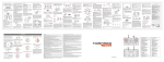
3)
Pulse Timer Process Time Change and Contact On/Off
If input condition turns on, output contact (Q) turns on.
The process time is newly changed when the timer function block is executed. When the process time
reaches the setting time (process time = setting time), the contact (Q) turns off.
The contact turns off after the setting time regardless of input condition off status.
The following diagram shows pulse timer timing.
IN
t0
t1
t2
t3
t5
t4
Q
t0
t0+PT
t2
t2+PT
t4
t2+PT
PT
ET
t0
4)
t1
t2
t4
Timer error
The maximum timer error is
‘1 scan time + time from the start of scan to execution of the timer function block".
4-9
t5
Chapter 4. CPU module
4.3.6 Counter Processing
The CPU module counter increment/decrement the present counting value by the detection of rising
edge(offÆon) of input signal. Three types of counter are increment counter, Decrement counter and
Increment-Decrement Counter. For details, refer to ‘GLOFA – GM Programming’.
• The Increment counter is a counter which increment the present counting value
• The Decrement counter is a counter which decrement the present counting value
• The Increment-Decrement counter is a counter which compares the counting values of two input conditions.
1)
Counter Present Value Change and Contact On/Off
(1) Increment Counter
• It should have Input condition (CU), reset condition (R) and setting value (PV).
PV
• If the counting value (CV) increments and reaches the setting value(PV) the output contact (Q) turns
on.
When the reset signal is turned on, the counting value is set to ‘0’ and the output contact (Q) turns
off.
(2) Decrement Counter
• It should have input condition (CU), load (LD) and setting value (PV).
CD
• If the counting value (CV) decrements and reaches ‘0’, the output contact (Q) turns on.
If the reset signal is turned on, the counting value is set to the setting value and the output contact
(Q) turns off.
4 - 10
Chapter 4. CPU module
(3) Increment/Decrement Counter
• It should have Increment input condition (CU), Decrement input condition (CD), load (LD) and
setting value (PV).
NAME
CTUD
BOOL ▶CU
QU
BOOL
BOOL ▶CD
QD
BOOL
BOOL
R
BOOL
LD
INT
PV
CV
INT
• If reset signal(R) turns on, counting value (CV) is set to ‘0’.
• If load signal(LD) turns on, counting value is set to setting value(PV).
• It is increased by 1at the rising edge of increment input(CU) and decreased by 1 at the edge of
decrement input(CD). If counting value(CV) is equal or larger than setting value(PV),QU will be on,
and if counting value(CV) is equal or less than setting value(PV),QD will be on.
2)
Counting speed
• The counting speed is decided by scan time and it will be counted when on time or off time of input
condition is larger than each scan time.
Max. Counting speed (Cmax.) = n / 100 × 1 / ts [pps]
[ n : Duty(%), ts : scan time(s) ]
• Duty is percent of on time / off time.
On
Off
Off
T1
T2
T1 ≤ T2 : n = T1 / (T1+T2) × 100 [%]
T1 > T2 : n = T2 / (T1+T2) × 100 [%]
4 - 11
Chapter 4. CPU module
4.4 Program
4.4.1 Program Configuration
A program consists of all of the function elements that is needed to execute a particular control. It is to be
stored in the internal RAM of the CPU module or the flash memory of the memory module.
The function elements are classified as below.
Function Elements
Processing Operation
Initialization
program
• Executed when the power is applied or the CPU operation is transited to the
RUN mode.
• Executes the initial/fixes data setting for execution of scan program and the
initialization of peripheral devices on special modules.
• The execution method of initialization differs according to the setting of
Restart Mode, etc.
Scan program
• Processes the constantly repeated signals which are executed every scan.
Time driven task program
• When the following time conditional processings are required the program is
executed complying with the time interval setting.
4In case that the processing need a shorter interval than that of average
one scan processing time.
4In case that the processing need a longer interval than that of average
one scan processing time.
4In case that the processing should be executed by the specified time
interval.
Event driven task program
• A shorter processing is executed for internal or external interrupt.
Error task program
• Error task program is executed, when error is occurred, if the user has made
error task program.(GM4-CPUC only)
4 - 12
Chapter 4. CPU module
4.4.2 Program Execution Procedure
The followings explain the program execution procedure when the power is applied or the CPU module key
switch is in the RUN status.
Program operation processing is executed as the procedure given below
Operation start
• Executed when the power has been applied
or the CPU operation is in the Run mode
Initialization program
• Restart operation is executed complying with
the initialization task(_INIT, HINIT)
*1
External task program
Scan program
Time driven task program
Executed only when the condition
has been satisfied.
Executed only when the condition
Internal task program
END processing
has been satisfied.
Error task program
Error task (_ERR_SYS)
(GM4-CPUC only)
Executed only when the condition
has been satisfied.
1)
HINT
*1 : In the GLOFA PLC, the time driven task programs and event driven task programs are called task
program.
Event driven programs are classified into single task(internal interrupt) or interrupt task (external
interrupt) according to the S/W and H/W interrupt signaling method.
4 - 13
Chapter 4. CPU module
1) Initialization program
(1) Function
• The Initialization program initializes the program to execute scan and task programs.
• The initialization can be executed with the restart mode which has been specified for program.
(2) Restart mode execution conditions
• The initialization tasks can be specified as below complying with the purpose of the initialization task.
4 Program for Cold/ Worm restart started by the _INIT task
4 Program for Hot Restart : started by the _H_INIT task
(3) Cold/ Warm Restart program
• The initialization program specified to _INIT task is executed with cold or warm restart mode when the
operation starts.
• This initialization program executes the operations repeatedly until the setting conditions are
satisfied(that is, until the Flag_INIT_DONE in the initialization program turns on). However, the I/O
refresh is still executed.
(4) Hot restart mode program
• Task programs specified to the _H_INIT task executes initialization with the hot restart mode when
momentary power failure has been occurred.
• This initialization program executes the operations repeatedly until the setting conditions are
satisfied(that is, until the flag _INIT_DONE in the initialization program turns on). In this case, I/O
refresh will not be executed. Therefore, the operation is executed with the data that has been stored
into the input image area before a momentary power failure had occurred.
2) Scan program
(1) Function
• In order to process signals which repeats constantly, the program executes its sequential operation
repeatedly from the first step to the end step.
• If the interrupt task execution condition has been satisfied by a time driven task or event driven task
module during scan program execution, the program that is under execution will be temporary stopped
and the corresponding task program will be executed.
• If the scan program has been completely executed, the single task(internal interrupt) execution condition
will be checked and the corresponding task program will be executed.
4 - 14
Chapter 4. CPU module
(2) configuration
• Up to 180 scan programs can be used.
(If task programs are used, the usable number is reduced as many as that of the used task programs)
• Program has been not specified to initialization or task program when writing that program, it will be
automatically specified to scan program.
• Scan program has lowest execution priority and the priorities of scan program are determined their
registration sequence in the GMWIN screen when writing those programs.
3) Task program
(1) Function
• In order to process internal/ external signal which occurs periodically or non-periodically, the task program
temporarily stop the operation of scan program and processes first the corresponding function
(2) Types
• Task programs are classified into the three types as below
4 Time driven task program : Up to 32 programs are applicable
4 Single (internal) task program : Up to 16 programs are applicable
4 Interrupt (external) task program : Up to 8 programs are applicable
• Time driven task program
4 The program is executed by the time internal set before
• Single (internal) task program
4 The corresponding program will be executed if the rising edge of the internal contact occurs.
4 The detection of the rising edge will be executed after the scan program has been processed.
• Interrupt (external) task program
4 The program is executed according to the external signal a input to the interrupt module
HINT
1) Refer to section 4.4.3 task for details of task program
4) Error Task program
• The program which is executed when system error is occurred during the operation of user’s program.
• User make error task program, and then program is executed on condition of ‘_ERR_SYS’ task. User can
protect system operation failure according as the user controls system error mask flag in the error task
program. (For details, refer to section 4.4.4 Error Handling)
4 - 15
Chapter 4. CPU module
4.4.3 Task
The followings explain the program structure and tasks of the GMWIN, that is, the GLOFA-GM programming
S/W, in order to give an understanding of the task function
Program 1
Task 1
Program Block
( program 1)
Program 2
Function
Program 3
Program Block
Program 4
Task 2
Function Block
*1
( program 3)
Program 5
Program Block
Task 3
Program 6
( program 7)
Function
Program 1
Program Block
HINT
1) A task executes the some function as the control panel
which are used to execute programs. Each task consists
of one or more program blocks in the three types of
program. Those programs are called task programs A
program to which a task has not been specified as
marked with '*1' will be automatically specified to scan
program
4 - 16
Chapter 4. CPU module
1) Task types and functions
The following table show the types and functions of tasks
Type
Time driven task
External interrupt task
Internal interrupt task
Number
8 (GM4-CPUA/B)
32 (GM4-CPUC)
8
16
Start up condition
Time driven interrupt
(up to 4,294,967.29s by the
10ms)
Rising or falling edge of
interrupt module input
contact
Detection and
execution
Executed periodically as
setting time
Detection delay
time
Up to 5ms delay
Specifications
Execution priority
Task Number
Immediately executed
when an edge occurs in
the interrupt module
Maximum 5ms delay +
Interrupt module delay
(within 0.5ms)
Level 0 to 7
(Level 0 has highest priority)
0 to 31 (User set it up not to
overlap)
The rising edge of the
BOOL variable data which
has been specified of
buffer data
Executed with edge
detection after scan
program has been finished
Delayed for the same time
as maximum scan time
Level 0 to 7
Level 0 to 7
32 to 39 (User set it up not
to overlap)
48 to 63 (User set it up not
to overlap)
2) Task program processing Method
The following explains the common processing method and instructions for task programs
(1) Task program characteristics
• The task program will be executed when a execution condition is satisfied while the scan program is
repeatedly processed at every scan. Be sure to consider that point when writing a task program
• For example, if a timer and a counter have been used in a 10 sec cycle time driven task program, the
timer can occur up to 10 sec error and an input which has been changed within 10 sec will not be counted
because the counter checks its input status every 10 sec
(2) Execution priority
• The higher priority task program will be first executed if several tasks are ready for their execution If same
priority tasks are ready, the FIFO will be applied.
• If a newly invoked task has higher priority than that of existing tasks which are under execution, they are
temporary stopped and task has higher priority will be executed.
• When determining the priority of a task program, consider the characteristics, importance and urgency of
the program
(3) Processing delay time
The following factors influence on the processing delay of task program, consider the characteristics,
importance and urgency of the program
• Task detection delay (Refer to the detailed description of each task)
• Execution delay due to the execution of prior task programs
• Delay due to the execution of higher priority task programs while executing task programs
4 - 17
Chapter 4. CPU module
(4) Relationship of task program to initialization or scan program
• User defined tasks will not start while the initialization task program is being executed. In case of hot
restart, the ready tasks before the power failure will be executed after the power has been restored.
• As scan program has the lowest priority, if a task is invoked the scan program will be stopped and the
task programs will be processed prior to them. Therefore, if tasks are invoked many times or
concentrated sometimes the scan time may be extended abnormally. Be cautious when setting task
conditions.
(5) Protection of the programs under execution from task programs
• If problems can be occur in case that program lose its execution continuousness by the task programs
which have higher proprieties, the execution of task programs can be partly perverted For program
protection, use the DI function(Task program start-up disable) or EI function(task program start-up
enable)
3) Time driven task program processing method
The followings explain the processing method of a task program when its task condition(start-up condition) has
been set to be driven by time.
(1) Settings that have to be set for the task
• Set the task execution cycle and its priority which are used as start-up conditions for the task programs to
be executed. Check the task NO. for task control
(2) Time driven task processing
• The corresponding time driven interrupt task program will be executed every setting time internal
(execution cycle).
(3) Precautions for using the time driven task program
• While a time driven task program is being executed or ready for its execution, if a same priority task
program has been invoked to be executed the newly invoked task will be ignored, the representative task
collision warning flag (_TASK_ERR) will be set to ON, the detailed system error flag(_TC_BMAP[n] will be
set to ON at its corresponding location and occurrence time of the time driven tasks whose execution
requests have been ignored will be written at its corresponding location of the flag _TC_CNT[n].
• The timer that invokes the execution request for time driven task programs will be incremented only when
the operation mode is in the RUN mode
If the RUN mode has been changed into the PAUSE mode while operating with the RUN mode, and then
the operation mode has been changed again into the RUN mode, the operation time spent with the
PAUSE mode and the power failure time of Hot restart will all be ignored.
• When setting the execution cycle for a time driven task program, be cautious that execution requests for
many time driven task programs can occur. If four time driven task programs of cycle 2, 4, 10 and 20sec
are used, four execution requests will occur every 20 sec and scan time can be momentarily extended.
4 - 18
Chapter 4. CPU module
4) External contact program processing method
The following explains in the case that the task( start-up condition) of a task program has been set to an
external interrupt contact signal.
(1) Settings that have to be set for the interrupt module
• Set the dip switch to rising edge or falling edge at each contact of the interrupt module complying with
the requested conditions.
(2) Settings that have to be set in the task
• Set the contact No. of interrupt module and priority module in the task that will be used as start-up
conditions of the task programs to be executed. Check the task No. for task control.
(3) External contact task processing
• If an interrupt occurs in the interrupt module by a signal which is applied from the external, the CPU
module recognize this signal and executes the task program which are invoked by the contact at which
the signal has been occurred.
(4) Precautions for using an external contact task.
• While a task program which are invoked by an interrupt module contact is being executed or ready for its
execution, if an execution request of a task program has been occurred to the same input contact then
the newly invoked task will be ignored, the representative task collision warning flag(_TASK_ERR) will be
set to ON, the detailed system error flag(_TC_BAMP[n]) will be set to ON at its corresponding location
and the occurrence time of the external task whose execution request has been congested.
• Execution request for a task program can be accepted only when the operation mode is in the RUN
mode. That is, if the RUN mode has been changed into the PAUSE mode while operating with the RUN
mode and the operation mode has been changed into the RUN mode again, all execution requests
occurred during the operation with the PAUSE mode will be ignored.
5) Internal task program processing method
The following explains the processing method when the task (start-up condition) of a task program has been
set to the contact of direct variable area(I, Q or M) or automatic variable area.
(1) Settings that have to be set for the task.
• Set the contact and priority that will be the startup conditions of the task program that will be executed.
Check the task No. for task control .
(2) Internal contact task processing
• After the execution of scan program has been completed in the CPU module, the contacts that are the
start-up conditions of the task program will be checked and the internal task programs where rising edge
has been occurred will be executed with its priority. Task program will be executed only once when rising
edge is detected.
(3) Precautions when using an internal task program.
• The internal task program is executed when scan program has finished its execution. Therefore, though
the execution condition for the internal task program has been invoked in the scan program or task
program(time driven, external) the task (start-up condition) will not be immediately executed but will be
executed when scan program has finished its execution.
4 - 19
Chapter 4. CPU module
• If execution of an internal task program is requested, the execution conditions will be checked when scan
program has finished its execution. Therefore, if an internal task execution conditions, during ‘one’ scan,
has been occurred and disappeared (if the specified contact has been turned from OFF to ON, and then
from ON to OFF) by scan program or (time driven or external) task program the task will not be executed
as the execution condition can not be detected at the time that execution conditions are being checked.
6) Task processing at momentary power failure
• If the momentary power failure time has been longer than the allowable hot restart setting time and the
system restarts with cold restart or warm restart mode, the ready tasks and the tasks invoked during the
power failure will all be ignored and only the tasks from the start time will be processed.
• In case of the power failure of 20 ms or less, the ready tasks before the power failure will be executed, a
time driven task will be invoked with calculation of the power failure time, and time driven tasks invoked
repeatedly before the power failure will be ignored.
7) Examination on task program
After writing down a task program, be sure to examine the following items.
(1) Task setting has been correctly done?
If tasks are invoked more frequently than necessary or several tasks are invoked simultaneously within one
scan, the scan time become longer and irregular. In case that the task setting cannot be changed, check
the maximum scan time.
(2) Task priorities are properly arranged?
The lower priority tasks still may not be processed after its time due to delay by higher priority tasks. In
some cases, if the prior tasks have been delayed and next task occurs task collision can occur. Set the
priority with due consideration of items such as urgency and execution time of a task.
(3) Task programs are written as shortly as possible?
If execution time of a task program is long, the scan time may become longer and irregular and also
collision of task programs may occur. Therefore, write task programs as shortly as possible.
(4) Protection of lower priority programs against higher priority program isn’t needed during execution of those
programs.
If the priority of a task program (or a scan program) has been set to lower priority and other tasks must not
interrupt during its execution, use the function ‘DI’ and ‘EI’ to protect the program partly. When processing
global variables used commonly in other programs, special modules or communications modules, problems
can occur.
HINT
1) For examination on processing speed of scan program and task program, refer to the ‘Scan time
Calculation Example in the Section 4.2.3 ‘Scan Time’.
4 - 20
Chapter 4. CPU module
8) Example of program configuration and processing
When the task and program have been registered as below,
• Task registration : T_SLOW (interval : T#10ms, priority : = 0)
PROC_1 (single : %MX0, priority : = 3)
E_INT1 (interrupt : 0, priority : = 0)
• program registration : program → P0
program → P1 with the task T_SLOW
program → P2 with the task PROC_1
program → P3 with the task E_INT1
If program execution time is equal to external interrupt occurrence time :
• Execution time for each program : P0 = 17 ms, P1 = 2 ms, P2 = 7 ms, P3 = 2 ms
• Interrupt E_INT occurrence time : Occurred at the 6, 7, 20 ms after the operation started.
• PROC_1 : Invoked during execution of scan program
Program execution is shown as below.
• Processing with time [ms]
0 [ms] : Scan starts and the scan program P0 starts its execution.
0 to 6 [ms] : The program P0 is being executed.
6 to 8 [ms] : Execution request for P3 is input, and P0 is stopped and P3 is executed. Execution request for
P1 by E_INT1 at the 7 [msec] is ignored as the P2 is being executed.
8 to 10 [ms] : P3 finishes its execution and the P0 stopped continues its execution.
10 to 12 [ms] : P0 is stopped and P1 is executed due to execution request for P1.
12 to 20 [ms] : P2 finishes its execution and the P0 stopped continues its execution.
20 [ms] : Execution requests for P1 and P3 are simultaneously exist, but the higher priority P1 is executed
and P3 is ready for its execution.
20 to 22 [ms] : P0 is stopped and P1 is executed.
22 to 24 [ms] : P1 finishes its execution and the higher priority P3 is executed before P0.
24 to 25 [ms] : P3 finishes its execution and the P0 stopped completes its execution.
25 [ms] : Execution request for P2 is checked at the finish time of the scan program (P0) and P2 is executed.
25 to 30 [ms] : The program P2 is executed.
30 to 32 [ms] : Execution request for P1 is input and P2 is stopped and P1 finishes its execution.
32 to 34 [ms] : P1 finishes its execution and the P2 stopped finishes its execution.
34 [ms] : A new scan starts. (P0 starts its execution.)
4 - 21
Chapter 4. CPU module
4.4.4 Error Handling
1) Error Classification
Errors occur due to various causes such as PLC system defect, system configuration fault or abnormal
operation result. Errors are classified into fatal error mode, which stops system operation for system
stability, and ordinary error mode, which continues system operation with informing the user of its error
warning.
The main factors that occurs the PLC system error are given as followings.
• PLC hardware defect
• System configuration error
•Operation error during execution of the user programs
• External device malfunction
2) Operation mode at error occurrence
In case of error occurrence, the PLC system write the error contents the corresponding flags and stops or
continues its operation complying with its operation mode.
(1) PLC hardware defect
The system enters into the STOP state if a fatal error such as the CPU module defect has occurred,
and continues its operation if an ordinary error such as battery error has occurred.
(2) System configuration error
This error occurs when the PLC hardware configuration differs from the configuration defined in the
software. The system enter into the STOP state.
(3) Operation error during execution of the user programs
If the numeric operation error of these errors occurs during execution of the user programs, its
contents are marked on the error flags and the system continues its operation. If operation time
overruns the watch dog time or I/O modules loaded are not normally controlled, the system enters into
the STOP state.
(4) External device malfunction
The PLC user program detects malfunctions of external devices. If a fatal error is detected the system
enters into the STOP state, and if an ordinary error is detected the system continues its operation.
HINT
1) In occurrence of a fatal error the state is to be stored in the representative system error flags,
and an ordinary error in the representative system warning flags.
2) For details of flags, refer to Appendix 2. Flag List.
4 - 22
Chapter 4. CPU module
4.4.5 Precautions when using special modules
This system offers convenience and high performance in using special modules compared with the existing
methods. Therefore, take some precautions when composing the system. Check the system after the
following items have been thoroughly understood.
1) Special module programming
(1) Special function block is offered for each special module to make programs concise and to prevent
errors in writing down the user program.
(2) Function blocks are largely of two types. ‘Initialization’ function block for initializing special modules and
‘control’ function block for control of the operations of special modules. Function block functions as an
interface between the user program data and the special modules. As it includes the function that
watches the operation status of special modules and indicates the error status, other separate error
diagnosis program does not have to be written.
(For detailed description of function block, refer to the User’s Manuals of special modules and GLOFAGM instructions.)
2) Special Module Initialization
This means to define the operations of a special module. It is done with ‘initialization’ function block.
Generally, it specifies the data range to used channel, resolution or filtering method, etc. It defines the
hardware characteristics and only one time execution at system start is sufficient.
HINT
1) As the initialization should be finished before the scan program starts its execution, its program
should be written in the restart program (initialization task program). If the hot restart is used, the
same initialization program should also be written in the hot restart initialization program.
3) Control of special modules
In control the operations of special modules, write the program using function blocks which correspond to
the operations that have to be controlled. These function blocks can locate at any place within the
program.
HINT
1) If a power failure occurs in the base unit where special units are loaded, special modules data are
removed. Therefore, data should be newly written down in the program.
2) If hot restart is used the data in the other parts of the system continues. However, output modules
such as the ‘D/A conversion module’ output standard output of the STOP mode before new data are
to be written in the program. If data are written to the special modules every scan normal output is
immediately output, but standard output maintains if the output data are changed or written
periodically. In this case, in order to maintain continuity of output, it is recommended that an output
data restore program be written in the hot restart program.
4 - 23
Chapter 4. CPU module
4) Control of special module on the remote base unit
• In order to the operations of special modules on the remote base unit, use remote function blocks
offered for control of each module in programming. Initialization and control of the module are similar
with those of special modules on the extension base unit.
• As, in remote base unit, mounting or dismounting is possible during its operation, initialization and data
restore programs are requested, which should have the condition flags of the remote base unit as its
start-up conditions.
5) Restart Program Example
(1) System Configuration
The followings give an example for writing the initialization program of the system where a special
module has been loaded onto its basic base unit shown as below figure.
The followings describe an example for writing the ‘cold/warm restart program’, ‘hot restart program’
and ‘scan program’ for the scan program where the ‘D/A 02’ outputs data every scan and the ‘D/A 03’
outputs data only when the data has been changed.
R Y 32
D C 32
D / A (2)
D / A (1)
A / D (1)
C P U
P O W E R
A/D : A/D conversion module
D/A : D/A conversion module
DC32 : 32-point DC input module
RY32 : 32-point relay output module
• As cold/warm restart makes the whole system restart, the ‘cold/warm restart program’ consists of
only initialization program of special module.
• Initialization of special modules by the hot restart program’ is needed before the scan program which
has been stopped at the hot restart will continue its execution. It is possible that the output conditions
of the module ‘D/A 03’, which outputs data only when the data has been changed, are restored to the
state before the stop of the program.
4 - 24
Chapter 4. CPU module
(2) program
• Project Configuration : Restart.prj
4 - 25
Chapter 4. CPU module
• Program : cw_rst.src (cold/warm restart initialization program)
STAT
STAT
4 - 26
Chapter 4. CPU module
• Program : hot_rst.src (hot restart initialization program)
STAT
STAT
4 - 27
STAT
Chapter 4. CPU module
• Program : scan.src (scan program)
4 - 28
Chapter 4. CPU module
4.5 Operation Modes
The CPU module operates in one of the four modes - the RUN, STOP, PAUSE and DEBUG mode.
The following describes the PLC operation processing in each operation mode.
4.5.1 RUN mode
In this mode, programs are normally operated.
The first scan start in the RUN mode
If the operation mode is the RUN mode
when the power is applied
Mode condition at the start
If the operation mode has been changed
from the STOP mode to the RUN mode
Data area initialization complying with the restart mode
Data area initialization complying with the restart
mode set
Check on the effectiveness of the program and decision
on the possibility of the execution
Execution of input refresh
Execution of programs and task programs
Check on the normal operation of the loaded modules
and their mounting conditions
Processing the communications service or other
internal operations
Execution of output refresh
The RUN mode is maintained
Is the operation mode changed?
Changed into another mode
Operation with the operation mode changed
1) Processing when the operation mode changes.
Initialization of data area is executed when the first scan starts.
(1) If the PLC is in the RUN mode when applying the power :
(2) If the operation mode has been changed into from the STOP mode into the RUN mode : the
initialization is executed complying with the restart mode set. (cold / warm / hot)
(3) The possibility of execution of the program is decided with check on its effectiveness.
2) Operation processing contents
I/O refresh and program operation are executed.
(1) Task programs are executed with the detection of their start-up conditions.
(2) Normal or abnormal operation and mounting conditions of the loaded module are checked.
(3) Communications service or other internal operations are processed.
4 - 29
Chapter 4. CPU module
4.5.2 STOP mode
In this mode, programs are not operated. Program sending through the GMWIN is available only in the
remote STOP mode.
1) Processing when the operation mode changes
The output image area is cleared and output refresh is executed.
2) Operation processing contents
(1) I/O refresh is executed.
(2) Normal or abnormal operation and mounting conditions of the loaded module are checked.
(3) Communications service or other internal operations are processed.
4.5.3 PAUSE mode
In this mode, the program operation is temporarily stopped. If it returns to the RUN mode, the operation
continues from the state before the stop.
1) Processing when the operation mode changes
Data area clear and input image clear are not executed and the operating conditions just before the mode
change is maintains.
2) Operation processing contents
(1) I/O refresh is executed.
(2) Normal or abnormal operation and mounting conditions of the loaded module are checked.
(3) Communications service or other internal operations are processed.
4.5.4 DEBUG mode
In this mode, errors of a program are searched and the operation sequence is traced. Changing into this
mode is only possible in the STOP mode. In this mode, a program can be checked with examination on its
execution state and contents of each data.
1) Processing when the operation mode changes
(1) Data area is initialized at the starting time of the mode change complying with the restart mode, which
has been set on the parameters.
(2) The output image area is cleared and output refresh is executed.
2) Operation processing contents
(1) I/O refresh is executed.
(2) Debug operation is executed complying with the setting status.
(3) Output refresh is executed after the debug operation has been executed to the end of a program.
(4) Normal or abnormal operation and mounting conditions of the loaded module are checked.
(5) Communications service or other internal operations are processed.
4 - 30
Chapter 4. CPU module
3) Debug operation conditions
• Two or more of the following four operation conditions can be simultaneously specified.
Operation conditions
Executed by the one
operation unit, (step over)
Executed to the specified
breakpoint.
Executed according to
the contact state
Executed by the specified
scan number.
Description
If an operation command is ordered, the system operates one operation unit
and stops.
• If breakpoints are specified in the program the operation stops at those
breakpoints.
• Up to 32 breakpoints can be specified.
If the contact area to be watched and the condition (Read, Write, Value)
where the operation has to stop are specified, the operation stops when
the specified operation occurs at the specified contact.
If the number of scan that will be operated is specified, the operation stops
after it has operated by the specified scan number.
4) Operation method
(1) Execute the operation after the debug operation conditions have been set in the GMWIN.
(2) In task programs, each task can be specified to operation enable/disable.(For detailed operation
method, refer to the GMWIN User’s Manual Chapter 9.
4.5.5 Operation mode change
1) Operation mode change methods
The following method are used to change the operation mode.
(1) Change by the CPU module mode keys.
(2) Change by the GMWIN connected with the CPU module communications port.
(3) Change by the GMWIN connected to the remote CPU module through Fnet.
(4) Change by the user’s command using FAM or computer link module, etc.
(5) Change by the ‘STOP function’ during program execution.
2) Operation mode change by the CPU module mode keys
The following shows the operation mode change by the CPU module mode keys.
Mode key position
RUN
STOP
STOP → PAU/REM
PAU/REM → RUN *1
RUN → PAU/REM
PAU/REM → STOP
Operation mode
Local RUN
Local STOP
Remote STOP
Local RUN
Local PAUSE
Local STOP
HINT
1) *1 : If the operation mode changes from RUN mode to local RUN mode by the mode key, the PLC
operates continuously without stop.
4 - 31
Chapter 4. CPU module
3) Remote operation mode change
Remote operation mode change is available only when the operation mode is set to the remote STOP
mode (i.e., the mode key position is in the ‘STOP →PAU/REM’).
Mode key
position
PAU/REM
Mode Change
Remote STOP → Remote RUN
Remote STOP → Remote PAUSE
Remote STOP → DEBUG
Remote RUN → Remote PAUSE
Remote RUN → Remote STOP
Remote RUN → DEBUG
Remote PAUSE → Remote RUN
Remote PAUSE → Remote STOP
Remote PAUSE → Remote DEBUG
DEBUG → Remote STOP
DEBUG → Remote RUN
DEBUG → Remote PAUSE
Mode change by
the GMWIN
○
×
○
○
○
×
○
○
×
○
×
×
Mode change using FAM
or computer link, etc.
○
×
○
○
○
×
○
○
×
○
×
×
4) Remote operation mode change enable/disable
It is possible to disable the mode change for system protection so that some parts of the operation mode
sources cannot change the mode. If remote operation mode change has been disabled, the operation
mode change is possible only by the mode key and GMWIN. To enable the remote operation change, set
the parameter ‘Enabling the PLC control by communications’ to enable.
(For details, refer to the Appendix 1. System Definitions)
4.5.6 System Starting Method
1) Starting Method
The follows show the methods to start PLC systems stably. In order to improve system reliability, observe
the starting rules.
(1) Starting by local key :
Download the program in the stop mode, and then set key switch to ‘RUN’.
(2) Starting by GMWIN :
Set key switch to ‘PAU/REM’, and then select ‘RUN’ in the GMWIN ‘Online’ menu.
(3) Starting by turning on power :
Set key switch to ‘RUN’, and then turn on power. On the other hand, if key switch was ‘Remote RUN’
mode just before turning off PLC, and it is ‘PAU/REM’ mode right now, it is available to start when to
turn on power.
(4) Restarting by reset key :
There are two kinds of reset, ‘Reset’ and ‘Overall reset’.
4 - 32
Chapter 4. CPU module
• Reset : It is operated by pushing reset switch in front of CPU module. It is same operation with turning
on power (off Æ on)
• Overall reset : It is operated by pushing reset switch in front of CPU module over 5 seconds.
2) Starting method by system setting
(1) Normal starting
• When turning on power, CPU module checks system configurations. If it is late to turn on power of
expansion bases, it waits turning on power of them.
In the ‘STOP’ mode, after 10 seconds waiting, error is occurred.
• After editing program, the first starting is cold restart.
• When restarting the system which was stopped by normal method, it restarts according to set-up
parameter. There are key switch, GMWIN, turning off power, and reset in the starting methods.
• If it was stopped by error on running, restart method is decided according to kinds of error and
release method.
(2) When I/O module skip function is set up
• In case of I/O module, which is set up I/O module skip function, it is excluded in operation on running,
and error diagnosis function is not executed. If skip function is released on running, the I/O module is
included to normal operation. For details, refer to ‘4.6.10 I/O module skip function’ and ‘4.6.11
module changing function on operation’.
(3) When error mask function is set up
• The module, which is set up error mask, is included on operation and executed error diagnosis
function. However, when system starts, if module type disagreement error is occurred, operation is
continued. For details, refer to ‘4.6.9 error mask function’
4 - 33
Chapter 4. CPU module
4.6 Functions
4.6.1 Restart mode
The restart mode defines how to initialize variables and the system and how to operate in the RUN mode
when the system starts its operation with the RUN mode by re-application of the power or mode change.
Three restart modes, cold, warm and hot restart are available and the execution condition for each restart
mode is given below.
(For details, refer to the ‘4.5.1 Basic Parameters Edit’ of the GMWIN User’s Manual Section 4.5 Parameters
Edit.
1) Cold Restart
(1) It is executed when the restart mode parameter has been set to the cold restart mode.
(2) All data are cleared with ‘0’ and only the variables to which their initial value has been defined will be
set to their initial value.
(3) Though the parameter has been set to the warm restart mode, cold restart will be executed at the first
execution of a program after it has been changed.
(4) Pressing the manual reset switch(the reset command in the GMWIN performs same function) makes
the system operate with the cold restart mode regardless of the restart mode set by the parameter.
2) Warm Restart
(1) It is executed when the restart mode parameter has been set to the warm restart mode.
(2) If a data is specified so that it can retain its previous value, the value remains during the warm restart.
If a data has been set to an initial value, the value will be set during the warm restart. All other data will
be cleared with ‘0’.
(3) Though the parameter has been set to the warm restart mode, cold restart will be executed at the first
execution of a program after it has been stopped due to its down load and error.
(4) Though the parameter has been set to the warm restart mode, cold restart will be executed if data
contents are abnormal (i.e., the data does not remain at a power failure)
3) Hot Restart
(1) If the operation mode is in the RUN mode when the power is re-applied after a power failure and the
time from power failure to re-application of the power falls into within the allowable hot restart time, the
operation starts with the hot restart mode. .
(2) All data and program execution elements will be restored to their state before the power failure. As the
program is executed from the state just before the power failure, continuity of the program is
maintained even at the momentary power failure
(3) If the allowable hot restart time has been overrun, the restart mode which has been set by the
parameter will be executed.
(4) Cold restart will be executed if data contents are abnormal (i.e., the data does not remain at a power
failure)
HINT
1) Consider the followings when setting the allowable hat restart time.
(1) The system executes the hot restart initialization program if the time from a power failure to
completion of system check after the restore is less than the setting time.
(2) If a power failure occurs again before the hot restart initialization program completes its
execution, the hot restart program executes again. If a power failure of 20 ms or more has
occurred, about 0.5 sec delay can occur until the system operates normally after it has been
restored form the power failure. The allowable hot restart time is set by the second.
4 - 34
Chapter 4. CPU module
• Restart mode is executed as the figure given below when the power has been re-applied during execution of the
CPU module
Power applied
STOP
Operation mode
Operation in the STOP mode
RUN
Data that remains at
power failure
Hot restart time
Abnormal
Over the time
Cold Restart
Within the time
Restart mode
Warm Restart
Hot Restart executed
Warm Restart executed
Cold Restart executed
Operation in the RUN mode
4) Data initialization according to the restart mode
The variables relating to the restart mode are classified into three types, i.e, default variable, initialization
variable and retain variable. The following table shows the initialization method for each type variable.
Mode
Cold
Warm
Hot
Variable type
Default
Initialized with ‘0’
Initialized with ‘0’
Previous value is retained
Retain
Initialized with ‘0’
Previous value is retained Previous value is retained
Initialization
Initialized with the user Initialized with the user Previous value is retained
defined value
defined value
Retain & Initialization
Initialized with the user Previous value is retained Previous value is retained
defined value
HINT
1) Definitions
(1)Default variable : A variable whose initial value is not defined or previous value will not be retained.
(2)Initialization variable : A variable whose initial value is defined.
(3)Retain variable : A variable whose previous value will be retained.
4 - 35
Chapter 4. CPU module
4.6.2 Self-diagnosis
1) Functions
(1) The self-diagnosis function permits the CPU module to detect its own errors.
(2) Self-diagnosis is carried out when the PLC power supply is turned on and when an error occurs the
PLC is in the RUN state. If an error is detected, the system stops operation to prevent faulty PLC
operation.
2) Error flag
If an error occurs, it will be stored to the following flags and the STOP LED flickers.
• Representative system error flag : _CNT_ER
• Representative system warning flag : _CNF_WAR
HINT
1) Refer to 12.5 Error Code List of Chapter 12. Troubleshooting for details of contents of self-diagnosis
and corrective actions.
4.6.3 Clock function
A clock device(RTC) is basically included in the CPU module. The RTC continues its operation by the backup
battery when the power turns off or at the 20msec or more momentary power failure.
The clock data of the RTC can be used for time control of system or of error history. The system operation
status information flag is updated with the RTC present time every scan.
1) Clock Data
Item
Year
Month
Day
Hour
Minute
Second
1/100 sec
Day of the week
Data
2 digit (solar calendar)
1 to 12
1 to 31
0 to 23 (the twenty-four-hour system)
0 to 59
0 to 59
0 to 99
0 to 6 (Monday to Sunday)
2) Timer error
±5 sec per month
3) Clock data Read/Write
Clock data can be read from/written to the PLC information in the GMWIN on-line mode.
(For details, refer to the GMWIN User’s Guide Section 7.10 PLC information)
HINT
1) The RTC, at first, has no written clock data.
When using the CPU module, be sure to set exactly the RTC with a clock data.
2) Battery error can cause the RTC to stop or error in it.
In this case, writing a new clock data to the RTC removes the error.
3) If a RTC error occurs, the flag _RTC_ERR of the system warning flag _CNF_WAR turns on.
If the RTC is restored to normal state, the flag _RTC_ERR turns off.
4 - 36
Chapter 4. CPU module
4.6.4 Remote function
The CPU module can be controlled by external operations (from GMWIN and computer link module, etc. For
remote operation, set the SPU module mode setting key to remote position.
1) Remote RUN/STOP
(1) The remote RUN/STOP permits external operations to RUN/STOP the CPU module under the condition
that the CPU module key switch is in the remote position.
(2) This function is convenient when the CPU module is located on the place where it is difficult to control the
CPU module or the user want to control the CPU module in the control panel from outside.
2) Remote PAUSE
(1) The remote PAUSE permits external operations to execute PAUSE operations under the condition that the
CPU module key switch is in the remote position. The PAUSE operations stop the CPU module operation
processing while maintaining the On/Off state of the output module.
(2) This function is convenient when the user wants to maintain the ON state of the output module under the
condition the CPU module has been stopped.
3) Remote DEBUG
(1) This function permits external operations to execute DEBUG operations under the condition that the CPU
module key switch is in the remote position. The DEBUG operations execute programs complying with the
specified operation conditions.
(2) This function is convenient when program execution or contents of any data are checked for debugging of
the program.
4) Remote reset
(1) This function permits remote operations to reset the CPU module, which locates in the place where direct
operations cannot be applied, when an error has occurred.
HINT
1) For remote function operations, refer to the GMWIN User’s Manual Chapter 7. On-line.
4 - 37
Chapter 4. CPU module
4.6.5 I/O Force On/Off function
1) Force On/Off setting method
Force on/off setting is applied to input area and output area.
Force on/off should be set for each input and output, the setting operates from the time that ‘Force I/O
setting enable’ is set.
This setting can be done when I/O modules are not really loaded.
2) Force on/off Processing timing and method
(1) Force Input
• After data have been read from input modules, at the time of input refresh the data of the junctions
which have been set to force on/off will be replaced with force setting data to change the input image
area. And then, the user program will be executed with real input data and force setting data.
(2) Force output
• When a user program has finished its execution the output image area has the operation results. At
the time of output refresh the data of the junctions which have been set to force on/off will be replaced
with force setting data and the replaced data will be output. However, the force on/off setting does not
change the output image area data while it changes the input image area data.
(3) Force on/off processing area
• Input/output areas for force on/off setting are larger than the real I/O areas. If remote I/O is specified
using this area, the force on/off function is as just available in it as in the basic I/O areas.
(4) Precautions
• Turning the power off and on, changed of the operation mode or operations by reset key does not
change the previous force on/off setting data. They remain within the CPU module and operation is
executed with the same data.
• Force I/O data will not be cleared even in the STOP mode.
• If a program is downloaded or its backup breaks, the force on/off setting data will be cleared. The
operating program in memory differs from the program in the flash memory so that if operation restarts
with the program in the flash memory the on/off setting data will be also cleared.
• When setting new data, disable every I/O settings using the setting data ‘clear’ function and set the
new data.
HINT
1) For detailed operation, refer to the GMWIN User’s Manual Chapter 7 ‘Force I/O setting’
4 - 38
Chapter 4. CPU module
4.6.6 Direct I/O Operation function
This function is usefully available when an input junction state is directly read during execution of a
program and used in the operation, or the operation result is directly output to an output junction.
1) Direct input
• Direct input is executed by use of the ‘DIRECT_IN’ function. If this function is used, the input image
area will be directly updated and applied to the continuing operations.
2) Direct output
• Direct output is executed by use of the ‘DIRECT_O’ function. If this function is used, the data of the
output image area, which has the operation results by the time, will be directly output to the direct output
module.
3) Force on/off
• Force on/off settings are still effective when processing direct I/O.
HINT
1) For detailed direct I/O functions, refer to the GLOFA-GM commands.
4.6.7 History Log-In
History Log-In is classified into three types, i.e., error history, mode change history and power off history.
Up to latest 16 histories are stored.
1) Error recording time and content
(1) Error history
• Recording time : When an error has occurred during operation.
• Stored content : Occurrence time and error code
(2) Mode change history
• Recording time : When an operation mode change has occurred
• Stored content :Occurrence time, operation mode and restart mode
(3) Power off history
• Recording time : When a power off has been occurred during operation in the RUN mode.
• Stored content : Occurrence time(16), Occurrence count(1)
2) Stored History Data Reset
The stored history data will not be cleared until it is cleared by menu selection in the GMWIN.
HINT
1) For detailed instructions, refer to the ‘PLC information’ in the GMWIN User’s Manual Chapter 7 On-line.
4 - 39
Chapter 4. CPU module
4.6.8 External Device Error Diagnosis function
Flags are given for the user to implement easily the program in which the error detection of external
devices and system stop and warning are coded. By use of these flags, error indication of external devices
is possible without complex programming and monitoring of the error location can be done without special
tools (GMWIN, etc.) or source programs.
1) External device fault detection and classification
(1) The user program detects external device faults. The faults are classified into fatal fault( error), where
the PLC stops its operation, and ordinary fault(warning), where operation continues.
(2) The flag ANC_ERR[n] is used to indicate error. The flag ANC_WN[n] is used to indicate warning.
2) External Device Fatal-fault (Error) Processing.
(1) If an error of external device is detected and the error type, where other value than 0 is used, is written
to the system flag ANC_ERR[n], the flag will checked at the time that scan program finishes its
execution. If an error is indicated on the flag, it will be also indicated on the _ANNUN_ER of the
representative system error flag _CNF_ER, the PLC turns all output modules off and the error state
will be same as the PLC self-diagnosis.
(2) The user can know the cause of error by use of the GMWIN, and also by direct monitoring of the flag
_ANC_ERR[n].
(3) As the flag _ANC_ERR[n] has sixteen elements(n : 0 to 15), the user can classify error states largely.
User defined error No. can be written to the elements. A number of 1 to 65535 is usable.
Example)
Error detection
MOV
10
_ANC_ERR [0]
3) External device Ordinary-fault (Warning) Processing.
(1) If a warning of external device is detected and the corresponding flag of the system flag _ANC_WB[n]
is set to on, the flag will checked from the _ANC_WB[0] at the time that scan program finishes its
execution. If an error is indicated on the flag, it will be also indicated on the _ANNUN_WR of the
representative system warning flag _CNF_WAR. External device waning numbers will be written to
from _ANC_WAR[0] to _ANC_WAR[7] according to occurrence sequence.
(2) The user can know the cause of error by use of the GMWIN, and also by direct monitoring of the flags
_ANC_WAR[n] and _ANC_WB[n].
(3) If an external device waning is removed, that is, the elements of _ANC_WAR[n] are released from
warning, the corresponding _ANC_WAR[n] will be automatically cleared. If all element flags are
cleared, the flag _ANNUN_WR of the system flag _CNF_WAR will be reset.
4 - 40
Chapter 4. CPU module
Example
Error detection
ANCWB[10]
(
)
_ANNUN_WR
_ANC _WAR[0]
_ANC _WAR[1]
_ANC _WAR[2]
_ANC _WAR[3]
_ANC _WAR[4]
_ANC _WAR[5]
_ANC _WAR[6]
_ANC _WAR[7]
=
=
=
=
=
=
=
=
=
1
10
0
0
0
0
0
0
0
If the user program had detected a system fault and set
_ANC_WB[10] to ON, the states of _ANNUN_WR
and
_ANN_WAR [0..7] will be shown as left after the scan has been
finished
_ANNUN_WR
_ANC _WAR[0]
_ANC _WAR[1]
_ANC _WAR[2]
_ANC _WAR[3]
_ANC _WAR[4]
_ANC _WAR[5]
_ANC _WAR[6]
_ANC _WAR[7]
=
=
=
=
=
=
=
=
=
1
10
0
0
0
0
0
0
0
After the next scan has been finished, if the numbers 1, 2, 3, 10, 15 ,
40 , 50, 60 and 75 of _ANC_WB[n] are tuned on _ANC_WAR[n] will be
shown as left
_ANNUN_WR
_ANC _WAR[0]
_ANC _WAR[1]
_ANC _WAR[2]
_ANC _WAR[3]
_ANC _WAR[4]
_ANC _WAR[5]
_ANC _WAR[6]
_ANC _WAR[7]
=
=
=
=
=
=
=
=
=
1
10
0
0
0
0
0
0
0
_ANNUN_WR
_ANC _WAR[0]
_ANC _WAR[1]
_ANC _WAR[2]
_ANC _WAR[3]
_ANC _WAR[4]
_ANC _WAR[5]
_ANC _WAR[6]
_ANC _WAR[7]
=
=
=
=
=
=
=
=
=
1
10
0
0
0
0
0
0
0
As the number 10 has turned on (has occurred) in the previous scan,
though the number 10 has lower priority than the numbers 1, 2 and 3, it
will be the lower element of _ANC_WAR[n]. The _ANC_WB[75] is not
indicated as it is turned on and the warning that occurred before has
written to the _ANC_WAR[n].
After the next scan has been finished, if the numbers 1, 2, 3, 10, 15 ,
40 , 50, 60 and 75 of _ANC_WB[n] are tuned on _ANC_WAR[n] will be
shown as left.
The No. 10 warning has been released the content of _ANC_WAR[0] will
be cleared and the contents of _ANC_WAR[1..7] will shift into the lower
elements. The content of _ANC_WAR[7] will has been cleared by the
shifting and the content of _ANC_WB[75] will be written to _ANC_WAR[7].
If all warnings indicated on the _ANC_WB[n] are released during
operation, the _ANNUN_WR and _ANC_WAR[n] will be shown as left.
4 - 41
Chapter 4. CPU module
4.7 GM4-CPUC Dedicated Functions
4.7.1 Error Mask Function
1) Uses and operation introductions
Error mask function is the function which makes program to be continued and ignores the error even if
the specific module makes error on operation. The module, which is assigned to error mask, renews the
I/O data normally and executes error diagnosis until the error is occurred. If the module makes error on
operation, CPU module indicates the error to flag or GMWIN and continues operating. (blinking RUN
LED : 40ms)
2) Error mask setting up
• Error mask function can be set up module error and user generated error.
(For details, refer to ‘Appendix 2. Flag List’.)
• Error mask function can be set up by GMWIN and user programs.
• Error mask function can be set up in advance or set up by the error task program.
HINT
1) Even if the cause of error is removed, if error flag of CPU module is not initialized and then error mask
is released, system is shut down. Before error mask flag is released, check error flag.
2) Even if there are power on/off, changing operation mode and handling reset key, error mask data is
operated because the state is maintained in the CPU. Therefore, in case of revision of error mask
function, use GMWIN or user programs.
3) In case of the follow, error mask data is erased.
(1) In case of re-operating after downloading program by GMWIN.
(2) In case of memory backup is broken up because battery is dead.
4 - 42
Chapter 4. CPU module
4.7.2 I/O Module Skip Function
1) Uses and operation introductions
I/O module skip function is the function which excludes the specific module in the operation. I/O data
revision and error diagnosis are not executed in the specific module. It can be useful for temporary
operation where erroneous part is excluded.
2) Configurations and I/O data processing
• It can be set up about each of I/O modules (For details, refer to GMWIN User’s Manual)
• Because input refreshing is stopped, input image area maintains the previous values when I/O module
skip function is set up. However, also in this case, I/O image area handling by force On/Off function is
available.
• Real outputs of output modules are set to ‘Off’ when setting I/O module skip function, but output image
area is variable by operation of user program. After skip function is set, outputs of output modules can
not be altered by force On/Off.
• When using direct I/O operation function, the operation of I/O skip function is same.
HINT
1) Even if there are turning on/off power, changing operation mode and handling reset key, the previously
set I/O skip data operates as it did because the state in the CPU module is maintained. Cancellation of
I/O skip function is available by GMWIN or user program.
2) I/O skip data can be erased in follow cases.
(1) In case of re-operating after downloading program by GMWIN..
(2) In case of memory backup is broken up because battery is dead.
4 - 43
Chapter 4. CPU module
4.7.3 Online Module Changing Function
Online module changing function is available in the GM4C system. However, because online module changing can
be the reason of the system error, extra attentions are required. Be sure to follow the steps of the User’s manual.
1)
Precautions for use
• The modules in the main base can not be changed.
• Base, power and communication module can not be changed.
• When changing module, be sure to insert the module correctly.
• All of I/O modules can be changed and the follow special modules can be changed.
4 G4F-AD2A, G4F-AD3A, G4F-DA1A, G4F-TC2A, G4F-RD2A
4 G4F-DA2V, G4F-DA2I, G4F-DA3V, G4F-DA3I, G4F-AD3A
2)
Module changing method
The method of changing module is as follow.
(1) Using GMWIN, set I/O skip function about the slot of the base where the changing module is mounted.
(2) Using GMWIN, set error mask function about the slot of the base where the changing module is mounted.
(3) Change the module.
(4) In case of special module, Initialize by GMWIN.
(5) Using GMWIN, release the slot from I/O skip function.
(6) After checking the normal operation (and also the error flag), release error mask function.
HINT
1) In case of using I/O skip function in order to change module, cut off the loaded power, and in case of
using I/O force On/Off function, deliberate to set input image.
2) In order to prevent the overall system error caused by changing module or module error when handling
module change, be sure to set error mask function as above steps.
Warning
1)
In case of mounting module, if the module is mounted incorrectly, it can cause malfunctions of the
other modules. Be sure to that above hook of module is inserted to above joint of base entirely.
4 - 44
Chapter 4. CPU module
3)
Initialization of special module
Special module is necessary to initialize again in case of being reset special module on CPU operation
because special modules have initialization function of channel specification by S/W.
(1) Initialization of special module by GMWIN
• In case of changing special module as the above module changing method ‘(4)’, select ‘Initialize
special module’ in the Online menu of GMWIN, and then initialize as follow method.
(G4F-DA2V, G4F-DA2I, G4F-DA3V and G4F-DA3I are not necessary to initialize.)
4 Assign slots of the special module to initialize.
4 Assign the value which is the same with initial value of initial function block in the program.
4)
Changing remote base
Remote base can be attached and detached on operation, so when changing module, extra handling is not
necessary because there is initialization program of special module on operation program.
4 - 45
Chapter 4. CPU module
4.7.4 I/O Reservation Function
1)
Uses and operation introductions
I/O Reservation Function is the function which can be used in order to add other I/O modules without
stopping systems when adding the I/O modules later on.
• I/O Reservation Function can be applied to digital I/O module and D/A conversion module.
2)
Operation
The method of I/O Reservation Function is as follow.
(1) Using GMWIN, check ‘Use Reserved I/O Function’ in the GMWIN basic parameter.
(2) Download the basic parameter to PLC.
(3) Using GMWIN, set I/O parameter about the modules which will be added later on.
(4) Download the I/O parameter to PLC.
(5) Using GMWIN, set I/O module skip function and error mask function about the specific I/O slots which
the additional modules will be mounted in later on.
(6) Execute H/W Reset (by PLC Reset Switch) or S/W Reset (by GMWIN), or turn on the PLC
(7) Start operation.
In case of mounting the additional module :
(8) Mount the additional module to the I/O slot, which was set in the step (3), without stopping system.
(9) In case of mounting D/A conversion module, execute ‘Initialize Special Module’ about the module.
(10) Release I/O module skip function in the slot of the additional module.
(11) Confirm the normal operation of ‘I/O module writing/reading’, ‘module loading/unloading error flag’ and
other relative flags. (For more details, refer to App 2-7 ‘Detailed System Error and Warning Flag List’.)
(12) Release error mask function in the slot of the additional module.
HINT
The I/O Reservation Function can be applied in the following environment.
(1) GM4-CPUC O/S version : Version 2.1 or over.
(2) GMWIN version : Version 4.03 or over.
(3) GM4 high performance main base (GM4-BxMH) and high performance expansion base (GM4-BxEH)
Warning
In case of mounting module using I/O reservation function, be sure to follow the above steps of the operation,
in order to prevent malfunction of the whole PLC system.
4 - 46
Chapter 4. CPU module
4.7.5 FEnet Reset Function
1) Uses and operation introductions
FEnet Reset Function is the function which clears FEnet module only without reset of the whole system,
when the communication of the FEnet does not work correctly by the certain trouble.
2) Operation
In order to reset FEnet only, set the appropriate flag of the following flag list by using variable monitor on
GMWIN or using coil in the scan program. When the reset operation is ended, the flag is cleared to ‘0’
again.
• FENET_RESETx : To use for reset FEnet of the slot No. x.
(1) _FENET_RESET_Mx : Main base
(2) _FENET_RESET_Ex : Expansion base
• RCV_SERx_CHy : To display setting slot No. x and channel No. y by using dedicated service.
(1)
_RCV_SERVx_M_CH : Main base
(2)
_RCV_SERVx_E_CH : Expansion base
• RCV_SERx_COUNT : Receiving count of slot No. x by using dedicated service.
(1)
_RCV_SERV_CNT_M : Main base
(2)
_RCV_SERV_CNT_E : Expansion base
• x (Slot) : 0 ~ 55 (GM4-CPUC), y (Channel) : 0 ~ 15
HINT
The FEnet Reset Function can be applied in the following environment.
(1) GM4-CPUC O/S version : Version 2.1 or over.
(2) GMWIN version : Version 4.04 or over.
(3) Fast Enet O/S version : Version 1.1 or over.
Warning
1) After the FEnet reset operation is finished, it takes minimum 5 to 6 more seconds to stabilize the
system. After the FEnet reset operation, make sure NOT to retry the FEnet reset function immediately.
If the FEnet reset function is retried immediately without waiting minimum 5 to 6 seconds when the
previous FEnet reset operation is ended, it can cause the whole system reset.
2) In case of using the scan program in order to set the FEnet reset flag, be sure to use ‘Positive
transition-sensing contact (---| P |---)’ for the executing condition of the coil. If the FEnet reset function
is retried, be sure to use set the FEnet reset flag after minimum 5 to 6 seconds from the end of the
previous FEnet reset operation. Do NOT retry the FEnet reset operation immediately without waiting 5
to 6 seconds when the previous FEnet reset operation is ended.
3) The FEnet reset function should be executed within the limit of the emergency, and also it is need to be
executed very cautiously. For more details, refer to ‘FEnet User’s Manual’.
4 - 47
Chapter 4. CPU module
4.8 Memory Configuration
The CPU module includes two types of memory that are available by the user. One is program memory which is used
to store the user programs written to implement a system by the user. The other is data memory which stores data
during operation.
1) Program memory configuration
The table given below shows the contents to be stored and the storage capacity of program memory.
Item
Overall program memory area
System area :
• System program area
• Backup area
Parameter area
• Basic parameter area
• I/O parameter area
• High speed link parameter area
• Interrupt setting information area
Program area
• Scan program area
• Task program area
• User defined function/function block area
• Standard library area
• Access variable are
• Variable initialization information area
• Protective variable specification information area
GM4-CPUA/B
GM4-CPUC
129K byte
1M byte
1.5K byte
13K byte
3.5K byte
10K byte
123K byte
977K byte
2) Data memory Configuration
The table given below shows the contents to be stored and the storage capacity of program memory.
Item
Overall data memory area
System area
• I/O information table
• Force I/O table
System flag area
Input image area (%IX)
Output image area (%QX)
Direct variable area (%M)
Symbolic variable area (maximum)
Stack area
GM4-CPUA
64K byte
GM4-CPUB
64K byte
GM4-CPUC
512K byte
7.5K byte
6.5K byte
50K byte
1.5K byte
512 byte
512 byte
2 to 16K byte
52K byte – the size of
direct variable area
4K byte
4 - 48
1.5K byte
4,096 byte
1K byte
4,096 byte
1K byte
4,096 byte
2 to 16K byte
8 to 64K byte
50K byte – the size of 428K byte – the size
direct variable area of direct variable area
4K byte
4K byte
Chapter 4. CPU module
3) Purpose
(1) System area
Used to store the self-created data of the CPU module for system management and GMWIN system control
data.
(2) System flag area
Used to user flags and system flags. The user operates it with flag name.
(3) Input image area
Used to store input data read from input modules. Overall size is %IX0.0.0 to %IX63.7.63, however, the
area %IX.0.0.0 to %IX3.7.63 is really used for input module area.
The area that is not used by the real input module loaded is a free area that the program can use. Especially, it
will be convenient to use that free area for storing remote input data through high speed link.
(4) Output image area
Used to store operation results. The stored data are automatically output to output modules. Overall size
is %QX0.0.0 to %QX63.7.63, however, the area %QX.0.0.0 to %QX3.7.63 is really used for output module
area in the GM3/4 series.
The area that is not used by the real output module loaded is a free area that the program can use. Especially,
it will be convenient to use that free area for storing remote output data through high speed link.
(5) Direct variable area
The user can use this area to access direct memory data through the variable names such
as %MX0, %MB0, %MW0, %MD0 and %ML0, which was pre-defined by the system.
(6) Symbolic variable area
Used to store the variables that the user created, that is, whose names the user defined when writing a
program. Global variables and instance memory are located in this area. The variables used in program
blocks locates in the ‘PB instance memory’ of the program, and the memory used in function block locates in
the ‘FB instance memory’.
The maximum size of the PB instance memory is 32K byte. If the used size overruns the maximum size, divide
the program blocks or use global variables.
4 - 49
Chapter 4. CPU module
4.9 I/O No. Allocation Method
1) I/O No. allocation means to give an address to each module in order to read data from input modules and output
data to output modules.
2) Fixed 64 points are allocated to each module for I/O points.
3) Fixed 64 points are allocated regardless of mounting/dismounting or type of modules.
4) The following shows I/O No. allocation method.
Input : % I X 0. 0. 0
Output :% Q X 0. 1. 15
I/O Module junction No.
0 to 63
Slot No.
0 to 7
Base No.
0 to 3
(GM4C : 0 to 6)
HINT
The main base having 12 I/O slots is recognized as base no. 1.
I/O
Base no.
I/O
I/O
I/O
I/O
I/O
I/O
I/O
I/O
I/O
I/O
I/O
CPU
Power
Slot no.
0 1 2 3 4 5 6 7 8 9 10 11
0
1
4 - 50
Chapter 5. BATTERY
Chapter 5.
BATTERY
5.1 Specifications
Item
Normal voltage
3.0 VDC
Specifications
Warranty life time
3 years
Application
Programs and data backup, and RTC runs in power failure
Specifications
Lithium Battery, 3 V
External dimension (mm)
Φ14.5 × 26
5.2 Precautions for use
1) Do not heat or solder its terminals.
2) Do not measure its voltage with a tester or short circuit.
3) Do not disassemble.
5.3 Battery Replacement
Backup battery needs periodic replacement. Programs and power failure retain data remains for about 30
minutes by the super capacitor though the battery is removed at a power failure, but the battery has to be
replaced as soon as possible.
The following shows the battery replacement procedure.
Battery replacement
Open the cover of the CPU module.
Release the existing battery from the holder and disconnect the connector.
Insert a new battery into the holder in the exact direction and connect the
connector.
No
Stop LED flickering?
Yes
Complete
Battery error
5-1
Chapter 6. Memory Module And Built-in Flash Memory
Chapter. 6
Memory Module And Built-in Flash Memory
This chapter describes user programs storage method and operation method of the PLC mounted with the
memory module. Flash memory is being used for the memory module in this PLC.
Operation methods are different according to types of CPU module.
6.1 GM4-CPUA (Using Memory Module)
6.1.1 Memory module
Items
Models
G4M-M032
Memory type
Flash memory
Memory capacity
128K bytes ( 32K steps )
Weight (Kg)
0.01
6-1
Chapter 6. Memory Module And Built-in Flash Memory
6.1.2 Method of writing a user program to the memory module
Be sure to turn the power off when mounting the memory module onto the CPU module. It means to store the
user program in the program memory of the CPU module to the memory module. That is only available when
the operation mode is the STOP mode.
• The following shows the method of writing a user program to the memory module,
Start
Power On
Change the operation mode to the STOP mode and turn the power off.
Mounting the memory module
Mount correctly the memory module onto the connector for memory module in the CPU module.
Turn the power on.
Check the memory module information
Use the GMWIN to check the memory module just mounted.
Execution
Select the Flash Memory Write in the GMWIN
(This instruction makes the contents of the program memory of the PLC written to the memory module. A
program to be stored into the memory module has to exist in the program memory. )
Complete
HINT
1) For detailed handling instructions, refer to the chapter 7 “Flash Memory” of the GMWIN User’s Manual.
6-2
Chapter 6. Memory Module And Built-in Flash Memory
6.1.3 Operation method
• Be sure to turn the power off when mounting the memory module onto the CPU module.
• If the operation mode is the RUN mode when the power is turned on or the operation mode changes from
other mode into the RUN mode after the power has turned on, a user program in the memory module starts
its operation after it has been written to the program memory of the CPU module.
Start
Power-Off
Change the operation mode into the STOP mode and then turn the power off
Mounting the memory module
Load correctly a memory module where a user program has been written onto the connector for memory
module in the CPU module as described above.
Power-On
(If a memory module where no program has been written is mounted onto the CPU module, ‘Write to
memory module’ will be executed.)
Changing the operation mode
Change the operation mode into the RUN mode.
Execution Check
Check if the changed program is executed or not.
Check the information of the memory module by using GMWIN.
Complete
HINT
1) If the operation mode was the RUN mode when the power has been turned on then mounting a memory
module makes the contents in the memory module will be written to the program area of the CPU module.
Be cautious when mounting a memory module to write a user program to the memory module.
It will be convenient to operate the PLC without memory module during debugging and to mount a memory
module after the debugging.
6-3
Chapter 6. Memory Module And Built-in Flash Memory
6.2 GM4-CPUB (Using Built-in Flash Memory)
6.2.1 Operation mode setting
GM4-CPUB does not use separate memory module in order to operate the ROM operation function of GM4-CPUA.
Using Built-in flash memory of GM4-CPUB instead of memory module, it can execute the function which stores user
program or corresponds to ROM operation function of GM4-CPUA.
GM4-CPUB executes ROM operation function by using dip switch for flash memory operation
Dip Switch for Flash Memory Operation
Flash Memory
6.2.2 Storing program in the built-in flash memory and operation method
1)
Change operation mode of GM4-CPUB module to STOP mode.
2)
There are two methods to write program in the GM4-CPUB.
(1) In general, when writing program to the GM4-CPUB, GMWIN shows the below message.
◆ In case of storing downloading program to flash memory, click Yes(Y).
HINT
◆ The above message is displayed in case of selecting Online – Write – Parameter and program in the
GMWIN menu.
6-4
Chapter 6. Memory Module And Built-in Flash Memory
(2) The follow shows the method to store in the flash memory without overwriting program.
◆ The below message is displayed in case of selecting Online – Flash memory(F) – Write(W) in the
GMWIN menu.
◆ Select the item which should be stored to flash memory, and then click OK.
(3) In case of restarting PLC system, operate as follow according to dip switch for flash memory operation.
Selection of DIP switch
Operation
ON
CPU is operated by the program in flash memory when power on or PLC
reset.
ON
CPU recognizes that no program is in flash memory and is operated by
program which is stored in program memory.
( Caution : Lower switch should be at the off position. )
HINT
State of dip switch for flash memory is not concerned with storing program.
In case of storing program in the flash memory, set GM4-CPUB to STOP mode.
In case of trying to store in the RUN mode, the follow message is displayed.
6-5
Chapter 6. Memory Module And Built-in Flash Memory
6.3 GM4-CPUC (Using Built-in Flash Memory)
GM4-CPUC does not use separate memory module in order to operate ROM operation function of GM4-CPUA.
Using Built-in flash memory of GM4-CPUC instead of memory module, it can execute the function which stores user
program or corresponds to ROM operation function of GM4-CPUA.
Moreover, GM4-CPUC has built-in flash memory of large capacity. Upload program is stored in the storing area for
upload program in the flash memory. In short, the follow shows flash memory structure.
1M
PRAM
FLASH
Program
Program
1M
Upload
5M
6.3.1 Program storing method by using built-in flash memory
1) Flash operation mode setting
GM4-CPUC executes ROM operation function by using flash operation mode setting in the GMWIN menu.
Using ‘Online – Flash memory – Set Mode’, check Flash Run Mode Setting, and then click OK.
◆ In case of selecting ‘None Set Run Mode’, flash operation does not work.
◆ Initial setting is ‘Set Run Mode’.
6-6
Chapter 6. Memory Module And Built-in Flash Memory
HINT
◆ What is Flash operation mode? It means that PLC is operated by backup program in the flash memory in
case of that data in the program RAM get damaged. In case of selecting ‘Flash Memory operation’, when
PLC restarts or operation mode is changed to RUN, data are copied to program memory in the CPU
module and then operation is started.
◆ After setting once in the GMWIN, flash operation mode is maintained if it is not set to Off by GMWIN.
◆ GM4-CPUC is available to write to flash memory in the RUN mode.
◆ On program debugging, operate in the state of flash operation mode is set to Off. After completion of
debugging, if flash operation mode is set up, it is convenient to write flash memory.
2) Program storing method in the built-in flash memory
There are three methods to store program in the built-in flash memory.
2.1) When downloading program.
When flash operation mode is set, if program is written to GM4-CPUC, the following message is displayed
in the GMWIN.
◆ In case of storing downloaded program to the flash memory, click Yes(Y).
HINT
◆ If not click Yes(Y), flash operation mode is released, and the program in the flash memory is erased.
2.2) In case of changing flash operation mode from ‘None Set Run Mode’ to ‘Set Run Mode’
Flash function is activated, and program in the program memory is stored to flash memory
6-7
Chapter 6. Memory Module And Built-in Flash Memory
HINT
In case of changing flash operation mode from ‘Set Run Mode’ to ‘None Set Run Mode’
Flash function is inactivated, and program in the flash memory is erased.
2.3) In case of online editing
GM4-CPUC supports writing flash memory during online editing. If ‘write’ in online editing is clicked after online
editing in case of setting flash operation mode, the follow message is displayed.
◆ ‘Write Now’ / ‘Write during Disconnecting’. Choose one of them.
HINT
◆ In case of using online editing very often, if ‘Write during Disconnecting’ is selected, the program is copied
to flash memory in case of ‘disconnecting / changing operation mode’ only.
◆ In case of writing program to flash memory during online editing, flash service is executed for 1/8 of the
scan time in order NOT to have an effect on executing time of scan program. Therefore the execution
requires much time, and it is variable according to the scan program.
◆ In case of online editing in the remote mode, it can cause losing data. Therefore, Use online editing in the
local connecting as possible.
6-8
Chapter 6. Memory Module And Built-in Flash Memory
6.3.2 Setting operation mode
In case of re-operating PLC systems or changing operation mode to Run mode, it operates like the follows
according to flash operating mode setting.
Flash operating mode setting
Operation
ON
The program, which is stored in the flash memory, operates after
downloading it to program memory.
(In case of that programs in the flash memory and program memory are
equal, downloading operation is not executed.)
OFF
CPU recognizes that there is not a program in the flash memory, and it is
operated by the program, which is stored in the program memory.
6.3.3 Upload program storing method by using built-in flash memory
Basically, the upload program is stored to the flash memory in the GM4-CPUC, and there are 4 kinds of methods
to store upload program to the flash memory. When to write upload program, flash operation mode setting has no
effect on it.
1) In case of choosing ‘Upload Program’ together when to download program
2) In case of choosing ‘Upload Program’ together when to download parameter and program
6-9
Chapter 6. Memory Module And Built-in Flash Memory
3) In case of choosing ‘Upload Program’ when PLC is running
If ‘Online’ Æ ‘Write’ menu is chosen when PLC is running, ‘Upload Program’ menu is activated. Using this menu,
the upload program can be written separately. This function is supplied for the user who does not need to write
upload program in the stop mode, but need to write the upload program without stopping PLC when it is running.
4) In case of online editing when an upload program has been already written.
◆ ‘Write Now’ / ‘Write during Disconnecting’. Choose one of them.
HINT
◆ In case of using online editing very often, if ‘Write during Disconnecting’ is selected, the upload program is
copied to flash memory in case of ‘disconnecting’ only.
◆ In case of writing the upload program during running, the operation time is variable according to the scan
time.
6 - 10
Chapter 7. INPUT AND OUTPUT MODULES
Chapter. 7 INPUT AND OUTPUT MODULES
7.1 Notes on Selecting Input and Output Modules
The followings describe instructions for selection of digital I/O modules that will be used in the GLOFA-GM4
series.
1) The types of digital input are current sink input and current source input.
When selecting DC input modules consider the specifications of those input devices as the wiring method of
the external input power supply varies complying with the type of digital input.
In the GM4 series, the types are dedicated source input and source/sink common DC input.
(1) The method to connect sink type external connection device to Source type DC input module
-
External
Connection
Device
I
DC
Input
DC POWER
Module
+
COM
• The external connection device is located between negative(-) terminal of DC input module and DC power.
• In case of turning on input, current flows to external connection device from DC input module terminal.
(2) The method to connect sink type external connection device to Source type DC input module
+
External
Connection
Device
I
DC
Input
DC POWER
Module
-
COM
• The external connection device is located between positive(+) terminal of DC input module and DC power.
• In case of turning on input, current flows to DC input module terminal from external connection device.
2) The number of maximum simultaneous input points differs with the type of a module. Check the specifications
of the input module to be applied before use.
3) Use the interrupt module if high speed input response is requested.
But, only one interrupt module can be mounted in each CPU module.
4) Use transistor output modules or triac output modules with a load that is frequently opened and closed or with
an inductive load as, in those cases, the life span of a relay output module will become shorter than specified.
7- 1
Chapter 7. INPUT AND OUTPUT MODULES
7.2 Digital Input Module Specifications
7.2.1 16-points 12/24 VDC input module (source/sink type)
Model
Specifications
Number of input points
Insulation method
Rated input voltage
Rated input current
Operating voltage range
Maximum simultaneous input points
ON voltage/ON current
OFF voltage/OFF current
Input impedance
Response time
OFF → ON
ON → OFF
Common terminal
Internal current consumption
Operating indicator
External connections
Weight
GM4
G4I-D22A
16 points
Photo coupler
12/24 VDC
5/11 mA
10.2 to 26.4 VDC (ripple: less than 5%)
100% simultaneously ON
9.5 VDC or higher/4.0 mA or higher
6 VDC or lower/1.0 mA or lower
Approx. 2.2 kΩ
10 msec or less
10 msec or less
8 points/common(COM)
70 mA
LED turns on at ON state of input
20-points terminal block connector(M3 × 6 screws)
0.25 kg
7- 2
Chapter 7. INPUT AND OUTPUT MODULES
7.2.2 16-points 12/24 VDC input module (source type)
GM4
G4I-D22B
Models
Specifications
Number of input points
16 points
Insulation method
Photo coupler
Rated input voltage
12 VDC
24 VDC
Rated input current
5 mA
11 mA
Operating voltage range
10.2 to 26.4 VDC (ripple: less than 5%)
Maximum simultaneous input points
100% (8 points/COM) simultaneously ON
ON voltage/ON current
9.5 VDC or higher/4.0 mA or higher
OFF voltage/OFF current
6 VDC or lower/1.0 mA or lower
Input impedance
Approx. 2.2 kΩ
Response time
OFF → ON
10 msec or less
ON → OFF
10 msec or less
Common terminal
8 points/COM
Internal current consumption
70 mA
Operating indicator
LED turns on at ON state of input
External connections
20-point terminal block connector(M3 × 6 screws)
Weight
0.25 kg
7- 3
Chapter 7. INPUT AND OUTPUT MODULES
7.2.3 32-points 12/24 VDC input module (source/sink type)
GM4
Model
Specifications
G4I-D24A
Number of input points
Insulation method
Rated input voltage
Rated input current
Operating voltage range
Maximum simultaneous input points
ON voltage/ON current
32 points
Photo coupler
12/24 VDC
3/7 mA
10.2 to 26.4 VDC (ripple: less than 5%)
60% simultaneously ON (19 points/COM)
9.5 VDC or higher/3.0 mA or higher
OFF voltage/OFF current
6 VDC or lower/1.5 mA or lower
Input impedance
OFF → ON
Approx. 3.3 kΩ
10 msec or less
ON → OFF
10 msec or less
Response time
Common terminal
32 points/common
Internal current consumption
Operating indicator
External connections
Weight
75 mA
16-points indication by selection switch.
37-pin D-Sub connector
0.19 kg
7- 4
Chapter 7. INPUT AND OUTPUT MODULES
7.2.4 32-points 12/24 VDC input module (source type)
Specifications
GM4
G4I-D24B
Model
Number of input points
Insulation method
Rated input voltage
Rated input current
Operating voltage range
Maximum simultaneous input points
ON voltage/ON current
OFF voltage/OFF current
Input impedance
OFF → ON
Response time
ON → OFF
Common terminal
Internal current consumption
Operating indicator
External connections
Weight
32 points
Photo coupler
12 VDC
24 VDC
3 mA
7 mA
10.2 to 26.4 VDC (ripple: less than 5%)
60% (19 points/ 1 COM) simultaneously ON
9.5 VDC or higher/3.0 mA or higher
6 VDC or lower/1.5 mA or lower
Approx. 3.3 kΩ
10 msec or less
10 msec or less
32 points/1 COM(common)
70 mA
LED turns on at ON state of input
37-pin D-sub connector
0.19 kg
7- 5
Chapter 7. INPUT AND OUTPUT MODULES
7.2.5 16-points 24 VDC input module (source/sink type)
Specifications
GM4
G4I-D24C
Model
Number of input points
Insulation method
Rated input voltage
Rated input current
Operating voltage range
Maximum simultaneous input points
ON voltage/ON current
OFF voltage/OFF current
Input impedance
OFF → ON
Response time
ON → OFF
Common terminal
Internal current consumption
Operating indicator
External connections
Weight
16 points
Photo coupler
24 VDC
7 mA
20.4 to 28.8 VDC (ripple: less than 5%)
100% simultaneously ON
17 VDC or higher/5.2 mA or higher
8 VDC or lower/2.4 mA or lower
Approx. 3.3 kΩ
10 msec or less
10 msec or less
8 points/1 COM(common)
70 mA
LED turns on at ON state of input
20-point terminal block connector(M3 × 6 screws)
0.25 kg
7- 6
Chapter 7. INPUT AND OUTPUT MODULES
7.2.6 32-points 24 VDC input module (source/sink type)
Specifications
GM4
G4I-D24C
Model
Number of input points
Insulation method
Rated input voltage
Rated input current
Operating voltage range
Maximum simultaneous input points
ON voltage/ON current
OFF voltage/OFF current
Input impedance
OFF → ON
Response time
ON → OFF
Common terminal
Internal current consumption
Operating indicator
External connections
Weight
32 points
Photo coupler
24 VDC
7 mA
20.4 to 28.8 VDC (ripple: less than 5%)
60% (19 points/ 1 COM) simultaneously ON
17 VDC or higher/5.2 mA or higher
8 VDC or lower/2.4 mA or lower
Approx. 3.3 kΩ
10 msec or less
10 msec or less
32 points/1 COM(common)
75 mA
16-points indication by selection switch.
37-pin D-sub connector
0.19 kg
7- 7
Chapter 7. INPUT AND OUTPUT MODULES
7.2.7 64-points 12/24 VDC input module (source/sink type)
Model
Specifications
Number of input points
Insulation method
Rated input voltage
Rated input current
Operating voltage range
Maximum simultaneous input points
ON voltage/ON current
OFF voltage/OFF current
Input impedance
Response time
10 msec or less
10 msec or less
Common terminal
Internal current consumption
Operating indicator
External connections
Weight
GM4
G4I-D28A
64 points
Photo coupler insulation
12 / 24 VDC
3 / 7 mA
10.24 ~ 26.4 VDC ( ripple: 5% or less )
19 points / 1COM (60%)
9.5 VDC /3.0 mA
6 VDC / 1.5 mA
About 3.3kΩ
10 msec or less
10 msec or less
32 points / 1 com
250 mA
LED display
40-pin D-sub connector (2 connectors)
0.46 kg
7- 8
Chapter 7. INPUT AND OUTPUT MODULES
7.2.8 16-points 110 VAC input module
Specifications
G4I-A12A
Number of input points
Insulation method
Rated input voltage
Rated input current
Operating voltage range
Maximum simultaneous input points
Inrush current
ON voltage/ON current
OFF voltage/OFF current
Input impedance
Response time
GM4
Models
OFF → ON
ON → OFF
Common terminal
Internal current consumption
Operating indicator
External connections
Weight
16 points
Photo coupler
100 to 120 VAC (50/60 Hz)
11 mA (110 VAC / 60 Hz)
85 to 132 VAC (50/60 Hz ± 3 Hz)
100% simultaneously ON
600 mA, 0.12 msec or lower (264 VAC)
80 VAC or higher/6 mA or higher
30 VAC or lower/3 mA or lower
Approx. 10 kΩ
15 msec or less
25 msec or less
8 points/1 COM
70 mA
LED turns on at ON state of input
20-point terminal block connector(M3 × 6 screws)
0.29 kg
7- 9
Chapter 7. INPUT AND OUTPUT MODULES
7.2.9 16-points 220 VAC input module
Specifications
GM4
Model
Number of input points
Insulation method
Rated input voltage
Rated input current
Operating voltage range
Maximum simultaneous input points
Inrush current
ON voltage/ON current
OFF voltage/OFF current
Input impedance
OFF → ON
Response time
ON → OFF
Common terminal
Internal current consumption
Operating indicator
External connections
Weight
G4I-A22A
16 points
Photo coupler
200 to 240 VAC (50/60 Hz)
11 mA (220 VAC / 60 Hz)
170 to 264 VAC (50/60 Hz ± 3 Hz)
100% simultaneously ON (8 points / 1 COM)
600 mA, 0.12 msec or lower (264 VAC)
150 VAC or higher/4.5 mA or higher
50 VAC or lower/3 mA or lower
Approx. 10 kΩ
15 msec or less
25 msec or less
8 points/1 COM
70 mA
LED turns on at ON state of input
20-point terminal block connector(M3 × 6 screws)
0.3 kg
7- 10
Chapter 7. INPUT AND OUTPUT MODULES
7.2.10 Interrupt input module
GM4
Model
Specifications
G4F-INTA
Number of input points
Insulation method
Rated input voltage
Rated input current
Input impedance
Operating voltage range
Maximum simultaneous input points
ON voltage/ON current
8 points
Photo coupler
24 VDC
10 mA
Approx. 2.4 kΩ
21.6 to 26.4 VDC
100% simultaneously ON
15 VDC or higher/6.5 mA or higher
OFF voltage/OFF current
5 VDC or lower/2.0 mA or lower
Response time
Common terminal
OFF → ON
ON → OFF
0.5 msec or less
0.5 msec or less
1 point/ 1COM
Internal current consumption
Ascending or descending edge (Setting Dip switch by the channel)
Internal current consumption
65 mA
Operating indicator
LED turns on at ON state of input
External connections
20-point terminal block connector(M3 × 6 screws)
Weight
0.16 kg
7- 11
Chapter 7. INPUT AND OUTPUT MODULES
7.3 Digital Output Module Specifications
7.3.1 16-point relay output module
Number of output points
Insulation method
Rated load voltage/current
Minimum load voltage/current
Maximum load voltage/current
Off leakage current
Maximum switching frequency
Surge absorber
Mechanical
Service life
Electrical
Off → On
On → Off
Common terminal arrangement
Internal current consumption
External power Voltage
supply
Current
Operation indicator
External connections
Weight
Response time
GM4
Models
Specifications
G4Q-RY2A
16 points
Photo coupler
24 VDC 2A(load resistance)/1 point, 4 A/ 1 COM
220 VAC 2A(COSΨ = `1)
5 VDC / 1 mA
250 VAC, 125 VDC
0.1 mA (220 VAC, 60 Hz)
3600 times per hour
None
20 million times or more
Rated load voltage/current 100000 times or more
200 VAC 1,5 A, 240 VAC 1 A (COSΨ = 0.7) 100000 times or more
200 VAC 1 A, 240 VAC 0.5 A (COSΨ = 0.35) 100000 times or more
24 VAC 1,5 A, 100 VDC 0.1 A (L/R= 7 msec) 100000 times or more
10 msec or less
12 msec or less
8 points/common
100 mA (24 VDC all points ON)
24 VDC ± 10 % (ripple voltage : 4VP-P or less)
150 mA (24 VDC all points ON)
LED turns on at ON state of output
20-point terminal block connector (M3 × 6 screws)
0.31 kg
7- 12
Chapter 7. INPUT AND OUTPUT MODULES
7.3.2 16-point transistor output module (sink type)
Specifications
GM4
G4Q-TR2A
Models
Number of output points
Insulation method
Rated load voltage/current
Operating load voltage range
Maximum load current
Off leakage current
Maximum inrush current
Maximum voltage drop at ON circuit
Surge absorber
Off → On
Response
time
On → Off
Common terminal arrangement
Internal current consumption
Voltage
External
power supply Current
Operation indicator
External connections
Weight
16 points
Photo coupler
12/24 VDC
10.2 to 26.4 VDC
0.5 A / 1 point, 3 A / 1 COM
0.1 mA
4 A / 10 msec or less
1.5 VDC
Barrister
2 msec or less
2 msec or less
8 points/1 COM
110 mA (24 VDC all points ON)
24 VDC ± 10 % (ripple voltage : 4VP-P or less)
100 mA or less (24 VDC per COM)
LED turns on at ON state of output
20-point terminal block connector (M3 × 6 screws)
0.27 kg
7- 13
Chapter 7. INPUT AND OUTPUT MODULES
7.3.3 16-point transistor output module (source type)
Specifications
GM4
G4Q-TR2B
Models
Number of output points
Insulation method
Rated load voltage/current
Operating load voltage range
Maximum load current
Off leakage current
Maximum inrush current
Maximum voltage drop at ON circuit
Surge absorber
Off → On
Response
time
On → Off
Common terminal arrangement
Internal current consumption
Voltage
External
power supply Current
Operation indicator
External connections
Weight
16 points
Photo coupler
12/24 VDC
10.2 to 26.4 VDC
0.5 A / 1 point, 3 A / 1 COM
0.1 mA
4 A / 10 msec or less
1.5 VDC
Barrister
2 msec or less
2 msec or less
8 points/1 COM
110 mA (24 VDC all points ON)
24 VDC ± 10 % (ripple voltage : 4VP-P or less)
100 mA or less (24 VDC per COM)
LED turns on at ON state of output
20-point terminal block connector (M3 × 6 screws)
0.27 kg
7- 14
Chapter 7. INPUT AND OUTPUT MODULES
7.3.4 32-point transistor output module (sink type)
Specifications
GM4
Models
Number of output points
Insulation method
Rated load voltage/current
Operating load voltage range
Maximum load current
Off leakage current
Maximum inrush current
Maximum voltage drop at ON circuit
Surge absorber
Off → On
Response
time
On → Off
Common terminal arrangement
Internal current consumption
External
Voltage
power supply Current
Operation indicator
External connections
Weight
G4Q-TR4A
32 points
Photo coupler
12/24 VDC
10.2 to 26.4 VDC
0.1 A / 1 point, 2 A / 1 COM
0.1 mA or less
4 A / 10 msec or less
1.0 VDC
None
2 msec or less
2 msec or less
32 points/1 COM
160 mA (all points ON)
24 VDC ± 10 % (ripple voltage : 4VP-P or less)
100 mA or less (24 VDC per COM)
16-points indication by selection switch.
37-pin D Sub-connector
0.18 kg
7- 15
Chapter 7. INPUT AND OUTPUT MODULES
7.3.5 32-point transistor output module (source type)
Specifications
GM4
Models
Number of output points
Insulation method
Rated load voltage/current
Operating load voltage range
Maximum load current
Off leakage current
Maximum inrush current
Maximum voltage drop at ON circuit
Surge absorber
Off → On
Response
time
On → Off
Common terminal arrangement
Internal current consumption
External
Voltage
power supply Current
Operation indicator
External connections
Weight
G4Q-TR4B
32 points
Photo coupler
12/24 VDC
10.2 to 26.4 VDC
0.1 A / 1 point, 2 A / 1 COM
0.1 mA or less
4 A / 10 msec or less
1.0 VDC
None
2 msec or less
2 msec or less
32 points/1 COM
160 mA (all points ON)
24 VDC ± 10 % (ripple voltage : 4VP-P or less)
100 mA or less (24 VDC per COM)
16-points indication by selection switch.
37-pin D Sub-connector
0.18 kg
7- 16
Chapter 7. INPUT AND OUTPUT MODULES
7.3.6 64-point transistor output module (sink type)
Model
Specifications
Number of output points
Insulation method
Rated load voltage/current
Operating load voltage range
Maximum load current
Off leakage current
Maximum inrush current
Maximum voltage drop at ON circuit
Surge absorber
Off → On
Response
time
On → Off
Common terminal arrangement
Internal current consumption
Voltage
External
power supply Current
Operation indicator
External connections
Weight
GM4
G4Q-TR8A
64 points
Photo coupler
12/24 VDC
10.2 to 26.4 VDC
0.1 A / 1 point, 2 A / 1 COM
0.1 mA or less
0.4 A / 10 msec or less
1.0 VDC
None
2 msec or less
2 msec or less
32 points/1 COM
300 mA (all points ON)
10.2 to 26.4 VDC
100 mA (24 VDC per COM)
LED turns on at ON state of output
Two 40-point connectors
0.40kg
7- 17
Chapter 7. INPUT AND OUTPUT MODULES
7.3.7 16-point triac output module
Specifications
GM4
Models
Number of output points
Insulation method
Rated load voltage
Minimum load voltage
Maximum load current
Minimum load current
Off leakage current
Maximum inrush current
Maximum voltage drop at ON circuit
Surge absorber
Off → On
Response time
On → Off
Common terminal arrangement
Internal current consumption
Operation indicator
External connections
Weight
G4Q-SS2A
G4Q-SS2B
16 points
Photo coupler
100 to 240 VAC (50 to 60 Hz)
264 VAC
1 A / 1 point, 5 A / 1 COM
0.6 A / 1 point, 2.4 A / 1 COM
20 mA
10 mA
25 mA (220 VAC, 60 Hz)
25 A 10 msec or less
20 A 10 msec or less
1.5 VAC or less (1 A)
1.5 VAC or less (0.6 A)
Barrister (387 to 473 V), C.R absorber
0.5 cycle + 1 msec or less
0.5 cycle + 1 msec or less
8 points/1 COM
330 mA (all points ON)
LED turns on at ON state of output
20-point terminal block connector (M3 × 6 screws)
0.35 kg
7- 18
Chapter 7. INPUT AND OUTPUT MODULES
7.4 Digital Input / Output Hybrid Module Specifications
7.4.1 8 points 12/24VDC input + 8 points relay output module
G4H-DR2A
Input point
Insulation method
Input
8 points
Photo coupler insulation
Rated input voltage
DC12 / 24V
Rated input current
Operating voltage
Max. simultaneously
on
On voltage / current
Off voltage / current
Input impedance
Respon Off Æ On
se time On Æ Off
Common
-
5 / 11 mA
DC10.2~26.4V
Output
8 points
Photo coupler insulation
24 VDC / 2A (resistive load),
Rated load voltage / current
220 VAC / 2A (cosψ = 1)
Min. load voltage / current
DC5V / 1 mA
Max. load voltage / current
AC250V, DC125V
100% simultaneously on
Leakage current
0.1 mA (AC220V, 60Hz)
9.5 VDC / 3.5 mA
5 VDC / 1.5 mA
About 2.2 kΩ
10 ms or less
10 ms or less
8 points / 1COM
-
3,600 times / hour
None
-
-
Max. switching frequency
Surge absorber
Lifetime of Mechanical
contact
Electrical
Off → On
Response
time
On → Off
Common
External
Voltage
power
Current
supply
Operation Indicator
External wiring
current consumption
Weight
LED
20 points terminal block connector (M3×6 screw)
100 mA
0.26 kg
Output points
Insulation method
7- 19
Same as G4Q-RY2A
10 ms or less
12 ms or less
8 points / 1COM
DC24V±10%
45 mA
Chapter 7. INPUT AND OUTPUT MODULES
7.4.2 8 points 12/24VDC input + 8 points transistor output module
G4H-DT2A
Input
Input point
8 points
Insulation method
Photo coupler insulation
Rated input voltage
DC12 / 24V
Rated input current
5 / 11 mA
Operating voltage
DC10.2~26.4V
Max. simultaneously on
100% simultaneously on
On voltage / current
9.5 VDC / 3.5 mA
Off voltage / current
5 VDC / 1.5 mA
Input impedance
About 2.2 kΩ
Off Æ On
10 ms or less
Response
time
On Æ Off
12 ms or less
8 points / 1COM
Common
-
-
-
-
Output
Output points
8 points
Insulation method
Photo coupler insulation
Rated load voltage
DC12 / 24V
Operating load voltage
DC10.2 ~ 26.4V
Max. load current
0.5A / 1 point, 3A / 1COM
Leakage current
0.1 mA (AC220V, 60Hz)
Max. inrush current
4A / 10ms or less
On state voltage drop
1.5 VDC or less
Surge absorber
Barrister
2 ms or less
Off → On
Response
time
2 ms or less
On → Off
Common
8 points / 1COM
External
DC24V±10%
Voltage
power
Current
50 mA
supply
Operation Indicator
LED
20 points terminal block connector (M3×6 screw)
External wiring
Internal
current
100 mA
consumption
Weight
0.26 kg
7- 20
Chapter 8. POWER SUPPLY MODULES
Chapter 8.
POWER SUPPLY MODULE
This chapter describes the selection method, type and specifications of the power supply module.
8.1
Selection of power supply module
Selection of the power supply module is determined by the total current consumption of digital input modules,
special modules and communications modules, etc. whose powers are supplied by the power supply module.
If total load overrun the rated output capacity, the system will not normally operate. When configuring a system,
select a power supply module with due consideration of current consumption of each module.
Current consumption of GM4 series modules
Modules
CPU Module
DC12/24V
Input Module
110VAC
Input Module
220VAC
Input Module
Relay
Output Module
Transistor
Output Module
(unit: mA)
GM4-CPUA
Current
Consumption
130
G4F-AD2A
Current
Consumption
400
GM4-CPUB
130
G4F-AD3A
500
GM4-CPUC
700
G4F-DA1A
450
G4I-D22A
70
G4F-DA2V
400
G4I-D22B
125
G4F-DA2I
680
G4I-D22C
125
G4F-DA3V
700
G4I-D24A
125
G4F-DA3I
60
G4I-D24B
70
G4F-HSCA
300
G4F-HO1A
400
Models
Modules
A/D Conversion Module
D/A Conversion Module
High Speed Counting
Module
Models
G4I-D24C
70
G4I-D28A
100
G4F-HD1A
450
G4I-A12A
70
G4F-POPA
400
G4I-A22A
70
G4F-POPB
400
G4Q-RY2A
100
G4F-PP1O
730
G4Q-TR2A
120
G4F-PP2O
760
G4Q-TR2B
120
G4F-PP3O
770
G4Q-TR4A
160
G4F-PP1D
700
G4Q-TR4B
160
G4F-PP2D
720
G4Q-TR8A
250
G4F-PP3D
740
Positioning Module
8- 1
Chapter 8. POWER SUPPLY MODULES
(unit: mA)
Models
Current
Consumption
G4Q-SS2A
330
G4Q-SS2B
330
Input Output Hybrid
Module
G4H-DR2A
100
G4H-DT2A
100
Interrupt Module
G4F-INTA
65
G4F-TMCA
360
G4L-RBEA
150
Rnet I/F Module
G4L-RUEA
Pnet I/F Module
Modules
Triac
Output Module
Process
control
Module
Fnet Remote I/F
Module
Fast
Enet
Module
-
I/F
Models
Current
Consumption
G4F-TC2A
450
G4F-RD2A
600
G4F-PIDA
200
G4F-PIDB
600
G4F-AT3A
200
G4L-FUEA
160
Cnet I/F Module
G4L-CUEA
100
160
Enet I/F Module
G4L-EUEA
270
G4L-PUEB
680
Dnet I/F Module
G4L-DUEA
270
G4L-EUxB
600
G4L-EuxC
600
-
-
G4L-ERxC
600
Modules
Thermocouple Input
Module
Temperaturemeasuring
Resistor
input Module
PID Control Module
Analog Timer Module
Fnet I/F Module
Fast Dedicated-Enet I/F
module (Master)
Fast Dedicated-Enet I/F
module (Slave)
8- 2
Chapter 8. POWER SUPPLY MODULES
8.2 Specifications
Item
GM4-PA1A
GM4-PA2A
GM4-PA1B
GM4-PA2B
GM4-PA2C
GM4-PD3A
Input voltage
110 VAC
(85 to 132 V)
220 VAC
(170 to 264 V)
110 VAC
(85 to 132 V)
220 VAC
(170 to 264 V0
220 VAC
(170 to 264 V0
24VDC
Input
frequency
Input current
Input
50 / 60 Hz (47 to 63 Hz)
1.3 A
(110 VAC)
0.8 A
(220 VAC)
Inrush current
0.35 A
(220 VAC)
40 A or less
Efficiency
0.6 A
(220 VAC)
1.2A
60A or less
100A or
less
65% or more (rated load, 110/220 VAC)
Input fuse
Allowable
momentary
power failure
Output voltage
Output Output current
(1)
Over-current
protection
Output voltage
Output Output current
(2)
Over-current
protection
Voltage status indicator
0.65 A
(110 VAC)
-
5A/Slow
/250VAC
3 A/ Slow / 250 VAC
20 msec or less
5 VDC
10msec or
less
1msec or
less
5 VDC : 4 A
3A
5VDC
8A
5 VDC : 4.4 A or more
3.2 A or more
4.4A or more
0.7 A
0.5 A
-
5VDC
4A
4.4A or
more
-
0.8 A or more
0.6 A or more
-
-
24 VDC
LED is turned ON at normal output voltage.
Used wire specifications
0.75 to 2 mm2
Weight
0.4 kg
8- 3
Chapter 8. POWER SUPPLY MODULES
8.3 Names of Parts
The followings describe names of parts and their purposes of the power supply module.
No.
Name
Purpose
1
Power LED
Use to indicate the 5 VDC power supply.
2
Power fuse or fuse holder
Used to fix the AC power input 3 A fuse onto the holder.
3
Power input terminal
Used to connect 110 or 220 VAC power.
4
LG terminal
Use to ground the power supply filter.
5
24 VDC and DC24G terminal
Use to the 24 VDC power to the output module as the internal power supply.
8- 4
Chapter 9. BASE BOARD AND EXPANSION CABLE
Chapter 9.
BASE BOARD AND EXPANSION CABLE
9.1 Specifications
9.1.1 Main base board
Items
Models
GM4-B04M
GM4-B4MH
GM4-B06M
GM4-B6MH
GM4-B08M
GM4-B8MH
GM4-B12M
Loaded I/O modules
4 modules
6 modules
8 modules
12 modules
289 × 135 × 17
367 × 135 × 17
437 × 135 × 17
540 × 135 × 17
Outer dimensions (mm)
Panel installation hole size
FG terminal connection
screws specifications
Weight (kg)
φ4.5 (for M4 screw)
BHM × 6 washer
0.85
1.1
Accessory
0.73
Connector cover
HINT
1) Expansion cable cannot be connected in the GM4-B12M.
9-1
0.85
Chapter 9. BASE BOARD AND EXPANSION CABLE
9.1.2 Expansion Base board
Model
Item
GM4-B04E
GM4-B4EH
GM4-B06E
GM4-B6EH
GM4-B08E
GM4-B8EH
4 modules
6 modules
8 modules
297 × 135 × 17
367 × 135 × 17
437 × 135 × 17
Loaded I/O modules
Outer dimensions (mm)
Panel installation hole size
φ4.5 (for M4 screw)
FG terminal connection screws
specifications
BHM 3 × 6 washer
Weight (kg)
0.9
1.15
Accessory
1.4
Dust Cover, Connector cover
9.1.3 Expansion Cable
Models
G4C-E041
G4C-E061
G4C-E121
G4C-E301
G4C-E601
G4C-E102
G4C-E152
Length(m)
0.4
0.6
1.2
3.0
6.0
10.0
15.0
Weight(kg)
0.21
0.32
0.52
1.09
1.86
2.98
4.39
Items
9-2
Chapter 9. BASE BOARD AND EXPANSION CABLE
9.2 Names of Parts
9.2.1 Main base board
9.2.2 Expansion Base board
9-3
Chapter 10. INSTALLATION AND WIRING
Chapter 10. INSTALLATION AND WIRING
10.1 Installation
10.1.1 Installation Environment
This unit has high reliability regardless of its installation environment, but be sure to check the following for
system reliability and stability.
1) Environment requirements
Avoid installing this unit in locations which are subjected or exposed to :
(1) Water leakage and dust.
(2) Continuous shocks or vibrations.
(3) Direct sunlight.
(4) Dew condensation due to rapid temperature change.
(5) Higher or lower temperatures outside the range of 0 to 55 °C
(6) Relative humidity outside the range of 5 to 95 %
(7) Corrosive or flammable gases
2) Precautions during installing.
(1) During drilling or wiring, do not allow any wire scraps to enter into the PLC.
(2) Install it on locations that are convenient for operation.
(3) Make sure that it is not located on the same panel that high voltage equipment located..
(4) Make sure that the distance from the walls of duct and external equipment be 50 mm or more.
(5)Be sure to be grounded to locations that have good ambient noise immunity.
3) Heat protection design of control box
(1) When installing the PLC in a closed control box, be sure to design heat protection of control box with
consideration of the heat generated by the PLC itself and other devices.
(2)It is recommended that filters or closed heat exchangers be used.
10 - 1
Chapter 10. INSTALLATION AND WIRING
The following shows the procedure for calculating the PLC system power consumption.
1) PLC system power consumption block diagram
2) Power consumption of each part
(1) Power consumption of a power supply module
Approximately 70% of the power supply module current is converted into power and 30% of that 70%
dissipated as heat, i.e., 3/7 of the output power is actually used.
• Wpw = 3/7 {(I5V × 5) + (I24V × 24)} (W)
where, I5V = 5 VDC circuit current consumption of each module
I24V =
24 VDC circuit average current consumption of output modules (with points
simultaneously switched ON). Not for 24 VDC power supplied from external or power
supply modules that has no 24 VDC output.
(2) Total 5 VDC power consumption
The total power consumption of all modules is the power of the 5 VDC output circuit of the power supply
module.
• W5V = I5V × 5 (W)
(3) Average 24 VDC power consumption (with points simultaneously switched ON)
The total power consumption of all modules is the average power of the 24 VDC output circuit of the power
supply module.
• W24V = I24V × 24 (W)
(4) Average power consumption by voltage drop of output modules (with points simultaneously switched ON)
• Wout = Iout × Vdrop × output points × the rate of points switched on simultaneously (W)
Iout : output current (actual operating current) (A)
Vdrop : voltage dropped across each output load (V)
10 - 2
Chapter 10. INSTALLATION AND WIRING
(5) Average power consumption of input circuits if input modules (with points simultaneously switched ON)
• Win = Iin × E × input points × the rate of points switched on simultaneously (W)
Iin : input current (effective value for AC) (A)
E: input voltage (actual operating voltage) (V)
(6) Power consumption of the special module power supply
• Ws = I5V × 5 + I24V × 24 + I100V × 100 (W)
The sum of the above values is the power consumption of the entire PLC system.
• W = WPW + W5V + W24V + WOUT + WIN + WS (W)
Check the temperature rise within the control panel with calculation of that total power consumption(W).
The temperature rise in the control panel is expressed as:
T = W/UA [°C]
W : Power consumption of the entire PLC system (obtained as shown above)
A : Control panel inside surface area (m2)
U : 6 (if the control panel temperature is controlled by a fan, etc.)
4 (if control panel air is not circulated)
10 - 3
Chapter 10. INSTALLATION AND WIRING
10.1.2 Handling Instructions
To installing each module, be sure to check the following:
• Do not drop it off, and make sure that strong shock should not be applied.
• Do not unload the PCB from its case. It can cause faults.
• During wiring, be sure to check any foreign matter like wire scraps should not enter into the upper side of the
PLC. If any foreign matter has entered into it, always eliminate it.
• Do not load or unload the module while the power supply is being connected.
1) I/O module handling instructions
The followings explain instructions for handling or installing the input module.
(1) I/O module specifications re-check
Re-check the input voltage for the input module. If a voltage over the maximum switching capacity is
applied, it can cause faults, destruction or fire.
(2) Used wire
Select the wire with due consideration of ambient temperature and rated current. Its minimum
specifications should be AWG22(0.3 mm2) or more.
(3) Environment
When wiring the I/O module, if it locates near a device generating an cause short circuit, destruction or
malfunction.
(4) Polarity
Before applying the power to a module that has polarities, be sure to check its polarities.
(5) Wiring
• Wiring I/O wires with high voltage cable or power supply line can cause malfunction or disorder.
• Be sure that any wire does not pass across during input LED (I/O status will not be clearly identified.
• If an inductive load has been connected to output module, connect parallel surge killer or diode to a
load. Connect the cathode part of diode to the + part of the power supply.
10 - 4
Chapter 10. INSTALLATION AND WIRING
(6) Terminal block
Check its fixing. During drilling or wiring, do not allow any wire scraps to enter into the PLC. It can cause
malfunction and fault.
(7) Be cautious that strong shock does not applied to the I/O module. Do not separate the PCB from its
case.
2) Base board mounting instructions
The following explains instructions for mounting the PLC onto the control panel.
(1) Allow sufficient distance from the upper part of the module for easy module replacement.
(2) Do not mount the PLC in a vertical or horizontal position because it affects on ventilation.
(3) Do not mount the base board together with a large-sized electromagnetic contactor or no-fuse breaker,
which produces vibration, on the same panel. Mount them on different panels, or keep the base board
away from such a vibration source.
(4) Mount the wire duct as it is needed.
If the clearances are less than those in Fig 10.1, follow the instructions shown below.
• If the wire duct is mounted on the upper part of the PLC, make the wiring duct clearance 50mm or
less for good ventilation. Also, allow the distance enough to press the hook in the upper part from the
upper part of the PLC.
• If the wire duct is mounted on the lower part of the PLC, make optic or coaxial cables contact it and
consider the minimum diameter of the cable.
(5) To protect the PLC from radiating noise or heat, allow 100 mm or more clearances between it and
parts. Left or right clearance and clearance from other device in the left or right side should be 50 mm
or more.
board
board
[Fig. 10.1] PLC mounting
10 - 5
Chapter 10. INSTALLATION AND WIRING
[Fig.10.2] Clearance from the front device
[Fig. 10.3] Vertical mounting (Bad) [Fig 10.4] Horizontal mounting (Bad)
10 - 6
Chapter 10. INSTALLATION AND WIRING
10.1.3 Mounting and Dismounting of module
The following explains the mounting and dismounting of various modules.
1) Module mounting
• Insert the module fixing projections in the upper part into the module fixing hole in the base board.
• Install the module onto the base board by pushing the bottom forward and fix it onto the base board
with module fixing screws.
• Check that the module is firmly mounted onto the base board by pulling the upper part of the module.
HINT
1) When installing the module, make sure that the module fixing projections is inserted into the
module fixing hole and fixed. If the module is forcibly mounted the pins in the module connector
may be bent or damaged
10 - 7
Chapter 10. INSTALLATION AND WIRING
2) Module dismounting
• First, release the module fixing screws in the bottom from the base board.
• While pushing the hook latch, pull the upper part of the module toward you.
• While lifting the module upwards and remove the module hook from the module fixing hole.
10 - 8
Chapter 10. INSTALLATION AND WIRING
10.2 Wiring
The followings explains the wiring instructions for use of the system.
10.2.1 Power Supply Wiring
1) When voltage fluctuations are larger than the specified value, connect a constant-voltage transformer.
2)
Use a power supply which generates minimal noise across wire and across PLC and
ground. (When excessive noise is generated, connect an insulating transformer)
3)
When wiring, separate the PLC power supply from the I/O and power device as shown
below.
10 - 9
Chapter 10. INSTALLATION AND WIRING
4) Notes on using 24 VDC output of the power supply module
• To protect the power supply modules, do not supply one I/O module with 24 VDDC from several power
supply modules connected in parallel.
• If 24 VDC output capacity is sufficient for one power supply module, supply 24 VDC from the external 24
VDC power supply as shown below.
5) Twist the 110 VAC, 220 VAC, and 24 VDC cables as closely as possible. Connect modules with the
shortest possible wire lengths.
7) To minimize voltage drop, use the thickest (max. 2 mm2 ) wires possible for the 100 VAC, 200VAC and
24 VDC cables.
8) Do not bundles the 100 VAC and 24 VDC cables with main-circuit(high voltage, large current) wires or
the I/O signal wires. If possible, provide more than 100 mm distance between the cables and wires.
8) As a lightning-protection measure, connect a surge absorber as shown below.
HINT
1) Ground the surge absorber (E1) and the PLC(E2) separately from each other.
2) Select a surge absorber making allowances for power voltage rises.
9) Use a insulating transformer or noise filter for protection against noise .
10) Twist every input power supply wires as closely as possible. Do not allow the transformer or noise filter
across the duct.
10 - 10
Chapter 10. INSTALLATION AND WIRING
10.2.2 Input and Output Devices Wiring
1) Applicable size of wire for I/O wiring is 0.3 to 2 mm2. However, it is recommended to use wire of 0.3mm2 for
convenience.
2) Separate the input and output lines.
3) I/O signal wires must be at least 100 mm away from high voltage and large current main circuit wires.
4) When the I/O signal wires cannot be separated from the main circuit wires and power wires, ground on the
PLC side with batch-shielded cables.
5) If wiring has been done with a piping, ground the piping.
6) Separate the 24 VDC I/O cables from the 110 VAC and 220 VAC cables.
7) If wiring over 200 m or longer distance, problems can be caused by leakage currents due to line capacity.
Refer to the Section 12.4 Examples.
10.2.3 Grounding
1) This PLC has sufficient protection against noise, so it can be used without grounding except for special
much noise. However, when grounding it should be done conforming to below items.
2) Ground the PLC as independently as possible. Class 3 grounding should be used (grounding resistance
100 Ω or less).
3) When independent grounding is impossible, use the joint grounding method as shown in the figure below
(B).
(A) Independent grounding : Best (B) Joint grounding : Good (C) Joint grounding : Not allowed
4) Use 2 mm2 or more wire for grounding line. Make the distance as short as possible with the grounding point
located to nearest to the PLC.
10 - 11
Chapter 10. INSTALLATION AND WIRING
5) Ground LG (Power Supply Module) separately with FG (Base board).
(A) Independent grounding : BEST (B) Joint grounding : GOOD
(C) Joint Grounding : Not Allowed
6) If a malfunction occurs depend on grounding point, separate FG (Base Board) with ground.
10.2.4 Cable Specifications for wiring
Kinds of external connection
Digital Input
Digital Output
Analog Input/Output
Communication
Main Power
Grounding
Cable Specifications (㎟)
Minimum
Maximum
0.18 (AWG 24)
0.18 (AWG24)
0.18 (AWG24)
0.18 (AWG24)
1.5 (AWG16)
1.5 (AWG16)
1.5 (AWG16)
2.0 (AWG14)
1.5 (AWG16)
1.5 (AWG16)
2.5 (AWG12)
2.5 (AWG12)
10 - 12
Chapter 11. MAINTENACE
Chapter 11. MAINTENANCE
Be sure to perform daily and periodic maintenance and inspection in order to maintain the PLC in the best
conditions.
11.1
Maintenance and Inspection
The I/O module mainly consist of semiconductor devices and its service life is semi permanent. However,
periodic inspection is requested for ambient environment may cause damage to the devices. When inspecting
one or two times per six months, check the following items.
Check Items
Ambient
Temperature
environment Humidity
Vibration
Play of modules
Connecting conditions of
terminal screws
Change rate of input voltage
Spare parts
11.2
Judgment
0 to +55°C
5 to 95%RH
No vibration
Corrective Actions
Adjust the operating temperature and
humidity with the defined range
Use vibration resisting rubber or the
vibration prevention method
Securely enrage the hook
Retighten terminal screws
No play allowed
No loose allowed
-15% to 15%
Hold it with the allowable range
Check the number of spare parts Cover the shortage and improve the storage
and their storage conditions
condition
Daily Inspection
The following table shows the inspection and items which are to be checked daily
Check Items
Base unit mounting
conditions
Mounting conditions of
I/O modules
Connecting conditions
of terminal block or
extension cable
Indic
atin
g
LED
Check points
Judgment
Check for loose mounting screws
The base unit should be securely mounted
• Check if the hook is securely engaged
• Check if the upper cover is securely mounted
The hook should be securely engaged
Check for loose terminal screws
Screws should not be loose
Corrective
Actions
Retighten Screws
Securely engage
the hook
Retighten
terminal screws
Check the distance between solderless
terminals
Check connectors of extension cable
Proper clearance should be provided
Correct
Connectors should not be loose
Correct
Power LED
Check that the LED is ON
ON(OFF indicates an error)
See chapter 12
Run LED
Check that the LED is ON during Run
ON(ON or flickering indicates an error)
"
Stop LED
Check that the LED is OFF during Run
OFF(ON indicates an error)
"
Input LED
Check that the LED turns ON and OFF
"
Output LED
Check that the LED turns ON and OFF
ON when input is ON, OFF when input is off
ON when output is ON.
OFF when output is OFF
11 - 1
"
Chapter 11. MAINTENACE
11.3
Periodic Inspection
Check the following items once or twice every six months, and perform the needed corrective actions.
Check Items
Ambient
environment
temperature
Ambient
humidity
Ambience
PLC
conditions
Connecting
conditions
Looseness,
play
Ingress of
dust or
foreign
material
Loose
terminal
screws
Distance
between
solderless
terminals
Loose
connector
Line voltage check
Battery
Fuse
Checking Methods
Judgment
Corrective Actions
0 to 55°C
Measure with thermometer
5 to 95% RH
and hygrometer Measure
corrosive gas
There should be no corrosive
gases
The module should be
Move the unit
mounted securely
Retighten screws
Visual check
No dust or foreign material
Retighten
Screws should not be loose
Visual check
Proper clearance
Connectors should not be
loose
Measure voltage across 85 to 132VAC
110/ 220 VAC terminal
170 to 264VAC
• Check total power failure
Check battery replacement time and the specified source
time and battery capacity life
reduction
• Battery capacity reduction
should not be indicated
Visual check
Visual check
No melting disconnection
11 - 2
Retighten
Correct
Retighten connector
mounting screws
Change supply power
If battery capacity
reduction is not
indicated, Change the
battery when specified
service life is exceeded
If fuse melting
disconnection, change
the fuse periodically
because a surge current
can cause heat
Chapter 12. TROUBLE SHOOTING
Chapter 12. TROUBLESHOOTING
The following explains contents, diagnosis and corrective actions for various errors that can occur during system
operation
12.1 Basic Procedures of Troubleshooting
System reliability not only depends on reliable equipment but also on short down-times in the event of faults.
The short discovery and corrective action is needed for speedy operation of system.
The following shows the basic instructions for troubleshooting.
1) Visual checks
Check the following points
• Machine motion(In stop and operating status)
• Power ON or OFF
• Status of I/O devices
• Condition of wiring (I/O wires, extension and communications cables)
• Display states of various indicators(such as POWER LED, RUN LED, STOP LED and I/O LED). After checking
them, connect the peripheral devices and check the operation status of the PLC and the program contents.
2) Trouble Check
Observe any change in the error conditions during the following.
• Set the key switch to the STOP position, and then turn the power ON and OFF
3) Narrow down the possible causes of the trouble
Deduce where the fault lies, i. e:
• Inside or outside of the PLC
• I/O module or another module
• PLC program ?
12.2 Troubleshooting
This section explains the procedure for determining the cause of troubles as well as the errors and corrective
actions for the error codes.
Occurrence of error
Is the power LED turned OFF?
Flowchart used when the POWER LED is turned OFF
Is the stop LED flickering ?
Flowchart used when the STOP LED is flickering
Are the RUN and STOP LED turned OFF?
Flowchart used when the RUN and STOP LED is turned OFF
I/O module dose not operate properly
Flowchart used when the output load of the output module dose not turn on
Program cannot be written
Flowchart used when a program cannot be written to the PLC
12 - 1
Chapter 12. TROUBLE SHOOTING
12.2.1 Troubleshooting flowchart used when the POWER LED turns OFF.
The following flowchart explains corrective action procedure used when the power is all lied or the POWER
LED turns OFF during operation
Power LED is turned OFF
No
Is the power
supply operating
Apply the power supply
Yes
Is the line voltage
85 to 132VAC or
170 to 264 VAC?
No
Does the Power
LED turn ON?
No
Yes
See the supply power to within the
rated power
No
Yes
Does the Power
LED turn ON?
Yes
Yes
Replace the fuse
Is Fuse disconnected ?
No
No
Yes
Does the Power
LED turn ON?
No
Is the power supply module
Fixed to the base?
Fix the power supply module correctly
No
Yes
Does the Power
LED turn ON?
Yes
Yes
Over current protection
Device activated?
1) Eliminate the excess current
2) Switch the input power OFF, then ON
No
No
Write down the troubleshooting
questionnaires and contact the nearest service
center
Does the Power
LED turn ON?
Yes
Complete
12 - 2
Chapter 12. TROUBLE SHOOTING
12.2.2 Troubleshooting flowchart used when the STOP LED is flickering
The following flowchart explains corrective action procedure use when the power is applied starts or the
STOP LED is flickering during operation
Stop LED goes OFF
Read the error code in the system flag
Program error?
Yes
S/W error.
Correct the program
No
Set the operation mode to the STOP
mode
Correct in accordance with the error
contents
Write the program newly
Yes
Set the operation mode to the RUN
mode
Program error?
No
Complete
Write down the troubleshooting
questionnaires and contact the nearest
service center
12 - 3
Chapter 12. TROUBLE SHOOTING
12.2.3 Troubleshooting flowchart used when the RUN and STOP LEDs turn off.
The following flowchart explains corrective action procedure use when the power is applied starts or the RUN
and STOP LED is turned OFF is flickering during operation
RUN and STOP LED is turned OFF
Is the expansion base
Connected?
No
Check the power supply module of the
main base unit
Yes
Is the expansion power
Supply LED turned ON
Yes
Separate the expansion connector
No
Turn the power supply module of the
main base unit from OFF to ON
Check the power supply module of the
expansion base board
Is RUN and STOP
LED Turned OFF?
Turn the power supply modules of the
main base and expansion base board
from OFF to ON
No
Yes
contact the nearest service center
12 - 4
Complete
Chapter 12. TROUBLE SHOOTING
12.2.4 Troubleshooting flowchart used when the output load of the output module does not turn on.
The following flowchart explains corrective action procedure used when the output load of the output module
does not turn ON during operation
Output load does not turn ON.
Is the indicator LED of the
output module ON
No
Check the output status in monitor
mode of the peripheral devices
Measure the voltage
across module input
terminal and CPU
terminal
Yes
Is the indicator LED Of the
input module ON
Is the voltage of power
supply for load applied?
No
Check the input signal OFF in
monitor mode with the peripheral
devices
Yes
Is the voltage of power
supply for load applied?
Output module defect
Check the wiring load of the power
supply for load and restore the
power
Check external
wiring and
external input
equipment
Check the wiring load of the power
supply for load and restore the
power
Contact the nearest
service center
HINT
1) If the input or load signals are not switched OFF, see Section 12.4.1
12 - 5
Chapter 12. TROUBLE SHOOTING
12.2.5 Troubleshooting flowchart used when a program cannot be written to the CPU module.
The following flowchart shows the corrective action procedure used when a program cannot be written to the
PLC module
Program cannot be written to the PC CPU
No
Is the key switch set the
remote STOP mode
Set the key switch to the remote
STOP mode and execute the
program write
Yes
Is the STOP LED
flickering?
Yes
12 - 6
Read the error code using the
peripheral devices and correct the
contents.
Chapter 12. TROUBLE SHOOTING
12.3 Troubleshooting Questionnaire
When problems have been met during operation of the GM4 series PLC, please write down this questionnaires
and contact the service center via telephone or facsimile
• For errors relating to special or communications modules, use the questionnaire included in the user's Manual
of the unit
1. Telephone & FAX No. Tel)
FAX)
2. Used Equipment
(
)
3. Details of used Equipment
- CPU module : - OS version No.(
),
- Serial No.(
)
- GMWIN version No. used to compile programs
4. General description of the device or system used as the control object
5. Operations used by the CPU module
- Operation by the key switch(
), - Operation by the GMWIN or communications.(
- Memory module operation(
)
)
6. Is the STOP LED of the CPU module turned ON?
Yes(
), No(
)
7. GMWIN error message :
8. Used initialization program : initialization program(
)
9. History of corrective actions for the error message in the article 7.
10. Other tried corrective actions
11. Error character sties
• Repetitive(
• Sometimes(
) : Periodic(
), Related to a particular sequence(
) : General error assurance interval
12. Detailed Description of error contents :
13. Configuration Diagram for the applied system :
12 - 7
), Related to environment(
)
Chapter 12. TROUBLE SHOOTING
12.4 Troubleshooting Examples
Possible troubles with various circuits and their corrective actions are explained.
12.4.1 Input circuit troubles and corrective actions
The followings describe possible troubles with input circuits, as well as corrective actions.
Condition
Cause
Input signal close not Leakage current of external device
turn OFF
(such as a drive by non-contact switch)
Corrective Action
• Connect an appropriate register and
capacity which will make the voltage
across the terminals of the input module
lower than
Input signal does not Leakage current of external device
turn OFF
(Drive by a limit switch with neon lamp)
• C and R values are determined by the
leakage current value
- Reminded value C : 0.1 ~ 0.47 ㎌
R : 47 ~ 120Ω (1/2W)
Or make up another independent display
circuit
Input signal does not Leakage current due to line capacity of • Power supply is located on the
turn OFF
wiring cable
external device side as shown below
Input signal does not Leakage current of external device
turn OFF
(Drive by switch with LED indicator)
• Connect an appropriate register which
will make the voltage across input
module terminal and common higher
than the OFF voltage, as shown below
Input signal does not • Sneak current due to the use of two • Use only one power supply
turn OFF
different power supplies
• Connect a sneak current prevention
diode, as shown below
• E1 > E2, Sneaked
12 - 8
Chapter 12. TROUBLE SHOOTING
12.4.2
Output circuit troubles and corrective actions
The following desires possible troubles with output circuits, as well as corrective actions
Condition
Cause
Corrective Action
When the output is Off, • Load is half-wave rectified inside
• Connect registers of tens to hundreds
excessive voltage is (in some cases, it is true of a lolenoid)
kΩ across the load in parallel
applied to the load
• When the polarity of the power supply
is as shown in , C is charged. When
the polarity is as shown in, the voltage
charged in C plus the line voltage are
applied across D. Max voltage is approx.
If a resistor is used in this way, it does not pose a
problem to the output element. But it may make
the performance of the diode(D), which is built in
the load, drop to cause problems
The load does not turn • Leakage current by surge absorbing • Connect C and R across the load,
OFF
circuit which is connected to output which are of registers of tens kΩ
When the wiring distance from the output module
element in parallel
to the load is long, there may be a leakage current
due to the line capacity
When the load is C-R • Leakage current by surge absorbing • Drive the relay using a contact and
type timer, time constant circuit which is connected to output drive the C-R type timer using the since
fluctuates
element in parallel
contact
• Use other timer than the C-R contact
Some timers have half-ware rectified internal
circuits therefore, be cautious.
The load does not turn • Sneak current due to the use of two • Use only one power sypply
OFF
different power supplies
• Connect a sneak current prevention
diode(Figure below)
• E1 < E2 : sneak current
• E1 is switched Off and E2 is switched If the load is the relay, etc, connect a
ON : sneak current
counter-electromotive voltage absorbing
code as show by the dot line
12 - 9
Chapter 12. TROUBLE SHOOTING
Output circuit troubles and corrective actions(continued)
Condition
Cause
Corrective Action
The load off response • Over current at Off state
• Insert a small L/R magnetic contact
time is long
[The large solenoid current fluidic load and drive the load using the same
(L/R is large) such as is directly driven contact
with the transistor output
• The off response time can be delayed
by one or more second as some loads
make the current flow across the diode
at the off time of the transistor output
Output
transistor is Surge current of the white lamp
• To suppress the surge current make
destroyed
the dark current of 1/3 to 1/5 rated
current flow
A surge current of 10 times or more
when turned ON.
12 - 10
Chapter 12. TROUBLE SHOOTING
12.5
Error
code
Error code list
Cause
OS ROM error
3
4
OS ROM error
RTC fault
Dedicated
processor
fault
Program memory fault
Data memory fault
Watch dog error due to
OS program congestion
6
7
10
STOP
LED
Flickerin
g cycle
Diagnosis time
Restart
mode
Contact the service center if it reactively occurs when
the power is re-applied.
"
"
Defect
0.4 sec
When power is applied
-
Defect
Defect
0.4 sec
0.4 sec
When power is applied
When power is applied
-
"
Defect
0.4 sec
When power is applied
-
"
"
Defect
Defect
0.4 sec
0.4 sec
When power is applied
When power is applied
-
Reset
0.4 sec
During run
Cold
STOP
0.4 sec
When power is applied
Cold
STOP
0.4 sec
When power is applied
Cold
STOP
0.4 sec
STOP
0.4 sec
STOP
0.4 sec
Change into the RUN
mode
Cold
STOP
0.4 sec
When scan completes
Cold
STOP
0.4 sec
When scan completes
Cold
STOP
0.4 sec
Special/ link module interface error
Refer to the flags(_SP_IFER,_IP_ IFER_N,_IP_IFER
[n]) and restart the system
STOP
0.4 sec
Check the scan delay time specified by parameters and
correct the parameters or the program, and then restart the program
STOP
0.4 sec
During execution of
program
cold
Re-load the program and re-start it
STOP
0.4 sec
During execution of
program
cold
STOP
0.4 sec
When scan completes
cold
STOP
-
During execution of
program
cold
If the number of computer 4communications module is
included, then adjust the maximum number with in 8
STOP
0.4 sec
When power is applied
cold
Adjust the number of high speed communications
modules loaded
STOP
0.4 sec
When power is applied
cold
If the battery has no error
RUN
-
When power is applied
cold
Corrective Action
2
5
Operati
on
status
Replace the battery if it has error check the program
after cc-loading it, and if an error is detected replace
the CPU module
Check and correct the memory module mounting
condition Re-apply the power and if an error occurs,
replace the memory module
Correct the memory module program and re-operate
the system
20
Program
backup error
21
Memory module defect
22
Memory
program fault
23
An normal program
Re-load the program and start it
30
Inconsistency between
the specified modules
by parameters and the
loaded modules
31
Module dismounting or
additional
mounting
during run
32
Fuse
disconnection
during run
33
Abnormal I/D module
data access during run
Module type inconsistency error
Refer to the flags(_IO_TYER,_IO_ DEER_N,
_IO_TYER [n]) and correct the incorrective slot, and restart the system
Module mounting/ dismounting error
Refer to the flags(_IO_DEER,_IO_ DEER_N,
IO_DEER [n]) and correct the in corrective slot, and restart the system
Fuse disconnection error
Refer to the flags(_FUSE_ER,_FUSE _ER_N,
FUSE_ER[n]) and correct the in corrective slot, and restart the system
I/O module read/ write error
Refer to the flags(IO_RWER, _IP_RWER_N,
_IO_RWER [n]) and restart the system
34
Abnormal special/ link
module data access
during run
40
41
memory
RE-apply the power
module
During run, Scan time
over than the scan
delay time specified by
parameters
Unreadable instructions
in the user program
50
External device fatal
error
60
The 'E-STOP' function
has been executed
100
101
500
Communications
module configuration
error
Special/
Communications
module
initialization
failure
Data memory backup
error
Refer to the external device fatal error
flags(_ANNUN_ER,_ANC_ERR[n]) and correct the
fault devices and then re-start the system
Correct the program so that the error elements that
invoked the 'E_STOP' function can be eliminated in the
program and re-start the system(Cold re-start)
501
RTC data error
If the battery has no error, re-set the time using the
GMWIN
502
Lower battery voltage
Replace the battery which the power is being applied.
12 - 11
RUN
2 sec
RUN
4 sec
Change into the RUN
mode
Change into the RUN
mode
When scan completes
During execution of
program
When power is applied
When scan completes
During execution of
program
When power is applied
When scan completes
When power is applied
When scan completes
Cold
Cold
cold
cold
-
Appendix 1. System Definitions
Appendix 1. System Definitions
1) Option
(1)Communication port configuration
In order to communicate with PLC, set up communication port(COM 1~8) in GMWIN
The follow shows the method to set up the configuration.
• In the menu, select Project – Option – Connection Option.
• In the initial screen, Method of Connection is RS-232C for default.
• For details, refer to GMWIN User’s Manual.
APP1 - 1
Appendix 1. System Definitions
(2) Folder configuration
In the GMWIN, 4 kinds of folder configurations are available. The follow shows each of uses.
The configuration is in order of Project – Option – Set Folder.
• Standard library : This is the folder where the library for GMWIN is saved and also user defined library is saved.
• Source file : Various kinds of programs, functions, function blocks, which is made by users, are saved.
• Output file : When source file is compiled, the object file is saved.
• Temporary file : Various kinds of temporary files, which are made on operation of GMWIN, are saved.
For details, refer to GMWIN User’s Manual.
APP1 - 2
Appendix 1. System Definitions
(3) Auto Save
Auto Save is the function which sets up auto save time cycle to save the contents when editing or modifying program.
The auto-saved file is saved for the expansion file name ‘ASV’ in the same folder where the program exists. The autosaved file delete automatically when closing the program window. Therefore, if ‘Program Error’ is occurred before
saving program, it can be restored up to certain point by using the auto-saved file.
The follow shows the configuration method.
• Select Project – Option – Auto Save in the menu.
• Set up the Auto save time cycle.
Setting 0 to 60 minutes is available. In case of set ‘0’, auto-save function is not executed.
• Click OK button.
APP1 - 3
Appendix 1. System Definitions
(4) Monitor / Debug Option
Various kinds of monitor and debug option is available to set up. The follow shows the configuration method.
• Select Project – Option – Monitor / Debug Option in the menu.
• Monitor display type : the type which displays the monitored variables.
• SFC monitor : On monitoring, it is scrolled automatically according to monitoring locations.
• Debug option : On LD debugging, debug unit can be divided by point or line as required types.
APP1 - 4
Appendix 1. System Definitions
(5) Make Option
In the Make Option, compile type, output file, and %M area size are available to set up. The follow shows the
configuration method.
• Select Project – Option – Make Option in the menu.
• Select compile type
▶All Compile :
-.Compile is executed again from beginning without regard to editing source program.
▶Incremental Compile :
-.Only modified part of source program is compiled based on previous compiled information.
▶Preserve Retain :
-.In case of PLC restarts in warm mode when selecting preserve retain, the variable which is defined to retain
variable.
• Select output file : It is available to select whether to include comment when executing Make. (Upload program is
always generated.)
• Set %M area size : Set up %M area size which is available to use in the program.
• Method of data type check : If ‘Only Warning if Size is Equal’ is selected, if variable size is equal even though
variable type is different, error is not generated, and warning is generated.
APP1 - 5
Appendix 1. System Definitions
2) Basic Parameters
The basic parameters are necessary for operation of the PLC and used to allocate memory, set the restart mode and
set the scan watch dog time, etc.
(1) Configuration (PLC) Name
• It is a representative name for the PLC system. It is used to designate this PLC system when a network system
is configured using communication modules.
(2) Enabling/Disabling the control of the PLC via communications
• This parameter is used to enable or disable the remote control of this PLC system through the FAM or computer
link module, etc. except for the GMWIN. If this parameter has been set to enable, change of the operation mode
and download of programs are available via communications.
(3) %M area
This parameter is used to set the size of the direct variable area of the CPU module’s data buffer. This buffer area
is an area where direct addressing is available by the direct addressing parameter %M when writing a program.
The buffer size set by the parameter limits the buffer area that can be addressed directly by %M.
APP1 - 6
Appendix 1. System Definitions
(4) Restart Mode
• This parameter is used to set the restart mode in the PLC system. When the system re-starts, one of the ‘cold
restart’ or ‘warm restart’ is selected in compliance with the parameter setting.
(5) Hot Restart
• This parameter is used to set the ‘hot restart mode’ and ‘hot restart allowable time’. The allowable time can be
set to up to the ‘23 hour 59 minutes 59 second’ by the 1 second.
(6) Resource (CPU) Name
• Resource Name is the name that each CPU module configuring the PLC has. When configuring a network
system the name is used to designate each CPU module that is used the system.
• Only one CPU module can be mounted in the GM4 series, therefore, only the resource 0 is valid.
(7) Scan Watch Dog Time
• This parameter is used to set the maximum allowable execution time of an user program in order to supervisor
its normal or abnormal operation.
• Only one CPU module can be mounted in the GM4 series, therefore, scan watch dog is valid to only the
resource 0.
APP1 - 7
Appendix 1. System Definitions
3) I/O Configuration Parameter
These parameters are used to set the configuration of a system that will be operated. They set the modules that will be
mounted and operated onto their own slot in the base unit. If a parameter that has been set and the real mounted
module are different, the operation will not be executed. When writing a new project I/O configuration parameters will
be all set to default (DEF_MODULE).
If I/O configuration parameters are set to default, the operation starts on the basis of the configuration of the real
mounted module when the power is applied. Therefore, though a power failure had occurred during normal operation
or the system configuration had been changed due to slip-out of a mounted module, operation starts and continues
when the power has been re-applied because the system considers that it is a normal operation state. To prevent this
error, be sure to set correctly the I/O configuration parameters complying with the real modules that shall be mounted
and operated.
APP1 - 8
Appendix 1. System Definitions
<I/O Parameters Setting List>
Keywords
Description
DC input
DC input module
110 VAC input
220 VAC input
Relay output
SSR output
TR output
Interrupt input
Analog timer
A/D
110 VAC input module
220 VAC input module
Relay output module
Triac output module
Transistor output
Interrupt input module
Analog timer module
A/D conversion module
DAV, DAI
D/A conversion module
Thermocouple
input
module
TemperatureRTD
measuring
resistor
input module
PID
PID input module
High speed counting
HSC
module
Position Control Positioning module
(Pulse)
(pulse output)
Process
Process control module
GLOFA Fnet
Fnet I/F module
GLOFA Enet
Enet I/F module
T/C
Applicable Modules
G4I-D22A(16 points), G4I-D24A(32 points), G4I-D22B(16 points)
G4I-D24B(32 points)
G4I-A12A(16 points)
G4I-A22A(16 points)
G4Q-RY2A(16 points)
G4Q-SS2A(16 points), G4Q-SS2B(16 points)
G4Q-TR2A(16 points), G4Q-TR4A(32 points), G4Q-TR8A(64 points)
G4F-INTA(8 points)
G4F-AT3A(8 points)
G4F-AD2A(4 channels), G4F-AD3A(8 channels)
G4F-DA2V(4 channels, voltage type), G4F-DA2I(8 channels, current type)
G4F-DA1A(2 channels, voltage/current type)
G4F-TC2A(4 channels)
G4F-RD2A(4 channels)
G4F-PIDA(8 loops)
G4F-HSCA(1 channel)
G4F-POPA(1 axes), G4F-POPB(2 axes),
G4F-PP1O/2O/3O(1 / 2 / 3 axes), G4F-PP1D/2D/3D(1 / 2 / 3 axes)
G4F-TMCA
G4L-FUEA
G4L-EUEA
APP1 - 9
Appendix 1. System Definitions
<I/O Parameters Setting List> (continued)
Keyword
DEF_I
DEF_O
DEF_IO
DEF_SP
DEF_MODUL
E
DEF_EMPTY
Description
Applicable Module
G4I-D22A(16 points), G4I-D22B(16 points), G4I-D22C(16 points),
All input modules
G4I-D24A(32 points), G4I-D24B(32 points), G4I-D24C(32 points),
G4I-D28A(64 points), G4I-A12B(16 points), G4I-A22A(16 points)
G4Q-RY2A(16 points), G4Q-SS2A(16 points), G4Q-SS2B(16 points)
All output modules
G4Q-TR2A(16 points), G4Q-TR2B(16 points), G4Q-TR4A(32 points)
G4Q-TR4B(32 points), G4Q-TR8A(16 points)
All mixed I/O modules
G4H-DR2A(16 points), G4H-DT2A (16 points)
All communications / • All special modules
special modules
• All communications modules
• All input modules
• All output modules
All modules
• All mixed I/O modules
• All special modules
• All communications modules
Empty slot
−
APP1 - 10
Appendix 1. System Definitions
3) Communications Parameters
These high speed link parameters are used to set the opposite station for data communications, data and
communications cycle when communicating a defined data repeatedly through communication modules.
(For detailed descriptions, refer to the User’s Manual relating to data communications)
Select Edit, and then set up High Speed Link module
(1) Network type : Used to set the type of the communications module
(2) Base No. : Base number of slot where the communications module has been mounted.
(3) Slot No. : Slot number of the module where the communications module has been mounted.
(4) Self-station No. : Self-station number of the module which executes high speed link communication.
APP1 - 11
Appendix 1. System Definitions
(1) Station type : Type of the communications module in the opposite station. Local or remote will be set.
(2) Station No. : Used to indicate the station that has invoked data during communications.
(3) Mode : Used to set the communications mode to Send or Receive.
(4) Block No. : Designating number for identification of a data block in the same communications module.
(5) Data communications cycle : Used to set the cycle of sending and receiving of data.
(6) Area: I, Q and M areas should be set by the decimal number or word.
(7) Size : Number of words that will be sent and received.
APP1 - 12
Appendix 2. Flag List
Appendix 2. Flag List
1) User Flag List
Keyword
Type
Write
_LER
BOOL
Enable
_ERR
BOOL
Enable
_T20MS *
_T100MS *
_T200MS *
_T1S *
_T2S *
_T10S *
_T20S *
_T60S *
_ON *
_OFF *
_1ON *
_1OFF *
BOOL
BOOL
BOOL
BOOL
BOOL
BOOL
BOOL
BOOL
BOOL
BOOL
BOOL
BOOL
−
−
−
−
−
−
−
−
−
−
−
−
Name
Operation error latch
flag
Operation error latch
flag
20 msec Clock
100 msec Clock
200 msec Clock
1 sec Clock
2 sec Clock
10 sec Clock
20 sec clock
60 sec Clock
Always On
Always Off
First scan On
First scan Off
_STOG *
BOOL
−
Scan Toggle
_INT_DONE
BOOL
Enable
_INT_DATE
_RTC_TOD
DATE
TOD
−
−
Initialization Program
Complete
RTC present date
RTC present time
_RTC_WEEK
UNIT
−
RTC present day
Description
Operation error latch flag by the program block(BP). Error indication
occurred while executing a program block
Operation error flag by the operation function (FN) or function block(FB).
It is newly changed whenever an operation is executed.
These clock signals are used in the user programs, toggles on/off every
half cycle. The clock signal can be delayed or distorted in accordance with
program execution time as the signal toggles after scan has been
finished, therefore, it is recommended that clock of enough longer than
scan time be used. Clock signals starts from Off when the initialization
program or scan program starts
• Example : _T100MS clock
Usable in user programs.
Usable in user programs
Turn On only during the first scan after the operation has started.
Turn Off only during the first scan after the operation has started.
Toggles On/Off at every scan while a user program is being executed. (On
at the first scan)
If this flag is set to on in the initialization program in an user program, the
initialization program stop its operation and the scan program will starts.
Date Data of standard format (Reference date – Jan. 1, 1984)
Time Data( Reference time – 00:00:00)
Day data (0: Monday, 1:Thuesday, 2: Wednesday, 3: Thursday, 4: Friday,
5: Saturday, 6:Sunday)
HINT
1) Flags with the mark ‘ * ’ are initialized when the initialization program starts, and after its execution has been competed the flags will change in
accordance with the restart mode set.
• If cold or warm restart has been set, the flags will be initialized when the scan program starts its execution.
If hot restart has been set , the flags will be restored to the state before the last stop when the scan program starts its execution.
2) Representative System Error Flag List
Keyword
_CNF_ER
Type
WORD
Name
System error (fatal
error)
Description
This flag handles the following operation stop error flags in batch.
BOOL
Bit No.
Representa
tive
keyword
Bit 1
_IO_TYER
Module
type
inconsistency error
This representative flag indicates that I/O configuration parameters differ
from the real loaded module or that a certain module is loaded onto a slot
where it should not be loaded. (Refer to _IO_TYER_N and _IO_DEER[n] )
_IO _DEER
BOOL
Bit 2
Module
loading/unloading
error
_FUSE _ER
BOOL
Bit 3
_IO _RWER
BOOL
Bit 4
_SP _IFER
BOOL
Bit 5
_ANNUN_ER
BOOL
Bit 6
−
_WD_ER
−
BOOL
Bit 7
Bit 8
_CODE_ER
BOOL
Bit 9
_P_BCK_ER
BOOL
Bit 11
Fuse
disconnection
error
I/O
module
read/write error
Special/communic
ations
module
interface error
External
device
fatal fault detection
error
−
Scan watch dog
error
Program
code
error
Program error
This representative flag indicates that module configuration of each slot
has been changed during operation. (Refer to _IO_DEER_N and
_IO_DEER[n])
This representative flag indicates that one of fuses of slots including them
has disconnection. (Refer to _FUSE_ER_N and _FUSE_ER[n])
This representative flag indicates that a I/O module does normally
executes read/write. (Refer to _IP_RWER_N and _IP_IFER[n])
This representative flag indicates that special or communications module
has failed in initialization or normal interface is impossible due to module
malfunction. (Refer to _IP_IFER_N and _IP_IFER[n])
This representative flag indicates that an external device has fatal error.
The error code has been written to _ANC_ERR[n].
−
This flag indicates that the scan time of a program has overrun the scan
watchdog time specified by the parameter.
This flag indicates that an unreadable instruction has been met while
executing an user program.
This flag indicates that program execution is impossible due to destroyed
memory or program error.
APP2 - 1
Appendix 2. Flag List
3) Error Mask Flag (GM4C Only)
Keyword
Type
Bit No.
_CNF_ER_M
BYTE
Represent
Keyword
_ANNUN_ER_M
BOOL
BIT 6
Name
System Error Release
(fatal error)
Error Release
Description
This flag processes operation stop error release flag collectively.
This flag detects fatal error of external devices
Therefore, in case of occurring _ANNUN_ER, in order to ignore it, set it to ON.
4) Module Error Mask Flag (GM4C Only)
Keyword
Type
Bit No.
Name
Description
In case of occurring error of the base or the module which is mounted to base on operation, it
can be used in order to ignore it and keep up its operation.
_BASE_M[n]
B00L
ARRAY
n: 0~6
Error Mask setting based on
base unit
Set up the location of base which is masked.
_BASE_M[n]
6
5
4
3
2
1
0
In case of occurring error of the base or the module which is mounted to base on operation, it
can be used in order to ignore it and keep up its operation.
Set up the location of slot which is masked
_SLOT_M[n]
BYTE
ARRAY
n: 0~6
Error Mask setting based on
slot unit
7
6
5
4
3
2
1
0
_SLOT_M[0]
BASE 0
_SLOT_M[1]
BASE 1
_SLOT_M[6]
BASE 6
5) Module Skip Flag (GM4C Only)
Keyword
Type
Bit No.
Name
Description
In case of excluding the specific expansion base, this flag can be used. If this flag is set, CPU
stop the expansion base accessing.
_BASE_S[n]
B00L
ARRAY
n: 0~6
Module Skip setting based on
base unit
When changing expansion base, power, and module on operation, this flag can be used.
_BASE_S[n]
6
5
4
3
2
1
0
In case of excluding the specific expansion module, this flag can be used. If this flag is set, CPU
stop the module accessing.
When changing expansion base, power, and module on operation, this flag can be used.
_SLOT_S[n]
BYTE
ARRAY
n: 0~6
Module Skip setting based on
slot unit
7
6
5
4
3
2
1
0
_SLOT_S[0]
BASE 0
_SLOT_S[1]
BASE 1
_SLOT_S[6]
BASE 6
APP2 - 2
Appendix 2. Flag List
6) Representative System Warning Flag List
Keyword
Type
_CNF _WAR
WORD
_RTC_ERR
_D_BCK_ER
BOOL
BOOL
Bit No.
Representa
tive
keyword
Bit 0
Bit 1
_H_BCK_ER
BOOL
Bit 2
Impossible
restart error
_AB_SD_ER
BOOL
Bit 3
Abnormal
shutdown
_TASK_ERR
BOOL
Bit 4
Task collision
(plus cycle and
external tasks)
_BAT_ERR
BOOL
Bit 5
Battery fault
_ANNUN_WR
BOOL
Bit 6
External
device
warning detection
−
Bit 7
_HSPMT1_ER
BOOL
Bit 8
_HSPMT2_ER
BOOL
Bit 9
_HSPMT3_ER
BOOL
Bit 10
_HSPMT4_ER
BOOL
Bit 11
_HSPMT5_ER
BOOL
Bit 12
_HSPMT6_ER
BOOL
Bit 13
_HSPMT7_ER
BOOL
Bit 14
_HSPMT8_ER
BOOL
Bit 15
−
Name
Description
System warning
RTC data error
Data backup error
hot
−
High speed link
parameter 1 error
High speed link
parameter 2 error
High speed link
parameter 3 error
High speed link
parameter 4 error
High speed link
parameter 5 error
High speed link
parameter 6 error
High speed link
parameter 7 error
High speed link
parameter 8 error
This flag treats the below warning flags relating to continuous operation
in batch.
This flag Indicates that RTC data has error.
This flag indicates
This flag indicates that hot restart time had been overrun or backup of
the operation data needed in hot restart had not normally performed at
restoration from power failure and hot restart was impossible so that a
restart operation by the parameters (warm or cold restart) has been
started. .
This flag indicates that the program had been stopped during restore
from power failure due to causes such as power off, and then cold
restart has been executed and the continuous operation which retains
the data is impossible. Usable in the initialization program. Automatically
reset when the initialization program has finished. (The same things
given above will be applied when the program has been stopped by the
‘ESTOP’ function)
This flag indicates that task collision has occurred as execution request
for a same task had been repeatedly invoked. (Refer to the flag
_TC_BMAP[n] and _TC_CNT[n])
This flag detects and indicates that the voltage of the battery, which is
used to backup user programs and data memory, is lower than the
defined value.
This representative flag indicates that the user program has detected an
ordinary fault of external devices and has written it to the flag _ANC_WB
[n].
−
This representative flag detects error of each high speed link parameter
when the high link has been enabled and indicates that high speed link
cannot be executed. It will be reset when the high speed link is disabled.
According to the CPU type, the flag is different as follow
GM4A: 1~2, GM4B: 1~4, GM4C: 1~8
APP2 - 3
Appendix 2. Flag List
7) Detailed System Error and Warning Flag List
Keyword
Data setting
range
GM4A/B:
0 to 31
GM4C:
0 to 56
n: GM4A/B:
0 to 3
GM4C:
0 to 6
GM4A/B:
0 to 31
GM4C:
0 to 56
n: GM4A/B:
0 to 3
GM4C:
0 to 6
GM4A/B:
0 to 31
GM4C:
0 to 56
n: GM4A/B:
0 to 3
GM4C:
0 to 6
GM4A/B:
0 to 31
GM4C:
0 to 56
n: GM4A/B:
0 to 3
GM4C:
0 to 6
GM4A/B:
0 to 31
GM4C:
0 to 56
n: GM4A/B:
0 to 3
GM4C:
0 to 6
Type
_IO_TYER_N
UINT
_IO_TYERR[n]
BYTE
_IO_DEER_N
UINT
_IO_DEERR[n]
BYTE
_FUSE_ER_N
UINT
_FUSE_ERR[n]
BYTE
_IO_RWER_N
UINT
_IO_RWERR[n]
BYTE
Name
Description
The number of slot
where
module
mounting/dismounting
error occurred.
The location of slot
where
module
mounting/dismounting
error occurred.
This flag detects that I/O configuration parameters of each slot differ
from the real loaded module configuration or a particular module is
loaded onto the slot where modules cannot be loaded, and indicates
the lowest slot No. of the detected slot numbers.
This flag detects that I/O configuration parameters of each slot differ
from the real loaded module configuration or a particular module is
loaded onto the slot where modules cannot be loaded, and indicates
the slot locations in the bit map of base units.
This flag detects that module configuration of each slot has been
changed, that is, module mounting/dismounting error has been
occurred, and indicates the lowest slot No. of the detected slot
numbers.
This flag detects that module configuration of each slot has been
changed, that is, module mounting/dismounting error has been
occurred, and indicates the slot locations in the bit map of base
units.
The number of slot
where fuse breaks.
This flag detects that fuses of fuse-mounted modules has broken,
and indicates the lowest slot No. of the detected slot numbers.
The location of slot
where fuse breaks.
This flag detects that fuses of fuse-mounted modules has broken,
and indicates the slot locations in the bit map of base units.
The number of slot
where I/O module
read/write occurred.
This flag detects that input modules of a slot cannot be normally
read from or written to, and indicates the lowest slot No. of the
detected slot numbers.
The location of slot
where I/O module
read/write occurred.
This flag detects that input modules of a slot cannot be normally
read from or written to, and indicates the slot locations in the bit map
of base units.
The number of slot
whose module type is
inconsistent.
The location of slot
where module type is
inconsistent.
Special/link
module
interface error slot No.
_SP_IFER_N
UINT
_SP_IFERR[n]
BYTE
_ANC_ERR[n]
UINT
n : 0 to 15
External device fatal
error
_ANC_WAR[n]
UINT
n : 0 to 7
External
ordinary error
_ANC_WB[n]
BIT
n: 0 to 255
External
device
ordinary error bitmap
_TC_BMAP[n]
BIT
n : 0 to 47
Task collision bitmap
Plus cycle (n : 0 to 31)
External (n : 32 to 47)
_TC_CNT[n]
UINT
n : 0 to 47
Task collision counter
_BAT_ER_TM
DATE
TIME
⎯
Batter voltage drop time
_AC_F_CNT
UINT
_AC_F_TM[n]
DATE
TIME
&
0 to 65535
&
n : 0 to 15
Special/link
module
interface error location
device
Momentary
power
failure occurrence count
Momentary
power
failure history
_ERR_HIS[n]
n : 0 to 15
Error history
_MODE_HIS[n]
n : 0 to 15
Operation
change history
mode
This flag detects that initialization cannot be executed for special or
link module of a slot, or normal interface is impossible due to module
malfunction, and indicates the lowest slot No. of the detected slot
numbers.
This flag detects that initialization cannot be executed for special or
link module of a slot, or normal interface is impossible due to module
malfunction, , and indicates the slot locations in the bit map of base
units.
This flag detects fatal error of external devices and its content is
written to this flag. A number that identifies error type will be written
to each of the sixteen locations. (The number 0 is not allowed)
If the user program indicates a warning on the flag _ANC_WB[n], the
bit locations are sequentially written to _ANC_WAR[n] from
_ANC_WAR[0] complying with their occurrence sequence.
The user program detects ordinary error of external device and the
errors are indicated on a bitmap. (The number 0 is not allowed)
The flag detects that task collision has occurred because, while a
task was being executed or ready for execution, an execution
request has occurred for the same task, indicates the errors on a
bitmap.
This flag detects task collision occurrence time for each task when
executing a user program, indicates the task collision occurrence
time.
The first detection date and time of battery voltage drop are written
to this flag. It will be reset if the battery voltage has been restored.
The accumulated momentary power failure occurrence times during
operation in the RUN mode is written to this flag.
The times of the latest sixteen momentary power failures are written.
The times and error codes of the latest sixteen errors are written to
this flag.
• Stop time : DATE & TIME (8 bytes)
• Error code : UINT (2 bytes)
The times, operation modes and restart modes of the latest sixteen
operation mode changes are written to this flag
• Change time : DATE & TIME (8 bytes)
• Operation mode : UINT (2 bytes)
• Restart : UINT (2 bytes)
* Write is available in user programs.
APP2 - 4
Appendix 2. Flag List
8) System Operation status Information Flag List
_CPU_TYPE
UINT
Data setting
range
0 to 16
_VER_NUM
UINT
⎯
_MEM_TYPE
UINT
1 to 5
_SYS_STATE
WORD
Representati
ve keyword
Keyword
Type
Name
System type
_INIT_RUN
BOOL
Representati
ve keyword
Bit 0
Bit 1
Bit 2
Bit 3
_SCAN_MAX
UINT
⎯
_SCAN_MIN
UINT
⎯
_SCAN_CUR
UINT
⎯
_RTC_TIME[n]
BYTE
N : 0 to 7
O/S
version
No.
Memory
module type
PLC mode and
operation
status
Local control
STOP
RUN
PAUSE
DEBUG
Operation
mode change
factor
Operation
mode change
factor
Operation
mode change
factor
Operation
mode change
factor
STOP
by
STOP function
Force input
Force output
STOP
by
ESTOP
function
⎯
During
monitoring
Remote mode
ON
GMWIN
connection
state
Local GMWIN
connection
Remote
GMWIN
connection
Remote
communication
s connection
Restart mode
information
Cold restart
Warm restart
Hot restart
During
initialization
Maximum scan
time (msec)
Minimum scan
time (msec)
Present scan
time (msec)
Present time
_SYS_ERR
UINT
Error code
Error type
Bit 0
Bit 1
Bit 2
Bit 3
Bit 4
Bit 5
Bit 6
Bit 7
Bit 8
Bit 9
Bit 10
Bit 11
Bit 12
Bit 13
Bit 14
Bit 15
_GMWIN_CNF
BYTE
Representati
ve keyword
Bit 0
Bit 1
Bit 2
_RST_TY
BYTE
Description
GM1 : 0, GM2 : 1, (GM3 : 2, GM4 : 3, GM% : 4)
(FSM : 5,6), Twofold : 16
System O/S version No.
Type of program memory module (0: Unloading state, type : 0 to 5)
System operation mode and operation state information
Operation mode change is possible only by mode key or GMWIIN
CPU module operation state
Operation mode change by key
Operation mode change by GMWIN
Operation mode change by remote GMWIN
Operation mode change by communications
Operation in the RUN mode is stopped by STOP function after the scan has
finished
Input junction force On/Off is being executed.
Output junction force On/Off is being executed
Operation in the RUN mode is directly stopped by ESTOP function.
⎯
External monitoring is being executed for programs or variables
Operation in the remote mode
Connection state between CPU module and GMWIN
Local GMWIN connection state
Remote GMWIN connection state
Remote communications connection state
Restart type of program which is being executed in present. (History)
See the Section 4.6.1
An initialization program written by the user is being executed
Maximum scan time is written during operation.
Minimum scan time is written during operation.
Present scan time is continuously updated during operation.
BCD data of present time of RTC
(Example : 96-01-12-00-00-00-XX)
_RTC _TIME[0] : year, _RTC _TIME[1] : month, _RTC _TIME[2] : day,
_RTC _TIME[3] : hour, _RTC _TIME[4] : minute, _RTC _TIME[5] : second,
_RTC _TIME[6] : day of the week, _RTC _TIME[7] : unused
Day of the week : 0 : Mon., 1: Tue., 2: Wed., 3:Thur., 4:Fri., 5: Sat., 6:Sun.
See the Section 12.5 Error Code List
APP2 - 5
Appendix 2. Flag List
9) System Configuration status Information Flag
(1) User Program Status Information
Keyword
_DOMAIN_ST
Type
BYTE
Data setting
range
Representative
keyword
Bit 0
Bit 1
Bit 2
Bit 3
Bit 4
Name
Description
System
S/W
configuration
information
Basic parameter error
I/O
configuration
parameter error
Program error
Access variable error
High
speed
link
parameter error
Indicates the status of system parameter and user program
configuration.
Checks and indicates Basic parameter error
Checks and indicates I/O configuration parameter error
Checks and indicates Program error
Checks and indicates Access variable error
Checks and indicates High speed link parameter error
(2) Operation Mode Key Status Information
Keyword
_KEY_STATE
Type
BYTE
Data Setting
range
Representative
keyword
Bit 0
Bit 1
Bit 2
Name
Description
Key setting position
Indicates CPU module key switch state
KEY_STOP
KEY_RUN
KEY_PAUSE/REMOT
E
Indicates that the key switch is in the STOP state.
Indicates that the key switch is in the RUN state.
Indicates that the key switch is in the PAUSE/REMOTE state.
(3) I/O Module Installation Status Information
Keyword
Type
_IO_INSTALL[n]
BYTE
Data Setting
range
n : 0 to 3
Name
Description
I/O module installation
location
Locations of slots where I/O modules are loaded are indicated in the
bitmap of base units.
APP2 - 6
Appendix 2. Flag List
10) Communications Flag
- GLOFA Fnet / Cnet / Enet / Dnet / Pnet / Rnet / FEnet / FDEnet Flag List
(1) Communication Module Information Flag List
• n is the number of slot where communication module is loaded.(n = GM4A:0 to 7, GM4B:0 to 31, GM4C:0 to 55)
Keyword
Type
_CnVERNO
UINT
_CnSTNOH
_CnSTNOL
UINT
UDINT
_CnTXECNT
Applicable
Net
Name
Description
Fnet/Cnet/Dnet/
Pnet/Rnet/Fenet
/FDEnet
Fnet/Cnet/Dnet/
Pnet/Rnet/Fenet
/FDEnet
Communications
version No.
UINT
Fnet/Cnet/Dnet/
Pnet/Rnet/Fenet
/FDEnet
Communications frame sending
error
_CnRXECNT
UINT
Fnet/Cnet/Dnet/
Pnet/Rnet/Fenet
/FDEnet
Communications
receiving error
frame
_CnSVCFCNT
UINT
Fnet/Cnet/Dnet/
Pnet/Rnet/Fenet
/FDEnet
Communications
processing error
service
_CnSCANMX
UINT
Maximum communications scan
time (unit : 1 msec)
_CnSCANAV
UINT
Maximum communications scan
time (unit : 1 msec)
• Indicates the average time that is spent until every station connected to
network has the token at least one time and sends a sending frame.
_CnSCANMN
UINT
Average communications scan
time (unit : 1 msec)
• Indicates the minimum time that is spent until every station connected to
network has the token at least one time and sends a sending frame.
_CnLINF
UINT
Minimum communications scan
time (unit : 1 msec)
• Indicates operation state of communications module with a word.
_CnLNKMOD
BIT 15
Fnet/Cnet/Dnet/
Pnet/Rnet/Fenet
/FDEnet
Fnet/Cnet/Dnet/
Pnet/Rnet/Fenet
/FDEnet
Fnet/Cnet/Dnet/
Pnet/Rnet/Fenet
/FDEnet
Fnet/Cnet/Dnet/
Pnet/Rnet/Fenet
/FDEnet
• Indicates the number which is set on communications module station switch.
Mnet : MAC station No. marked on the front of communication module.
Fnet : Station switch No. marked on the front of communications module.
Cnet : Station No. set by the frame editor
_CnSTNOH : Station No. set on the side of RS-232C
_CnSTNOL : Station No. set on the side of RS-422
• Increments by one whenever sending error of communications frame occurs.
• Connection condition of network is evaluated by this value.
• In Cnet, this value is the sum of errors occurred during receiving through RS232 and RS-422.
• Increments by one whenever communications service fails.
• Connection condition of network is evaluated by this value. Overall network
communications quantity and program stability are also evaluated by this
value.
• Increments by one whenever communications service fails.
• Connection condition of network is evaluated by this value. Overall network
communications quantity and program stability are also evaluated by this
value.
• Indicates the maximum time that is spent until every station connected to
network has the token at least one time and sends a sending frame.
Operation
TEST=0)
• Indicates that operation mode of communications module is in the normal
operation mode or test mode.
_CnINRING
BIT 14
In-ring (IN_RING = 1)
• Indicates that the communications module can communicates(IN_RING = 1)
with other station or not.
_CnIFERR
BIT 13
Interface error (error = 1)
• Indicates that interface with communications modules has been stopped.
_CnSVBSY
BIT 12
Insufficient common
(Insufficient = 1)
_CnCRDER
BIT 11
_NETn_LIV[k]
( k = 0 to 63,
k:Station No. )
_NETn_RST[k]
( k = 0 to 63,
k:Station No. )
BIT
ARRAY
_NETn_232[k]
( k = 0 to 63,
k:Station No. )
BIT
ARRAY
Cnet
_NETn_422[k]
( k = 0 to 63,
k:Station No. )
BIT
ARRAY
Cnet
BIT
ARRAY
Fnet/Cnet/Dnet/
Pnet/Rnet/Fenet
/FDEnet
Fnet/Cnet/Dnet/
Pnet/Rnet/Fenet
/FDEnet
module
Communications module station
No.
mode
(RUN=1,
RAM
Communications
module
system error (error = 1)
Stations connected to the
network
(1=connected,
0=disconnected)
Re-connection of a station
(1=re-connected, 0=no changed
condition)
The indication that the user
defined frame has been
received. Indicated at each
setting No. (Received = 1).
The indication that the user
defined frame has been
received. Indicated at each
setting No. (Received = 1).
• Communications module O/S version No.
• Indicates that service cannot be offered due to insufficient common RAM.
• Indicates communications module hardware defect or system O/S error.
• Indicates whether k remote station or local PLC is connected to the network
or not. The state value is written to each bit. These values shows present
state of the network. (Write is disabled)
• Indicates re-connected stations, which had been disconnected before, on a
bitmap. Because this value has been replaced with ‘1’ when re-connected,
the user program has to clear this value with ‘0’ so that next re-connection
can be detected. (Write is enabled)
• When a receiving frame is received through RS-232C while the part of RS232C in Cnet is operating in the user-defined mode, the bit corresponding to
setting No. is turned ON. If RCV_MSG F/B has read that, that bit will be
cleared with 0.
• When a receiving frame is received through RS-422 while the part of RS232C in Cnet is operating in the user-defined mode, the bit corresponding to
setting No. is turned ON. If RCV_MSG F/B has read that, that bit will be
cleared with 0.
APP2 - 7
Appendix 2. Flag List
(1) Communications Module Information Flag List (continued)
Keyword
Type
Applicabl
e Net
_ECMn_CHx_FL
AG[k]
(x=0 to15, k=0 to
7, k:Station No.)
_RCVn_ECM[k]
(k=0 to 7,
k : Station No.)
BIT
ARRAY
Enet/FEnet/
FDEnet
BIT
ARRAY
Enet/FEnet/
FDEnet
_SERVn_CH_EN
BIT
Enet/FEnet/
FDEnet
_FSMn_reset
BIT
Fnet
_FSMn_io_reset
BIT
Fnet
Remote I/O station digital output
reset
_FSMn_hs_reset
BIT
Fnet
Remote I/O station high speed
link information initialization
_FSMn_st_no
USINT
Fnet
Numbers of I/O stations where
_FSMn_reset, _FSMn_io_reset
and
_FSMn_hs_reset will be
executed. (Write is enabled)
Name
Description
The indication of received frame
about each of channels.
Indicated at each setting No.
(Received = 1).
The indication of even one of
received frame about each of
channels. Indicated at each
channels (Received = 1).
The indication of connection for
dedicated
communication(in
case of connection, set to 1)
Remote I/O station S/W reset
• When a receiving frame is received through using Enet function is received, in
each channels, defined No.(Bit) of frame editor(RCV) is set to 1. If F/B has
read that, that bit will be cleared with 0
• When a receiving frame is received through using Enet function is received, in
each channels, if there is even one of receiving frame, No.(Bit) in channel is
set to 1. If F/B has read that, that bit will be cleared with 0.
(If _ECMn_CHnCHx_FLAG[k] is set, _RCVn_ECM[k] (x=k) is set to 1)
• When communicating for dedicated service in the high ranked PC or MMI, in
case of connection, it set to 1, and when connection is released, it will be
cleared with 0.
• Requests reset for remote I/O station (Write is enabled)
Request can be done individually or wholly complying with the settings in the
FSMn_st_no.
• Requests output reset for remote I/O station (Write is enabled)
• Request can be done individually or wholly complying with the settings in the
FSMn_st_no.
• If a momentary power failure occurs in the remote I/O station, the operation
mode bit of high speed link information turns off and link trouble has the value
1. If the bit is turned on to clear that bit, the operation mode bit turns on and
link trouble is cleared with 0.
• Request can be done individually or wholly complying with the settings in the
FSMn_st_no.
• Sets the numbers of I/O stations where _FSMn_reset, _FSMn_io_reset and
_FSMn_hs_reset will be executed. (Write is enabled)
• 00 to 63 => individual station No. setting
• 255 => Whole station No. setting
(2) Detailed High Speed Link Information Flag List
n is slot No. where high speed link module is mounted. (n = GM4A: 1 to 2, GM4B : 1 to 4, GM4C : 1 to 8)
Keyword
_HSmRLINK
Type
Bit
Applicable
Net
Fnet/Cnet/Dn
et/Pnet/Rnet/
Fenet/FDEnet
Name
Description
High speed link RUN link
information
• Indicates that all stations are normally operating complying with the parameter
set in the high speed link. This flag turns on under the following conditions.
1) All stations set in the parameter are in the RUN mode and have no error,
and
2) All blocks set in the parameter normally communicate, and
3) The parameter set in all stations, which are set in the parameter, normally
communicate.
_HSmLTRBL
Bit
Fnet/Cnet/Dn
et/Pnet/Rnet/
Fenet/FDEnet
High speed
information
_HSmSTATE[k]
(k = 0 to 63,
k:Station No.)
_HSmMOD[k]
(k = 0 to 63,
k:Station No.)
_HSmTRX[k]
(k = 0 to 63,
k:Station No.)
Bit
Array
Fnet/Cnet/Dn
et/Pnet/Rnet/
Fenet/FDEnet
Fnet/Cnet/Dn
et/Pnet/Rnet/
Fenet/FDEnet
Fnet/Cnet/Dn
et/Pnet/Rnet/
Fenet/FDEnet
K
Data
Block
overall
communications
state
information
K Data Block setting stations
mode information. (RUN = 1,
others =-0)
K Data Block communications
state information (Normal = 1,
abnormal = 0)
_HSmERR[k]
(k = 0 to 63,
k:Station No.)
Bit
Array
Fnet/Cnet/Dn
et/Pnet/Rnet/
Fenet/FDEnet
K Data Block setting stations
state information. (Normal =
1, abnormal = 0)
Bit
Array
Bit
Array
link
trouble
• Once this flag is turned on, it maintains that state as long as link enable does
not make that state stopped.
• This flag turns on when, under the condition that _HSmRLINK is turned on,
communications of the stations and data blocks set in the parameter is under
the following conditions.
1) A station set in the parameter is not in the RUN mode, or
2) A station set in the parameter has an error, or
3) The communications of data blocks set in the parameter does not normally
operate.
• This flag turns on if the above conditions 1), 2) and 3) occur. If those conditions
are restored, it will turn off again.
• Indicates overall communications state of every blocks of the parameters set.
_HSmSTATE[k] = _HSmMOD[k] & _HSmTRX[k] & _HSmERR[k]
• Indicates the operation modes of stations set the K data block of parameters.
• Indicates that communications of the K data block of parameters are normally
operating as set or not. .
• Indicates that the stations set in the K data block of parameters have an error
or not.
APP2 - 8
Appendix 2. Flag List
(3) FEnet Reset Flag List (GM4-CPUC)
Keyword
_FENET_RESET_Mx
_FENET_RESET_Ex
_RCV_SERVx_M_CH
_RCV_SERVx_E_CH
_RCV_SERV_CNT_M
_RCV_SERV_CNT_E
Type
Applicable Net
BIT
ARRAY
BIT
ARRAY
BIT
ARRAY
BIT
ARRAY
BIT
ARRAY
FEnet
BIT
ARRAY
FEnet
FEnet
FEnet
FEnet
FEnet
Name
Description
To reset FEnet module in the slot
No. x of main base.
To reset FEnet module in the slot
No. x of expansion base.
The indication of channel of module
in the slot No. x of main base
The indication of channel of module
in the slot No. x of expansion base
The indication of count value of
receiving of the module in the main
base
The indication of count value of
receiving of the module in the
expansion base
• Using the variable monitor or using coil in the scan program, FEnet reset function
is available by setting the flags to ‘1’.
• If the flags is set to ‘1’ in order to reset FEnet, they are cleared to ‘0’ again after the
FEnet reset operation is finished.
• The flags which are used for monitor of the status of the FEnet in order to reset
FEnet
11) Access Pass Configuration of Flag (GM4 - CPUC)
The parts of flags is registered for access variables automatically, so variable service through network is available without special
handling in the user’s program.
(1) Access variable configuration
Flag Group
Access Variable Name
Possibility of writing data
User Flag
_INIT_DONE, _RTC_DATE, _RTC_TOD, _RTC_WEEK
Available to write INIT_DONE only
System Error Represent Flag
System Error Mask Flag
System Warning Represent Flag
_CNF_ER
_CNF_ER_M, _ANNUN_ER_M, _BASE_M[n], _SLOT_M[n]
_CNF_WAR
_IO_TYER_N, _IO_TYERR[n], _IO_DEER_N, _IO_DEERR[n],
_FUSE_ER_N, _FUSE_ERR[n], _IO_RWER_N, _IO_RWERR[n],
_SP_IFER_N, _SP_IFERR[n], _ANC_ERR[n],_ANC_WAR[n], _ANC_WB[n],
_TC_BMAP[n], _TC_CNT[n], _BAT_ER_TM, _AC_F_CNT, _AC_F_TM[n]
Unavailable
Available
Unavailable
Available to write only
_ANC_ERR[n],
_ANC_WAR[n],
_ANC_WB[n],
_TC_BMAP[n],
_TC_CNT[n], _AC_F_CNT
Available to write only
_SCAN_MAX,
_SCAN_MIN,
_SCAN_CUR,
_STSK_NUM,
_STSK_MAX,
_STSK_MIN,
_STSK_CUR
System Error and Warning Details Flag
System Operation Status Information Flag
System Configuration Status information
Flag
Communication Flag
_CPU_TYPE, _VER_NUM, _MEM_TYPE, _SYS_STATE, _PADT_CNF,
_RST_TY, _INIT_RUN, _SCAN_MAX, _SCAN_MIN, _SCAN_CUR,
_STSK_NUM, _STSK_MAX, _STSK_MIN, _STSK_CUR,
_RTC_TIME[n], _SYS_ERR
_DOMAIN_ST, _KEY_STATE, _CPU_CNF, _IO_INSTALL[n]
Unavailable
_FSMn_RESET, _FSMn_IO_RESET, _FSMn_HS_RESET, _FSMn_ST_NO
Available
(2) Method of access array variables
Method of access BOOL array variables (example :_ANC_WB[n])
- In case of requiring overall data : _ANC_WB
- In case of requiring an individual unit : _ANC_WB[1]
Method of access BYTE array variables (example :_SLOT_S[n])
- In case of requiring overall data : _SLOT_S
- In case of requiring an individual unit : _SLOT_S[1]
- In case of requiring to read 1 Bit in the individual unit : _SLOT_[1][0]
APP2 - 9
Appendix 3. Function/Function Block List
Appendix 3. Function/Function Block List
1) Function List (GM4-CPUA / B)
Name
ABS (int)
ADD(int)
AND (word)
DIV(int)
DIV(dint)
EQ (int)
LIMIT(int)
MAX(int)
MOVE
MUL(dint)
MUL (int)
MUX (int)
MUX(dint)
ROL
BCD_TO_DINT
BCD_TO_INT
BCD_TO_SINT
BYTE_TO_SINT
DATE_TO_STRING
DINT_TO_INT
DINT_TO_BCD
DT_TO_DATE
DT_TO_TOD
DT_TO_STRING
DWORD_TO_WORD
INT_TO_DINT
INT_TO_BCD
NUM_TO_STRING (int)
SINT_TO_BCD
STRING_TO_INT
CONCAT
DELETE
EQ
FIND
INSERT
LEFT
LEN
LIMIT (str)
MAX (str)
MID
REPLACE
RIGHT
ADD_TIME (time)
DIV_TIME(i1 = time)
Function
Size of PB
(byte) *1
Size of library
(byte) *2
Processing speed
(µsec) *3
24
24
16
32
32
30
48
48
8
24
24
56
84
40
12
12
12
8
48
8
12
16
16
48
8
12
12
52
12
16
72
68
20
40
68
56
16
80
76
64
73
56
40
40
794
738
682
682
160
300
200
140
458
278
12
780
180
808
140
1308
248
298
788
222
524
158
48
794
738
236
584
226
280
266
1.2
1.7
4.3
32.9
62.9
1.6
11.8
12.9
1.0
65.9
35.9
15.8
53.2
9.7
273.9
111.9
40.9
0.4
205.9
1.3
446.9
3.3
4.1
524.9
1.3
0.9
129.9
159.9
67.9
281.9
54.9
63.9
38.3
73.9
418.9
33.4
17.5
80.9
68.4
47.1
97.9
53.9
11.6
67.9
Absolute value operation
Addition
Logical multiplication
Division
Division
‘Equality’ comparison
To output upper and lower limits
To output the maximum input value
To copy data
Multiplication
Multiplication
To output a selected input value
To output a selected input value
To rotate left
Conversion of BCD type into DINT type
Conversion of BCD type into INT type
Conversion of BCD type into SINT type
Conversion of BCD type into SINT type
Conversion of DATE type into string
Conversion of DINT type into INT type
Conversion of DINT type into BCD type
Conversion of DT type into DATE type
Conversion of DT type into TOD type
Conversion of DT type into string
Conversion of DWORD type into WORD type
Conversion of INT type into DINT type
Conversion of INT type into BCD type
Conversion of number into string
Conversion of SINT type into BCD type
Conversion of string into INT type
To concatenate strings
To delete string
‘Equality’ comparison
To find a string
To insert a string
To obtain the left part of a string
To obtain the length of a string
To output upper or lower limits
To output the maximum input value
To obtain the middle part of a string
To replace a string with another
To obtain the right part of a string
Time addition
Time division
HINT
1)The items marked with ‘*’ has following meaning.
*1 : The size of the program memory which a program occupies when it uses the function once.
*2 : The size of the program memory which a program occupies only one time though it uses the function many times.
*3: of IL programs (2 input variables, 10 strings)
2)The above shows the function list when programs are written with IL(Instruction List) language. If programs are written with LD(Ladder diagram),
the following differences occur.
(1) 16 byte will be added to the size of the PB.
(2) In non-execution, 0.4 will be added to the processing speed. In execution, 0.8 µsec will be added.
APP3 - 1
Appendix 3. Function/Function Block List
Function List (GM4-CPUC)
Name
ABS (int)
ADD (int,dint)
ADD (lint)
AND (word,dword)
AND (lword)
DIV (int,dint)
DIV (lint)
EQ (int,dint)
LIMIT(int,dint)
MAX (int,dint)
MOVE (int)
MUL (int,dint)
MUL (lint)
MUX (int,dint)
MUX (lint)
ROL
SUB (int,dint)
SUB (lint)
BCD_TO_DINT
BCD_TO_INT
BCD_TO_SINT
BYTE_TO_SINT
DATE_TO_STRING
DINT_TO_INT
DINT_TO_BCD
DT_TO_DATE
DT_TO_TOD
DT_TO_STRING
DWORD_TO_WORD
INT_TO_DINT
INT_TO_BCD
NUM_TO_STRING(int)
SINT_TO_BCD
STRING_TO_INT
CONCAT
DELETE
EQ(str)
FIND
INSERT
LEFT
LEN
LIMIT(str)
MAX(str)
MID
REPLACE
RIGHT
ADD_TIME (time)
DIV_TIME (i1=time)
Function
Size of PB (byte) *1
Absolute value operation
Addition
Addition
Logical multiplication
Logical multiplication
Division
Division
‘Equality’ comparison
To output upper and lower limits
To output the maximum input value
To copy data
Multiplication
Multiplication
To output a selected input value
To output a selected input value
To rotate left
Subtraction
Subtraction
Conversion of BCD type into DINT type
Conversion of BCD type into INT type
Conversion of BCD type into SINT type
Conversion of BYTE type into SINT type
Conversion of DATE type into STRING type
Conversion of DINT type into INT type
Conversion of DINT type into BCD type
Conversion of DT type into DATE type
Conversion of DT type into TOD type
Conversion of DT type into STRING type
Conversion of DWORD type into WORD type
Conversion of INT type into DINT type
Conversion of INT type into BCD type
Conversion of number into string
Conversion of SINT type into BCD type
Conversion of STRING type into INT type
To concatenate strings
To delete string
‘Equality’ comparison
To find a string
To insert a string
To obtain the left part of a string
To obtain the length of a string
To output upper or lower limits
To output the maximum input value
To obtain the middle part of a string
To replace a string with another
To obtain the right part of a string
Time addition
Time division
44
36
60
24
28
36
48
32
60
60
20
36
40
68
76
52
36
60
24
24
24
20
48
76
24
20
24
48
20
24
24
56
24
24
68
64
64
48
68
56
24
90
76
64
76
56
52
52
Size of library
(byte) *2
964
1120
552
392
280
136
84
60
172
12
60
108
312
84
48
168
328
752
228
348
140
88
964
1120
208
424
220
220
436
HINT
1)The items marked with ‘*’ has following meaning.
*1 : The size of the program memory which a program occupies when it uses the function once.
*2 : The size of the program memory which a program occupies only one time though it uses the function many times.
*3: of IL programs (2 input variables, 10 strings)
2)The above shows the function list when programs are written with LD(Ladder Diagram).
## Expansion available functions (ADD, MUL, MAX, MIN, MUX, EQ, etc) are standardized to 2 input variables
## String operation functions are standardized to 10 characters.
## Input variables of trigonometric functions are standardized to average values which are MAX π.
APP3 - 2
Processing speed
(µsec) *3
1.36
1.12
2.36
0.76
0.88
1.12
85
1.00
7.9
10.0
0.64
1.12
29
9.0
12.6
2.44
1.12
2.36
10.6
10.6
10.6
0.64
360
2.32
18.0
0.64
1.24
442
0.64
0.76
6.6
280
6.6
360
32.0
22.1
14.1
7.7
41.5
19.2
7.1
39.0
20.4
32.2
37.9
29.0
3.7
7.5
Appendix 3. Function/Function Block List
Floating-point Arithmetic Function List (GM4-CPUC)
Size of library
(byte) *2
Absolute value operation
36
-
7
Arc Cosine operation
36
-
150/ 200
Function
ABS (real/ lreal)
ACOS (real/ lreal)
ADD
Addition
36
-
7
ASIN (real/ lreal)
Arc Sine operation
36
-
120/ 200
ATAN (real/ lreal)
Arc Tangent operation
36
-
100/ 140
COS
(real/ lreal)
Processing speed
(µsec) *3
Size of PB (byte) *1
Name
Cosine operation
36
-
75/ 100
DINT_TO_LREAL
Conversion of DINT type into LREAL type
24
-
7
DINT_TO_REAL
Conversion of DINT type into REAL type
24
-
3.5
DIV
Division
48
-
10/ 12
‘Equality’ comparison
32
-
9
EXP (real/ lreal)
Natural exponential operation
36
-
110
EXPT (real/ lreal)
Exponential operation
32
-
230/ 260
EQ
(real/ lreal)
(real/ lreal)
(real/ lreal)
INT_TO_LREAL
Conversion of INT type into LREAL type
24
-
9
INT_TO_REAL
Conversion of INT type into REAL type
24
-
5
LINT_TO_LREAL
Conversion of LINT type into LREAL type
24
-
50
LINT_TO_REAL
Conversion of LINT type into REAL type
24
-
50
LN (real/ lreal)
Natural logarithm operation
36
-
50/ 68
LOG (real/ lreal)
Logarithm operation
36
-
50/ 75
LREAL_TO_DINT
Conversion of LREAL type into DINT type
36
-
16
LREAL_TO_INT
Conversion of LREAL type into INT type
36
-
20
LREAL_TO_LINT
Conversion of LREAL type into LINT type
36
-
80
LREAL_TO_REAL
Conversion of LREAL type into REAL type
36
-
20
LREAL_TO_SINT
Conversion of LREAL type into SINT type
36
-
20
LREAL_TO_UDINT
Conversion of LREAL type into UDINT type
36
-
80
LREAL_TO_UINT
Conversion of LREAL type into UINT type
36
-
16
LREAL_TO_ULINT
Conversion of LREAL type into ULINT type
36
-
76
LREAL_TO_USINT
Conversion of LREAL type into USNT type
36
-
20
MUL (real/ lreal)
Multiplication
48
-
5/ 7
REAL_TO_DINT
Conversion of REAL type into DINT type
36
-
18
REAL_TO_INT
Conversion of REAL type into INT type
36
-
14
REAL_TO_LINT
Conversion of REAL type into LINT type
36
-
80
REAL_TO_LREAL
Conversion of REAL type into LREAL type
36
-
7
REAL_TO_SINT
Conversion of REAL type into SINT type
36
-
20
REAL_TO_UDINT
Conversion of REAL type into UDINT type
36
-
17
REAL_TO_UINT
Conversion of REAL type into UINT type
36
-
20
REAL_TO_ULINT
Conversion of REAL type into ULINT type
36
-
76
REAL_TO_USINT
Conversion of REAL type into USINT type
36
-
20
SIN
Sine operation
36
-
75/ 100
SINT_TO_LREAL
Conversion of SINT type into LREAL type
24
-
9
SINT_TO_REAL
Conversion of SINT type into REAL type
24
-
3.5
SQRT (real/ lreal)
Square root operation
36
-
7/ 11
SUB
Subtraction
48
-
7/ 9
Tangent operation
36
-
90/ 120
(real/ lreal)
(real/ lreal)
TAN (real/ lreal)
TRUNC(real/ lreal)
Truncation operation
44
-
18/ 74
UDINT_TO_LREAL
Conversion of UDINT type into LREAL type
24
-
7
UDINT_TO_REAL
Conversion of UDINT type into REAL type
24
-
7
UINT_TO_LREAL
Conversion of UINT type into LREAL type
24
-
5
UINT_TO_REAL
Conversion of UINT type into LREAL type
36
-
5
APP3 - 3
Appendix 3. Function/Function Block List
Floating-point Arithmetic Function List (GM4-CPUC) (Continued)
ULINT_TO_LREAL
Conversion of ULINT type into LREAL type
36
-
50
ULINT_TO_REAL
Conversion of ULINT type into REAL type
36
-
55
USINT_TO_LREAL
Conversion of USINT type into LREAL type
36
-
5
USINT_TO_REAL
Conversion of USINT type into REAL type
36
-
3.5
HINT
1)The items marked with ‘*’ has following meaning.
*1 : The size of the program memory which a program occupies when it uses the function once.
*2 : The size of the program memory which a program occupies only one time though it uses the function many times.
*3: of IL programs (2 input variables, 10 strings)
2)The above shows the function list when programs are written with LD(Ladder Diagram).
## Expansion available functions (ADD, MUL, MAX, MIN, MUX, EQ, etc) are standardized to 2 input variables
## String operation functions are standardized to 10 characters.
## Input variables of trigonometric functions are standardized to average values which are MAX π.
2) Function Block List
Name
CTU
CTUD
F_TRIG
RS
TON
Function
Size of PB
(byte) *1
Addition counter
Addition/subtraction counter
Descending edge detection
Preference reset table
ON delay timer
72
112
40
48
56
Size of library
Size of instance
Size (byte) *2
memory *3
110
6
186
6
38
1
72
2
200
20
Processing speed (µsec)
GM4-CPUA/B
GM4-CPUC
12.8
18.4
6.6
8.7
11.1
6.4
10.4
2.6
2.9
6.2
HINT
1) The items marked with ‘*’ has following meaning.
*1 : The size of the program memory which a program occupies when it uses the function once.
*2 : The size of the program memory which a program occupies only one time though it uses the function many times.
*3: The size of the program memory which a program occupies whenever it uses the function block once.
2) The occupied memory size and processing speed of IL programs are same as LD programs.
APP3 - 4
Appendix 4. Dimensions
Appendix 4. Dimensions (Unit : mm)
1) CPU Module
GM4 - CPUA
GM4-CPUA
RUN
RUN
2) Input / Output Module
GM4
APP4 - 1
STOP
PAU/REM
STOP
Appendix 4. Dimensions
3) Power Module
GM4
4) Main / Expansion Base Unit
GM4
Model
Main
Expansion
A
B
C
GM4-B04M, GM4-B4MH
284
115
17
GM4-B06M, GM4-B6MH
354
115
17
GM4-B08M, GM4-B8MH
424
115
17
GM4-B12M
524
115
17
GM4-B04E, GM4-B4EH
284
115
17
GM4-B06E, GM4-B6EH
354
115
17
GM4-B08E, GM4-B8EH
424
115
17
APP4 - 2
WARRANTY
WARRANTY
1. Warranty Period
The warranty period for the purchased product is 18 months from the manufactured date.
2. Warranty Range
For problems that occur during the warranty period, a partial replacement or repair is available. But the following
cases are excluded from the warranty range.
(1) Problems caused by improper conditions, environment, or treatment other than that described in the
user’s manual.
(2) Problems caused by from another manufacturer’s product.
(3) Modification or repair outside LGIS or the branches designated by LGIS
(4) Used for a method other than the original intended method.
(5) Problems caused by unexpected reasons due to the level of the science technology at the time of the
project release.
(6) In the cases that LGIS is not responsible for (such as natural disaster, fire etc.)
3. This warranty means only for the PLC unit body.
When using the product, consider the safety precautions for the system configuration or product application.


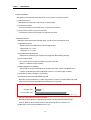
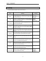
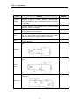
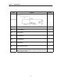
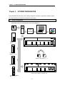

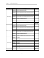

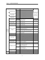
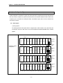
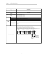
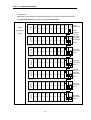
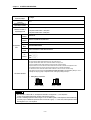
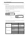

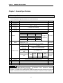
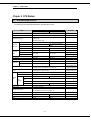

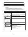
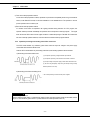
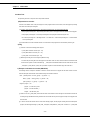
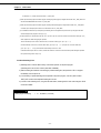
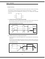
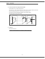
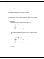

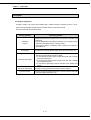
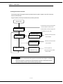
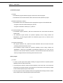
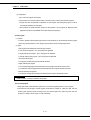
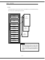


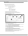
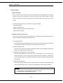
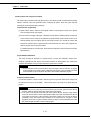
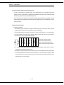

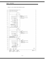
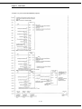
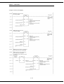
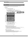
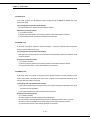

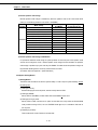
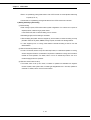
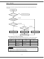
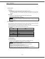
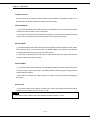

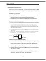
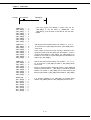


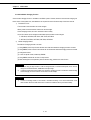
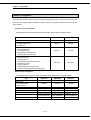


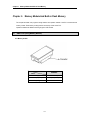

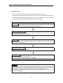
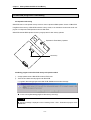
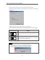
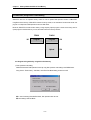
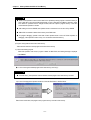
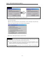

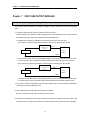
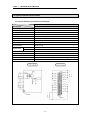
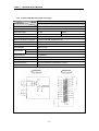
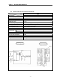
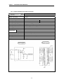
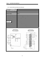

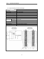
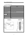
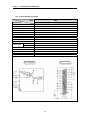
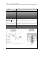
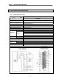
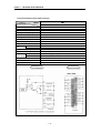
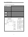
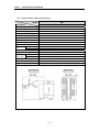
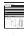
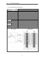
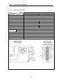
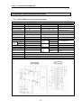
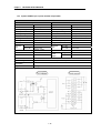
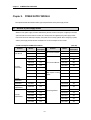


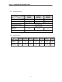
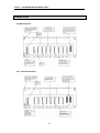
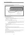

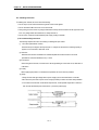
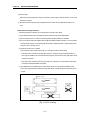

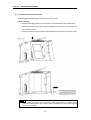
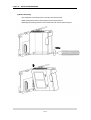
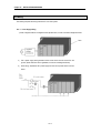
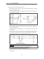
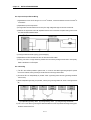

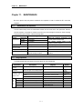
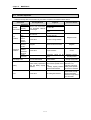
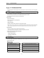
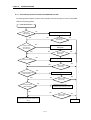
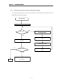
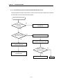
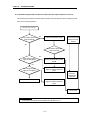
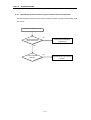

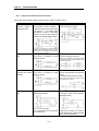
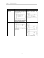
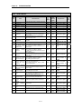
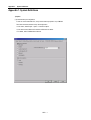
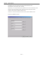
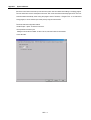
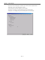
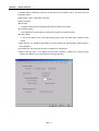
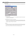

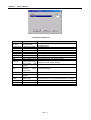
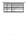
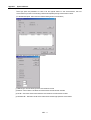


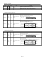
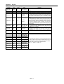
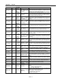

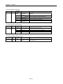
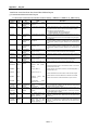
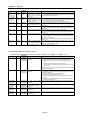
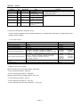


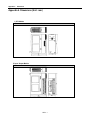
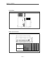
![[13] Chap.11 Trouble Shooting](http://vs1.manualzilla.com/store/data/005753222_1-b84b48489eb920e39ff2c53b244a8bf5-150x150.png)