1
Reset
A/0
w=0
w=1
1
B/0
F/0
0
w=0
1
1
0
G/0
C/0
w=0
D/0
1
0
1
0
w=0
0
1
H/0
1
E/1
I/1
1
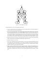
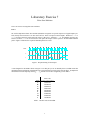
Figure 2. A state diagram for the FSM.
Design and implement your circuit on the DE2 board as follows.
1. Create a new Quartus II project for the FSM circuit. Select as the target chip the Cyclone II EP2C35F672C6,
which is the FPGA chip on the Altera DE2 board.
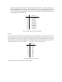
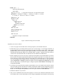
2. Write a Verilog file that instantiates the nine flip-flops in the circuit and which specifies the logic expressions
that drive the flip-flop input ports. Use only simple assign statements in your Verilog code to specify the
logic feeding the flip-flops. Note that the one-hot code enables you to derive these expressions by inspection.
Use the toggle switch SW0 on the Altera DE2 board as an active-low synchronous reset input for the FSM,
use SW1 as the w input, and the pushbutton KEY 0 as the clock input which is applied manually. Use the
green LED LEDG0 as the output z, and assign the state flip-flop outputs to the red LEDs LEDR 8 to LEDR0 .
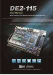
3. Include the Verilog file in your project, and assign the pins on the FPGA to connect to the switches and the
LEDs, as indicated in the User Manual for the DE2 board. Compile the circuit.
4. Simulate the behavior of your circuit.
5. Once you are confident that the circuit works properly as a result of your simulation, download the circuit
into the FPGA chip. Test the functionality of your design by applying the input sequences and observing
the output LEDs. Make sure that the FSM properly transitions between states as displayed on the red LEDs,
and that it produces the correct output values on LEDG 0 .
6. Finally, consider a modification of the one-hot code given in Table 1. When an FSM is going to be implemented in an FPGA, the circuit can often be simplified if all flip-flop outputs are 0 when the FSM is in
the reset state. This approach is preferable because the FPGA’s flip-flops usually include a clear input port,
which can be conveniently used to realize the reset state, but the flip-flops often do not include a set input
port.
2