1
PROCEDURE
RAS356B
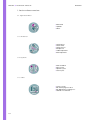
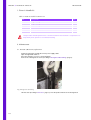
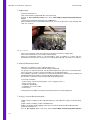
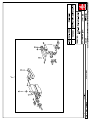
2.3. Unloading area:
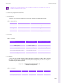
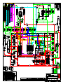
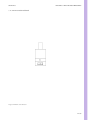
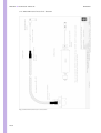
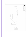
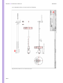
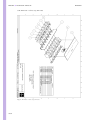
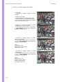
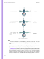
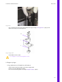
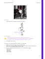
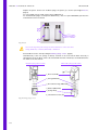
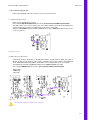
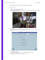
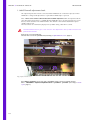
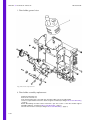
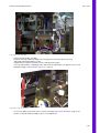
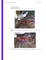
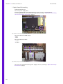
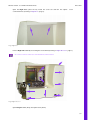
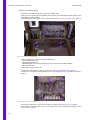
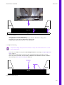
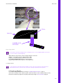
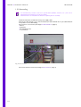
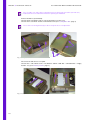
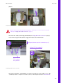
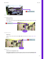
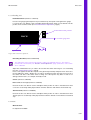
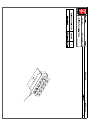
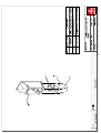
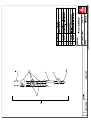
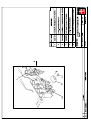
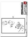
Rack End Transfer (reference: CAE011A).
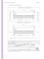
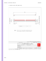
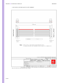
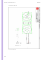
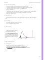
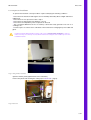
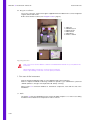
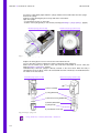
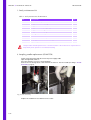
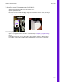
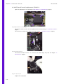
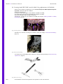
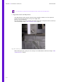
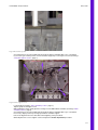
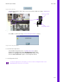
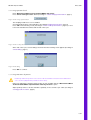
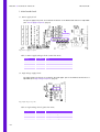
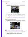
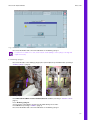
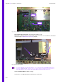
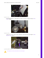
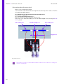
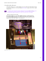
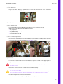
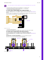
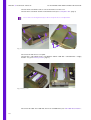
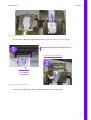
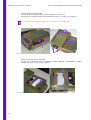
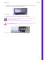
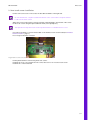
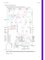
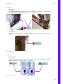
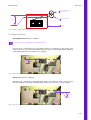
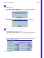
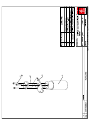
Put a 0.5 mm gauge against Ejection Tray mechanical stop, then push a rack against this gauge.
Loseen the two CHC M2x10 screws and adjust Rack End Transfer switch to have detection in this
position, then screw the switch (See “Rack end transfer adjustment”, page 9).
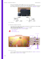
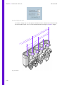
Switch in detection position
RACK
Put a 0.5 mm gauge here
Ejection Tray
0.5 mm
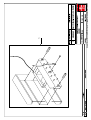
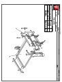
Diag.18 Rack end transfer adjustment
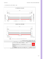
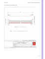
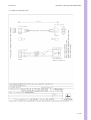
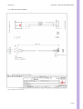
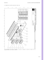
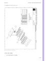
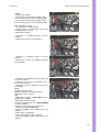
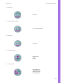
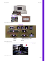
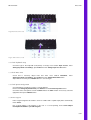
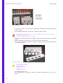
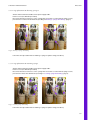
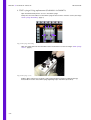
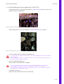
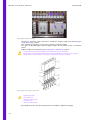
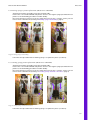
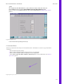
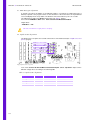
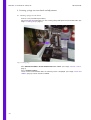
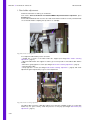
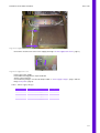
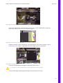
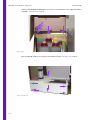
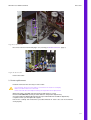
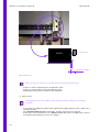
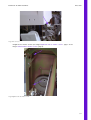
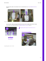
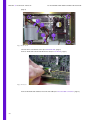
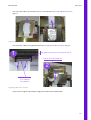
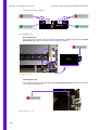
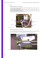
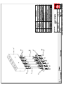
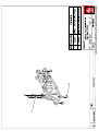
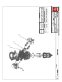
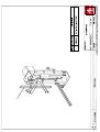
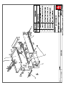
Unloading Area Full (reference:XDA742AS)
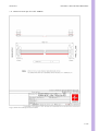
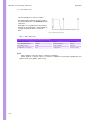
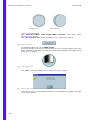
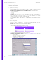
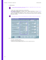
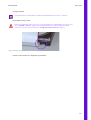
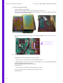
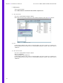
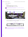
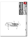
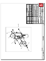
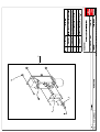
This adjustment is the same that Stop Rack Loading Left and Right Sensors. The switch is
prestressed on the bracket (See “Bracket / switch adjustment”, page 7).Reference of the switch
alone: CAE019A.
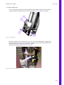
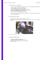
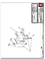
Adjust the switch/bracket assy in order to be sure that the switch axle hang not out of unloading
tray (See “Switch wheel position”, page 6).
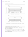
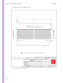
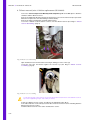
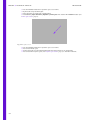
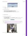
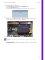
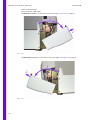
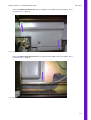
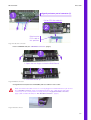
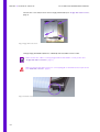
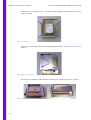
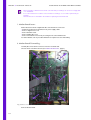
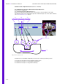
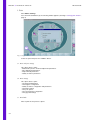
Press a rack against the left side of Ejection Tray (thermic panel side) and push it from the front to
the rear. Adjust the switch / bracket assy in order to get detection when the rack comes in front of
the switch. The Axle of the switch must not hang out of the Ejection Tray Plate in order to not
damage switch if rack is, for example, manually moved.
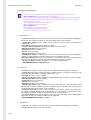
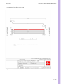
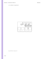
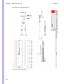
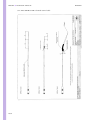
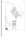
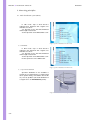
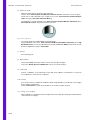
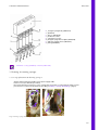
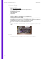
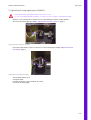
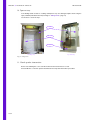
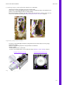
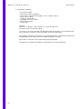
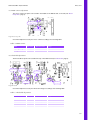
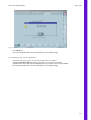
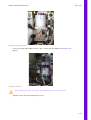
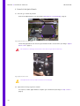
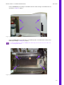
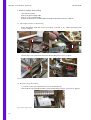
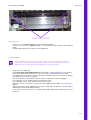
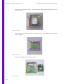
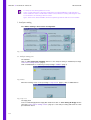
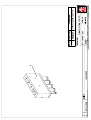
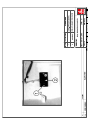
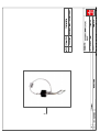
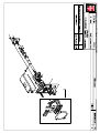
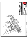
Covers (reference: CAE020A).
Front cover, left and right (reference: CAE020A).
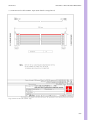
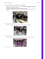
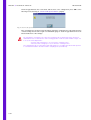
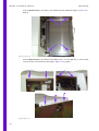
Unscrew the two CHC M3x12 screws and adjust switch position in order to have detection when
covers are closed. Keep a little play beetween switches detection and switches mechanical stop.
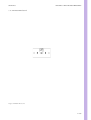
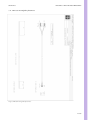
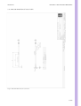
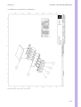
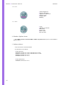
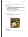
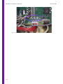
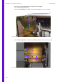
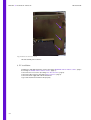
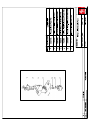
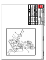
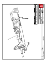
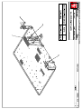
Thermic Panel (reference: CAE006A).
Unscrew the two CHC M2x10 screws and adjust switch position in order to have detection when
Thermic panel is closed.Keep a little play beetween switches detection and switches mechanical
stop.
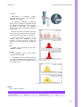
2.4. Waste:
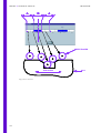
Waste Control:
No adjustment available.
9/10