1
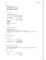
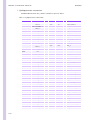
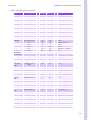
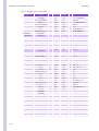
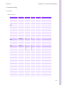
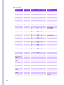
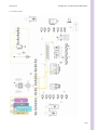
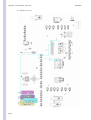
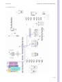
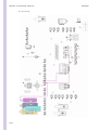
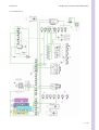
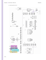
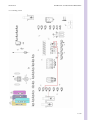
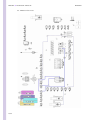
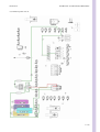
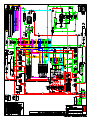
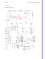
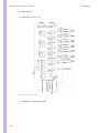
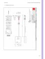
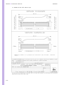
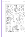
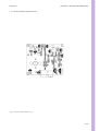
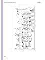
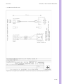
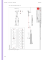
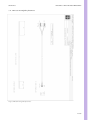
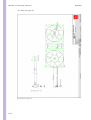
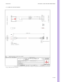
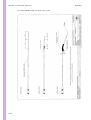
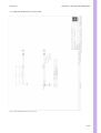
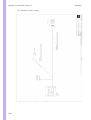
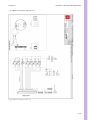
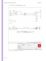
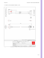
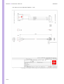
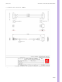
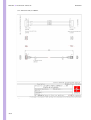
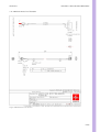
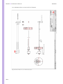
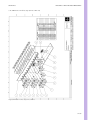
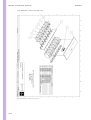
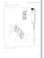
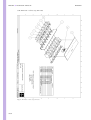
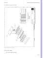
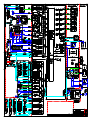
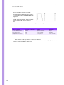
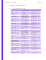
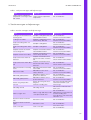
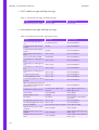
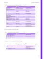
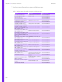
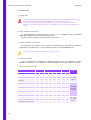
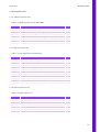
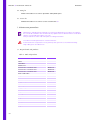
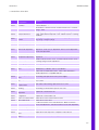
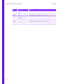
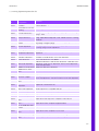
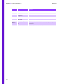
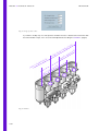
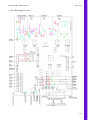
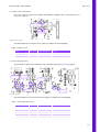
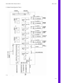
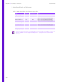
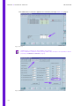
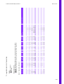
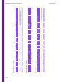
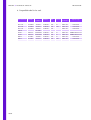
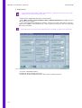
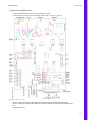
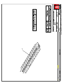
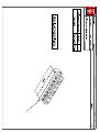
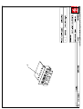
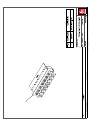
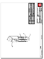
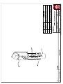
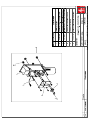
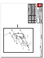
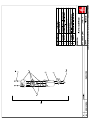
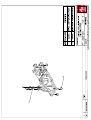
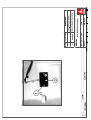
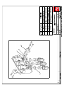
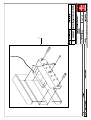
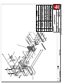
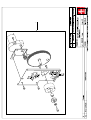
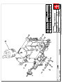
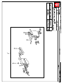
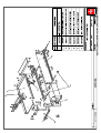
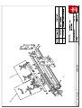
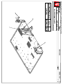
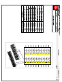
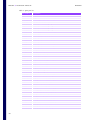
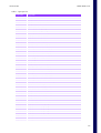
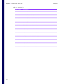
SECTION 2
HYDRAULIC & PNEUMATIC PRINCIPLES
Table 1: Hydropneumatic connection
Circuit
From
F.S. Diameter
1.52
760
T7_1
LV23_2
1.52
300
Probe rinse block_2
LV22_2
1.02
115
Sample syringe_2
LV11_2
1.52
440
LV25_3
LV25_1
1.52
65
LV27_3
LV27_1
1.52
50
LV26_1
1.52
200
1.52
160
1.52
260
S
LV26_2
Reagent heater_2
ABX EOSINOFIX REAGENT
S
SAMPLING
RBC chamber_1
S
Reagent heater_1
160
DIL1/HGB chamber_1
1.52
50
T10_2
LV25_2
1.52
170
WBC/Baso chamber_4
Abx Cleaner bottle
2.05
800
LV8_1
LV8_3
2.05
160
Reagent syringe_2
LV8_2
1.52
70
LV6_3
LV6_1
1.52
300
T10_3
T10_1
1.52
180
WBC/Baso chamber_1
LV6_2
1.52
120
T5_3
Abx Eosinofix bottle
2.05
800
LV9_1
LV9_3
2.05
160
Reagent syringe_3
1.52
550
1.52
160
LMNE chamber_3
Abx Basolyse II
bottle
2.05
800
LV12_1
LV12_3
2.05
160
LV12_2
1.52
575
S
Reagent heater_10
S
Reagent heater_11
S
S
Reagent heater_3
Reagent syringe_5
Reagent heater_9
S
1.52
60
Reagent heater_12
S
1.52
160
WBC/Baso chamber_2
Abx Alphalyse bottle
1.52
800
LV7_1
LV7_3
1.52
160
Reagent syringe_1
LV7_2
1.52
480
DIL1/HGB chamber_2
Probe_1
1.02
205
Probe_1
LMNE COUNTING
Reagent heater_7
1.52
LV9_2
ABX ALPHALYSE REAGENT
LV26_3
S
LV27_2
Reagent heater_4
ABX BASOLYSE II REAGENT
T.S. To
LV20_2
Reagent heater_8
ABX CLEANER
REAGENT
Length
Sample syringe_1
S
Sample syringe_1
LMNE chamber_4
1.30
20
M4_2 photocell
M4_1 photocell
1.30
320
LV4_1
LV4_2
1.02
130
T2_2
T2_3
1.02
250
LMNE syringe_5
LMNE syringe_3
1.14
85
T4_1
T4_2
1.02
15
LV5_1
LV5_2
1.52
280
T7_2
1.85
10
LMNE flow cell_6
0.19
4
LMNE flow cell_6
T2_1
S
3/18