1
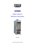
4 DIGITAL FLOW SENSOR
with 1~2 ALARMS / ANALOG OUTPUT / RS-485
GSFL53
MANUAL
PROGRAMMING MODE OPERATING PROCEDURES
D
Please understand key indicators & functions at the first operation.
FRONT PANEL, KEY FUNCTIONS & WIRING CONNECTION
Alarm 1 Indicator
Alarm 2 Indicator
Remark:
In any measuring pages,
press ENT for 3 secs can
go back to the previous
page and save the parameters
after modification.
1
AL
2
3
4
Measuring Status
Press
5
POWER:15~30Vdc
1
2
3
OUTPUT:4~20mAdc
4
ENT
Enter Pass Code
5
Wiring connection
6
8
2
3
5
Press ENT 3 sec Pres s ENT 3 sec
Power wiring connection for analog output
1
7
+
A
-
+
P
-
1
7
6
8
2
+
A
-
3
5
RS-485 Setting
Group
Alarm Setting
Group
System Setting
Group
A/O Zero
Adjustment
Address Setting
Alarm 1 Setpoint
Setting
K Factor Decimal
Point Setting
A/O Span
Adjustment
Baud Rate
Setting
Alarm 2 Setpoint
Setting
K Factor Setting
Parity Check
Setting
AL1 Action
Setting
A/O Hi
Scale Setting
Flow Unit
Setting
Frame Setting
AL2 Action
Setting
A/O Low
Scale Setting
Total Time Unit
Setting
Pass Code
Setting
Decimal Point
Setting
4
4
M12 Connector
1
2
3
4
5
6
7
8
COLOR
Power wiring connection for RS-485
DESCRIPTION
Brown Power : 15~30V
Red
Output :4~20mA
White Common
Blue
RX : D+
Green TX : DYellow C1 / E1
Purple C2 / E2
Black
Ecom / Ccom
Key Name Symbol
1
7
6
8
2
3
5
4
+
P
-
Descriptions
1. In the measuring status, press this key can enter to parameter pages.
2. In the parameter setting, press this key for 3 sec can save the value
& go to next parameter.
AL Start Delay
Time Setting
AL1 Hysteresis
Setting
Shift Key
1. In the parameter setting , press this key can move the cursor left.
AL Start Band
Setting
AL2 Hysteresis
Setting
Key Lock Setting Sampling Time
Setting
Up Key
1. In the parameter setting, press this key can increase the digits.
AL2 Run Delay
Setting
AL1 Run Delay
Setting
Display Low Cut Display Average
Setting
Setting
Enter Key &
Save Key
Down Key &
A/O Adjusting Key
Enter Pass Code
Pass Code Error
Operation Key
PIN
3 sec
IN GND
EXC+5V
ENT
Press
ENT
1. In the measuring status, press this key for 3 sec can enter to
analog output adjustment.
2. In the parameter setting , press this key can decrease the digits.
SYSTEM (SYS) SETTING GROUP PROCEDURE
D
While Pass Code is correct, Press ENT for 3 sec can select SYS Setting Group.
Display
Default
Descriptions
Name
K Factor Decimal 1. Press ENT to enter this parameter, press↑or↓can modify
the K Factor decimal point.
Point Setting 2. Press ENT for 3 SEC to save the parameter and go to the
(dPk)
next parameter
1. Press ENT to enter this parameter, press↑or↓can modify
K Factor
the K Factor range
Setting
2. Press ENT for 3 SEC to save the parameter and go to the
(kF)
next parameter
Flow Unit 1. Press ENT to enter this parameter, press↑or↓can modify
the flow unit: Leter, Gal,M3, CC
Setting
2. Press ENT for 3 SEC to save the parameter and go to the
(unit)
next parameter
Total Time 1. Press ENT to enter this parameter, press↑or↓can modify
time unit: sec, min, hour, day, month
Unit Setting 2. the
Press ENT for 3 SEC to save the parameter and go to the
(C.tiME)
next parameter
1.
Rate Decimal Press ENT to enter this parameter, press↑or↓can modify
the rate decimal point.
Point Setting 2. Press ENT for 3 SEC to save the parameter and go to the
next parameter
(dP)
Sampling Time 1. Press ENT to enter this parameter, press↑or↓can modify
the sampling time.
Setting
2. Press ENT for 3 SEC to save the parameter and go to the
(tbASE)
next parameter
Display Average 1. Press ENT to enter this parameter, press↑or↓can modify
the display average. (1~99)
Setting
2. Press ENT for 3 SEC to save the parameter and go to the
(AvG)
next parameter
Display Low Cut 1. Press ENT to enter this parameter, Press ↑or↓can modify
the value, range: 0~99
Setting
2. Press ENT for 3 SEC to save the parameter and go to the
(LCUt)
next parameter
ALARM (roP) SETTING GROUP PROCEDURE
D
While Pass Code is correct, Press ENT for 3 sec can select ROP Setting Group.
Display
Default
Name
Alarm 1 Setpoint Example:
1. The alarm is on while the display is 50.0, the value must be
Setting
set for 50.0
(Al1)
Press ENT to enter this parameter,
Press ENT again to move the digit.
Alarm 2 Setpoint
Press ↑or↓can modify the value, range: 0~9999
Setting
2. Press ENT for 3 SEC to save the parameter and go to the
next parameter
(Al2)
Description: Hi: Alarm on while the display higher than setpoint.
AL1 Action
Lo: Alarm on while the display lower than setpoint.
Setting
Range: Hi (≧ Alarm setpoint ), Lo (< Alarm setpoint )
(ACt1)
1. Press ENT to enter this parameter, press↑or↓can modify
AL2 Action
the value.
Setting
2. Press ENT for 3 SEC to save the parameter and go to the
next parameter
(ACt2)
Description:
AL1 Hysteresis 1. If the Alarm actions is Hi, the display must lower than
(Setpoint-HYS) value, the Alarm will be off.
Setting
2. If the Alarm actions is Lo, the display must lower than
(HYS1)
(Setpoint+HYS) value, the Alarm will be off.
3. Press ENT to enter this parameter.
AL2 Hysteresis
Press ENT again to movethe digit.
Setting
Press ↑or↓can modify the value, range: 0~99
4. Press ENT for 3 SEC to save the parameter and go to the
(HSY2)
next parameter
Description:
1. If the value is 5, while the display reaches the Alarm setpoint,
Alarm will be on after 5 sec.
2. Press ENT to enter this parameter.
Press ENT again to movethe digit.
AL2 Run Delay
Press ↑or↓can modify the value, range: 0~99(sec)
Setting
3. Press ENT for 3 SEC to save the parameter and go to the
(dEL2)
next parameter
AL1 Run Delay
Setting
(dEL1)
1. Press ENT to enter this parameter, press ↑or↓can modify the
Key Lock Setting
value, range: no(unlock),YES(lock)
(LoCk)
2. Press ENT for 3 SEC to save the parameter and go to the
next parameter
1. Press ENT to enter this parameter, press ↑or↓can modify
Pass Code Setting the value, range: 0~9999
(CodE)
2. Press ENT for 3 SEC to save the parameter and go to the
next parameter
Example:
1. The display is 4.0 to output 4mA, this value must be 4.0.
A/O Low
Press ENT to enter this parameter,
Scale Setting
Press ENT again to move the digit.
Press ↑or↓can modify the value, range: 0~9999
(AnLo)
2. Press ENT for 3 SEC to save the parameter and go to the
next parameter
Example:
1. The display is 100.0 to output 20mA, this value must be 100.0.
A/O Hi
Press ENT to enter this parameter,
Press ENT again to move the digit.
Scale Setting
Press ↑or↓can modify the value, range: 0~9999
(AnHi)
2. Press ENT for 3 SEC to save the parameter and go to the
next parameter
Descriptions
AL Start Band
Setting
( Sb)
Description:
1. If the value is 5, if the display is under 5, Alarm will not be ON.
2. If this value is5, while the display reaches the Alarm start band
range, the Alarm will be on after Sdt time.
3. Press ENT to enter this parameter.
Press ENT again to movethe digit.
Press ↑or↓can modify the value, range: 0~99(sec)
3. Press ENT for 3 SEC to save the parameter and go to the
next parameter
※This function can prevent the wrong action by starting current
AL Start Delay
Time Setting
( Sdt)
Description:
1. While the dispaly reach the Alarm start band range, the Alarm
will be on after this time.
(P.S. :This parameter must be use with Sb together)
3. Press ENT to enter this parameter.
Press ENT again to movethe digit.
Press ↑or↓can modify the value, range: 0~99(sec)
3. Press ENT for 3 SEC to save the parameter and go to the
next parameter
RS-485 (doP) SETTING GROUP PROCEDURE
D
While Pass Code is correct, Press ENT for 3 sec can select RS-485 Setting Group.
Display
Default
Descriptions
Name
Address Setting
(Addr)
Baud Rate
Setting
(bAUd)
Parity Check
Setting
(PAri)
Frame Setting
(FrAM)
1. Press ENT to enter this parameter,
Press ENT again to move the digit.
Press ↑or↓can modify the value, range: 0~255
2. Press ENT for 3 SEC to save the parameter and go to the
next parameter
1. Press ENT to enter this parameter,
Press ↑or↓can modify the value, range: 96400,4800,
2400(bps)
2. Press ENT for 3 SEC to save the parameter and go to the
next parameter
1. Press ENT to enter this parameter, Press ↑or↓can modify
the value, range: n.8.2., n.8.1., EvEn, odd
2. Press ENT for 3 SEC to save the parameter and go to the
next parameter
1. Press ENT to enter this parameter, Press ↑or↓can modify
the value, range: on (Hi->> Lo), off (Lo->>Hi)
2. Press ENT for 3 SEC to save the parameter and go to the
next parameter
A/O SETTING
D
Press↓for 3 sec can enter to P.Cod page, if the pass code is correct, Press ENT for 3 sec can enter to DISPLAY SETTING.
Display
Default
Name
Descriptions
A/O Zero
Adjustment
( AZEr)
1. Press ENT to enter this parameter, the digit will be flashed.
2. Press ENT again to move the digit, Press ↑or↓can modify
the value, Move the digit to the 3rd or 4th digit to increase the
speed of adjustment.
3. Press ENT for 3 SEC to save the parameter and go to the
next parameter
A/O Span
Adjustment
( ASPA)
Error Code of Self-Diagnosis
Display
Descriptions
Input signal is over display range (Max 9999)
Input signal is under display range (Min -1999)
EEPROM reading/writing suffers the interference (about 1 million times).
**Please check the wiring connection is correct first, if the problem still exist, please return the meter
to the factory.
GSFL53 Modbus RTU Mode Protocol Address Map)
Data: 16Bit / 32Bit, +/- is 8000~7FFF (-32768~32767), 80000000~7FFFFFFF(-2147483648~2147483647)
Modbus
40001
40002
40003
40004
40005
40006
40007
40008
40009
40010
40011
40012
40013
40014
40015
40016
40017
40018
40019
40020
40021
40022
40023
40024
40025
40026
40027
HEX
0000
0001
0002
0003
0004
0005
0006
0007
0008
0009
000A
000B
000C
000D
000E
000F
0010
0011
0012
0013
0014
Name
Nescriptions
DISPLY
KF
ANLO
ANHI
TBASE
AL1
AL2
TOTAL
Current display, range:0000~270F(0000~9999)
K factor setting, range:0001~270F(0001~9999)
Analog output low scale setting; range: 000~270F(0000~9999)
Analog output hi scale setting; range: 000~270F(0000~9999)
Sampling time base setting; range: 0001~270F (0001~9999)
Alarm 1 setpoi nt setting; range : 000~ 270F( 0000 ~999 9)
Alarm 2 setpoi nt setting; range : 000~ 270F( 0000 ~999 9)
Alarm total, range:0000~5F5E0FF(0000~9999)Hi Bit
Alarm total, range:0000~5F5E0FF(0000~9999)Low Bit
Display average setting; range: 0001~0063 (1~99)
Display low cut setting; range: 0000~0063 (00~99)
Alarm 1 hysteresis setting; range: 0000~00 63 (00~99 )
Alarm 2 hysteresis setting; range: 0000~00 63 (00~99 )
Alarm 1 act del ay time setting; rang e: 0000~ 0063 (0~9 9)
Alarm 2 act delay time setting; range: 0000~00 63 (0~9 9)
Alarm start band setting; range: 000~0063 (0~99)
Alarm 1 start delay time setting; ran ge: 0000~0063 (0~ 99)
Address setting; range: 0000~00FF (0~255)
AlarmK factor decimal point setting, range:0000~0003(0~1)0:0, 1:1, 2:2, 3:3
Decimal point settin g; range: 0000~0003 (0~1) 0:0, 1:1, 2:2, 3:3
Linear-Speed unit setting: 0:M3, 1:Liter, 2:C.C, 3:GAL
0015 CTIME Total time unit setting; range: 0000~0004(0~4)
0:SEC,1: Min, 2:HoUr, 3:dAY, 4:MontH
0016 ACT1 Alarm 1 act setting; ran ge 0000~0001(0~ 1) 0:Lo, 1:Hi, 2:P-ON
0017 ACT2 Alarm 2 act setting; ran ge 0000~0001(0~ 1) 0:Lo, 1:Hi
0018 BAUD Baud rate setting; ran ge: 0000~0002 (0~ 2) 0:2400, 1:4800, 2:9600
0019 PARI Parity setting; range: 0000~0003 (0~3), 0:N.8.2., 1:N.8.1., 2:EVEN, 3:ODD
001A FRAME Fram e set ting; rang e 000 0~0 001 (0~1 ) 0:off , 1:on
AVG
LCUT
HYS1
HYS2
DEL1
DEL2
SB
SDT
ADDR
DPK
DP
Unit
Act
R
R/W
R/W
R/W
R/W
R/W
R/W
R/W
R/W
R/W
R/W
R/W
R/W
R/W
R/W
R/W
R/W
R/W
R/W
R/W
R/W
R/W
R/W
R/W
R/W
R/W
R/W