1
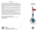
The FP7 BeyWatch European scientific project: general
features and design criteria of the Combined Photovoltaic
Solar (CPS) system within the BEYWATCH system
architecture
G. Fertitta, C. Giaconia, D. La Cascia, F. Lo Bue, R. Miceli IEEE Member, C. Rando
Università di Palermo - Dipartimento di Ingegneria Elettrica, Elettronica e delle Telecomunicazioni
Italy Parco d’Orleans, Viale delle Scienze s.n.c. – 90128 Palermo (Italia)
[email protected]
Copyright © 2011 MC2D & MITI
Abstract: This paper includes the general features and design criteria of a combined photovoltaic
solar system (CPS) and its allocation within the entire architecture of the BeyWatch system. The CPS
main functionalities and characteristics, the description of the CPS main components and the CPS
electronic control and monitoring subsystem, together with the description of the Firmware design
and communication protocols are here reported. The Combined Photovoltaic and Solar system (CPS)
is a Renewable Energy system that produces thermal and electrical energy and the design has been
based on a modular approach.
Keywords: BEYWATCH (Building EnergY WATCHer), CPS (Combined Photovoltaic Solar)
System, grid, hot water, electrical energy, ZigBEE, Wireless Sensor Networks.
1. Introduction
Targeting environmental sustainability, energy
efficiency and new power distribution production business models, BeyWatch research
European project has designed, developed and
is evaluating an innovative, energy-aware and
user-centric solution, able to provide intelligent
energy monitoring - control and power demand
balancing at home-building & neighbor level
[1]. The system interconnects legacy
professional - consumer electronic devices with
a new generation of energy-aware white-goods,
where multilevel hierarchic metering, control,
and scheduling are applied, based on power
demand, network conditions and personal
preferences. Moreover, via a combined
photovoltaic - solar system, it is able to produce
hot water and electric energy, which can be
used at home or at peak hours fed to the
electricity network [2]. Besides the research and
technological objectives, BeyWatch has built
one user centric energy delivery, consumption
and production platform, is able to motivate a
gradual change in the every-day energy
consumption patterns of the typical consumer,
towards a smoother power demand curve, and
much reduced energy waste, while on the other
hand, to enable new business models and
flexible power consumption - generation
contracts, creating new social interaction and
targeting social acceptance of energy efficient
buildings. One component of the BeyWatch
platform is constituted a Combined and
Photovoltaic System (CPS) made of both
photovoltaic panels (for electricity) and solar
panels (for hot water) [3]. This paper deals with
the design and the set up of a new small scale
CPS system which has been prototyped,
optimized and integrated in BeyWatch
architecture. The prototype is able to integrate
the electric energy generation with the hot water
production. The CPS provides an important step
beyond state of art by implementing the
following features: Integrate the thermal and
electric energy generation to increase energy
efficiency in its consumptions in household
appliances; Integration, by means of massive
ICT employment, with energy-aware white
goods for providing sanitary hot water also for
those devices; Integration with BeyWatch
architecture
for
implementing
energy
management rules [4].
BeyWatch in-home architecture is shown in the
following Figure 1.
2. CPS general features, design criteria
and architecture [5]
The general features and design criteria of the
CPS are the following.
Minimizing CPS Occupied Area: the CPS
panels footprint have been designed so that it’s
surface is as small as possible and with this aim
the CPS system components have been chosen
with the highest efficiency ratio.
Taking advantage of incentives: the CPS plant
allows the final user to enjoy the use of
incentive tariffs so all the CPS components
meet quality certifications and target minimum
efficiency during their life cycle. Moreover the
integration with existing home plants respects
National and European technical standards.
Having a fully architectural integration: the PV
panel must be well integrated from an
architectural point of view in order to preserve
the home appearance, especially in some
protected or historical areas. Infact, in many
countries the integrated plants receive more
incentives than the non-integrated ones.
Minimizing CPS plant cost and investment
payback period: the investment cost must be
recovered in the shortest period of time so the
designed smart CPS system allows either a
faster investment retrieving, either a reduction
of the components cost.
Reaching compatibility: The CPS is compatible
with existing home electrical and water
networks. So the CPS is compatible with the
most diffused existing home plants, especially
waterworks.
Having clear User Manual and Maintenance
Scheduling: a clear user manual have been
provided in order to allow the user to operate
the system, to easily identify its malfunctions
and to define the frequency and the quality of
maintenance services.
The in-home components of the BeyWatch
system are: the Combined Photovoltaic and
Solar (CPS) system; the BeyWatched Washing
Machine; the BeyWatched Dishwasher; the
BeyWatched Refrigerator and Freezer; the
Smart Metering Device; the Electricity
Watchers; The BeyWatched Residential
Gateway; A conceptual overview of the
Figure 1: The CPS in-home components in
BeyWatch architecture
3. CPS main functionalities and
characteristics
The Combined Photovoltaic and Solar system
(CPS) is a Renewable Energy System (RES)
that supplies hot water for the in-home energyaware white goods, mainly in order to reduce or
to cancel the internal heating cycles, and for
general sanitary use; this strongly reduces the
home electrical energy utilization and CO2
emissions, as a direct consequence [6]. The CPS
also generates electrical energy to be used under the user/agent control and thanks to its
high performance ICT features that allow a
strong communication between the PV system,
the solar system and the Agent, - into the home
in order to decrease electric energy requests
from the grid during the peak times or when
electrical energy may become too expensive.
The generated electrical power can be fed into
the electrical distribution network or, depending
on the business model adopted by energy
providers, it can eventually end up in a direct
profit for the user. The preferred “destination”
of the generated electricity is explicitly
dependant on specific regional market
constraints (France, Spain, Italy, etc.): the
BeyWatch platform takes into account this
flexibility requirements [7]. The CPS design has
been based on a modular approach whose
minimum cell considers a PV (photovoltaic)
panel with about 1kWp of nominal peak
electrical power. As for the thermal production,
the CPS considers a modular design based on a
200 liters hot water tank within a temperature
range spanning between 35° and 75°C. These
values can be changed according to the amount
of needed thermal and/or electrical energy and
on the CPS physical location. The CPS behaves
as an intelligent module, able to communicate
with the BeyWatch Agent, via a wireless
medium, in order to act according to energy
management rules. The internal control logic
has been based on low power embedded
microcontrollers thus providing the needed
processing power to control the CPS relevant
parameters, to log all of them for a minimum
required time interval and to implement the
wireless communication with the Agent [5]. In
particular, electrical energy from the PV panel
can also be used to heat water in case of hot
water demand. This is done according to the
decisions taken by the BeyWatch Agent. All the
above described functions have been
implemented with a single microcontroller
based board, acting as a master board and in
charge of all the communications with external
elements to the CPS. Two slave boards
responsible for the control and the logging
actions on the CPS subsystems such as the
Photovoltaic panel, the Solar collector, the hot
water Tank etc. The slave boards will also be
processor
based
and
will
internally
communicate with the master board via a wired
medium. The CPS system functionalities are
presented in Figure 2.
Figure 2: CPS system functionalities
4. CPS components description
The CPS is made up by a PV system and a
Solar Thermal (ST) System. The main
components of the PV system are the PV panel
and the PV Inverter, while the main components
of solar thermal system are the Solar Collector,
the solar station and the solar Tank. The PV
panel consists of a system able to produce about
1300 Wp max electrical power. The PV inverter
is grid connected and synchronizes to the AC
grid electrical frequency. The inverter is
equipped with a Maximum Power Point
Tracking (MPPT) system able to maximize the
power generated. The Solar Collector (also
called “S-T panel”) is able to heat the water
inside the solar tank up to a temperature of 75
°C. The total solar collector surface is of about
6.6 square meters and is composed of two
modules. The solar station is able to implement
the forced circulation of the thermo vector fluid
inside the solar collector and the tank for its
temperature control.
A. The PV System.
It is constituted of a string made of six series
connected modules. Each module has a peak
power equal to 220Wp with 3% power
tolerance. Each module has the following
dimensions: 1580 mm (L) x 808 mm (W) x 35
mm (H) The PV panel string supplies a 2 kW
static DC/AC power converter. The static power
converter actuates the synchronization of the
PV voltage and frequency with the grid ones.
The table hereafter reports the PV system
technical specifications. The PV system is also
equipped with a pyranometer able to detect the
solar irradiation that enables the Agent to
connect the electric power generation historical
data with the in-home energy consumption. The
string picture and the static power converter
picture of the PV system realized are reported in
Figures 3 and 4.
B. The ST (Solar Thermal) System.
The ST system is constituted by two solar
collector modules of the EKOS factory
model DS – 24. Each module solar having
a whole net surface equal to 3,3 m2 and is
constituted by 24 heat pipes.Table 2
reports the ST system technical
specifications. The heat pipe dimensions are
58 mm of diameter and length equal 1800 mm.
The ST collector schemes are reported in the
Figure 5 and Figure 6, the ST tank scheme is
reported in Figure 7 while the hydraulic
connection scheme is shown in the Figure 8. In
Figure 9 the installed solar collector system is
shown while in Figure 10 the solar tank and
the solar station are reported.
Table 1: PV system technical specifications
#
6
1
1
2
10
m
1
Description
Mono-crystalline Silicon Solar Modules:
maximum power 220 W, Power tolerance 3%,
maximum power voltage 37,5 V, maximum power
current 4,95 A, open circuit voltage 44,5 V, short
circuit current 5,40 A, maximum system voltage
DC 1000 V (TUV).
Specification at STC: 1000W/m2 solar irradiance,
air mass coefficient (AM) 1,5, 25°C cell
temperature. All electrical specifications are +/3%.
Static power converter:
DC Input Parameters: Maximum DC voltage
system 600 V, DC rated voltage 360 V, MPPT
voltage range 90 – 580V, rated current 10 A,
maximum short circuit current 12 A.
AC Output Parameters: AC rated voltage 230 V,
AC rated frequency 50 Hz, maximum output
current 10 A (rms), rated AC power 2000 W at
40°C ambient temperature, maximum over current
protection 16 A.
Range operational temperature from -20°C to
+55°C.
International Protection (IP65)
Frame for the modules anchorage on horizontal
roofs are equipped with ballast, aluminium
modules frame work, attaching system and
brackets.
Multicontact connectors pairs
DC Solar cables 2x4mm2
pyranometer
Figure 7: The tank scheme
Figure 3: The string picture of the PV system
Figure 8: The hydraulic connection scheme
Table 2: ST system technical specifications
Figure 4: The PV system static power converter
Figure 5: The module front scheme of the ST solar
collector
Figure 6: The solar collector module lateral scheme
#
Description
2
Modular Vacuum Solar collector, model DS - 24:
Each modular collector has aperture area 3,3 m2
with 24 heat pipes, each heat pipe dimensions is
58 mm (diameter) and 1800 mm (length).
1
Temperature Probe for the Vacuum Solar
collector
2
Temperature Probe for the Solar tank
1
Solar tank:
200 liters capacity, rigid polyurethane insulation,
1380mm height, 550 mm diameter, pressure range
from 0 bar to 8 bar, maximum pressure 12 bar,
maximum temperature 95°C, mixing coefficient
12%, internal exchanger with 1m2 surface.
1
Solar station (Back device with solar gear case):
- Safety and insulation systems for the pipes;
- circulation pump,
- safety valve 6 bar,
- manometer 10 bar,
- water faucets,
- thermometers,
- flow rate measurer.
2
Fastener clamp for horizontal roof
2
Expansion tank 18 liters
30 Antifreeze for vacuum solar collectors
l
1
Thermostatic valve
1
Safety valve for sanitary hot water 6 BAR
1
Electric Resistor 230 W, single phase feeding.
1
Electric board for the electric resistor driving
including a single phase differential
magnetothermic 16 A switch
1
Steel Solar pipes
The connection scheme of the PV generator to
the public low voltage grid is reported in Figure
11 according to the CEI 11-20 standard. Table 3
summarizes the measures which are monitored
on the CPS system and which are logged to
control it and which are sent to the BeyWatch
Agent.
Figure 10: The ST system
Figure 9: The ST Solar Collector system.
Table 3: CPS data to be monitored
Measured
quantity
Temperature
AC Voltage
AC Current
DC Current
Temperature
Temperature
Measured
abbreviation
Tpv
Vac
Iac
Icc
Tst
Tsc
Solar
irradiation
S.i.
Position on the
CPS
PV panel
Inverter
Inverter
Inverter
Solar Tank
Solar Collectors
Module
Pyranometer
5. CPS electronic control and
monitoring
As already stated, the input data for the CPS
are collected through several sensors located
near the main parts of the system, by using a
tailored designed and implemented slave
boards. The Photovoltaic and Solar Thermal
panels and the electric inverter and the hot
water tank are likely placed on the roof of the
authors’ Department. Thus the electronic
master micro control and monitoring system
acts as the main device responsible of the
wireless communication with the agent via an
integrated ZigBee transceiver [8], while two
Slave Micro (located on the roof) send
monitored data via an RS485 wired
communication system implemented within
the same microcontroller, to the receiving
Master micro that in turn collects them to be
ready for the BeyWatch agent upon request.
From the hardware point of view, the CPS is
composed by three boards with the following
characteristics and equipments:
Master Micro Board: ZigBee transceiver, 8051
based micro controller and RS 485
Transceiver.
Slave Micro 1 - Boiler Board : 4 ADC inputs
for Temp. sensing, 1 Electric Heater Bypass
Circuit, 1 On/Off circuit for electric heater,
8051 based micro controller and RS 485
Transceiver.
.
Figure 11: The connection scheme of the PV
generator to the public low voltage grid
Slave Micro 2 – Photovoltaic Board: 1 ADC
input for Temperatures sensing, 1 ADC input
for PV AC current sensing, 1 ADC input for
PV AC Voltage sensing, 1 ADC input for
Solar radiation sensing, 1 ADC input for PV
DC panels current sensing, 8051 based micro
controller and RS 485 Transceiver. ach board
is then subdivided in two daughter parts, the
sensing board and the controller board. The
controller board is mounted on the sensing
board by an embedded socket
This allows the realization of a unique
controller board by giving to the sensing board
all the custom circuits and conditioning
electronics dedicated to a particular slave
micro and leaving to the controller board the
AD conversion functionalities and the
elaboration step within the embedded
microcontroller. The controller board in fact
integrates the TI CC2531 micro controller
which provides the ADC inputs and the RF
transceiver. The sensing boards instead
integrate the signal conditioning circuits and
the serial RS485 transceiver. Moreover, each
sensing board integrates two voltage
regulators, in order to provide a stabilized 5V
and 3,3V DC power supply. Although the
slave and master boards provide different
sensing circuits, the power circuit, the RF
transceiver socket and the serial interface, are
identical. Figure 12 shows a picture of the
implemented controller board.
Figure 13: CPS Monitor screenshot
7. Conclusions
Figure 12: RF controller Board (Top view)
6. Firmware design and
communication protocols
The CPS internal logic is primarily dependent
on the communication state between the
Master Micro and the Agent. Even if the
boards are capable to implement a ZigBee
node, all their parameters are visible to the
agent through the Master Micro as a unique
information source for the CPS as a whole.
Moreover all the implemented methods follow
the public defined ones of the Home
Automation standard Cluster of the Stack,
hence the CPS is a full interoperable ZigBee
wireless node. The main scenarios correspond
to presence or not of a wireless communicating
link between agent and CPS control electronic
When all is rightly working the CPS Logic
runs all the commands coming from the Agent,
this is in fact the most efficient way of
behaving, since the CPS has no direct
connection with the appliances requests neither
it can predict possible electricity and/or hot
water usage from the generic loads of the
apartment. The only command to be given to
the CPS is then: Set the target temperature for
the hot water tank (Tset). In this way the
Agent may independently decide the tank
Temperature and, if needed, the electric
resistor will be locally controlled by the Slave
board in order to speed up the tank heating
phase. When instructions do not arrive from
the Agent, due to communication link failure,
the CPS internal electronic control system
assumes a minimum service temperature
(Tbasic) as a reference, acting as in a
traditional system. As an example a screenshot
of a working CPS monitoring interface is
shown in Figure 13, where more parameters
than the ones strictly needed for the BeyWatch
Agent-CPS communication are present. Some
of them in fact are also locally monitored by
the CPS control electronics in order to
internally check the correct CPS working
conditions.
The above described CPS has been successfully
tested both from the hardware point of view, by
considering the functionalities of the single
Photovoltaic and Solar Panel, and from the ICT
point of view, by implementing the electronic
interface and running test about all the
monitored parameters and collecting them
within a simplified agent integrated within a
portable PC. CPS continuous data logging is
now routinely set up in order to observe long
term behavior of the whole system.
Acknowledgement
This publication was partially supported by the
Project BeyWatch IST-223888, which is funded by
the European Community. This work was realized
with the contribution of SDES (Sustainable
Development and Energy Savings) LaboratoryUNINETLAB - University of Palermo and MIUR.
References
[1] www.beywatch.eu;
[2] Beywatch White Paper at www.beywatch.eu;
[3] G.C. Giaconia, G. Fiscelli, F. Lo Bue, A. Di
Stefano, D. La Cascia, R. Miceli, “Integration
of Distributed on Site Control Actions via
Combined PhotoVoltaic and Solar Panels
System”,
ICCEP
2009
International
Conference on Clean Electrical Power - Capri,
Italy, 9-11 June 2009;
[4] R. Miceli, D. La Cascia, A. Di Stefano, G.
Fiscelli, C. Giaconia "Impact of Novel Energy
Management
Actions
on
Household
Appliances for Money Savings and CO2
Emissions Reduction", EVER 09 Electrical
Vehicle and Renewable Energy international
conference, Montecarlo 26th - 28th march
2009;
[5] Deliverable
D3.4
“Combined
Photovoltaic/Solar prototype”, BEYWATCH
(Building EnergY Watcher) Project no. FP7ICT- 223888, May 2010;
[6] Miceli et. Al: “Energy Management via
connected household appliances” Mc. Graw &
Hill ISBN 978-88-386-6676-6;
[7] Deliverable D5.3 “Specification of the
BeyWatch BSS architecture and components”,
BEYWATCH (Building EnergY Watcher)
Project no. FP7-ICT- 223888, March 2010;
[8] http://focus.ti.com/lit/ds/symling/cc231.pdf.