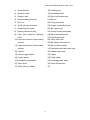
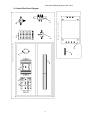
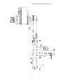
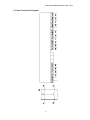
1
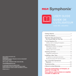
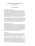
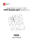
Pneumatic Sealing Machine LAS 125/2
PNEUMATIC SEALING MACHINE
LAS 125-25mm
Operating Instructions
VISTATEC
Pneumatic Sealing Machine LAS125/2
Safety Precautions
•
For safe and correct use of the machine, it is necessary to read through
these precautions carefully before use. Users should use the machine only
after having a good understanding of the safety information and
precautions.
•
All the users who operate this machine should have this user’s manual in
hand, and should keep it properly after reading for reference in the future.
•
Warning instructions provided in this manual and on the machine mean that
possible personal injury and equipment damages will be caused if relevant
requirements are not observed and corresponding measures are not taken.
•
The persons operating this machine are required to get familiar with the
steps and requirements for installation, adjustment, commissioning and
operation of this machine as well as corresponding measures taken for any
emergencies that will happen possibly, and must meet the following
conditions:
•
Having received training, able to switch on/off, earth and connect the
circuits on the machine according to the common practices and safe
operation procedures provided in this user’s manual and able to carry
maintenance, operation and protection of the machine.
Pneumatic Sealing Machine LAS 125/2
Warning!
(1) There is dangerous voltage on this machine. During operation of the
machine after power up, do not open electric cabinet door and electrical
control box to avoid possible electric shocks.
(2) This machine is provided with good earthing and its input power must
be connected to permanent fixed power lines.
(3) All the adjustment devices of the machine are adjusted to working state
before delivery. Any non-professional persons are not allowed to
change the adjustment. If any adjustment is necessary, such
adjustment should be made by professional persons.
(4) Children and other persons except operators of the machine should be
prevented from touching or access to the machine.
(5) Before installation and commissioning of the machine, please read
these safety rules and warnings carefully and all the warning labels
fixed on the machine, ensure that warning labels are located at
conspicuous positions, and replace the damaged and lost labels.
(6) Getting familiar with all the safety instructions as well as installation,
commissioning, operation and maintenance instructions provided in this
manual, and correct handling, loading/unloading and maintenance is
the reliable guarantee for the machine to be put into operation safely
and successfully.
Pneumatic Sealing Machine LAS125/2
Special Instructions
Safety Precautions before use:
1) Before starting up the machine, please check it carefully and guarantee
that there are no foreign matters under the worktable and sealing strip.
2) If any unusual conditions are found during operation, immediately press
Emergency Stop switch and then check for any faults.
3) When the sealing cylinder rises, the plastic bag is not completely cooled,
hence it should be raised slowly from one side to the other side. Never
pull it down suddenly, which will cause damage to the sealing and affect
the sealing quality.
4) If the machine is not in use, please turn off the air supply, power supply
and foot switches in time to avoid any dangers.
5) Avoid heating without plastic bags placed in position (which is called
empty sealing). Do not use high temperature without prior testing in order
to prevent damages caused to the PTFE cloth.
6) If plastics are melted and adhered to the cloth due to incorrect operation,
do not remove it by using a hard tool. Please remove it by using a soft
cloth or other soft tools. Or otherwise the PTFE cloth will be damaged and
thus there will be direct adverse effects on the sealing quality.
Pneumatic Sealing Machine LAS125/2
Contents
I. General Description ......................................................................................1
II.Definition, Functions and Overall Dimensions of the Machine....................2
III. Transportation, Installation and Storage......................................................3
IV. Maintenance ...............................................................................................4
V. Adjustment and Operation ...........................................................................4
VI. Replacement of Wearing Parts...................................................................6
VII. Troubleshooting .........................................................................................7
VIII. Safety Warnings for Operation .................................................................8
IX. Control Panel Instructions ..........................................................................8
X. Diagrams and Figure .................................................................................10
1. Assembly Drawing ............................................................................... 11
2. Control Box Parts Diagram ..................................................................13
3. Overall Dimension Drawing .................................................................15
5. Main Circuit Connection Diagram ........................................................18
6. Panel Connection Diagram..................................................................19
7. Power Supply Circuit Diagram .............................................................20
8. Main Switch Position Drawing .............................................................21
9. Pneumatic Schematic Drawing............................................................23
10. Protection Diagram ............................................................................25
11. Diagram of Protection from Pressing .................................................26
12. Fork Handling Diagram......................................................................27
13. Space and Position for Worker ..........................................................28
14. Panel Operation Position Diagram.....................................................29
15. Warning Sign Position Drawing .........................................................30
XI. Packing list ...............................................................................................31
XII. Product Certificate ...................................................................................32
XIII. Warranty Card ........................................................................................33
Pneumatic Sealing Machine LAS125/2
I. General Description
LAS
series
sealing
machine
manufactured
by
us
are
pneumatic
instantaneously-heating double-sided sealing machine, and are applicable to large
(external) sealing of packaging plastic bags in a variety of industries.
1.
This series of sealing machines are vertical or horizontal sealing machines and
are provided with a cylinder as closing force source, which provides a great and
steady sealing pressure, improved sealing quality and working efficiency and
reduced working efficiency.
2.
This machine has one upper (or front) heating wire and one lower (or rear)
heating wire for heating of the sealing area, with high power, short heating time
and firm sealing. The sealed area of packaging bags is neither crimpled nor shrunk,
with clear patterns. Therefore, this machine can achieve the good effects that are
impossible for traditional heating-type sealing machines.
3.
The heating and cooling time of this machine is controlled via OMRON relay
made in Japan, with absolutely accurate time control. This machine is applicable
for sealing of plastic bags made from different materials and with different
thicknesses, and satisfactory effects can be obtained in any case.
4.
This machine has sealing strip that is 1200~4500mm long (accurate length is
chosen according to customer’s requirement). Its sealing width (namely width of
the electric heating wire) ranges from 25mm, 15mm, 10mm, 8mm to 5mm.
5.
This machine uses imported ejection switch which sensitively reacts can well
protect the operators from being hurt.
The safety and mechanical and electrical systems of LAS 250/A meet
European standards of EN292-1,EN292-2:1991 and EN60204-1:1997.
6.
This machine is designed with advanced technology. Push the start switch, one
pressure reducing electromagnetic valve starts to work first. The cylinder declines
driven by a low pressure, during which hands will not be hurt even if they are stuck
1
Pneumatic Sealing Machine LAS125/2
in the sealing bars. In this process, the machine will not go to next step, because
for the machine’s normal work, the cylinder has to decline to the right position, then
the travel switch put current on for the next step. Then the other electromagnetic
valve is electrified. It starts to output high pressure to drive the sealing, which
guarantees the plainness of the seal. It reaches the standards of safety and beauty.
The procedure is low pressure presses down the cylinder first and then high
pressure drives sealing.
The complete machine is composed of the following sections:
Rolled film
Sealing unit
Heating unit
Finished products
II.Definition, Functions and Overall Dimensions of the Machine
1. Type designation
LAS125/2
Double-sided heating
Max. sealing width
Product code
2. Names and overall dimensions of each component of the machine. (See Assembly
Drawing and Overall Dimension Drawing of the sealing machine.)
Type: LAS 125/2
1) Power supply: 220V. 50HZ
2) Heating power: 4000W
3) Applicable air pressure: 0.6Mpa
2
Pneumatic Sealing Machine LAS125/2
4) Max. sealing length: 1200mm
5) Overall dimensions: 1370*1110*1380mm
3. Function description of each component of the machine
3.1 This machine consists of the body, film groove, sealing strip and electrical
control system.
3.2 Film groove: put a roll of film into the groove, and then pull out the film and
insert it into between upper and lower aluminum sealing strips.
3.3 Sealing strip: as the actuating cylinder comes down, press the film tightly. The
heating plate is powered up via a heating transformer and thus heats and seals the
sealing strip.
3.4 Electrical control system
The electrical elements of the machine indicated on the electrical wiring diagram
are all mounted in the electrical control cabinet. The control buttons and all the
instruments are located on the control panel (See Assembly Drawing).
4. Installed power
Heating transformer: 4KW (for the sealing width of 15mm, the heating transformer
power is 2.5KW)
III. Transportation, Installation and Storage
1. Installation
(1) After unpacking, unload the machine onto the ground by using a forklift and
check that all its components and parts are in good conditions.
(2) Place the machine in the selected working area, which should be flat and clean.
After the machine is placed in position, apply the brake to the caster wheels.
2. Ambient conditions for storage
The machine should not be installed and stored in the following conditions:
3
Pneumatic Sealing Machine LAS 125/2
(1) Direct sunlight or ambient temperature exceeding 45oC;
(2) Exposed to rain or snow or sudden temperature change or relative humidity
exceeding 95%;
(3) There is much dust or corrosive gas;
(4) There is high impact or shock.
3. Removal of the machine and disposal of removed materials
External package of this machine is wood packaging material, and can be reused.
Please store the packaging box for use in the future.
4. Transport and lifting of the machine
This machine is packed in a wooden box and loaded/unloaded using a forklift (see
Fork Handling Diagram).
5. Installation area and operation position drawing of the machine (See the diagram
of Space and Position for Worker).
IV. Maintenance
1.
Before starting the machine, please check it carefully and guarantee that there
are no foreign matters under the worktable and sealing strip.
2.
After work is finished, turn off the power supply and air supply.
3.
Drain the water in the FR.L combination for air treatment at regular intervals.
4.
If plastics are melted and adhered to the cloth due to incorrect operation, do not
remove it by using a hard tool. Please remove it by using a soft cloth or other soft
tools. Or otherwise the PTFE cloth will be damaged and thus there will be direct
adverse effects on the sealing quality.
V. Adjustment and Operation
1. Before use, check whether the supply voltage complies with the specifications of
the machine and power lines are connected firmly. Connect 220V single-phase
power supply, turn on the power switch and check if the Power indicator lamp is lit
up (see Power Supply Circuit Diagram).
4
Pneumatic Sealing Machine LAS 125/2
2. Connect the air supply: all actuating cylinders of the machine are driven by
compressed air. There is a FR.L combination for air treatment on the right side of
the machine enclosure. See Fig.1. Insert a 8mm tube to connect 0.8MPa air into
the suction inlet. After the tube is connected correctly, adjust the air pressure to
0.5~0.6Mpa generally. After a black handle on the 2-part combination is pulled up,
turn it to the right and you can adjust the air pressure. Press down the handle and
lock it in position.
3. Select the high temperature and low temperature according to the material and
thickness of the sealed bags. Adjust the heating and cooling time on the time relay.
Generally, heating time is adjusted to 2~6 seconds and cooling is adjusted to 6~12
seconds (see panel operation instructions). In general, before the first sealing, the
cooling time should be preset to a greater value. If the sealing quality is found very
good, cooling time can be reduced.
4. Insert foot switches on both sides, and step on them for a trial (you should step on
the switches with both feet). Then the heating strip begins to go down at a speed
that can be controlled by adjusting the lower unidirectional shutoff valve on the
closing cylinder. When the cylinder goes down, heating time relay starts to work.
Green lamp on the time relay is lit up and heating process begins. Then the cooling
time relay starts to work and green lamp on the cooling time relay is lit up. After
cooling, red lamp on the cooling time relay is lit up. Cylinder for upper heating strip
returns to the initial position and sealing is finished. The complete working process
is completed.
5. As the plastic bag is not cooled completely, hence it should be raised slowly from
one side to the other side. Never pull it down suddenly, which will cause damage to
the sealing and affect the sealing quality.
6. If sealing is found not to be firm, increase the heating time. If the sealing is already
firm but sealed surface is crinkled or broken, increase the cooling time or reduce the
heating time. Try sealing several times until firm sealing, clear patterns and no
crinkles or shrinkage are realized. Then normal sealing can be conducted according
to the preset time (Note: there should be no objects between the ejection switches
5
Pneumatic Sealing Machine LAS 125/2
on both sides. Or otherwise the red lamp on right switch will come on to indicate
that the machine cannot work). In this case, step on the foot switches, and the
machine will not operate, in order to ensure worker safety.
7. There are two magnetic switches on the middle cylinder of the machine: one is
upper limit switch, the other is lower limit switch. The upper limit is the switch of the
cylinder lifting to the position. The lower limit switch controls the position of the
cylinder. When the cylinder goes down to the position of the magnetic switch, the
upper heating bar is held there, so that the worker can stretch the up and down
films to make good seals. The lower magnetic switch can be adjusted by the worker.
(Note: if either of the magnetic switches is not in place, an alarm code will appear
on the screen.)
VI. Replacement of Wearing Parts
1. Replacement of electric heating wire
Cut off a proper length of the original heating wire at its ends. Unscrew the red
screw on hold-down strip for PTFE cloth on the heating wire, take down the
hold-down strip. Unscrew the screws on the heating seat at the wire ends.
Remove the heating wire. Insert one end of the new heating wire into copper
screw groove and turn it by several turns. Tighten the nuts of the copper screws,
and tension the heating wire. Install the other end of heating wire in the same
method. Tighten the heating and nuts. Check that upper and lower heating wires
are flush with each other. Note that lower red silicon rubber strip is flat and ensure
the insulation between the heating wire and heating aluminum strip.
2. Replacement of PTFE cloth
Remove the hold-down strip and screws on the cloth, loosen the spindle. Pull
out a little cloth and cut off the damaged part of the cloth. Re-install the hold-down
strip and screws, tighten the spindle and press it tightly. Be careful that the PTFE
cloth should not become crinkled. Or otherwise sealing quality will be affected.
6
Pneumatic Sealing Machine LAS 125/2
VII. Troubleshooting
Symptoms
Possible Cause
Solutions
1. Heating time is too short;
Poor sealing
2.
Heating
pressure
is
1. Increase heating time;
not
enough.
Crinkled or melted sealing
2. Adjust air pressure to a higher
value.
1. Heating time is too long;
1. Reduce heating time;
2. Cooling time is not enough;
2. Increase cooling time;
3. Upper and lower heating
3. Make the heating wires flush
wires do not flush with each
with each other.
other.
Temperature rises after use
for some time, causing
crinkling or melting of the
sealing area
Frequent operations lead to the
Reduce the heating time slightly
consequence that the
in order to allow temperature
temperature of heating wires
balance.
cannot be reduced to room
temperature within a short time
and will normally rise due to
absorbing some heat.
When the power switch is
SSR2 solid state relay is
turned on, heating wire
damaged, causing that there is
becomes normally-heated
normally current flowing through
and burns PTFE cloth
Replace it with a new one.
the heating wire.
1. Poor contact of power switch; 1. Replace the power switch or
Connect the power supply
and switch the power on, the
indication lamp is not on.
2. The air switch inside the
machine is not switched on;
3. The indication lamp has
broken down.
7
repair it;
2. Put the air switch on;
3. Replace
or
indication lamp.
repair
the
Pneumatic Sealing Machine LAS125/2
VIII. Safety Warnings for Operation
1. Operators who have not received training must not operate the machine.
2. The machine should not be put into operation before commissioning of the
complete machine is not completed.
3. All the safety devices and grounding devices on the machine are used to ensure
operation safety of the machine and personal safety. Any persons are not allowed
to dismantle them. Or otherwise personal and equipment accidents will be caused.
IX. Control Panel Instructions
1) Panel brief introduction:
This pane is digisplay panel.
The points are indication lamps. When the lamp is on, it shows related operation.
From left side, the first lamp indicates the operation of the machine; the second
8
Pneumatic Sealing Machine LAS125/2
indicates the sealing time; the third indicates the cooling time;
”I/0” is button for digisplay panel.
“SET” is button for setting the time of sealing and cooling.
is button for increasing.
is button for decreasing.
“P” is button for choosing formulas.
2) Operation instruction:
Switch the power supply on first and then press the button “I/0”, the digisplay
panel is on. It displays “P1”. Press the button “SET”, the indication lamp of sealing is
on indicating sealing time. Press button
or
to adjust sealing time according to
the products conditions. When this is done, press button “SET” again. Then the
indication lamp of cooling is on showing the time of cooling. The adjusting method is
the same as above. When all these are done, press button “SET”, it will return to the
page showing the number of formulas. The panel now displays “P1”. Till now,
operation settings are finished, the machine can start to work.
(1). Save the formula.
The machine can save 9 formulas. Press “P”, it will show all the formula numbers.
Save different formulas according to the product conditions. The method is as above.
(2) Access formula.
Switch on the power supply, press “I/0”, the digisplay panel will show the formula
number used last time, for example “P1”. If you want to use formula 3, press “P” twice,
the panel will show “P3” and the parameters of operation are those of formula 3.
(3). Alarm
When the machine is giving alarm, the panel will show the code number. Check the
9
Pneumatic Sealing Machine LAS 125/2
trouble according to the number. After clearing the trouble, turn off the power first and
restart the machine.
C1. Ejection switch alarm
C2. Low pressure alarm
C4. Lower limit magnetic switch alarm
C5. Upper limit magnetic switch alarm.
X. Diagrams and Figure
10
Pneumatic Sealing Machine LAS125/2
1. Assembly Drawing
11
Pneumatic Sealing Machine LAS 125/2
1) Guide bracket
18) Heating wire
2) Ejection switch
19) Insulating board
3) Support shaft
20) M4 round head screw
4) Demountable guide slot
21) M4 nut
5) M12 nut
22) Fixing iron sheet
6) Small cylinder connector
23) Copper connecting block
7) Supporting film guide
24) M6 copper bolt
8) Sealing aluminum strip
25) Aluminum strip seat plate
9) Filter and pressure reducing
26) M6 round head screw
valve
27) Hold-down sheet
28) Teflon cloth reel
10) Lower limit sensor of the sealing
29) M6 copper terminal bolt
cylinder
30) M6 nut & flat washer
11) Upper limit sensor of the sealing
31) Stainless steel hold-down strip
cylinder
12) Cylinder
32) Rubber cap screw
13) Power supply switch
33) Caster
14) Control panel
34) Pedal switch
15) Emergency stop switch
35) Incoming power cable
16) Teflon cloth
36) Ground protection
17) White silicone rubber
37)
12
Pneumatic Sealing Machine LAS 125/2
Back Board of the Control Box
Base Board of the Control Box
2. Control Box Parts Diagram
13
Pneumatic Sealing Machine LAS 125/2
1. Air switch
2. Intermediate relay
3. Solid state relay
4. Control transformer
5. Switch power supply
6. Independent barometer
7. Double electric control reversing solenoid valve
8. Solenoid valve
9. Terminals
10. PE terminals
11. Heating transformer
14
Pneumatic Sealing Machine LAS 125/2
unit mm
3. Overall Dimension Drawing
15
Pneumatic Sealing Machine LAS 125/2
16
Pneumatic Sealing Machine LAS 125/2
QF1, QF2:
Air switch
QS:
Power switch
SB1:
Emergency stop switch
SB2:
Pedal switch
SQ1, SQ2:
Ejection switch
SP1:
SSR:
Switching power supply
Solid state relay
TC:
Heating transformer
TC1: Control transformer
KA1: Intermediate relay
V1: Double control solenoid valve
V2: Solenoid valve
17
Pneumatic Sealing Machine LAS 125/2
SP1
5. Main Circuit Connection Diagram
18
Pneumatic Sealing Machine LAS 125/2
6. Panel Connection Diagram
19
Pneumatic Sealing Machine LAS 125/2
7. Power Supply Circuit Diagram
20
Pneumatic Sealing Machine LAS 125/2
8. Main Switch Position Drawing
21
Pneumatic Sealing Machine LAS 125/2
1) Ejection switch
2) Air switch
3) Power switch
4) Emergency stop switch
5) Pedal switch
22
Pneumatic Sealing Machine LAS 125/2
9. Pneumatic Schematic Drawing
UP
UP
UP
Q2
Q3
DOWN
UP
UP
DOWN
UP
Q1
DOWN
DOWN
DOWN
YV1
YV2 A
R
P
K1
AIR
23
DOWN
Pneumatic Sealing Machine LAS 125/2
Note: Other PU pipes are allΦ8 black.
Weight
Unit Total
Ref.
No.
Name
Qty.
Material
1
(1)
3
CM2BZ40-75
"SMC"
2
(2)
1
SY7320-5G-02
"SMC"
3
(3)
Cylinder
Double electirc
control reversing
solenoid valve
Solenoid valve
1
VT307-5G-01
"SMC"
4
(4)
Pressure controller
1
PC-200-3.90E4.10E
5
(5)
1
AW20-02BG
"SMC"
6
(6)
1
AR25-02BE
"SMC"
7
(7)
1
Φ8 light red
Filter and reducing
valve
Independent
barometer
PU pipe
24
Memo
Ejection switch
Ground protection
Electrical
cabinet
Emergency stop
switch
Pneumatic Sealing Machine LAS 125/2
10. Protection Diagram
25
Pneumatic Sealing Machine LAS 125/2
Ejection switch
Ejection
switch
11. Diagram of Protection from Pressing
26
Pneumatic Sealing Machine LAS 125/2
12. Fork Handling Diagram
27
Pneumatic Sealing Machine LAS 125/2
13. Space and Position for Worker
28
Pneumatic Sealing Machine LAS 125/2
14. Panel Operation Position Diagram
29
Pneumatic Sealing Machine LAS 125/2
15. Warning Sign Position Drawing
30
Pneumatic Sealing Machine LAS 125/2
XI. Packing list
Description
Spec and type
Unit
Qty
Heating wire
25mm
pc
2
Teflon cloth
roll
1
Silicone rubber strip
roll
1
Screwdriver
cross head
pc
1
Screwdriver
flat-tip
pc
1
Inner hexagon spanner
5
pc
1
Inner hexagon spanner
6
pc
1
Open spanner
8-10
pc
1
Open spanner
12-14
pc
1
pc
1
pc
4
Pedal switch
Copper screw
M8
31
Remark
Pneumatic Sealing Machine LAS 125/2
XII. Product Certificate
Product Certificate
Product Name:
Product Size:
Pneumatic Sealing Machine
LAS 125/2
Product Number:
The said product has been tested and proved to comply with current
applicable standards and is hereby permitted to be delivered.
Date:
Inspector:
Chief Inspector:
Date:
VISTATEC
32
Pneumatic Sealing Machine LAS 125/2
XIII. Warranty Card
Warranty Card
Product Name: Pneumatic Sealing Machine
Customer’s Name:
Tel:
Type: LAS 125/2
Address:
Fax:
Date of Purchase:
Post Code:
Invoice No.:
Precautions:
1. The warranty period is one year from the date of purchase of this machine.
2. Correct operation and careful maintenance will help to prolong the service life
of the machine. Please operate it according to the User’s Manual.
3. Keep clean the machine and the environment around it.
4. Please do not dismantle the machine parts and displace any parts or
assemblies inside the machine.
5. If any unusual conditions occur, please do not use the machine any more,
and send a notice to us as soon as possible, notifying the name, type, and
manufacture number of the machine.
Maintenance Record Card
Maintenance
Fault
Date
Description
Maintenance Remarks
Personnel
VISTATEC 0031-592-407615
33
,