1
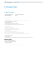
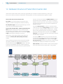
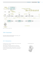
MAX310 BEESMART
SoLAR
MiCRo iNv RtER 260
USER MANUAL
2
USER MANUAL
Copyright
All rights with respect to this document, including applications for patent and registration of
other industrial property rights, are reserved. Unauthorized use, in particular reproduction or
making available to third parties, is prohibited.
Disclaimer of liability
this manual only describes the product and is not a warranty of performance or characteristic.
Contents of the manual has been reviewed against the hardware and software described. Any
liability can be accepted for any errors or omissions contained in the information given.
the installation, handling and use of Letrika micro inverters are beyond company control.
Letrika d.d. does not assume any responsibility for loss, damage, injury or expense resulting
from the improper installation, handling, use or maintenance.
this user manual only describes the product and is not a warranty of performance or
characteristic.
We reserve the right to change this document at any time without notice.
trademarks
Letrika Sol d.o.o. is registered trademarks of the Letrika d.d.. All other brand or product names
mentioned in this document may be trademarks or registered trademarks of their respective
holders.
Who should read this manual
this manual is intended to be used during installation, commissioning and maintenance as a
reference for installers, system integrators and other qualified personnel with knowledge of local
standards and regulations. they should always follow local electrical safety and fire protection
guidelines. only technically qualified personnel should install or replace Letrika Micro inverters.
USER MANUAL
3
table of contents
1
Introduction
4
1.1
Main features
4
1.1.1
PV Power Plant with Letrika Solar Micro inverters 260
5
1.2
Hardware Structure of Solar Micro Inverter 260
6
2
Safety
8
2.1
Symbols legend used in this manual and/or equipment
8
2.2
Safety and general warnings
8
2.3
General installation safety guidelines
9
3
Installation procedure
10
3.1
Compatible PV modules
10
3.1.1
Landscape versus portrait panels placement
11
3.1.2
Mounting hardware compatibility
12
3.1.2.1
Al profle selection
12
3.1.2.2
3.1.2.3
Inverter fxing screws positions
Inverter cooling consideration
12
13
3.2
Connecting cables to micro inverter
14
3.3
Connecting micro inverter system to utility grid
14
3.3.1
Simple single phase connection with I.P.S. device
15
3.3.2
Single phase connection without I.P.S. interface to grid
15
3.3.3
Three phase connection
16
3.3.4
Trunk cable extension and cable end covering
17
4
Commissioning
18
4.1
Preliminary checks
18
4.2
Sequence of operations
18
5
Troubleshooting
19
5.1
List of errors in alarm list
19
6
Storage
22
7
Disposal
22
8
Maintenance
22
9
Registration and warranty
23
10
Appendix
23
10.1
Technical specifcation
23
10.2
Certifcate
24
10.3
Identifcation and oredring code
25
10.4
Dimensions
25
10.5
Compatible dc connector systems
26
10.6
Compatible AC connector system
26
10.6.1
Trunk cable data
26
10.6.2
Accessories
27
10.6.2.1
Waterproof cap
27
10.6.2.2
Cable end cap
28
10.6.2.3
Cable joiner
28
11
Contact
29
4
USER MANUAL
iNtRoDUCtioN
1 introduction
1.1 Main features
• Nominal Apparent Power
290 vA at power factor f 0,9
• Nominal Real Power
260W
• Nominal Reactive Power
260 vAr at 0,95
• Max. Reactive Power
260 vAr
• Great efficiency
96,1%
• Large voltage and power input range - corresponds to the majority of Pv modules
• Reactive power capability – wide range
• Dynamic power factor
• incorporated relay for safe grid disconnection
• Galvanic isolation of DC side from AC side with HF transformer
• Low ripple current
• 0.0 W standby consumption
• WMBUS standard wireless communication
• DC circuit is isolated and insulated from ground
• Quick installation
• Full power at ambient temperature 65°C
• Die cast aluminum enclosure with completely potted electronics
• iP 67 – dust tight, no ingress of dust; immersion in water up to 1 m for 30 minutes
• Foiled capacitor, long life
• Design flexibility
• Letrika 50 years’ experience in automotive and heavy duty electronics and electro mechanics
Protection Function
• over and under voltage protection
• over and under frequency protection
• Anti-island protection
• Surge protection device (SPD) integrated
• Mains Monitoring Switching Device (MSD) integrated according to vDE 4105
iNtRoDUCtioN
USER MANUAL
1.2 Pv Power Plant with Letrika Solar Micro inverters 260
Pv power plant with Letrika Solar Micro inverters 260
consists of several components. Pv module directly
convert sunlight into DC electricity, micro inverters
change electrical current from DC to AC. Electricity is then
transferred via, trunk cables, junction boxes and main
distribution switch to the grid .
Each Pv module is directly connected to Letrika Solar Micro
inverter 260. Pv module and micro inverter is individual
power unit operating at maximum available power. the
operation of such power unit is independent and does not
affect the operation and performance of other power units.
Pv modules of different characteristic can be installed in
different position and orientation without interfering with
each other.
the operation of micro inverters can be controlled via Linux
based Gateway. Gateway communicates over wireless
WMBUS with Letrika Solar micro inverter 260 and over a
Wi-Fi or Ethernet with computer, smart phone or tablet.
We can monitor and analyze individual micro-inverters or
the whole power plant using browser on computer, smart
phone or tablet.
5
6
USER MANUAL
iNtRoDUCtioN
1.3 Hardware Structure of Solar Micro inverter 260
Solar Micro inverter converts direct current (DC) generated from a single Pv module to alternating current (AC).
Each micro inverter use Maximum Power Point tracking (MPPt) to maximize production of single Pv module.
Micro inverter has several functional units:
Input filter on DC side decouples Pv panel from high
frequency transients during DCDC converter switching.
DC side power supply of the primary (DCDC) logic is active
until minimum panel voltage is reached.
Primary DSP controller (16bit , 70MIPS, high performance
DSP) calibrates analog system, then starts to sample
Pv panel open circuit voltage. After Pv voltage reaches
sufficient voltage for reliable start of main flyback power
supply, secondary(AC) side logic is turned on.
At this point, power supply to both power sections is
activated, secondary DSP (32bit,60Mips controller) is
started.
After successful connection with primary DSP controller,
secondary controller will execute auto calibration and
after 10 seconds activate WMBUS RF module. this delay
is necessary for WMBUS module to stabilize operating
parameters and also to avoid unnecessary power oN/oFF
cycling in case of low irradiation. WMBUS module converts
inverter serial data into 868Mhz data stream according to
WMBUS standard. Data from micro inverter can be received
by Letrika data gateway or by any device compatible with
WMBUS standard.
the power DCDC converter is started in constant current
mode and high voltage. Energy storage capacitor is charged
up to minimum voltage needed for reliable start. voltage
level in energy storage capacitor changes with grid voltage,
optimizing switching losses on power section. Foiled
capacitors are use because they have lower aging compared
with electrolytic capacitors.
Concurrently DSP2 algorithms are synchronized with grid
and operating limits are checked. once DC voltage reaches
minimum level, AC inverter power stage is enabled, grid
disconnection relay (if present) is turned on and grid current
is gradually (according to standards limits) increased.
DCDC converter switches to MPPt tracker mode and begins
to track Pv panel maximum power point. A high speed
iNtRoDUCtioN
USER MANUAL
Differential mode filters are used for filtering 50 Hz current
from inverter carrier frequency,, .
Solar Micro inverter is in standby until there is insufficient
irradiance and a specific minimum voltage is present in
the inverter. the consumption in standby is 0W. the micro
inverter starts to fully operate when the sun begins to
supply energy and the voltage in Pv module reach 22vdc.
Common mode EMC filters are used for EMC interferences
filtering. tHD for
When the voltage drops below the minimum voltage value
(15vdc) feed-in mode ends and the inverter switches off.
processor with special algorithm is used to achieve high
efficiency and best possible harvest from sun.
Surge and Burst protections are used for protecting inverter
from lightening phenomena’s and grid over voltages. it
is strongly recommended to install external overvoltage
protection class ii on AC side, it is also condition for the
validity of Limited Warranty.
7
8
USER MANUAL
SAFEty
2 Safety
2.1 Symbols legend used in this manual and/or equipment
CAUTION
Generic danger - important safety information.
WARNING
Dangerous voltage. All precautions and
protections against high voltage electric
shock should be taken.
Connection to ground protection.
Note. Please read paragraph marked with
this icon carefully.
Hot SURFACE ! Danger of burns, do not
touch product.
Manual shall be consulted that must be
available for future use and not damaged.
2.2 Safety and general warnings
WARNING
Letrika inverters must be installed only by
technically qualifed personal.
WARNING
All electrical installations must be performed
in accordance with local and national electrical
standards and codes.
CAUtioN
in case of fault on Pv installation with Letrika
micro inverters, do not attempt disconnect Pv
or grid cables from inverters or junction boxes
until qualifed personal checks the installation.
Hot
SURFACE
Metal surface of Letrika micro inverters can reach
more than 70 degrees in operation. to reduce
risk of burns do not touch the inverter while in
operation. After switching of micro inverter wait
at least 10 minutes before touching it.
WARNiNG
Do not connect wet connectors. Connectors must
be dry before any attempt to connect them.
WARNiNG
Do not cut, bend or modify original connectors
and/or cables supplied with inverters.
CAUtioN
Lightning protection must be placed on each
inverters branch. Avoid wiring loops or rings.
Keep cable paths short as possible.
if required by local standards, AC wiring must
be additionally protected with RCDs and Earth
Fault Monitors where required.
CAUtioN
Before starting inverters for frst time, inspect
the wiring, measure isolation resistance between Pv+,Pv- and protective ground.
CAUtioN
Micro inverters should be mounted on
aluminum frame holding the Pv modules.
Preferably on upper side to avoid prolonged
submersion of inverters into water or snow. Do
not left inverters unfxed on the roof.
WARNiNG
WARNiNG
inverter and all metal components must be
grounded according to local standards.
WARNiNG
inverter Pv side is galvanically separated from
dangerous voltages; however do not attempt
to disconnect PC cables from inverter during
operation.
WARNiNG
Always mount grid disconnection switch between micro inverter installation and grid.
WARNiNG
there are no user serviceable parts inside
Letrika micro inverter. it is strictly forbidden
any intervention on micro inverter internal
structure.
SAFEty
USER MANUAL
2.3 General installation safety guidelines
the installation must be wired according to local regulations
and standards where inverters are mounted.
Follow local guidelines for grid monitoring devices and other
safety devices to be located between inverters and grid.
CAUTION
Grounding of all metal parts of the construction is the responsibility of installer.
WARNING
Micro inverters generates power from more
than one source
WARNiNG
When micro inverter is connected to Pv
module and exposed to light, dangerous
voltages may appear on output in case of
malfunction.
WARNiNG
WARNiNG
inverters with damaged enclosure or wiring
must not be repaired and must be returned
to producer
it is forbidden to connect DC input of micro
inverter to the battery or any other DC
power supply. Solar micro inverter can be
connected only to Pv module.
WARNiNG
Use only originally supplied cables. Use
original end cap from ALtW cable producer
to ensure iP67 protection on whole cable
trunk.
CAUtioN
Connect circuit breaker with overcurrent
protection according to Pv plant power and
local standards.
CAUtioN
Always fx cables to the frame. Do not allow
Pv and grid cables to foat free.
CAUtioN
if equipment is not used as specifed in
this manual and other Letrika documents,
protection provided by the equipment may
be impaired.
9
10
USER MANUAL
iNStALLAtioN PRoCEDURE
3 installation procedure
During installation it is a good idea to follow a check list of
operations. We will describe general approach that allows
installation of the inverters that is easy to manage and
maintain.
3.1 Compatible Pv modules
Letrika micro inverters are compatible with monocrystalline
and polycrystalline panels with 60 and 72 cells per panel.
inverter power is not entirely used, efficiency is lower and
this affect the production of electricity.
thin film panels are normally not suitable because of
higher panel dc voltage incompatible with micro inverter
input range. However some thin film panels with output
voltage of approx. 50v can still be used with Letrika micro
inverters. thin film modules have a risk of tCo corrosion.
Consult the producer of thin film panels how to ground
the positive or negative terminal of the Pv module. Letrika
Solar micro inverter 260 allows using the positive or
negative grounding.
When higher power Pv modules are used, consider that the
micro inverter can deliver approx. 300W of AC power for
approx. 20 minutes at 30°C.
Pv modules from 220Wp up to 310Wp can be connected
to the inverter. Using lower power Pv modules, the micro
During selection of Pv modules power consider also
average and peak operating ambient temperature. From
the point of view of micro inverter performances, there
is no derating in performances until 65 degrees ambient
temperature is reached.
open circuit voltages (Uoc) and short circuit currents (isc)
of Pv modules shouldn’t exceed the declared values in
technical specification.
iNStALLAtioN PRoCEDURE
3.1.1 Landscape versus portrait panels placement
Portrait or landscape layout could be used when installing
more Pv panels.
Layout of Pv panels will affect the choice of trunk cable.
if the layout is portrait the distance between the
connections on trunk cable are every 1,05 m.
if the layout is landscape the distance between the AC
connections on trunk cable are every 1,70 m or 2,00 m.
Landscape panels orientation
Portrait panels orientation
USER MANUAL
11
12
USER MANUAL
iNStALLAtioN PRoCEDURE
3.1.2 Mounting hardware compatibility
Letrika Solar micro inverter is designed to be compatible
with most standard Al frames. During frame selection few
important thing must be observed.
3.1.2.1 Al profle selection
Al profile must have a t shaped groove for M8 or M6 nut.
M8 screw inserted into t shaped groove. if screw is
inserted it is easier to place and fix the micro inverter.
Screws must be inserted before the frame is assembled,
since they can`t be moved across frame junctions.
if M8 or M6 nuts are inserted into profile care should be
taken during screw length selection, since long screws can
damage the AL profile or they cannot fix micro inverter
adequately.
Use M8 or M6 screws and nuts. Do not use smaller or larger
screws for fixing the micro inverter
Al profile width must match micro inverter fixing tab
length. there are several possibilities how to mount
the inverter on the profile each with advantages and
disadvantages.
3.1.2.2 inverter fxing screws positions
install the mounting screws (M8 x 16) on the body of
the supporting structure at intervals of 130 mm and
installation of the casing by tightening the bolts to torque
Nm 9. Do not over torque.
iNStALLAtioN PRoCEDURE
USER MANUAL
3.1.2.3 inverter cooling consideration
For proper inverter operation and full performance
delivery some mounting guidelines must be observed.
Although micro inverter does not need any forced
ventilation and is cooled by natural heat exchange
with surrounding air, it still need some air around its
aluminum enclosure to cool efficiently.
We strongly suggest to place micro inverter at least
15mm bellow the panel surface and to leave at least
20mm between inverter and underneath surface to
avoid panel heating and micro inverter overheating.
Micro inverter can be positioned above or below
supporting Al frame, as indicated on drawings
bellow. Placing micro inverter on bottom side of Al
support, decrease heat transfer from micro inverter
to solar panel, increasing efficiency on high ambient
temperatures.
Recommended mounting for optimal heat dissipation (micro inverter on
bottom side of supporting frame)
Mount micro inverter in locations, which are out of
direct sunlight.
We do not recommend mounting micro inverter directly
between panel and roof surface since air irculation is not
guaranteed. Efficiency of the system will be decreased
and the micro inverter and
the panel can be overheated if mounted like shown on
bellow drawing.
if micro inverters are mounted as showed above,
warranty period is voided.
Forbidden micro inverter mounting
Recommended mounting for optimal heat dissipation (micro inverter on
top of supporting frame
13
14
USER MANUAL
iNStALLAtioN PRoCEDURE
it is a good practice to mount inverter in the middle
of the panel width, regardless if the panel is placed in
portrait or landscape position.
Horizontal placement of the inverter
3.2 Connecting cables to micro inverter
Connecting cables to micro inverter is simple. Just connect
DC cables connectors into matched panel DC connectors
coming from panel junction box. Push connectors together
until they latch with audible CLiCK.
Some DC connectors are marked with + and – engraved on
plastic. Polarity is valid for panel side. on micro inverter,
we placed two additional colored signs on DC wires. BLUE
for DC- and RED for DC+ wire. Please take care about right
polarity while connecting inverters. Before connecting the
inverter measure voltage polarity on Pv module.
insert AC connector from inverter into t junction connector
on the cable. Again, push connectors until audible CLiCK is
heard and connector is latched.
Connecting cables to micro inverter
3.3 Connecting micro inverter system to utility grid
Micro inverter must be connected to the utility grid in
accordance with local standards and permissions.
Letrika Solar micro inverter 260 has built in interface
protection system (iPS) according to vDE 4105. All frequency,
voltage and anti-islanding protections are embedded inside
micro inverter. Also power factor, voltage control functions are
built-in. inside micro inverter is a relay with double contacts
to physically disconnect micro inverter from the grid. External
iPS must be connected between micro inverters and grid if
required by local standards and permission.
We strongly suggest to mount surge protection devices into
roof junction box or better, to use surge protector systems
that are mounted in same housing as micro inverter and can
be connected to standard ALtW Pt 3 wire system allowing
placement of surge protections also in between micro
inverters improving surge immunity.
Please contact Letrika for details on surge protection devices.
iNStALLAtioN PRoCEDURE
USER MANUAL
3.3.1 Simple single phase connection with i.P.S. device
inverters are simply connected to ALtW Pt-3 trunk cable.
See table 1 for maximum allowed number n of micro
inverters per trunk.
i.P.S. device may vary from country to country, please
check with local distributor company.
Not used t junctions on trunk cable must be covered with
watertight cap.
Single phase system with i.P.S
3.3.2 Single phase connection without i.P.S. interface to grid
Since Letrika micro inverters have built in i.P.S. according
to vDE 4105 standard with incorporated disconnection
relay, they can be used, if a local standard permits,
Single phase connection without i.P.S inteface
without additional i.P.S device interfacing to grid, only grid
disconnection switch must be used.
15
16
USER MANUAL
iNStALLAtioN PRoCEDURE
3.3.3 three phase connection
Micro inverters can be connected also on three phase grid
system. Although they can operate even in event of one or
two phase failure, it is generally not recommended, and in
some countries also forbidden to operate with one or more
phases interrupted or in short circuit. it is recommended to
use protection against unbalanced load.
iNStALLAtioN PRoCEDURE
USER MANUAL
3.3.4 trunk cable extension and cable end covering
Guidelines for trunk cable extension and cable end covering
are showed below. it’s not allowed to extend the trunk cable
above maximum number of t junctions specified in table 1.
trunk extension is normally necessary when panels and micro
inverters are mounted on different places on the roof, making
difficult to connect them only by using trunk cable.
Always use original cable joiner CX-04BCM32-7002 to ensure
trunk cable join point water tightness.
Figure 12 trunk cable extension and cable ending
insert CAP-WtCASMA2 on exposed cable end since original
water tight cap ensure iP67 protection of exposed trunk
cable end.
if trunk extension is done by using customer supplied cable,
please note that the cable must be Uv reinforced cable with
cold bending 90 degrees at -40°, 90° maximum temperature.
17
18
USER MANUAL
CoMMiSSioNiNG
4 Commissioning
Commissioning should be done by technically qualified personal.
Connecting cable output AC and DC voltage input cables
should be carried out in accordance with the manufacturer's
instructions (AMPHENoL).
4.1 Preliminary checks
• Check the data on micro inverter and verify compliance
of these data with grid data
• Check the position of all connection cables and the
tightness of all nuts and terminals
• Peel the label with Serial number and attach it to the
matrix in the same order as they are installed.
• Check the micro inverter is firmly mounted
• When conducting the checks, ensure that the main AC
disconnector switch (downstream from the system) and
any other possible isolation switches are switched off
position
• Ensure that all conductors and protective grounding
points are connected
4.2 Sequence of operations
• Switch on the main AC disconnector switch
(downstream from the system) and any other possible
isolation switches
• Proceed with configuration of Gateway. Details are
described in Gateway User Manual.
• Ensure that all electrical safeguards have been correctly
installed
• Ensure that the complete system has been checked,
tested and approved in accordance with the local
standards and codes
tRoUBLESHootiNG
USER MANUAL
5 troubleshooting
the operating state of the micro inverters can be
monitored on the Gateway LCD. LCD shows the status of
the plant on default view. in normal operation the status
is »working«, it means that everything is oK.
if an internal or external fault occurred, the LCD displays
status: »alarm« . Gateway stores errors in alarm list, which
can be at any time retrieved from it with web application.
the inverter will not feed the grid while the alarm on LCD is
present.
only technically qualified personal may perform work on
electrical installation.
Example of Alarm history from web application
5.1 List of errors in alarm list
1
ERR_OVER_
CURRENT_SW
over current on AC side is detected by software.
Possible cause is short circuit on grid lines or sudden voltage drop on grid lines.
Proposed action:
• Check connecting lines
• Check surge protections on lines
• Check external power capacitors banks for power factor corrections
• Scan grid voltage for deeps
2
ERR_OVER_
CURRENT_HW
over current is detected by hardware. Possible cause is very high short circuit current, very
deep voltage transients or high voltage surge spikes.
Proposed action:
• Check connecting lines
• Check surge protections on lines
• Check external power capacitors banks for power factor corrections
• Scan grid voltage for deeps
3
ERR_OVER_
VOLTAGE
this signal is active if DC high voltage too high.
Possible cause for DC high voltage to rise above safety limits is very unstable grid with
changing shadows on Pv module.
Proposed action:
High voltage spikes from grid are transferred to DC high voltage capacitors
Check grid voltage and transients
19
USER MANUAL
20
tRoUBLESHootiNG
4
ERR_UNDER_
VOLTAGE
DC high voltage is too low. During operation on high output power, deep shadowing occurred.
it is possible that DC voltage drops too low and it is not possible to push the current into the
grid.
Proposed action:
• Check DC connectors
• if under voltage is repeated on same panels, check all connections
5
ERR_ADC
internal circuit problem
internal circuit calibration failed
Proposed action:
• Replace inverter
6
ERR_PANEL_
VOLTAGE_LOW
Panel voltage is too low to operate. inverter detected too low voltage on Pv panel to ensure
correct energy transfer to secondary side.
Proposed action:
• Wait panel voltage to rise up, if this error insist under heavy sun, then check panel voltage
or replace inverter
7
ERR_OVER_
TEMPERATURE_
CONTROLLER
DC or AC side power section over temperature.
temperature on DC or AC power section reached maximum allowed temperature, approx. 90
degrees centigrade.
Proposed action:
• check ambient temperature is lower then 65 degrees
• check inverter exposure to direct sun light
• air is not circulating across inverter enclosure
8
ERR_PARAMETERS_
CORRUPTED
internal Country and other parameters corrupted.
internal FRAM memory corrupted.
Proposed action:
• Replace inverter
9
ERR_ADC_OFFSET_
ERROR
internal ADC ofset to high.
internal analog to digital converter ofset is out of adjustable range.
Proposed action:
• Replace inverter
10
ERR_INTERPROC_COM
CRC error in interprocessor communication.
An CRC error occurred between both DSP controllers on inverter.
Proposed action:
• Error should reset automatically after some time, if not, replace inverter
11
ERR_GRID_VOLTAGE
Grid voltage to high or too low.
Grid voltage is out of limits, according to country standard.
Proposed action:
• too much inverters on grid line
• installation close to grid low voltage transformer
• Grid without power factor correction capability tRoUBLESHootiNG
USER MANUAL
12
ERR_GRID_FREQUENCY
Grid frequency out of range.
Grid frequency is out of range prescribed in standard for given country.
Proposed action:
• verify grid frequency, if condition insist or this error is noticed on all inverters in installation,
• Check for locally installed generators, other solar installations or wind turbines, which can
cause frequency slipping
• Check for islanding operation of the inverters
13
ERR_SYSTEM_SW
Firmware CRC error.
inverter frmware auto test detected frmware CRC error in one of DSP controllers.
Proposed action:
• Replace inverter
14
ERR_COMMUNICATION_
TIMEOUT
No communication between DSP processors.
Main DSP processor can not see any communication from DCDC DSP controller.
Proposed action:
• Wait inverter to reset during the night. if condition persist, replace inverter
15
ERR_GRID_DISCONNECTED
No grid
Grid is disconnected or internal PLL can not catch any valid sinusoidal signal
Proposed action:
• No grid connected, very distorted grid current, very low grid voltage.
16
ERR_IGRID_DC_COMPONENT
DC current injected to grid is too high.
internal circuit detected too high DC current injected to grid.
if condition is rare, than some transients can cause inverter to trigger this error.
Proposed action:
• if condition repeats continuously, then check other sources on the grid that might cause
DC current in it, restart inverter, or if condition persists, replace inverter.
17
ERR_FAST_LOOP_INT
18
ERR_SLOW_LOOP_INT
internal frmware errors, safety shut down.
Proposed action:
• if problem persist, replace inverter
19
ERR_STATE_MACHINE
21
22
USER MANUAL
6 Storage
the equipment must be stored in suitable warehouses. After
long period of storage clean accurately micro inverter before
installing it. Check the contacts that are not oxidized.
7 Disposal
the owner of micro inverter must dispose it in accordance
with local directives and regulations. it is forbidden to
deposit electrical and electronic equipment as municipal
waste.
the complete procedure after lifetime should comply with
Directive 2012/19/EU of the European Parliament and of
the Council of 4 July 2012 on waste electrical and electronic
equipment (WEEE).
Micro inverter can be send back to manufacturer or provider
for disposal. Delivery costs in this case are covered by
sender or owner.
Component and material identification:
• Housing Aluminum
• Filler - PU
• Gaskets and seals Rubber / tefon / viton
• Electrical cables Copper / Rubber
• Conduits Polyethylene / Nylon
• HF transformer - Fe
8 Maintenance
Micro inverter should be inspected and cleaned if necessary
at least once a year. it is recommended to regularly check
for signs of damage. Regularly check for dust, dirt and
moisture. if necessary clean the device. For cleaning use
compressed air, a vacuum cleaner or special brushes.
Although original cable system used on Letrika micro
inverters is state of the art with extra-long live, resistant
to water, Uv, temperature, oil and moisture, we suggest
to check connections between inverters every year. Special
attention should be placed on junction boxes where most
of bad connections and problems can occur.
USER MANUAL
9 Registration and warranty
the standard product warranty for Solar Micro inverter 260
and is 5 years. it is possible to extend the system warranty
to 7 years by registering to Letrika Sol at www.letrikasol.
sol. By registering also Limited warranty for 25 years
becomes valid.
All warranty conditions are available on the web side.
10 Appendix
10.1 technical specifcation
DC OPERATING PARAMETERS
Maximum DC input power
310 Wp
Maximum DC input voltage
60 V
MPPT voltage range
22-55 V
Operating range
15-60 V
Start-up DC input voltage
21 V
Maximum DC input current
10.5 A
Short Circuit DC input current
12 A
Panel ripple current
50m A
DC connection system
Amphenol MC4
AC OPERATING PARAMETERS
Nominal apparent power
290 VA
Nominal real power
260 W
Nominal reactive power
128 VAr at
cosϕ=0,9
Grid voltage range
185-270 V
1ph
Maximum AC current
1.26 A
Nominal frequency
50 Hz
47.5..50.5Hz
Peak Power 15 min
290 W
Power factor range
0.8-1
limited with ambient temperature
• Dynamic with power
• Dynamic with voltage-frequency
• Fixed between 0.8 to 1
Maximum overcurrent protection
2A
Inverters per trunk
20
AC connection system
Amphenol LTW SPS 03
connection system UL & VDE approved
23
USER MANUAL
24
APPENDiX
AC PROTECTION
Anti-Islanding
According to local standard
Overcurrent
2A
PERFORMANCE
Peak Efciency
96,1%
CEC Efciency
95.5%
EURO Efciency
95,3%
MPPT tracking Efciency
99.9%
Stand-by consumption
0W
ENVIRONMENTAL
Ambient temperature
-40 … +65 °C
Relative humidity
0..100%
Ingress Protection Rating
IP 67
Maximum altitude
2000m
Noise
30db(A)@1m
Cooling
Mounting brackets
Natural
209x243x38mm with
brackets
M8x16, distance 130 mm
Weight
2200g
Housing
Die casted aluminium
Dimensions
Communication
WMBUS
Lifetime expectancy
25 years
Limited Warranty
25 years
VDE 4105
CEI 0-21
EN 62109-1
EN 62109-2
EN 61000-6-3
HF transformer
Standards
Isolation Level
Safety class
Overvoltage Category
I
II (input DC)
III (input AC)
10.2 Certifcate
Solar Micro inverter 260 was tested in accreditation
laboratory according to international standards.
Certificate can be downloaded at: www.letrikasol.si
no derating
EN 13757-1 … 5
reinforced insulation
APPENDiX
10.3 identifcation and oredring code
ordering code:
AEi-1101-S-C70-P260-F50-U230- vDE-ALtW-G
Where:
AEi
1101
S
C70
P260
F50
U230
vDE
ALtW
G
Family name
Family member
input type – S is for solar photovoltaic DC input
Cells on Pv panel
output power 260W
output frequency 50Hz
output voltage 230vac
Settings according to standard vDE4105,
other CEi for CEi-0-021, G83, CSL
type of AC connector
for grid connection
10.4 Dimensions
USER MANUAL
25
26
USER MANUAL
APPENDiX
10.5 Compatible dc connector systems
Pv connectors are compatible with MC4 standard
connectors. on request, other types of connectors are
available. Amphenol LtW H4 connection system
10.6 Compatible AC connector system
Amphenol ALtW connection system is composed from one
single AC cable from micro inverter and trunk cable where
up to 20 inverters can be connected. Both AC cable and
the trunk are equipped with locking connectors that can
be separated by using special unlock key and they are iP67
rated.
Reliability, current capability and lifetime are considerably
increased by using direct trunk connector and cable
molding technology and by using insulation displacement
main cable contacting, without interruption of main cable.
two types of cables are available UL and vDE approved,
while connectors are always the same. Cables and plastic
materials are chosen and tested under most harsh
conditions imaginable and they are Uv, salt fog, oil,
temperature and bending resistant.
Please, do not cut, disassemble or modify connectors
and cables. Do not use matching products that are not
produced by ALtW since cable performances can be altered
and possible dangerous situations may occur.
in addition to two basic connectors, some more additional
connectors are available for cable ending or joining.
10.6.1 trunk cable data
very important is to choose the right trunk cable pitch,
depending on panel dimensions and orientation.
Consider that also maximum number of micro inverters per
trunk change with connectors pitch. See bellow tables and
drawings for details.
Trunk cable ID:
Panels orientation:
Max. number of T connectors on trunk :
Pt-3-4A-105-00-020-EU
Portrait
20
Pt-3-4A-170-00-018-EU
Landscape-170 cm panels
18
Pt-3-4A-205-00-017-EU
Landscape-205 cm panels
17
Pt-3-4A-105-00-020-UL
Portrait
20
table 1 trunk cable types and maximum number of micro inverters per trunk
APPENDiX
USER MANUAL
Figure 13 ALtW trunk cable drawing
10.6.2 Accessories
For easier waterproof cable elongation end ending, some
additional accessories are available:
10.6.2.1 Waterproof cap
Waterproof cap is used as watertight cover on unconnected
t junctions on trunk cable.
White plastic cap originally attached on t junctions iS
Not watertight; it is there only for dust and mechanical
protection during transport and installation. in case some t
junctions are left unconnected, use this cap to water tight
the junction.
CAP-WSMMFLA-P1
27
28
USER MANUAL
APPENDiX
10.6.2.2 Cable end cap
Cable end cap is used for watertight closing of exposed
cable end. Simply push the cable into end cap, the wires
inside the cable are automatically separated to avoid
short circuits and tight the nut.
CAP-WtCASMA2
Always use original trunk cable with this end cap.
Waterproofness is not guaranteed with other cable types
10.6.2.3 Cable joiner
Cable joiner is used to join two ends of trunk cable. it is
simple to use and after assembled, iP67 protected cable
joining tool.
to assemble two cable ends together, please consult
bellow picture
CX-04BCM32-7002
CoNtACt
USER MANUAL
11 Contact
Letrika Sol d.d. is a joint venture between Cosylab d.d. and Letrika d.d.
Headquarters
Letrika Sol d.o.o.
Vrtobenjska 64
5290 Šempeter pri gorici
Slovenia
E: [email protected]
www.letrikasol.com
t: 00386 5 339 4262
SMS Metering Ltd/SolarCorner
41 London Road, Castle Court, Reigate RH2 9RJ
TEL: 0845 604 7244
E-mail: [email protected]
Web: www.smsmetering.co.uk
29