1
Rack-mounted Modem Shelf
USER'S MANUAL
V1.6
07008-00014
2004/03/24
CHAPTER 1
INTRODUCTION
CONTENT
1.1 Modem Shelf and NMC
1.2 Rack-mounted Modem and NTU
Introduction
1-1
CHAPTER 1 Introduction
1.1 Modem Shelf and NMC
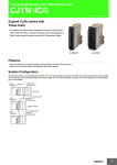
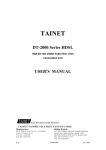
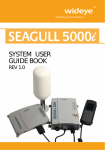
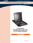
The DCE rack-mounted modem shelf, as illustrated below, is desi ged nfor
centralized networks which need a lot of modems.
RS-485 to NMS
........
DCE
and/or
RS-232 to NMS
........
Dual Power Supplies
built in the Modem Shelf
Network Management Controller (NMC)
DCE Rack-mounted Modems or NTUs
Fig. 1-1 DCE Rack-Munt Modem
The modem shelf RM32MUI or RM16MUI employs the standard rack with
5RU (about 255 mm) which accommodates up to 16 concentrated modem cards. In
addition, the Network Management Controller NMC16 used with RM32MUI or
RM16MUI supports two levels of network management system (NMS).
The users may choose either or both to work with in order to meet various requirements.
The first (basic) level network management only needs a rack. In this condition, the
control unit is responsible for the operation of the network management system. It can
setup, control, and test with any specific modem card in the same shelf. In addition, it
continuously scans all the modem cards and reports any erroneous and abnormal
conditions such as signal quality degradation which exceeds a predetermined threshold.
You may observe this kind of condition by audible alarm and visible crystal display
(LCD) by operating front panel keys. Consequently, troubleshooting procedure might be
determined.
In the case that there are only a few modem cards, this level of network management
will meet the requirements. Whereas, if there are a lot of modem cards or if the modems
and the people being on duty are not collocated, the higher level network management
system is required.
In the second level network management system, you may connect several modem racks
to a network master controller which is composed of a computer and a control unit in
"daisy chain" structure. By employing this structure, you may construct a larger network
management system which may manage up to 130,000 modems in this system which
will satisfy the needs of most large-size networks.
For more details about this level of NMS, please refer to the User's Manual of DCE
MANAGER for Windows.
1-2
Introduction
1.2 Rack-mounted Modem and NTU
The modem shelf RM32MUI can accommodates up to 16 concentrated V3600UI-DUAL (two fullfeatured V.34 modems on a single card), DT-128N NTU and T-336NDx modem cards.
Also, the modem shelf RM16MUI can accommodate up to 16
concentrated DCE-series modem cards
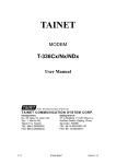
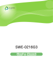
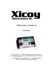
1.2.1 The V3600UI-DUALRM Modem Front Panel
The shelf RM32MUI can accommodates up to 16 concentrated V.3600UI-DUAL modem cards (two
full-featured V.34 modems on a single card). The front panel of the V.3600UI modem
card is illustrated below:
1. Front Panel Switch : One touch switch VO/DA
Voice and data switch,used in dial up applications.
Whereas in the leased line applications, it functions
as "reconnect".
V.34 Modem (N.o 1)
SEL Indicator
LED Indicators
2. SEL Indicators : One red LED indicates this modem
card is being selected.
3. LED Indicators : 10 LEDs on front panel.
DTR - DTR signal indicator .
DSR
- DSR signal indicator.
RTS
- RTS signal indicator.
CTS
- CTS signal indicator.
TXD - Transmit data indicator.
DCD - Receive carrier indicator.
RXD - Receive data indicator.
OH
- Off-Hook indicator.
TST
- Test mode indicator.
SCAN - Being scanned by control unit.
Data/Voice Switch
SEL Indicator
LED Indicators
Data/Voice Switch
T-288ND
V.34 Modem (N.o 2)
Fig. 1-2 The V3600UI-DUAL
Modem Front View
Introduction
1-3
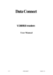
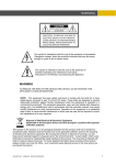
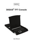
1.2.2 The NTU Front Panel
The shelf RM32MUI can accommodates up to 16 concentrated NTU cards. The
front panel of the NTU card is illustrated below:
1. Front Panel Switch : One RESET touch switch.
2. SEL Indicators : One red LED indicates this NTU
card is being selected.
3. LED Indicators : 10 LEDs on front panel.
DTR - DTR signal indicator .
DSR
- DSR signal indicator.
RTS
- RTS signal indicator.
CTS
- CTS signal indicator.
TXD - Transmit data indicator.
DCD - Receive carrier indicator.
RXD - Receive data indicator.
ACT - Connection indicator.
TST
- Test mode indicator.
SCAN - Being scanned by control unit.
SEL Indicator
LED Indicators
Reset Switch
Fig. 1-3 The
NTU Front View
CHAPTER 1
INTRODUCTION
CONTENT
1.1 Modem Shelf and NMC
1.2 Rack-mounted Modem and NTU
Introduction
1-1
CHAPTER 1 Introduction
1.1 Modem Shelf and NMC
The DCE rack-mounted modem shelf, as illustrated below, is desi ged nfor
centralized networks which need a lot of modems.
RS-485 to NMS
........
DCE
and/or
RS-232 to NMS
........
Dual Power Supplies
built in the Modem Shelf
Network Management Controller (NMC)
DCE Rack-mounted Modems or NTUs
Fig. 1-1 DCE Rack-Munt Modem
The modem shelf RM32MUI or RM16MUI employs the standard rack with
5RU (about 255 mm) which accommodates up to 16 concentrated modem cards. In
addition, the Network Management Controller NMC16 used with RM32MUI or
RM16MUI supports two levels of network management system (NMS).
The users may choose either or both to work with in order to meet various requirements.
The first (basic) level network management only needs a rack. In this condition, the
control unit is responsible for the operation of the network management system. It can
setup, control, and test with any specific modem card in the same shelf. In addition, it
continuously scans all the modem cards and reports any erroneous and abnormal
conditions such as signal quality degradation which exceeds a predetermined threshold.
You may observe this kind of condition by audible alarm and visible crystal display
(LCD) by operating front panel keys. Consequently, troubleshooting procedure might be
determined.
In the case that there are only a few modem cards, this level of network management
will meet the requirements. Whereas, if there are a lot of modem cards or if the modems
and the people being on duty are not collocated, the higher level network management
system is required.
In the second level network management system, you may connect several modem racks
to a network master controller which is composed of a computer and a control unit in
"daisy chain" structure. By employing this structure, you may construct a larger network
management system which may manage up to 130,000 modems in this system which
will satisfy the needs of most large-size networks.
For more details about this level of NMS, please refer to the User's Manual of DCE
MANAGER for Windows.
1-2
Introduction
1.2 Rack-mounted Modem and NTU
The modem shelf RM32MUI can accommodates up to 16 concentrated V3600UI-DUAL (two fullfeatured V.34 modems on a single card), DT-128N NTU and T-336NDx modem cards.
Also, the modem shelf RM16MUI can accommodate up to 16
concentrated DCE-series modem cards
1.2.1 The V3600UI-DUALRM Modem Front Panel
The shelf RM32MUI can accommodates up to 16 concentrated V.3600UI-DUAL modem cards (two
full-featured V.34 modems on a single card). The front panel of the V.3600UI modem
card is illustrated below:
1. Front Panel Switch : One touch switch VO/DA
Voice and data switch,used in dial up applications.
Whereas in the leased line applications, it functions
as "reconnect".
V.34 Modem (N.o 1)
SEL Indicator
LED Indicators
2. SEL Indicators : One red LED indicates this modem
card is being selected.
3. LED Indicators : 10 LEDs on front panel.
DTR - DTR signal indicator .
DSR
- DSR signal indicator.
RTS
- RTS signal indicator.
CTS
- CTS signal indicator.
TXD - Transmit data indicator.
DCD - Receive carrier indicator.
RXD - Receive data indicator.
OH
- Off-Hook indicator.
TST
- Test mode indicator.
SCAN - Being scanned by control unit.
Data/Voice Switch
SEL Indicator
LED Indicators
Data/Voice Switch
T-288ND
V.34 Modem (N.o 2)
Fig. 1-2 The V3600UI-DUAL
Modem Front View
Introduction
1-3
1.2.2 The NTU Front Panel
The shelf RM32MUI can accommodates up to 16 concentrated NTU cards. The
front panel of the NTU card is illustrated below:
1. Front Panel Switch : One RESET touch switch.
2. SEL Indicators : One red LED indicates this NTU
card is being selected.
3. LED Indicators : 10 LEDs on front panel.
DTR - DTR signal indicator .
DSR
- DSR signal indicator.
RTS
- RTS signal indicator.
CTS
- CTS signal indicator.
TXD - Transmit data indicator.
DCD - Receive carrier indicator.
RXD - Receive data indicator.
ACT - Connection indicator.
TST
- Test mode indicator.
SCAN - Being scanned by control unit.
SEL Indicator
LED Indicators
Reset Switch
Fig. 1-3 The
NTU Front View
1-4
Introduction
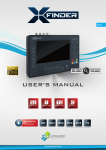
1.2.3 The V3600UI-RM Modem Front Panel
The shelf RM32MUI can accommodates up to 16 concentrated V3600UI-RM modem cards
(two full-featured V.34 modems on a single card). The front panel of the V.3600UI=RM
modem card is illustrated below:
1. Front Panel Switch : One touch switch VO/DA
Voice and data switch,used in dial up applications.
Whereas in the leased line applications, it functions
as "reconnect".
SEL Indicator
2. SEL Indicators : One red LED indicates this NTU
card is being selected.
LED Indicators
3. LED Indicators : 10 LEDs on front panel.
DTR - DTR signal indicator .
DSR
- DSR signal indicator.
RTS
- RTS signal indicator.
CTS
- CTS signal indicator.
TXD - Transmit data indicator.
DCD - Receive carrier indicator.
RXD - Receive data indicator.
OH
- Off-Hook indicator.
TST
- Test mode indicator.
SCAN - Being scanned by control unit.
Data/Voice Switch
SEL Indicator
LED Indicators
Data/Voice Switch
Fig. 1-4 The V3600UI-RM
Modem Front View
Introduction
1-5
1.2.4 The DCE-series Modem Front Panel
1. Front Panel Switch : One touch switch
VO/DA Voice and data switch,used in dial up
applications. Whereas, it functions as
"reconnect" in leased line
applications.
SEL Indicato
2. SEL Indicators : One red LED indicates this
modem card is being selected.
LED Indicat
3. LED Indicators : 10 LEDs on front panel.
DTR - DTR signal indicator .
DSR
- DSR signal indicator.
RTS
- RTS signal indicator.
CTS
- CTS signal indicator.
TXD - Transmit data indicator.
DCD - Receive carrier indicator.
RXD - Receive data indicator.
OH
- Off hook indicator.
TST
- Test mode indicator.
SCAN - Being scanned by control unit.
AUX Jack
VO/DA Swit
Fig. 1-5 The DCE-Series
Modem Front View
4. Auxiliary Jack : This function well be only equipping for the T-1496N and
T-288NC, not provided by 3600UI-RM.
This is an 8-pin jack (RJ45 like). It provides you the ability to maintain lines
from just front panel as described below.
Table 1-1 The Pin Arrangement of AUX Jack
Pin No.
1
2
3
4
5
6
7
8
Color
Blue
Orange
Black
Red
Green
Yellow
Brown
White
Function
2W/4W-Tx
2W/4W-Tx
Not Used
Tip (Dial Line)
Ring (Dial Line)
Not Used
4W-Rx
4W-Rx
For more details about the operation of the DCE-series modem, please refer to the User's
Manual.
1-6
Introduction
1.3 Ordering Information
For TRS16 Shelf
Model
RM16MUI
NMC
Description
Part No.
19" width rack for up to 16 modem cards 000041-0012
(16ports)
NMS Control unit used with TRS16
000012-0018
PW-130AC
90 ~ 265 VAC power unit for rack
000012-0011
PW-130DC
-36 ~ -72 VDC power unit for rack
000012-0012
FAN - 12
Cooling fan set
000012-0015
DCE Manager
for Windows
V.34/V.32 network management system
000042-0005
For TRS32 Shelf
Model
RM32MUI
NMC
Description
Part No.
19" width rack for up to 16 modem cards 000053-0004
(32ports)
NMS Control unit used with TRS32
000055-0002
PW-132A
90 ~ 265 VAC power unit for rack
000057-0001
PW-132D
-36 ~ -72 VDC power unit for rack
000057-0002
CA50
50 pin cable with standard centronic
connector for TRS32
000053-0003
TB32
The rear panel terminal block module board
of the TRS32 for 2/4-wire Leased and Dial
line connection
000053-0002
DCE Manager
for Windows
V.34/V.32 network management system
000042-0005
CHAPTER 2
INSTALLATION
CONTENT
2.1 RM32MUI Rear Panel
2.2 RM16MUI and RM16MUI-B Rear Panel
2.3 RM16MUI-A Rear Panel
Installation
2-1
CHAPTER 2 Installation
The t can be fit into a 19inch standard rack with 5RU (about 255 mm) high. You may start to connect wired after
proper placing the racks. At the first, you should pay particular attention to the
connection of the power core. The voltage 90 ~ 265VAC or -36 ~ -72VDC even single
or dual power can be selected in the different power supply cards.
2.1 RM32MUI Rear Panel
The shelf is designed for centralized networks which accommodates up to
sixteen (16) concentrated modem cards. The connections located on the rear
panel are illustrated as below:
Fig. 2-1 RM32MUI Rear Panel
1. 115/230 VAC:AC Input 115/230 ± 10% VAC.
2. -48V & 0V:DC Input -36 ~ -72 VDC.
3. GND & -12:Provide DC Source -12 VDC for cooling fan model FAN-12.
4. Ext. Alarm:A relay connection in conjunction with external alarm system.
5. NMS RS-485:RS-485 connector for NMS.
6. NMS RS-232:RS-232 connector for NMS.
7. NORMAL/TERMINATION:Terminator Switch for NMS RS-485 interface.
8. PG & SG:Protective Ground and Signal Ground.
9. DTE 1 ~ DTE 32:RS-232 Interface for PC or Terminal connection.
10. CON 1 ~ CON 4:50-pin centronic connector for telephone line connection.
11. NMS Jacks:Two RJ11 Jacks in conjunction with NMS RS-485 PREV
terminals, the pin arrangement is illustrated as Figure 2-5.
2-2
Installation
2.2 RM16MUI and RM16MUI-B Rear Panel
The RM16MUI shelf is designed for centralized networks which accommodates up
to sixteen (16) concentrated modem cards. The differences between RM16MUI and
RM16MUI-B are NMS jack and GND & -12V connectors. The connections located on the
rear panels are illustrated as below:
Fig. 2-2 RM16MUI Rear Panel
Fig. 2-3 RM16MUI-B Rear Panel
1. 115/230 VAC AUTO RANGE: AC Input 90 ~ 265 VAC.
2. -48V & 0V: DC Input -36 ~ -72 VDC.
3. GND & -12V: Provide DC Source -12 VDC for cooling fan model FAN-12.
4. Ext. Alarm: A relay connection in conjunction with external alarm system.
5. NMS RS-485: RS-485 connector for NMS.
6. NMS RS-232: RS-232 connector for NMS.
7. NORMAL/TERMINATION: Terminator Switch for NMS RS-485 interface.
8. PG & SG: Protective Ground and Signal Ground.
9. DTE 1 ~ DTE 16: RS-232 Interface for PC or Terminal connection.
10. CH 1 ~ CH 16: 8-position terminal block for telephone line connection.
11. NMS Jacks: Two RJ11 Jacks in conjunction with NMS RS-485 PREV
terminals, the pin arrangement is illustrated as Figure 2-5.
Installation
2-3
2.3 RM16MUI-A Rear Panel
The RM16MUI-A shelf is also designed for centralized networks which accommodates up to
sixteen (16) concentrated modem cards. There (3) 50-pin Centronic Connectors instead
of 16 pcs of 8-position Terminal Block are used to connect to the dial-line and 2-wire/4wire leased-line. Please refer to Fig. 2-7 and Fig 2-8 for the pin arrangement of 50-pin
Centronic Connectors.
Except that, three optional daughter boards TB-16, PJ-16, and TBPJ-16 which can be
directly connectted to the there (3) 50-pin Centronic Connectors. Please refer to Fig. 29, Fig. 2-10, and Fig. 2-11. These daughter boards are specially designed for user easily
to connect to the dial-line and 2-wire/4-wire leased-line.
The remaining connections located on the RM16MUI-A rear panel are illustrated as below:
Fig. 2-4 RM16MUI-A Rear Panel
1. 115/230 VAC AUTO RANGE: AC Input 90~ 265 VAC.
2. -48V & 0V: DC Input -36~ -72 VDC.
3. GND & -12V: Provide DC Source -12 VDC for cooliny fan model FAN-12.
4. Ext. Alarm: A relay connection in conjunction with external alarm system.
5. NMS RS-485: RS-485 connector for NMS.
6. NMS RS-232: RS-232 connector for NMS.
7. NORMAL/TERMINATION: Terminator Switch for NMS RS-485 interface.
8. PG & SG: Protective Ground and Signal Ground.
9. DTE 1 ~ DTE 16: RS-232 Interface for PC or Terminal connection.
10. CON 1 ~ CON 3: 50-pin centronic connector for telephone line connection.
11. NMS Jacks: Two RJ11 Jacks in conjunction with NMS RS-485 PREV
terminals, the pin arrangement is illustrated as Figure 2-5.
2-4
Installation
NMS
NMS RS-485
FROM +
1
2
3
4
5
6
FROM TO +
TO RPT OUT +
RPT OUT -
1
2
3
4
5
6
RPT IN +
RPT IN -
Fig. 2-5 The Pin Arrangement of NMS Jack
Pin
No.
COLOR
(Body/Dot)
Pin
No.
COLOR
(Body/Dot)
1
2
3
4
5
6
7
8
9
10
11
12
13
14
15
16
17
18
19
20
21
22
23
24
Blue/White
Orange/White
Green/White
Brown/White
Gray/White
Blue/Red
Orange/Red
Green/Red
Brown/Red
Gray/Red
Blue/Black
Orange/Black
Green/Black
Brown/Black
Gray/Black
Blue/Yellow
Orange/Yellow
Green/Yellow
Brown/Yellow
Gray/Yellow
Blue/Purple
Orange/Purple
Green/Purple
Brown/Purple
26
27
28
29
30
31
32
33
34
35
36
37
38
39
40
41
42
43
44
45
46
47
48
49
White/Blue
White/Orange
White/Green
White/Brown
White/Gray
Red/Blue
Red/Orange
Red/Green
Red/Brown
Red/Gray
Black/Blue
Black/Orange
Black/Green
Black/Brown
Black/Gray
Yellow//Blue
Yellow/Orange
Yellow/Green
Yellow/Brown
Yellow/Gray
Purple/Blue
Purple/Orange
Purple/Green
Purple/Brown
Fig. 2-6 The color assignment of 50-pin Centronic Cable
Installation
2-5
CON 1
Dial A1
Tx A1
Rx A1
Dial A17
Tx A17
Rx A17
Dial A2
Tx A2
Rx A2
Dial A18
Tx A18
Rx A18
Dial A3
Tx A3
Rx A3
Dial A19
Tx A19
Rx A19
Dial A4
Tx A4
Rx A4
Dial A20
Tx A20
Rx A20
not used
1
2
3
4
5
6
7
8
9
10
11
12
13
14
15
16
17
18
19
20
21
22
23
24
25
26
27
28
29
30
31
32
33
34
35
36
37
38
39
40
41
42
43
44
45
46
47
48
49
50
CON 2
Dial B1
Tx B1
Rx B1
Dial B17
Tx B17
Rx B17
Dial B2
Tx B2
Rx B2
Dial B18
Tx B18
Rx B18
Dial B3
Tx B3
Rx B3
Dial B19
Tx B19
Rx B19
Dial B4
Tx B4
Rx B4
Dial B20
Tx B20
Rx B20
not used
Dial A5
Tx A5
Rx A5
Dial A21
Tx A21
Rx A21
Dial A6
Tx A6
Rx A6
Dial A22
Tx A22
Rx A22
Dial A7
Tx A7
Rx A7
Dial A23
Tx A23
Rx A23
Dial A8
Tx A8
Rx A8
Dial A24
Tx A24
Rx A24
not used
CON 3
Dial A9
Tx A9
Rx A9
Dial A25
Tx A25
Rx A25
Dial A10
Tx A10
Rx A10
Dial A26
Tx A26
Rx A26
Dial A11
Tx A11
Rx A11
Dial A27
Tx A27
Rx A27
Dial A12
Tx A12
Rx A12
Dial A28
Tx A28
Rx A28
not used
1
2
3
4
5
6
7
8
9
10
11
12
13
14
15
16
17
18
19
20
21
22
23
24
25
26
27
28
29
30
31
32
33
34
35
36
37
38
39
40
41
42
43
44
45
46
47
48
49
50
1
2
3
4
5
6
7
8
9
10
11
12
13
14
15
16
17
18
19
20
21
22
23
24
25
26
27
28
29
30
31
32
33
34
35
36
37
38
39
40
41
42
43
44
45
46
47
48
49
50
Dial B5
Tx B5
Rx B5
Dial B21
Tx B21
Rx B21
Dial B6
Tx B6
Rx B6
Dial B22
Tx B22
Rx B22
Dial B7
Tx B7
Rx B7
Dial B23
Tx B23
Rx B23
Dial B8
Tx B8
Rx B8
Dial B24
Tx B24
Rx B24
not used
CON 4
Dial B9
Tx B9
Rx B9
Dial B25
Tx B25
Rx B25
Dial B10
Tx B10
Rx B10
Dial B26
Tx B26
Rx B26
Dial B11
Tx B11
Rx B11
Dial B27
Tx B27
Rx B27
Dial B12
Tx B12
Rx B12
Dial B28
Tx B28
Rx B28
not used
Dial A13
Tx A13
Rx A13
Dial A29
Tx A29
Rx A29
Dial A14
Tx A14
Rx A14
Dial A30
Tx A30
Rx A30
Dial A15
Tx A15
Rx A15
Dial A31
Tx A31
Rx A31
Dial A16
Tx A16
Rx A16
Dial A32
Tx A32
Rx A32
not used
1
2
3
4
5
6
7
8
9
10
11
12
13
14
15
16
17
18
19
20
21
22
23
24
25
26
27
28
29
30
31
32
33
34
35
36
37
38
39
40
41
42
43
44
45
46
47
48
49
50
Dial B13
Tx B13
Rx B13
Dial B29
Tx B29
Rx B29
Dial B14
Tx B14
Rx B14
Dial B30
Tx B30
Rx B30
Dial B15
Tx B15
Rx B15
Dial B31
Tx B31
Rx B31
Dial B16
Tx B16
Rx B16
Dial B32
Tx B32
Rx B32
not used
Fig. 2-7 The Pin Arrangement of the CON 1 ~ CON 4 for TRS32
2-6
Installation
CON 3
Tip 13
Phone A 13
Tx A 13
Rx A 13
Tip 14
Phone A 14
Tx A 14
Rx A 14
Tip 15
Phone A 15
Tx A 15
Rx A 15
Tip 16
Phone A 16
Tx A 16
Rx A 16
not used
not used
not used
not used
not used
not used
not used
not used
not used
1
2
3
4
5
6
7
8
9
10
11
12
13
14
15
16
17
18
19
20
21
22
23
24
25
26
27
28
29
30
31
32
33
34
35
36
37
38
39
40
41
42
43
44
45
46
47
48
49
50
CON 2
Ring 13
Phone B 13
Tx B 13
Rx B 13
Ring 14
Phone B 14
Tx B 14
Rx B 14
Ring 15
Phone B 15
Tx B 15
Rx B 15
Ring 16
Phone B 16
Tx B 16
Rx B 16
not used
not used
not used
not used
not used
not used
not used
not used
not used
Tip 7
Phone A 7
Tx A 7
Rx A 7
Tip 8
Phone A 8
Tx A 8
Rx A 8
Tip 9
Phone A 9
Tx A 9
Rx A 9
Tip 10
Phone A 10
Tx A 10
Rx A 10
Tip 11
Phone A 11
Tx A 11
Rx A 11
Tip 12
Phone A 12
Tx A 12
Rx A 12
not used
1
2
3
4
5
6
7
8
9
10
11
12
13
14
15
16
17
18
19
20
21
22
23
24
25
CON 1
26
Ring 7
27 Phone B 7
28
Tx B 7
29
Rx B 7
30
Ring 8
31 Phone B 8
32
Tx B 8
33
Rx B 8
34
Ring 9
35 Phone B 9
36
Tx B 9
37
Rx B 9
38
Ring 10
39 Phone B 10
40
Tx B 10
41
Rx B 10
42
Ring 11
43 Phone B 11
44
Tx B 11
45
Rx B 11
46
Ring 12
47 Phone B 12
48
Tx B 12
49
Rx B 12
50
not used
Tip 1
Phone A 1
Tx A 1
Rx A 1
Tip 2
Phone A 2
Tx A 2
Rx A 2
Tip 3
Phone A 3
Tx A 3
Rx A 3
Tip 4
Phone A 4
Tx A 4
Rx A 4
Tip 5
Phone A 5
Tx A 5
Rx A 5
Tip 6
Phone A 6
Tx A 6
Rx A 6
not used
1
2
3
4
5
6
7
8
9
10
11
12
13
14
15
16
17
18
19
20
21
22
23
24
25
26
27
28
29
30
31
32
33
34
35
36
37
38
39
40
41
42
43
44
45
46
47
48
49
50
Ring 1
Phone B 1
Tx B 1
Rx B 1
Ring 2
Phone B 2
Tx B 2
Rx B 2
Ring 3
Phone B 3
Tx B 3
Rx B 3
Ring 4
Phone B 4
Tx B 4
Rx B 4
Ring 5
Phone B 5
Tx B 5
Rx B 5
Ring 6
Phone B 6
Tx B 6
Rx B 6
not used
Fig. 2-8 The Pin Arrangement of CON 1 ~ CON 3 for TRS16
CH n (n = 1 ~ 16)
L
I
N
E
2
P
H
3
O
N
4
E
2
5
W
/
6
T
X
7
4
W
8
/
R
X
8-Position
The Pin Arrangement of
Terminal Block 50-Pin Centronic Connector
1
1 2 3 4 5 6
Dial-line/Phone Jack (RJ11)
Tip n
Ring n
Phone A n
Phone B n
Tx A n
Tx B n
Rx A n
Rx B n
1 2 3 4 5 6 7 8
2-wire/4-wire
Leased line Jack
(RJ45)
Fig. 2-9 The Pin Arrangement of TBPJ-16 and PJ-16 Daughter Board.
Installation
2-7
For users easily connect to the dial-line and 2W/4W leased-line, one optional daughter
board TB-32 are provided. The TB-32 can be directly connectted to the four (4) 50-pin
Centronic Connectors, as illustrated below.
Fig. 2-10 The RM32MUIRear Panel + TB-32 Daughter Board
The CH1 ~ 32 are dial-line and 2W/4W leased-line connector for the modem 1 ~ 32.
The pin arrangements of the connector CH1 ~ 32 are illustrated below.
4W/RX 2W/TX
D.L.
Connector for dial line
Connector for 2W leased-line
or 4W leased-line (Transmission)
Connector for 4W leased-line (Receiving)
Fig. 2-11 The Pin Arrangements of the CH1 ~ CH32
2-8
Installation
Fig. 2-12 RM16MUI-A Rear Panel + TB-16 Daughter Board
Fig. 2-13 RM16UI-A Rear Panel + PJ-16 Daughter Board
Fig. 2-14 RM16MUI-A Rear Panel + TBPJ-16 Daughter Board
CHAPTER 3
OPERATING THE NMC
CONTENT
3.1 The NMC Front Panel
3.2 Running the NMC Front Panel
Operating the NMC
3-1
CHAPTER 3 Operating The NMC
3.1 The NMC16/32 Front Panel
The NMC is a Network Management Control Unit used with the shelf
RM16/32MUI providing network management function allowing user to setup, control,
and test with any specific modem card in the shelf. The front panel of the NMC
is illustrated below:
LCD Display
Panel Switches
NMC32
Alarm Switch
LED Indicators
Fig. 3-1 NMC Front Panel
LCD Display
Panel Switches
NMC
Alarm Switch
LED Indicators
Fig. 3-2 NMC Front Panel
3-2
Operating the NMC
1. Panel Switches : 6 key switches.
HOME
It can be used to go back to the top menu screen.
CARD#
Modem card select key , used to select a modem card.
Left shift key, used to select the left next column.
ENTER
EXIT
Right shift key, used to select the right next column.
Use it to get into a deeper level menu or to validate the selected
function.
Use it to escape from the selected function or to go back to the upper
level menu.
2. LED Indicators : Four LED indicators.
ALARM
Red LED illuminated when an alarm event occurred.
SCAN
Green LED illuminated when this control unit is scanned by NMS.
PW1
Green LED illuminated when the Power Unit #1 is operating O.K.
PW2
Green LED illuminated when the Power Unit #2 is operating O.K.
3. Alarm Switch : There are two positions (ON/OFF) for the alarm switch. Push
down the Alarm Switch to set "ALARM OFF". The audio alarm will be disabled,
however the LED indicator will still be lightened when an event occurs. Push up
(release) the Alarm Switch to set "ALARM ON". There will be audible and
visible alarms when an event occurs. Push down the Alarm Switch and
immediately release it to set "ALARM CUT OFF" (ACO), in case alarm event
occurred, it providing temporary alarm-cut-off.
4. LCD Display :
A 2×16 characters backlighted LCD display located at the front panel, provides
the functions as follow. The backlighted LCD will automatically turn off its backlight if the NMC detects no operation from the front panel more than 5 min.
Operating the NMC
3-3
3.2 Running the NMC Front Panel
3.2.1
Main menu
NMC
Vn.nn-nn ID=xxx
Description:
1. NMC = Network Management Controller
Vn.nn-nn = The current software version of the NMC
xxx = NMC ID (address code)
2. The main menu is the top-level of the NMC control setting. Press
[ENTER] key allowing you to log on access to the lower-level control
setting.
3.2.2
NMC Setting and Modem Control menu
NMC
Vn.nn-nn ID=xxx
nn Select Menu
Modem Control
nn Select Menu
Current Alarm
nn Select Menu
Alarm config
nn Select Menu
NMC ID
nn Select Menu
NMS Speed
nn Select Menu
NMS Interface
nn Select Menu
NMS Protocol
nn Select Menu
NMS Diagnostic
nn Select Menu
Copy Profile
3-4
Operating the NMC
Description:
Press [ENTER] key allowing you to log on access to the modem selection
menu from the main menu.
1. The "nn" represents the address of modem card. Press "CARD #" key
allowing you to access to the next modem card. The "SEL" indicator of the
selected modem card will light.
2. By pressing [ENTER] key to log on access to the control menu of the
selected modem.
3.2.3
Modem Control menu
nn Modem Control
XXXXXXXXXXXXXXXX
Desktop
Control Screen
Description:
1. The "nn" represents the address of the selected modem card allowing you
to change it by pressing " " or " " key. The "SEL" indicator of the
selected modem card will light.
2. After logging on the selected modem control menu, please refer to the
DCE Network Series Modem User's Manual for detailed operation.
3. When the "nn" = 1 ~ 16, the "XXXXXXXXXXXXXXXX" will display
the current status of no. 1 ~ 16 modem cards in the shelf.
When the "nn" = 17 ~ 32, the "XXXXXXXXXXXXXXXX" will display
the current status of no. 17 ~ 32 modem cards in the shelf.
Where the "X" = 0 ~ 9, represents as follows:
0
Not install
5
Continue polling fail 1 times
1
Normal initial
6
Continue polling fail 2 times
2
Poor initial
7
Continue polling fail 3 times
3
Normal operation
8
Continue polling fail 4 times
4
Poor operation
9
Modem fail
Operating the NMC
3-5
3.2.4 NMC urrent Alarm menu
nn Select Menu
Current Alarm
nn Current Alarm
No Alarm
or
nn Current Alarm
RXL low (xx)
Available alarm list
RXL low (xx), RXL high (xx), SNR bad (xx),
DTR off, N-Echo high (xx), TXD inactive,
RXD inactive, Card Fail, Connect fail
Rmt RXL low(xx), Rmt RXL high(xx)
Rmt SNR bad(xx), Rmt N-Echo(xx)
Rmt DTR off, No Dial tone, Ring no ANS
Description:
The NMC current alarm menu displays the current alarm message of the
selected modem card.
1. The "nn" represents the address of modem card. Press "CARD #" key
allowing you to access to the next modem card. Press " " or " " key
allowing you to review all alarm messages.
2. The available alarm messages are listed as below:
Alarm Message
RXL low (xx)
Rmt RXL low (xx)
RXL high (xx)
Rmt RXL high (xx)
SNR bad (xx)
Rmt SNR bad (xx)
N-Echo high (xx)
Rmt N-Echo high (xx)
DTR off
Rmt DTR off
TXD inactive
RXD inactive
Connect fail
No Dial tone
Ring no ANS
Card fail
Scanning ...
Local Modem
Remote Modem
Local Modem
Remote Modem
Local Modem
Remote Modem
Local Modem
Remote Modem
Local Modem
Remote Modem
Local Modem
Local Modem
Local Modem
Local Modem
Local Modem
Local Modem
Description
Rx Level=xx dB (Lower than alarm setting)
Rx Level=xx dB (Lower than alarm setting)
Rx Level=xx dB (Higher than alarm setting)
Rx Level=xx dB (High than alarm setting)
S/N Ratio=xx dB (Lower than alarm setting)
S/N Ratio=xx dB (Lower than alarm setting)
N-Echo=xx dB (Higher than alarm setting)
N-Echo=xx dB (Higher than alarm setting)
3-6
3.2.5
Operating the NMC
Alarm Config menu
nn Select Menu
Alarm Config
nn Alarm Config
Group Setup
nn Group Setup
xxxxxxxxxxxxxxxx
nn Alarm Config
RXL low
RXL high
SNR bad
Chk. Dial line
Ring no ANS
DTR off
TD/RD inactive
N-Echo high
Description:
1. The Group Setup menu displays all alarm configuration setting (16 items)
of the selected modem card in one list. The "nn" represents the address of
modem card. Press "CARD #" key allowing you to access to the next
modem card. Press " " or " " key allowing you to log on access to each
item of alarm configuration setting.
The current status of each alarm item shown on the Group Setup menu are
represented by "+", "-", "0", "x", illustrated as below:
x
0
+
The alarm setting is disable and no alarm occurred.
The alarm setting is enable and no alarm occurred.
The alarm setting is disable and an alarm is occurring.
The alarm setting is enable and an alarm is occurring.
2. The Alarm Config menu is to set the thresholds of various alarm
parameters. Once the line condition is worse than a predetermined value,
even still work, the NMC will announce an alarm to prevent catastrophe.
Alarm Configuration Item
RXL low (Local&Remote)
RXL high (Local&Remote)
SNR bad (Local&Remote)
N-Echo high (Local&Remote)
Chk Dial line (Local)
Ring no ANS (Local)
TD/RD inactive (Local)
DTR off (Local)
Threshold Setting Values
-20 ~ -50 dBm
-1 ~ -19 dBm
10 ~ 50 dB
0 ~ -63 dB
2 ~ 255 minutes
2 ~ 30 Times
2 ~ 255 seconds
2 ~ 255 seconds
Operating the NM
3-7
Default Alarm Threshold Values:
3.2.6
1
RXL high =
-6 dBm
2
RXL low =
-30 dBm
3
SNR bad =
21 dB
4
Chk Dial line =
13 minutes
5
Ring no ANS =
10 times
6
DTR off =
10 seconds
7
TD/RD inactive =
20 seconds
8
N-Echo high =
-8 dB
NMC ID menu
nn Select Menu
NMC ID
nn NMC ID
xxx
Description:
1. The "xxx" represents the NMC ID number, which ranges from 001 to 253.
2. The NMC ID number is used for network management identification.
3.2.7
NMS Speed menu
nn Select Menu
NMS Speed
nn NMS Speed
xxxxxxbps
Description:
1. The NMS transmission speed ranges is from 57600 bps to 2400 bps. The
default setting is 9600 bps.
2. The speed setting is not necessary for operating the single rack-mount
modem.
3-8
Operating the NMC
3.2.8 NMS Interface menu
nn Select Menu
NMS Interface
nn NMS Interface
RS-xxx port
Description:
1. The "xxx" represents the NMC transmission path, NMC communicates
with DCE MANAGER Network Management System through RS-485
or RS-232.
2. The path setting is not necessary for the single rack-mount modem.
3.2.9
NMS Protocol menu
nn Select Menu
NMS Protocol
nn NMS Protocol
yyyy_xxxx
Description:
1. The "yyyy_xxxx" represents the communication protocol used to link
Network Management System (NMS) and NMC.
The available protocols are listed as below:
Async_HDX
HDLC_NRZI_HDX
HDLC_NRZ_HDX
2. HDX = Half Duplex
Operating the NMC
3-9
3.2.10 NMS Diagnostic menu
nn Select Menu
NMS Diagnostic
nn NMS Diagnosis
NAK Count
nn NAK
xxxxx
0000000000000000
nn NMS Diagnosis
BCC Count
nn BCC
xxxxx
0000000000000000
nn NMS Diagnosis
Pending Block
nn Pending Block
0000000000000000
Description:
The NMS Diagnostic Menu is used for NMS diagnostic application.
1. The "nn" represents the address of the selected modem card allowing you
to change it by pressing "CARD#" key.
2. By pressing [ENTER] key to log on access to the following sub-menu of
the selected modem. You can switch between these sub-menu by pressing
" " or " " key.
[NAK count]
[BCC count]
The grant total of Negative Acknowledge (NAK)
detected by the NMC after the selected modem card
had been installed. The normal condition, NAK count =
0.
The grant total of Checksum Error (BCC) detected by
the NMC after the selected modem card had been
installed. The normal condition, BCC count = 0.
[Pending block] The total amount of Data Blocks (1 Block = 64 bytes)
pending on the NMC that are going to transmit to the
selected modem card. The normal condition, Pending
block = 0. During modem card initiation, the count of
pending block may be up to 1 ~ 2 blocks, however, in
no circumstances, over 5 blocks.
3. By pressing [ENTER] key to log on access to the selected sub-menu.
the "XXXXX" represents the sum total of polling times after
power_on, where XXXXX = 00000 ~ 65535. It will re-circle to zero
(0) after the sum total is over 65535.
the "00...0" represents the count number of the selected item.
3-10
Operating the NMC
3.2.11 Copy Profile menu
nn Select Menu
Copy Profile
nn Copy To mm
xxxxxxxxxxxxxxxx
Description:
The Copy Profile Menu is used to copy the current setting of the selected
modem card to multiple modem cards.
1. The "nn" represents the address of the selected profile resource modem
card. The ''nn" allows you to change it by pressing "CARD#" key. The
"SEL" indicator of the selected modem card will light.
2. Pressing [ENTER] key to log on access to the Copy Profile Menu, you can
find 16 characters "x" ("+" or "-") shown on the LCD display. The "x"
represents the setting condition, where "+" = marked and "-" = unmarked.
The "mm" represents the address of the destination modem card where
the selected profile resource ("nn") will download.
When the "mm"= 1 ~ 16, the "xxxxxxxxxxxxxxxx" will display the
current setting condition of no. 1 ~ 16 modem cards in the shelf.
When the "mm" = 17 ~ 32, the "xxxxxxxxxxxxxxxx" will display the
current setting condition of no. 17 ~ 32 modem cards in the shelf.
3. Move the cursor to your desired modem card by pressing " " or " " key
and then press [ENTER] key allowing you to mark or unmark it.
4. Pressing " " and " " keys simultaneously to enable the following action.
The currently working profile (including S-register and Alarm
Configuration) of the selected modem card will be download to the user
profile #0 of all modem cards marked with "+".
If a modem card marked with "+" has been installed, the NMC will reset
and initiate the modem card by the user profile #0.
If a modem card marked with "+" is not installed or failed (an error
occurred), the NMC will automatically download the profile after
modem card installation or error correction.
NMC will automatically reset mark "+" to "-" after the above action.
CHAPTER 4
MAINTENANCE
CONTENT
4.1 Instruments
4.2 Install and Verify Power Supply
4.3 Troubleshooting
4.4 Return Procedure
Maintenance
4-1
CHAPTER 4 Maintenance
This chapter tells you how to perform power supply installation, periodic maintenanc,
troubleshooting, and return procedures.
4.1 Instruments
The only instrument you need is a digital multimeter (DMM).
4.2 Install and Verify Power Supply
Caution:
Verify the modem number of you need. The rack-mounted modem shelf of RM16MUI and
the rack-mounted modem shelf of RM32MUI use different power unit. Don’t mix up the
power model with different shelf.
For details please refer to Section 1.3.
4.2.1
Verify the model number of your power unit. Make sure the input voltage and
frequency is as follows.
PW132A : 90 ~ 265 Vac, 47 ~ 63 Hz, 132 W
PW132D : -36 ~ -72 Vdc (Generally used -48 Vdc), 132 W
4.2.2.
Make sure the power switch of your power unit is OFF.
4.2.3
Open the front panel cover of the NMC to an angle of 90 degree.
4.2.4
Insert your power unit into the rack-mounted modem shelf .
4.2.5
Turn ON your power unit, then the two LEDs (+24V, -12V) located on the
front end of the power unit should be ON.
4.2.6
Measure the DC voltage between +24V Test Point and Ground with a DMM.
The output voltage is within +20 Vdc~+28Vdc, otherwise, you should return
your power unit for repairment.
Note: If the modem shelf installed dual power units, you shall turn OFF
the other power unit before performing voltage measurement.
4-2
Maintenance
4.3 Troubleshooting
Once the DCE rack-mount modem malfunctions, please check and record the
indicators at the moment then turn the power off. Consequently, make sure all ICs on
printed circuit board are firmly sited. Try to turn the power on again, if the trouble still
exists, please follow the procedures below.
1) Power Unit
Make sure you get a proper power source. If no indicator is lighted,
probably the problem is the power unit.
Check the power fuse; if it is broken, replace it.
2) NMC Unit
First, you should make sure LCD Display and Panel Switches is operating
properly, and then check if the NMC working parameter can be changed.
Once the NMC malfuction, you can directly pull out your NMC unit for
repairment. A malfunctioned NMC unit should not interfered with all of the
rack-mouned modems installed in the same modem shelf. To keep your
modems work properly, please don't turn off the power supply.
The working parameters of the modem shelf including NMC unit and all of
rack-mounted modems are saved in a battery backup RAM (model no:
DALLAS DS123). You can install the original RAM into your spare NMC
unit to quickly setup your modem shelf.
4.4 Return Procedures
We suggest the individuals who hold a malfunctioned would contact with your local
representative or distributor, or just directly access our customer service
department in our MD Office as soon as possible in order not to cause catastrophe.