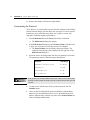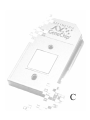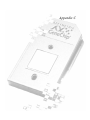
1
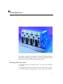
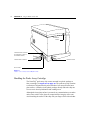
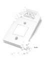
Affymetrix GeneChip Fluidics Station 400 ® ® User’s Guide Version 5.0 For use with Affymetrix® Microarray Suite Software For Research Use Only. Not for use in diagnostic procedures. Affymetrix Confidential 700103 rev 5 Trademarks ™ ™ Affymetrix®, GeneChip®, EASI™, , , , HuSNP™, GenFlex™, Jaguar®, MicroDB®, 417™, 427™ 418™, 428™, Pin-and-Ring™, NetAffx™, CustomExpress™ and Flying Objective™ are trademarks owned or used by Affymetrix, Inc. Microsoft® is a registered trademark of Microsoft Corporation. Oracle® is a registered trademark of Oracle Corporation. GeneArray® is a registered trademark of Agilent Corporation. Limited License EXCEPT AS EXPRESSLY SET FORTH HEREIN, NO RIGHT TO COPY, MODIFY, DISTRIBUTE, MAKE DERIVATIVE WORKS OF, PUBLICLY DISPLAY, MAKE, HAVE MADE, OFFER TO SELL, SELL, USE OR IMPORT PROBE ARRAYS OR ANY OTHER PRODUCT IS CONVEYED OR IMPLIED WITH THE PROBE ARRAYS, INSTRUMENTS, SOFTWARE, REAGENTS OR ANY OTHER ITEMS PROVIDED HEREUNDER. EXCEPT FOR CERTAIN ARRAYS AND REAGENTS DESIGNATED AS "ANALYTE SPECIFIC REAGENTS" (SEE APPLICABLE PACKAGE INSERT) WHICH ARE LICENSED FOR USE AS ANALYTE SPECIFIC REAGENTS OR RESEARCH USE, ALL PRODUCTS (INCLUDING THE PROBE ARRAYS, INSTRUMENTS, SOFTWARE, AND REAGENTS) DELIVERED HEREUNDER ARE LICENSED TO BUYER FOR RESEARCH USE ONLY. THIS LIMITED LICENSE PERMITS ONLY THE USE BY BUYER OF THE PARTICULAR PRODUCT(S), IN ACCORDANCE WITH THE WRITTEN INSTRUCTIONS PROVIDED THEREWITH, THAT BUYER PURCHASES FROM AFX OR ITS AUTHORIZED REPRESENTATIVE. THE PURCHASE OF ANY PRODUCT(S) DOES NOT BY ITSELF CONVEY OR IMPLY THE RIGHT TO USE SUCH PRODUCT(S) IN COMBINATION WITH ANY OTHER PRODUCT(S). IN PARTICULAR, (i) NO RIGHT TO MAKE, HAVE MADE OR DISTRIBUTE OTHER PROBE ARRAYS IS CONVEYED OR IMPLIED BY THE PROBE ARRAYS, (ii) NO RIGHT TO MAKE, HAVE MADE, IMPORT, DISTRIBUTE, OR USE PROBE ARRAYS IS CONVEYED OR IMPLIED BY THE INSTRUMENTS OR SOFTWARE, AND (iii) NO RIGHT TO USE PROBE ARRAYS IN COMBINATION WITH INSTRUMENTS OR SOFTWARE IS CONVEYED UNLESS ALL COMPONENT PARTS HAVE BEEN PURCHASED FROM AFX OR ITS AUTHORIZED REPRESENTATIVE. FURTHERMORE, PROBE ARRAYS DELIVERED HEREUNDER ARE LICENSED FOR ONE (1) TIME USE ONLY AND MAY NOT BE REUSED. THE PRODUCTS DO NOT HAVE FDA APPROVAL. NO PATENT LICENSE IS CONVEYED TO BUYER TO USE, AND BUYER AGREES NOT TO USE, THE PRODUCTS IN ANY SETTING REQUIRING FDA OR SIMILAR REGULATORY APPROVAL OR EXPLOIT THE PRODUCTS IN ANY MANNER NOT EXPRESSLY AUTHORIZED IN WRITING BY AFX IN ADVANCE. Patents Products may be covered by U.S. Patent No. 6,114,122 and other U.S. or foreign patents. Copyright ©1997-2001 Affymetrix, Inc. All rights reserved. Affymetrix® Fluidics Station User’s Guide Contents CHAPTER 1 Introduction 5 Warnings and Precautions 5 Regulatory 7 Customer Support Information 8 Instrument Components 8 Accessory Kit 10 How the Fluidics Station Works 11 CHAPTER 2 Using the Fluidics Station 400 17 Starting Up 17 Handling the Probe Array Cartridge 18 Setting Up an Experiment 19 Defining the Experiment 19 Priming the Fluidics Station 20 Hybridizing the Target Solution to the Probe Array 20 Customizing the Protocol 24 Shutting Down 25 i ii C O NT E NT S CHAPTER 3 Instrument Care and Maintenance 29 Instrument Care 29 Instrument Maintenance 29 Troubleshooting and Assistance 33 When to Contact Affymetrix Technical Support 35 APPENDIX A Removing a Module for Servicing 39 Removing a Module for Servicing 39 Replacing a Module 40 APPENDIX B Using More Than One Fluidics Station 45 Setting the Address 45 Connecting Fluidics Stations Together 46 APPENDIX C Replacing the Washblock Replacing the Washblock APPENDIX D Specifications Instrument Specifications APPENDIX E Warranty Warranty 49 49 53 53 57 57 1 Chapter 1 Introduction 1 This chapter introduces the Affymetrix® GeneChip® Fluidics Station 400 and its components, gives an overview of how the fluidics station works, and covers the safe use of the fluidics station. Warnings and Precautions ■ The fluidics station is for research use only. It is not for use in diagnostic procedures. ■ All biological specimens and materials with which they come in contact should be handled as if capable of transmitting infection and should be 5 6 C H AP T ER 1 Introduction disposed of with proper precautions in accordance with federal, state, and local regulations—including adherence to the OSHA Bloodborne Pathogens Standard (29 CFR 1910.1030) for blood-derived and other samples governed by this act. Never pipette by mouth. Avoid specimen contact with skin and mucous membranes. ■ Wear gloves when using the fluidics station. ■ Exercise standard precautions when obtaining, handling, and disposing of potentially carcinogenic reagents. ■ Do not send your instrument elsewhere for service or attempt to service it yourself. To protect your warranty and ensure safe operation, the instrument should be serviced only by Affymetrix or its representatives. If the instrument is not working correctly, please contact your Affymetrix Technical Support representative. ■ Do not use the fluidics station in ways not specified by Affymetrix. Doing so may impair the protections provided by the fluidics station. Do not place hands or fingers inside the cartridge holder. See Figure 1.1 on page 10. Under fault conditions, the area behind the cartridge holder can have temperatures that rise to 100°C or higher. ■ The fluidics station requires two people to lift and handle it safely. Each person should firmly grasp the base of the instrument at the end opposite the other to lift. Use OSHA standards for lifting techniques. The LCDs in front of the instrument are sensitive to static discharge. Avoid touching them with the fingers or any object that may be carrying an electric charge. Affymetrix® Fluidics Station User’s Guide Caution Notices: % #76+ 10 • 6JGRQYGTUWRRN[EQTFKUWUGFCUVJGOCKPFKUEQPPGEVFGXKEG'PUWTGVJCVVJG UQEMGVQWVNGVKUNQECVGFCPFKPUVCNNGFPGCTVJGGSWKROGPVCPFKUGCUKN[ CEEGUUKDNG # 6 6 ' 0 6 + 1 0 • .GEQTFQPF CNKOGPVCVKQPGUVWVKNKUÃEQOOGKPVGTTWRVGWTIÃPÃTCN.CRTKUGFG EQWTCPVFQKVÄVTGUKVWÃGQWKPUVCNNÃG´RTQZKOKVÃFWOCVÃTKGNGVÄVTGHCEKNG F CEEÃU # % * 6 7 0 ) • <WTUKEJGTGP6TGPPWPIFGU)GT¼VGUXQO0GV\KUVFGT0GV\UVGEMGT\W\KGJGP 8GTIGYKUUGTP5KGUKEJFC²FKG5VGEMFQUGNGKEJV\WI¼PINKEJKUV Regulatory This device complies with Part 15 of the FCC rules. Operation is subject to the following two conditions: (1) This device may not cause harmful interference, and (2) this device must accept any interference received, including interference that may cause undesirable operation. 7 8 C H AP T ER 1 Introduction Customer Support Information AFFYMETRIX, INC. 3380 Central Expressway Santa Clara, CA 95051 USA Tel: 1-888-362-2447 (1-888-DNA-CHIP) Fax: 1-408-731-5441 [email protected] [email protected] AFFYMETRIX UK Ltd., Voyager, Mercury Park, Wycombe Lane, Wooburn Green, High Wycombe HP10 0HH United Kingdom Tel: +44 (0) 1628 552550 Fax: +44 (0) 1628 552585 [email protected] [email protected] www.affymetrix.com Instrument Components The GeneChip® probe array Fluidics Station 400 contains four modules; each module can hold one GeneChip® probe array cartridge. The Microarray Suite software on the workstation, which is connected to the instrument, can control each of the four modules independently of the others. A single workstation can control as many as eight fluidics stations. You can use any or all of the modules at the same time. You can also choose a different protocol for each module. The modules are numbered 1 through 4 near the LCD window. The GeneChip Fluidics Station 400 includes the following components. See Figure 1.1 on page 10. Affymetrix® Fluidics Station User’s Guide 1. Sample Holder — holds the sample vial 2. Module Door — protective cover for the peristaltic pump on the module 3. Cartridge Holder — holds the cartridge during hybridization 4. Washblock — part of the cartridge holder that completes the fluid path when a cartridge is not in place (used for cleaning out or draining the fluidics station) 5. Cartridge Lever — engages or releases the cartridge holder 6. LCD Window — displays messages during processes 7. Lid Release Buttons — one on each side 8. Wash Bottles (2) — hold wash buffers and tubing that pulls buffer through system 9. DI Water Bottle — holds deionized water and tubing that pulls water through system 10. Waste Bottle — collects waste from hybridizations and washes 11. Metal Sampling Tube — fits inside the sample vial (Sample is pulled up and into the system through the sampling tube.) 12. Cartridge Needles (not shown in figure) — fit inside the septa on the cartridge or the washblock (Fluids are circulated through the cartridge via the cartridge needles.) 9 10 C H AP T ER 1 Introduction 6. LCD Window 5. Cartridge Lever 7. Lid Release Buttons 4. Washblock 8. Wash B Bottle 8. Wash A Bottle 9. DI Water Bottle 10. Waste Bottle 3. Cartridge Holder 2. Module Door 11. Metal Sampling Tube 1. Sample Holder Figure 1.1 The GeneChip® Fluidics Station 400 and components Accessory Kit The GeneChip® Fluidics Station 400 also includes an accessory kit. Contents of Accessory Kit Component Item Part Number Quantity Terminator Plug Assembly 340011 1 Cable Assembly, CPU, DB9P, M/F 350001 1 Affymetrix® Fluidics Station User’s Guide Contents of Accessory Kit Component Item Part Number Quantity Power Cord 350014 1 4A Fuse, 5 × 20 mm 370013 1 8.5" Silicone Peristaltic Tubing 400110 4 5/32" T-Handle Ball-Tip Hex Driver 400113 1 1/4" Tip Flathead Screwdriver 400115 1 Washblock Assy 400116 2 500 ml Square Media Bottle (Fluidics DI Water/Buffer) 400118 5 1000 ml Square Media Bottle (Fluidics Waste Bottle) 400119 1 9/64" T-Handle Hex Driver 400127 1 Pre-drilled Bottle Cap 400137 4 Sample Needle 410016 4 GeneChip® Fluidics Station 400 User’s Guide 700103 1 How the Fluidics Station Works For further instructions, see Using the Fluidics Station 400 on page 17. Standard Hybridization and Wash Protocol 1. Use the Microarray Suite software to define an experiment and start the fluidics station protocol. 2. After preparing the target in the laboratory according to the relevant GeneChip probe array package insert, place the labeled target solution into a sample vial. Then place the vial into the sample holder on the fluidics station. 3. Place the appropriate cartridge into the cartridge holder on the selected module of the fluidics station and close the cartridge holder by pushing the holder into the module until it clicks into place. Remove your hand from the exterior of the cartridge holder and engage the cartridge holder by lifting the cartridge lever quickly. Avoid performing these two steps in the opposite order, as doing so may damage the cartridge needles. 11 12 C H AP T ER 1 Introduction 4. 5. The target circulates through the cartridge and hybridizes to the GeneChip probe array. The fluidics station will perform the following actions to hybridize the target to the cartridge. The fluidics station will ■ draw target solution from the sample vial into the cartridge and mix it by alternately draining and filling the cartridge at a selected temperature; ■ expel the target solution into the waste or into the sample vial; ■ wash the cartridge repeatedly with wash solutions at selected temperatures; ■ fill the cartridge with wash solution for scanning; ■ clean the metal sampling tube and module tubing for the next sample. After hybridization, the Agilent GeneArray® scanner scans the cartridge by laser light to obtain fluorescence intensity data. For more information on how the scanner works, refer to the appropriate scanner manual. Sample Recovery and Staining Protocol 1. Use the Microarray Suite software to define an experiment and start the fluidics station protocol. 2. After the hybridization of the sample to the cartridge, place the cartridge into the cartridge holder on the selected module of the fluidics station. 3. Place an empty sample vial in a sample vial holder. The fluidics station transfers the sample to the empty sample vial. 4. Remove the sample vial and place a vial containing the stain solution into the sample vial holder. 5. The fluidics station will perform the following actions to stain the bound target on the cartridge and prepare it for scanning. The fluidics station will: ■ wash the array with wash solution (or solutions) at selected temperatures; ■ draw staining solution from the vial into the cartridge and mix it by alternately draining and filling the cartridge at a selected temperature; ■ expel the staining solution to the waste line; Affymetrix® Fluidics Station User’s Guide 6. ■ wash the cartridge with wash solution (or solutions) at a selected temperature; ■ fill the cartridge with wash solution for scanning; ■ clean the metal sampling tube and module tubing for the next cartridge to be processed. After staining and washing, the Agilent GeneArray® scanner scans the cartridge by laser light to obtain fluorescence intensity data. For more information on how the scanner works, refer to the appropriate scanner manual. In addition to the preceding protocols, the fluidics station can perform variations of the steps described in both procedures. For more information about the protocols that can be performed on the fluidics station, please contact your Affymetrix Technical Support representative. 13 14 C H AP T ER 1 Introduction 2 Chapter 2 Using the Fluidics Station 400 2 This section describes how to use the Affymetrix® GeneChip® Fluidics Station 400 with sample protocols. Starting Up 1. Check to ensure that the fluidics station is connected to the power main through the power cord provided. 2. Check to ensure that the fluidics station is connected to the workstation. CommLink connections are located on the back of the fluidics station. See Figure 2.1 on page 18. 3. Flip the ON/OFF switch for the fluidics station to the ON position. The switch is located on the left side of the fluidics station. See Figure 2.1 on page 18. The LCD window should display the following: 3RZHU2Q'RQH 1 2 7 3 5 , 0 (' & 4. Turn on the workstation. The Microarray Suite software should automatically open. If it does not, open the software program by doubleclicking its icon. 17 18 C H AP T ER 2 Using the Fluidics Station 400 Lid Release Button CommLink Out Connector (to terminator or cable to next fluidics station) CommLink In Connector ,2 ON/OFF Switch Power Cable Figure 2.1 Location of the serial ports and ON/OFF switch Handling the Probe Array Cartridge The GeneChip® probe array chip comes mounted in a plastic package to form a cartridge. See Figure 2.2 on page 19. The probe array chip contains a collection of oligonucleotide probes that have been arrayed on the inner glass surface. A chamber in the plastic package directly under the chip acts as a reservoir where hybridization and washing occur. Although the inner glass surface is protected, any contamination or scratches on the outer surface of the glass can compromise the integrity of the scan. Avoid touching the surface of the chip with your fingers. Skin oils and other Affymetrix® Fluidics Station User’s Guide substances, such as lotions or ink, can fluoresce. If the surface of the probe array chip is noticeably dirty, you should carefully clean the chip with a nonabrasive laboratory tissue. Plastic Package Notch Septa FRONT Probe Array on Glass Chip BACK Figure 2.2 The GeneChip® probe array cartridge Setting Up an Experiment Before running a hybridization on the fluidics station, you must first define an experiment. For information on defining an experiment, refer to the Microarray Suite software user’s guide or to the appropriate package insert. Defining the Experiment In the Microarray Suite software, open the Experiment Info dialog box under the Run menu. An Experiment Information dialog box appears. 1. In the Experiment Information dialog box, fill in the name of the experiment and select cartridge name from the drop-down list. Do this for each experiment. Refer to the Microarray Suite software user’s guide or to the appropriate package insert for additional information about the Experiment Information dialog box. 2. Save the experiment by clicking the Save button. 19 20 C H AP T ER 2 Using the Fluidics Station 400 3. Close the Experiment Information dialog box. Priming the Fluidics Station A prime is necessary to ensure that the wash lines are full of the appropriate buffer and that the fluidics station is ready to process a cartridge. You should prime the fluidics station: ■ whenever you first start the fluidics station and whenever you change the wash solutions; ■ before processing a cartridge if you have performed a shutdown on any module, and ■ if the LCD window instructs you to run a prime. 1. Check to ensure that all the wash lines are in the appropriate wash bottles. Please consult the probe array package insert that came with the cartridge kit for the appropriate wash buffer solutions, or contact your Affymetrix Technical Support representative. 2. If it is not already open, open Fluidics under the Run menu on the computer workstation. ⇒ The Fluidics Station dialog box appears. If more than one fluidics station is present, select the one to be primed in the drop-down list. 3. In the Fluidics Station dialog box, click Protocol, then choose Prime for each module under the Protocol drop-down list. Click the Run button for each module to be primed. ⇒ Follow the instructions in the LCD window as the prime progresses. You must load a standard 1.5 mL microcentrifuge tube in the sample holder of each module that is to be primed. The LCD window on the fluidics station and the Fluidics Station dialog box will indicate the status of the prime and when priming is completed. Hybridizing the Target Solution to the Probe Array After you have primed the fluidics station, it is ready to hybridize a sample. For more specific information on hybridizing the target to the probe array cartridge, refer to the appropriate package insert. Affymetrix® Fluidics Station User’s Guide 1. If it is not already open, click Fluidics under the Run menu on the workstation. ⇒ The Fluidics Station dialog box appears. If more than one fluidics station is present, select the appropriate instrument from the dropdown list. 2. In the Fluidics Station dialog box, select the module that is ready for use and choose the experiment name in the drop-down Experiment list. Check to ensure that the experiment name matches the sample and cartridge to be run. 3. In the Protocol drop-down list, choose the protocol that matches the cartridge type. You can also choose a customized hybridization-wash or wash protocol here. Refer to the Microarray Suite user’s guide or to Customizing the Protocol on page 24. If you are running a customized protocol, check the parameters of each of the protocols chosen to be sure they are appropriate for your experiment. This can be done in the Fluidics Protocol dialog box found by choosing Edit Protocol under the Tools menu. 4. Click the Run button to begin hybridization of the sample. ⇒ The protocol will begin.The LCD window on the fluidics station and the Fluidics Station dialog box on the workstation will indicate the status of the hybridization as it progresses. 5. Follow the instructions on the LCD window or in the Fluidics Station dialog box. A selection of the available prompts is given below as examples: a. If prompted to “Remove Vial,” remove any remaining vial from the sample holder of the fluidics station. b. If prompted to “Load Cartridge,” open the cartridge holder by pressing down on the cartridge lever to the Eject position. Place the appropriate cartridge into the cartridge holder corresponding to the module set up in the experiment. Push the cartridge holder back to engage the latch See Figure 2.3 on page 22. After you hear a light click, push firmly up on the cartridge lever, which inserts the cartridge needles into the septa. 21 22 C H AP T ER 2 Using the Fluidics Station 400 Do not push the lever all the way up until the cartridge hold is latched. Doing so will bend the cartridge needles. c. If prompted to “Load Vial,” place the experiment sample vial into the sample holder on the fluidics station. As the hybridization progresses, check to ensure that the cartridge is filling properly and that bubbles are not forming. If it is not filling properly, see the note below in this chapter. Figure 2.3 Inserting the cartridge into the cartridge holder 6. When the hybridization or washing is complete, the LCD window should display the following: (MHFW&DUWUL GJH Affymetrix® Fluidics Station User’s Guide 7. Eject the cartridge by pushing down on the cartridge lever. The LCD window should display the following: (QJDJH:DVKEO RFN If bubbles are present in the cartridge, return it to the cartridge holder. Latch the cartridge holder by gently pushing it inward until you hear a light click. Engage the cartridge by pushing up on the cartridge lever to the Engage position. The fluidics station will drain the cartridge and then fill it with a fresh volume of the last wash buffer used. When it is finished, if the LCD window displays EJECT CARTRIDGE again, remove the cartridge and inspect it again for bubbles. If no bubbles are present, it is ready to scan. Proceed to step 10. If you have made ten attempts to fill the cartridge without bubbles and have been unsuccessful, the fluidics station will no longer display EJECT CARTRIDGE after refilling the cartridge. Instead, it will terminate with the prompt DO CLEAN CYCLE. Remove the cartridge and run the Cleanout procedure on the particular module. Fill the cartridge manually by inserting a pipette tip or syringe needle through the bottom septum and by using a second pipette tip or syringe needle in the top septum to permit air to escape. Refer to Troubleshooting and Assistance on page 33 for possible causes and solutions to bubbles appearing in the cartridge. 8. Latch the cartridge holder by pushing up on the lever to engage it. You should hear a light click. Confirm that you have securely latched the cartridge holder before pushing up the lever. 9. Engage the washblock by pushing up on the cartridge lever to the Engage Position. 10. The fluidics station will automatically perform a Cleanout procedure. The LCD window will indicate the progress of the Cleanout procedure. When the Cleanout procedure is complete, the LCD window should display the following: 5HPRYH9LDO 23 24 C H AP T ER 2 Using the Fluidics Station 400 11. Remove the sample vial from the sample holder. Customizing the Protocol To be effective, you must modify a protocol before starting it on the fluidics station. Protocol changes will not affect runs in progress. For more specific instructions, refer to the Microarray Suite user’s guide or contact your Affymetrix Technical Support representative. 1. Select Edit Protocol from the Tools menu on the workstation. ⇒ The Edit Protocol dialog box appears. 2. In the Edit Protocol dialog box under Protocol Name, click the arrow to open a list of protocols. Click the protocol to be changed. ⇒ The Protocol Name text box displays the protocol name. The conditions for that protocol are displayed on the right side of the Edit Protocol dialog box. 3. Select the item to be changed and enter the new parameters as needed. The parameters must be within the ranges shown below: Parameter Valid Range Hybridization or Stain Time (Seconds) 0 to 86,399 Temperature (°C) 15 to 50 Number of Wash Cycles 0 to 99 Mixes per Wash Cycle 1 to 99 Enter 0 (zero) for the hybridization time if you desire only a wash. Enter 0 (zero) for the number of wash cycles for a wash solution that you will not use. 4. To return to the default values for the protocol selected, click the Defaults button. 5. Once you have modified all the protocol conditions, click the Save button to save the modified protocol. To save the modified protocol under a different name, enter the new name in the Protocol Name box before clicking the Save button. Affymetrix® Fluidics Station User’s Guide 6. Click the Close button to leave the dialog box. Shutting Down You should perform the Shutdown procedure at the end of a session. Do not keep the fluidics station on if you will not use it again within the next 12 hours. The instrument runs the risk of salt buildup. 1. Replace wash bottles with bottles filled with deionized water. 2. From the Protocol drop-down list, choose Shutdown for all modules and then click the Run button for all modules. 3. Follow the instructions that appear in the LCD window. As with the prime procedure, a 1.5 mL microcentrifuge tube is required for each module. 4. After the Shutdown protocol is complete, flip the ON/OFF switch to the OFF position. 25 26 C H AP T ER 2 Using the Fluidics Station 400 3 Chapter 3 Instrument Care and Maintenance 3 This chapter provides instructions on caring for and maintaining the instrument, and on troubleshooting if problems arise. Instrument Care ■ Use a surge protector on the power line to the fluidics station. ■ Always run a Shutdown protocol when the instrument will be off or unused overnight or longer. This will prevent salt crystals from forming within the fluidics system. ■ When not using the instrument, leave the sample holder in the raised position with an empty vial in it. This will prevent leakage of any fluids from the sample line into the system or onto the tabletop. ■ Always use distilled or deionized water to prevent contamination of the lines. Change buffers with freshly prepared buffer at each system startup. ■ The fluidics station should be positioned on a strong, level bench away from extremes in temperature and away from moving air. Instrument Maintenance To ensure proper functioning of the fluidics station, you should perform periodic maintenance. Weekly Maintenance 1. To open the top to the fluidics station, firmly push the lid release buttons located on the sides of the fluidics station. See Figure 1.1 on page 10. 2. Check the overflow tray for liquid. If liquid is present, absorb it with disposable wipes. See Figure 3.1 on page 30. 29 30 C H AP T ER 3 Instrument Care and Maintenance Waste Conduit Overflow Tray Figure 3.1 Open chassis of fluidics station 3. Check for salt deposits around tubing and fittings. Clean around tubing and fittings with a cotton swab if deposits are present. If deposits persist, there may be a leak in the tubing or fittings. Call Affymetrix Technical Support if you suspect a leak. Preventive Maintenance Peristaltic tubing is included in the accessory kit that comes with the fluidics station. As needed, replace the peristaltic pump tubing as follows: Wear gloves when changing tubing, and do not allow fluid from old tubing to spill onto surfaces. Affymetrix® Fluidics Station User’s Guide 1. Open the drop-down door to the module to access the peristaltic pump tubing. See Figure 3.2 on page 31. Peristaltic Tubing Figure 3.2 Module open, showing peristaltic tubing 2. Open the white clamps to release tubing on both sides. See Figure 3.3 on page 32. Do not attempt to replace the tubing on a module where the module has been removed from the case of the fluidics station. 31 32 C H AP T ER 3 Instrument Care and Maintenance White Clamp Figure 3.3 Releasing peristaltic tubing 3. Pull tubing off while gently turning the peristaltic pump head. Discard old tubing. 4. Replace tubing with new peristaltic tubing supplied with the accessory kit as described below: 5. a. Attach one end of the new tubing to the fitting on the right at the top of the pump enclosure. b. Insert the tubing into the clamp under the fitting without stretching the portion of the tubing between the fitting and the clamp. There should be a small amount of slack in that portion of the tubing. c. Work the tubing into the pump head while slowly turning the pump. d. Insert the free end of the tubing into the other clamp, and attach it to the other fitting. e. Close the drop-down module door. Order more replacement tubing. Affymetrix® Fluidics Station User’s Guide Troubleshooting and Assistance If problems arise with the fluidics station, use the following table to locate the description that matches the problem. If you cannot find a solution, call Affymetrix Technical Support for assistance. Problem Possible Cause Solution Cartridge not filling completely with sample solution or buffer during initial stages of hybridization wash or staining protocol. Possible holes in the septa of the cartridge Run Recover script, then use another cartridge. Sample or staining solution not in place properly Run Recover script. Make sure sample or stain vial is in the sample holder. Insufficient volume of sample or staining solution (500 µL) Run Recover script. Add more sample solution to the sample vial. Blocked sampling tube or line of the fluidics station Run Recover script. Run the Clean or Prime script with fresh deionized (DI) water to flush out salt blockage. Failure of one of the fluidics sensors Call Affymetrix Technical Support for service. Pump tubing stretched too tightly around the pump Loosen the tubing clamps, allow tubing to relax, close the clamps. Buffer bottle empty Fill buffer bottles. Deionized water used instead of buffer Replace water with buffer, and prime instrument lines. Module not primed Prime module. Recovered less sample than initial input during Recover script Loose tubing attachments inside the fluidics station Call Affymetrix Technical Support for service. “Fluidics Station X Does Not Respond” error message on workstation Power not switched on at the fluidics station Turn fluidics station power on, then try to connect again. Incorrect fluidics station designated for communication Designate correct fluidics station on workstation. Loose cables Firmly connect cables to fluidics station. No user response to “Remove Vial” prompt or other prompt Start the selected script again. Displayed as “Missing Fluid Error.” Cartridge not filling completely with buffer during wash script. Displayed as “Missing Fluid Error.” “Sensor Timeout” error message on workstation 33 34 C H AP T ER 3 Instrument Care and Maintenance Problem Possible Cause Solution “Error While Draining” or “Error While Filling” error message on workstation Defective septa in cartridge Use a new cartridge. Insufficient sample or stain volume Add more sample solution to sample vial. Excessive bubbling in cartridge Change the buffer: reduce detergent. Buffer conductivity too low Change the buffer: increase salt. Failure of one of the fluid sensors Call Affymetrix Technical Support for service. “Temperature Timeout” error message on workstation Fluidics station not at the designated temperature in time Call Affymetrix Technical Support for service. Air bubbles left in cartridge at the end of a hybridization-wash script Air bubble in wash line See Hybridizing the Target Solution to the Probe Array on page 20 Buffer leaking inside the fluidics station Loose tubing attachments inside the fluidics station Call Affymetrix Technical Support for service. Washblock requires replacement Refer to Appendix C, Replacing the Washblock on page 49 Salt buildup in the lines of the fluidics station Run the Clean or Prime script with fresh DI water to flush out salt blockage. Possible defective septa on the cartridge Use another cartridge. Extra flashing on the cartridge Use another cartridge, or call Affymetrix Technical Support for service. Salt buildup on the cartridge needles Run the Clean script with fresh DI water to flush out salt blockage. Clean cartridge needles with a wet cotton swab. Cartridge holder aligned and attached to the fluidics station improperly Call Affymetrix Technical Support for service. Cartridge needles of the fluidics station not engaging with the cartridge Cartridge holder not properly engaged Place the cartridge into the cartridge holder. Push the holder door shut, and to the fluidics station firmly lift the lever to engage the cartridge needles. Affymetrix® Fluidics Station User’s Guide When to Contact Affymetrix Technical Support Under any of the following conditions, unplug the instrument from the power source and contact Affymetrix Technical Support: ■ when the power cord is damaged or frayed; ■ if any liquid has penetrated the instrument; ■ if, after service or calibration, the instrument does not perform to the specifications stated in Appendix D. If the instrument must be returned for repair, call Affymetrix Technical Support. AFFYMETRIX, INC. 3380 Central Expressway Santa Clara, CA 95051 USA Tel: 1-888-362-2447 (1-888-DNACHIP) Fax: 1-408-731-5441 [email protected] [email protected] AFFYMETRIX UK Ltd., Voyager, Mercury Park, Wycombe Lane, Wooburn Green, High Wycombe HP10 OHH United Kingdom Tel: +44 (0) 1628 552550 Fax: +44 (0) 1628 552585 [email protected] [email protected] www.affymetrix.com 35 36 C H AP T ER 3 Instrument Care and Maintenance A Appendix A Removing a Module for Servicing A Removing a Module for Servicing Affymetrix Technical Support may request that a module be disconnected to be serviced. Follow these steps to disconnect a module from the fluidics station. 1. Open the top to the fluidics station by firmly pushing the lid release buttons located on the sides of the fluidics station. See Figure 1.1 on page 10. 2. Disconnect the three reagent tubing lines from the tubes that connect to the reagent manifold (¼-turn quick-disconnect fittings), leaving them attached to the module. Loosely tuck the tubing into the top of the module. 3. Open the Fluidics Station dialog box on the computer workstation, and select the module to be removed. 4. Choose Drain for the module to be removed, and click the Run button. 5. After the Drain is completed, turn the power off to the fluidics station and unplug it from the outlet. Do not attempt to remove a module without turning off power to the fluidics station. 6. Disconnect the two waste tubing lines connected to the waste conduit, leaving them attached to the module. Loosely tuck the tubing into the top of the module. Do not allow liquid from the tubing lines to drip into the main compartment or module. 39 40 A P PE N DI X A 7. Unscrew the two screws on the bottom of the front bezel of the fluidics station by using the 5/32” hex key included in the accessory kit. 8. Unscrew the three horizontal screws on the top of the bezel (inside the instrument), using the 5/32” hex key included in the accessory kit. 9. On all modules, remove all cartridges, latch all cartridge holders, and place all cartridge levers in the neutral, or horizontal, position. 10. Pull the white bezel off the front of the fluidics station. 11. With the flathead screwdriver included in the accessory kit, unscrew the bottom screw of the module to be removed. 12. Unscrew the two top screws, using the 9/64” hex key included in the accessory kit. 13. Pull the module forward to disconnect it from the fluidics station. 14. Replace the front bezel, and return power to the fluidics station. You can continue to use the remaining modules. Replacing a Module To replace a serviced module, follow these instructions: 1. Turn the power off to the fluidics station, and unplug it from the outlet. Do not attempt to replace a module without turning off power to the fluidics station. 2. Open the top to the fluidics station by firmly pushing the lid release buttons located on the sides of the fluidics station. See Figure 1.1 on page 10. 3. Unscrew the four screws on the bottom of the front bezel of the fluidics station, using the 5/32” hex key included in the accessory kit. 4. Unscrew the three horizontal screws on the top of the bezel (inside the instrument), using the hex key included in the accessory kit. 5. Remove all cartridges, latch all cartridge holders, and place all cartridge levers in the neutral, or horizontal, position on all modules. Affymetrix® Fluidics Station User’s Guide 6. Pull the white bezel off the front of the fluidics station. 7. Push the serviced module back into its housing in the fluidics station. Be sure it connects to the connector in the back. 8. Attach the two top screws by using the 9/64” hex key included in the accessory kit. 9. With the flathead screwdriver included in the accessory kit, attach the bottom screw of the module to the fluidics station. 10. Attach the white bezel to the front of the fluidics station with the three horizontal screws on the top of the bezel, using the 5/32” hex key included in the accessory kit. 11. Attach the two screws to the bottom of the front bezel of the fluidics station, using the hex key included in the accessory kit. 12. Connect the two waste tubing lines on the module to the waste conduit. 13. Connect the three reagent tubing lines on the module to the reagent manifold, following the color code (red to red, white to white, blue to blue). 14. Close the top of the fluidics station, and restore power. 15. Prime the module. 41 42 A P PE N DI X A B Appendix B Using More Than One Fluidics Station B Using one workstation, you can connect up to eight fluidics stations together. Follow these steps to connect more than one fluidics station to the workstation. When making connections, always turn off power to all devices in the chain. Failure to do so can cause loss of information. Setting the Address Setting the address on the fluidics stations will enable the computer to recognize and correctly control each of the fluidics stations. Each fluidics station connected to a given workstation must have a unique address. You must assign addresses consecutively starting with 1. It is preferable, though not necessary, to number the fluidics stations in the order in which they are connected. Fluidics station #3 Fluidics station #2 Fluidics station #1 Workstation terminator Figure B.1 Addressing fluidics stations consecutively 1. Use a pen or pencil to set each of the three DIP switches on the back of the fluidics station to the ON or OFF position, according to the desired address. Push up for ON and down for OFF. All three DIP switches need to be set. Use the following table as a guide. 45 46 A P PE N DI X B DIP Switch Settings for the Fluidics Station Address D Left Middle Right ON ON ON = 1 ON ON OFF = 2 ON OFF ON = 3 ON OFF OFF = 4 OFF ON ON = 5 OFF ON OFF = 6 OFF OFF ON = 7 OFF OFF OFF = 8 Connecting Fluidics Stations Together 1. Insert the plug end of a nine-pin serial cable into the serial board on the workstation. 2. Insert the other end of the cable into the CommLink In nine-pin connector on the back of the first fluidics station. 3. Insert a second nine-pin serial cable into the CommLink Out (socket) nine-pin connector on the back of the first fluidics station. 4. Insert the other end of the cable into the Comm Link In nine-pin connector on the back of the second fluidics station. 5. Connect the remaining fluidics stations in a chain following the above pattern. 6. Insert a terminator plug into the Comm Link Out (socket) nine-pin connector on the back of the last fluidics station in the chain. C Appendix C Replacing the Washblock C Replacing the Washblock 1. Open the top to the fluidics station by firmly pushing the lid release buttons located on the sides of the fluidics station. See Figure 1.1 on page 10. 2. Unscrew the two screws on the bottom of the front bezel of the fluidics station, using the 5/32” hex key included in the accessory kit. 3. Unscrew the three horizontal screws on the top of the bezel (inside the instrument), using the same hex key included in the accessory kit. 4. On all the modules, remove all cartridges, latch all cartridge holders, and place the cartridge levers in the neutral, or horizontal, position. 5. Pull the white bezel off the front of the fluidics station. 6. Eject the washblock by pushing the cartridge lever down. 7. Using a Phillips head screwdriver, unscrew the two screws in the cartridge holder of the washblock that needs replacing. 8. Mount the new washblock in the cartridge holder. Confirm that the washblock is in the proper orientation, i.e., that the top of the washblock is even with the top of the sensor block, and that the dimples on the washblock lock into the front of the cartridge holder. Apply a small amount of Loctite (222 ms) to the nylon screw threads or the washblock threads. Install screws and tighten until the screws bottom out. Back off approximately ¼ turn. 9. Prime the module. During priming, observe the new washblock for leaks. If leaks occur, stop the Prime script, loosen the four Phillips screws in the corners of the cartridge holder, adjust the front part of the cartridge holder until the cartridge needles appear to pass through the centers of the holes in the 49 50 A P PE N DI X C washblock, and gently tighten the screws. Repeat this step until no leaks occur during priming. 10. With the three horizontal screws on the top of the bezel, and using the 5/32” hex key included in the accessory kit, attach the white bezel to the front of the fluidics station. 11. Attach the four screws to the bottom of the front bezel of the fluidics station, using the same hex key included in the accessory kit. 12. Close the top of the fluidics station. D Appendix D Specifications D Instrument Specifications Fluidics Station Dimensions: (height, depth, width) 40.2 x 41.0 x 71.1 cm or 15 13/16 x 16 1/8 x 28 inches Product Weight: Approximately 80 pounds Power Input: 100 to 240 V~, 3 A 300 watts or less Main supply voltage fluctuations not to exceed 15% of the nominal supply voltage. Temperature: Operating: 15° to 30°C Storage (non-operating):-10° to 60°C Humidity: Operating: 10-90% RH, non-condensing Storage (non-operating):10% to 95% RH Other: Pollution degree, 2 Installation category, II Electrical Supply The electrical supply shall meet the input specified on the instrument label. Voltage fluctuations shall not exceed 15% nominal supply voltage. Altitude <2000m 53 54 A P PE N DI X D E Appendix E Warranty E Warranty The Affymetrix® Genechip® Fluidics Station 400 is warranted to the buyer by Affymetrix. Please refer to the Affymetrix Terms and Conditions received with this instrument at time of sale for information on the warranty. 57 58 A P PE N DI X E Index Index Affymetrix® Fluidics Station 400 User’s Guide Index A P accessory kit 10 precautions 5 preventive maintenance 30 probe array 18 protocol C care 29 components customizing 24 staining 12 wash 11 instrument 8 customizing protocol 24 E R recovery experiment setting up 19 staining 12 regulatory 7 removing module 39 F fluidics station more than one 45 fluidics stations connecting 46 H hybridization S sample recovery 12 setting up an experiment 19 shutting down 25 staining protocol 12 starting up 17 standard 11 hybridization and wash protocol 11 hybridizing T target solution hybridizing 20 target solution 20 I instrument components 5 M maintenance 29 modules 8 W warnings and precautions 13 warranty 57 61