1
Publication No. 980806-999 Rev. A
1260A Option 01T User Manual
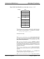
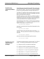
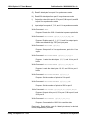
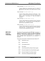
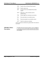
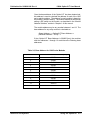
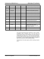
Note that there are no control registers at EVEN addresses. Only
the odd addresses contain control registers.
There are three types of relay control schemes employed by the
1260 series switch modules:
Single Channel = Single Bit
For the majority of relay modules, one channel is operated by
setting or clearing a single bit in a control register on that
module. When the bit is set, the corresponding relay is
closed. When the bit is cleared, the relay is opened.
Single Channel = Multiple Bits
There are a few modules, such as the 1260-54, where
multiple bits are operated to select a single channel. For the
1260-54, control bits for a single channel are located in
different control registers.
Single Channel = Special Case
There are two other modules which do not use the onebit/one-channel paradigm.
The 1260-45 operates a
row/column arrangement of control registers to operate
matrix relays. The 1260-60 uses latching relays, where one
control bit must be pulsed to close a relay, and another bit
must be pulsed to open the relay.
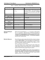
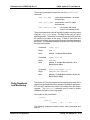
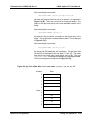
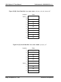
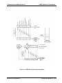
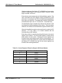
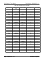
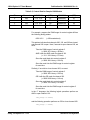
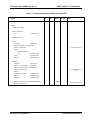
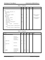
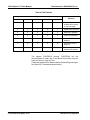
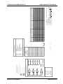
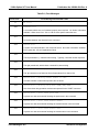
Appendix C of this manual contains control register information for
each of the 1260 series modules. For illustrative purposes,
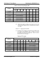
portions of the data for two of the modules is shown in Table 2-4.
Astronics Test Systems
Using The Option-01T 2-73