1
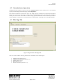
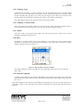
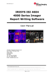
Jan 2007 IPU 40129 issue 2 IRISYS ISI 4604 4000 Series Imager Report Writing Software User Manual InfraRed Integrated Systems Ltd Park Circle, Tithe Barn Way Swan Valley Northampton NN4 9BG Tel: (0) 1604 594200 Fax: (0) 1604 594210 Email: [email protected] 2007 InfraRed Integrated Systems Ltd Page 1 of 18 Jan 2007 IPU 40129 issue 2 Contents: 1 INTRODUCTION .................................................................................................................................... 3 1.1 1.2 YOU WILL NEED: ................................................................................................................................ 3 END RESULT:....................................................................................................................................... 3 2 QUICK REPORT GENERATION......................................................................................................... 3 3 INSTALLATION ..................................................................................................................................... 4 3.1 3.2 3.3 4 CONTENTS OF THE REPORT WRITER PACKAGE .................................................................................... 4 PC SYSTEM REQUIREMENTS ............................................................................................................... 4 INSTALLATION OF SOFTWARE ONTO PC............................................................................................... 4 USING REPORT WRITER .................................................................................................................... 4 4.1 LAUNCHING THE SOFTWARE ............................................................................................................... 4 4.2 INTRODUCTION TO OPERATION ........................................................................................................... 5 4.3 TITLE PAGE TAB ................................................................................................................................. 5 4.3.1 Company Logo............................................................................................................................ 6 4.3.2 Company or Client Name ........................................................................................................... 6 4.3.3 Author ......................................................................................................................................... 6 4.3.4 Date ............................................................................................................................................ 6 4.3.5 General Comments ..................................................................................................................... 6 4.4 IMAGE SELECT TAB ............................................................................................................................. 7 4.4.1 Thermal Image Folder Search.................................................................................................... 8 4.4.2 Thermal Image Select ................................................................................................................. 9 4.4.3 Visual Image Folder Search ..................................................................................................... 10 4.4.4 Visual Image Select .................................................................................................................. 10 4.5 INSPECTION DATA TAB ..................................................................................................................... 11 4.5.1 Line Drawing............................................................................................................................ 11 4.5.2 Inspection Name ....................................................................................................................... 12 4.5.3 Operator ................................................................................................................................... 12 4.5.4 Location.................................................................................................................................... 12 4.5.5 Equipment................................................................................................................................. 12 4.5.6 Comment................................................................................................................................... 12 4.5.7 Load.......................................................................................................................................... 12 4.5.8 Temperature Measurement Information ................................................................................... 12 4.5.9 Repair Priority.......................................................................................................................... 12 4.5.10 Fault / Recommended Action.................................................................................................... 13 4.5.11 Inspection, Repair & Re-inspection Dates................................................................................ 13 4.6 GENERATE OR SAVE? ........................................................................................................................ 13 4.7 MENU ................................................................................................................................................ 13 5 SAMPLE INFRARED REPORT.......................................................................................................... 14 5.1.1 5.1.2 5.1.3 5.1.4 Title Page.................................................................................................................................. 14 Contents Page........................................................................................................................... 15 Inspections................................................................................................................................ 16 Report Summary ....................................................................................................................... 17 6 PRINTING .............................................................................................................................................. 18 7 CUSTOMER FEEDBACK FORM....................................................................................................... 18 Page 2 of 18 Jan 2007 IPU 40129 issue 2 1 Introduction This user manual describes how to use the IRISYS 4000 Series Report Writer software. The software has been produced by IRISYS for people requiring a report after performing a thermography inspection survey with an IRISYS 4000 series thermal imager. It simplifies the process of combining the following into an infrared report: 1. 2. 3. thermal images, information that is required to assess the condition of a target object, visual images if required. 1.1 You Will Need: 1. 2. 3. 4. The IRISYS 4000 Series Report Writer Software – included on the CD provided with Report Writer. The correct USB software protection dongle – also provided with Report Writer. IRISYS InfraRed Image files (.iri), taken using an IRISYS 4000 series imager and transferred to a PC – see your IRISYS imager user manual for details on how to save thermal images, and how to transfer them to a PC. Visual images from a digital camera (although not required, these can aid the understanding of a thermography inspection, and can be included if relevant). Note: IRISYS recommends that thermal and visual images are copied from memory cards to a folder on the PC’s hard disk, rather than being read directly from memory devices. 1.2 End Result: The IRISYS 4000 Series Report Writer creates an infrared report in html format. This can be read in a multitude of internet browsers, and is therefore easy to distribute. The report can include a company logo, an automatically generated contents page, general information about the thermographic survey, thermal images and visual images, specific information about each thermal image and finally an automatically generated report summary. The contents page is useful if many inspections are included in the report, and the summary can be used to plan a maintenance schedule as repair priorities can be displayed. 2 Quick Report Generation 1. Install IRISYS Report Writer onto the PC. See Section 3.3 for more details. 2. Insert the USB dongle. 3. Launch IRISYS 4000 Series Report Writer from the desktop. See Section 4.1 for more details. 4. The “Title Page” tab opens as default. Use this tab to enter general information about the infrared report. See Section 4.3 for more details. 5. Select the “Image Select” tab. Use this tab to select the thermal images and visual images that will be included as “inspections” in the infrared report. See Section 4.4 for more details. 6. Select the “Inspection Data” tab. Use this tab to add specific information about individual inspections. Select “Next” or “Previous” to add information about other inspections in the report. See Section 4.5 for more details. 7. Click “Generate Report” to create the infrared report now, or select “Save” or “Save As…” from the file menu to complete the report at a later date. See Section 4.7 for more information. 8. The report opens in an internet browser window. Print the infrared report from this window. See Sections 5 & 6 for more information. Page 3 of 18 Jan 2007 IPU 40129 issue 2 3 Installation 3.1 Contents of the Report Writer Package The package includes a CD-Rom, which contains the software and user manual, and a USB dongle, which is required to run the software. 3.2 PC System Requirements The PC should be IBM compatible running MS Windows XP or 2000, with Internet Explorer version 6 or greater and a USB port. 3.3 Installation of software onto PC The software is on the supplied CD-Rom. 1. 2. 3. 4. Insert the “4000 Series Report Writer” CD-Rom into the PC’s CD-Drive. Double click on ‘My Computer’ and then on the CD-Drive. Double click on ‘4000 Series Report Writer Setup.exe’. Follow the on screen prompts to complete the installation. Note: The IRISYS Report Writer software will be installed by default into the following path: C:\Program Files\IRISYS\IRISYS 4000 Series Report Writer The above path and name can be changed during the installation, but it is advisable to leave it as the default. The installation will also put a ‘Shortcut Icon’ onto the PCs desktop to allow quick and easy start-up of the software. 4 Using Report Writer 4.1 Launching the Software Insert the USB dongle provided into a USB port on the computer. Launch the IRISYS Report Writer program from the Desktop icon, Figure 1: Report Writer Desktop Icon Or from: START/PROGRAMS/IRISYS/IRISYS 4000 Series Report Writer. Figure 2: Report Writer Start Menu Location. When launched, the window obtained will be similar to Figure 3. Page 4 of 18 Jan 2007 IPU 40129 issue 2 4.2 Introduction to Operation The Report Writer software is used to create one “infrared report”, which contains one or more itemized reports (each including one thermal image) called “inspections”. The software window has a menu with “File” and “Help” options, the functions of which are described in Section 4.7. It also has “Title Page”, “Image Select” and “Inspection Data” tabs which are selected by clicking on the tab labels. These tabs are used to input general information into the infrared report and to create a number of “inspections”. When the software is launched, the “Title Page” tab is selected by default. 4.3 Title Page Tab Figure 3: Report Writer Title Page Tab. This tab is used to add the following information to the header of the infrared report: 1. 2. 3. 4. 5. Company Logo (Section 4.3.1). Company or Client Name (Section 4.3.2). Author (Section 4.3.3). Date (Section 4.3.4). General Comments (Section 4.3.5). Page 5 of 18 Jan 2007 IPU 40129 issue 2 4.3.1 Company Logo If desired, click “Set Image” to insert a company logo into the image frame at the top of the infrared report’s title page. The “Set Image” button opens a search window that displays the Windows folder structure and .bmp and .jpg files only, as these are the image file types that can be imported. Once selected, images can be removed by selecting a new image, or by clicking “Clear Image”. Note: When Report Writer opens, the logo last used is selected by default. 4.3.2 Company or Client Name This is the name of the company whose site is being surveyed. After entering the company name, it becomes the default for all reports made on your PC, but it is easily changed if required. 4.3.3 Author This is the name of the infrared report author. Note that camera operator’s names can be entered separately as explained in Section 4.5.3. 4.3.4 Date The default is to display today’s date. Select whether or not to display the date of infrared report generation by clicking on the radio buttons. If the default is not correct click on the list box and the calendar will appear as shown in Figure 4. Figure 4: Select the Date From The Calendar. Note: When loading previously saved .IRR files, the original date remains and is not overwritten by today’s date. 4.3.5 General Comments Comments can be added to assist with the understanding of the infrared report when read at a later date. Typical examples include company visited, site location, contact details of site manager, initial reason for site visit etc. When all the appropriate information has been added to the infrared report, click on the “Image Select” tab. It is possible to return to the “Title Page” tab to edit this information at any time before the html report is generated. Page 6 of 18 Jan 2007 IPU 40129 issue 2 4.4 Image Select Tab This tab (see Figure 5) is used to select which thermal images (file extension .iri) are to be added to the infrared report. Please see the imager user manual for information on how to transfer thermal images from a handheld imager to a PC. This page is also used to match up these thermal images with any related digital camera visual images. Figure 5: Report Writer Image Select Tab. The following sections give a detailed description of how to: 1. Search for a folder of thermal images to open - Section 4.4.1. 2. Add the required thermal images to the report - Section 4.4.2. 3. Search for a folder of visual images - Section 4.4.3. 4. Add the required visual images to the report, and associate them with thermal images already in the report - Section 4.4.4. Page 7 of 18 Jan 2007 IPU 40129 issue 2 4.4.1 Thermal Image Folder Search To find a folder containing thermal images: • Click “Browse” on the left hand side of the page and search for the required IRI snapshot folder using a standard search window. Only folders and .iri files will be displayed. Figure 6: Thermal Image Folder Search To open a folder of thermal images: • Either double-click a thermal image within the required folder, or single click one and then press “Open”. Figure 7: Opening a Thermal Image Folder Note: A thermal image must be selected to load the snapshot folder. • Alternatively if the location of the saved thermal images is known, the folder path can be typed into the text box labeled “Snapshot Folder” and then “Refresh” can be clicked. Figure 8: Opening a Thermal Image Folder Page 8 of 18 Jan 2007 IPU 40129 issue 2 All the thermal images in the selected folder will appear as thumbnail images in the frame below the “Browse” and “Refresh” buttons as shown In Figure 5. Thumbnails include all of the temperature measurement cursors available. Thermal images (.iri files) transferred directly from an IRI 4010 to a PC for use in “IRISYS 4000 Series Report Writer” have a maximum of 2 temperature measurement cursors, whilst it is possible to add up to 10 temperature measurement cursors to images in the “IRISYS 4000 Series Imager” software application. If there are more thumbnails to display than the available space permits, a scrollbar appears beside the frame. 4.4.2 Thermal Image Select To add a thermal image from the selected “Snapshot Folder” to the infrared report: • Click on a thermal image thumbnail. This will make the thermal image appear in the preview frame at the bottom left-centre of the page. If the image is required in the report, click “Add”. TIP: simply double-click a thumbnail to add a thermal image directly. This will make the thermal image thumbnail appear in the central column. Figure 9: Adding a Thermal image to the Report • If all of the thermal images in the folder are required, click “Add All”. To remove thermal images from the central column, first click on the thermal image (which will highlight it in blue) and then click “Remove”. To remove all thermal images, click “Remove All”. Notes: 1. 2. 3. Repeat sections 4.4.1 and 4.4.2 if thermal images are required from multiple snapshot folders. Removing thermal images from the infrared report will also remove any associated visual images and any text you may have entered for this inspection in the “Inspection Data” Tab. The header of the central column of the “Image Select” tab displays how many “inspections” will be included in the report. Page 9 of 18 Jan 2007 IPU 40129 issue 2 4.4.3 Visual Image Folder Search The same procedure is used to add visual images to the infrared report. To find a folder containing visual images: • Click the “Browse” button on the right hand side of the page to search for and open the folder required. Only folders, .bmp and .jpg files will be displayed. To open a visual image folder: • Double-click a visual image within the required folder, or single click one and press “Select”. • Alternatively type the path of the visual image folder into the text box on the right of the page and click “Refresh”. All the .jpg and .bmp files in the selected folder will appear as thumbnail visual images in the frame below the “Browse” and “Refresh” buttons as shown in Figure 5. If there are more thumbnail visual images to display than the available space permits, a scrollbar appears beside the frame. 4.4.4 Visual Image Select To add a visual image from the selected “Image Folder” to the infrared report: • Click on the thermal image in the central column to which the visual image is related by clicking on it. This will highlight it and also make it appear in the preview frame at the bottom left-centre of the page. Figure 10: Highlighted Thermal image • Click on a thumbnail visual image to see the image preview in the bottom right-centre of the page. Click “add” if it matches the previewed thermal image in the bottom left-centre of the page. TIP: simply double-click a thumbnail visual image to add it directly. • If all of the visual images in the folder are required and the images are in the same order as the thermal images, highlight the first thermal image in the central column and click “Add All”. • To remove visual images from the central column, first click on the visual image and then click “Remove”. To remove all visual images, click “Remove All”. Notes: 1. 2. Repeat sections 4.4.3 and 4.4.4 if visual images are required from multiple visual image folders. If visual images are to be added to the infrared report, they must be added to thermal images already in the central column of the “Image Select” tab. After the required thermal images have all been added to the infrared report (and matched with visual images where relevant) click on the “Inspection Data” tab. It is possible to return to the “Image Select” tab to enter more inspections at any time before the html report is generated. Page 10 of 18 Jan 2007 IPU 40129 issue 2 4.5 Inspection Data Tab This tab (see Figure 11) is used to enter information specific to each thermal image. The tab generates a one page “inspection” per thermal image. To cycle through the inspections, click “Previous” or “Next” at the top of the page. If 3 thermal images have been entered on the “Image Select” tab, the page will initially display inspection 1 of 3. The information that can be entered is listed below: Line Drawing (Section 4.5.1). Inspection Name (Section 4.5.2). Operator (Section 4.5.3). Location (Section 4.5.4). Equipment (Section 4.5.5). Comment (Section 4.5.6). Load (Section 4.5.7). Temperature Measurement Information (Section 4.5.8). Repair Priority (Section 4.5.9). Fault / Recommended Action (Section 4.5.10). Inspection, Repair & Re-inspection Dates (Section 4.5.11). Figure 11: Report Writer Inspection Data Tab. 4.5.1 Line Drawing The software has the ability to draw lines onto the thermal image (and visual image if available) to help the reader of the report to identify the points of interest. For example in Figure 12 below, the hot breaker has been identified in both the thermal image and the visual image. Figure 12: Drawing Lines to Identify Hotspots. Page 11 of 18 Jan 2007 IPU 40129 issue 2 This is done on the “Inspection Data” tab by clicking once on part of the combined visual and thermal image to create one end of the line, and then by clicking elsewhere in the image to create the other end of the line. The controls for drawing lines are shown in Figure 13. The line thickness can be adjusted by selecting a number between 1 and 9 from the “Pen Size” list box, and the colour of the line can be adjusted by clicking “Change”, and selecting a colour from the popup Figure 13: Line Drawing Controls. palette. Clicking “Undo” removes drawn lines one at a time or all the lines can be removed by clicking “Clear”. 4.5.2 Inspection Name The inspection name appears in the contents page of the infrared report, and therefore it is recommended that the inspection name includes enough information to identify the thermal image. 4.5.3 Operator This is the camera operator’s name (for this inspection). Note that the software allows an individual entry for each inspection, allowing inspections from different operators to be included in the infrared report. Also note that the report author is entered separately (see Section 4.3.3). 4.5.4 Location This is the inspection location, such as site name, building name, floor number or area. 4.5.5 Equipment Description of equipment, for example “fan motor” or “main breaker panel”. 4.5.6 Comment This is for comments specific to the equipment and inspection. For example, detailed location information, tools required for access, access time limitations etc. 4.5.7 Load Measured and rated load on equipment, and measured load as a percentage of rated load. Load can include current and voltage measurements, rotation speeds, weights lifted etc. 4.5.8 Temperature Measurement Information Depending on how many cursors are selected in the thermal image, up to two colour coded temperature measurements can be displayed here. If you have added more than 2 cursors to the image file using the “IRISYS 4000 Series Imager” software, you can select which 2 you would like to display. If you select 2 cursors, the temperature difference between them is also displayed. The emissivity and ambient temperature values are also included so it is possible to make an accurate evaluation of the temperature of the target(s). 4.5.9 Repair Priority Repair priority (1 low to 5 high) can be added to indicate the severity of the fault. This appears in the infrared report summary and can be used as part of a continuous maintenance program or for a one-off inspection. Page 12 of 18 Jan 2007 IPU 40129 issue 2 4.5.10 Fault / Recommended Action Description of the fault found, and details of recommended action. This section can also be used to explain the repair priority given above. 4.5.11 Inspection, Repair & Re-inspection Dates The date and name of operator for inspection repair and re-inspection can be included. Note that infrared reports can be saved (see File menu commands in section 4.7) after initial inspection and reopened at a later date to fill in date of repair and re-inspection, and information about the repair can be added to the “Fault / Recommended Action” text box. When the information for this inspection has been correctly entered, click “Next” at the top of the page to fill in data for other inspections in the same manner. When this is finished there are three saving options. 4.6 Generate or Save? 1. If the infrared report is ready for printing, select “Save” or “Save As” from the “File” menu on the toolbar to save the report information as an .IRR file. This enables you to return to edit the report at a later date if required. See Section 4.7 for more information. Now click “Generate Report” at the bottom of the “Inspection Data” tab. This will open a “Save As” window to save the infrared report in html format. When the report is saved, the images from the inspections (and a company logo if included) are saved as bitmaps (.bmp) into the same location as the report. These bitmaps are required for the html report to display properly. It is therefore recommended to save reports into new folders if there are a large number of inspections in a report. The infrared report will open in an internet browser window. Note: It is not possible to return to edit the report (including repair and re-inspection details) unless it is saved as an .IRR first. 2. If more report information needs to be added at a later date, select “Save” or “Save As” from the “File” menu on the toolbar to save the infrared report in progress as a .IRR file. See Section 4.7 for more information. 3. If more information or images need to be added to the report now, it is possible to reselect the “Title Page” or “Image Select” tabs as required. 4.7 Menu The File menu allows the following: • • • • • • New – Opens a blank Report Writer window. Open… – Opens a search window so existing .IRR files can be found and opened. Save - saves the current IRR document or opens a Save As window if the current document is "Untitled" Save As… - Opens a “Save As” window to save a report as an .IRR file with a new name. Recently opened .IRR files will be listed here. Exit – Exits the IRISYS Report Writer program. Note: The html infrared report cannot be edited, so it is recommended to save the report information as an .IRR file before closing Report Writer. The Help menu displays information about the program, including the software version number. Page 13 of 18 Jan 2007 IPU 40129 issue 2 5 Sample Infrared report The infrared report is saved in html format, and will open in an internet browser window as shown below. 5.1.1 Title Page The first page of the infrared report shows a company logo if required and is titled “Infrared report”. The information previously entered on the “Title Page” tab (Company, Author, Date, and General Comments) appears here. Page 14 of 18 Jan 2007 IPU 40129 issue 2 5.1.2 Contents Page The second page is an automatically generated contents page, detailing which inspection appears on which page of the infrared report. It also gives the page number of an automated infrared report summary. Page numbers are usually added to the infrared report automatically by internet browsers during printing. Page 15 of 18 Jan 2007 IPU 40129 issue 2 5.1.3 Inspections The number of inspection pages corresponds to the number of thermal images included in the infrared report. Each inspection shows all of the information entered during the “Inspection Data” stage, and they also show some information gathered from the thermal image file: 1. 2. 3. Up to two colour coded temperature measurement pixels are highlighted on the thermal image. Up to two pixel temperature measurements and the difference in temperature between the two are shown below the thermal image. The date and time that the thermal image was taken. Note: The time and date information comes from the 4000 series imager the image was saved on, and if these settings are not set correctly on the imager, then the time will not be correct in the image file. 4. The emissivity and reference ambient temperature, as entered into the imager. Note: If these details are incorrect, the image properties can still be altered using the IRISYS PC imaging software. Page 16 of 18 Jan 2007 IPU 40129 issue 2 5.1.4 Report Summary At the end of the infrared report there is an automatically generated report summary that gives the following details about each inspection: 1. 2. 3. 4. 5. Inspection number, which is taken from the order the thermal images were entered. Location, Equipment, Fault / action Priority (1 Low, 5 High). This summary makes it easy to plan a maintenance schedule using the priority values given for each inspection. Page 17 of 18 Jan 2007 IPU 40129 issue 2 6 Printing The infrared report is now complete and can usually be printed by selecting “Print” from an internet browser’s “File” menu on the toolbar. Print on either A4 or Letter paper, and ensure the page margins in “File/Page Setup” are set to the default for the paper size. As an alternative to printing, the html file can be emailed to a customer or client. In this case, the generated bitmap images must also be emailed as the html file requires these if it is to display correctly. 7 Customer Feedback Form If you have any feedback or have had any technical issues with an IRISYS Thermal Imager or the Report Writer software, please complete the details below and send it back to IRISYS at the address on the front page of this manual. Name: Company name and address: Contact details: Thermal Imager part number and serial number: Imaging software version installed: Report Writer software version installed: Description of technical fault/feedback: Page 18 of 18