1
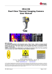
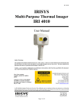
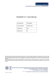
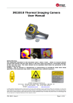
IR Series PC Software
User Manual
InfraRed Integrated Systems Ltd
Park Circle, Tithe Barn Way, Swan Valley, Northampton, NN4 9BG, UK
Tel: +44 (0) 1604 594200
Fax: +44 (0) 1604 594210
Email: [email protected]
www.irisys.co.uk
© 2011 InfraRed Integrated Systems Limited (Irisys). No part of this publication may be reproduced without prior permission in writing
from Irisys. Whilst Irisys will endeavor to ensure that any data contained in this product information is correct, Irisys do not warrant its
accuracy or accept liability for any reliance on it. Irisys reserve the right to change the specification of the products and descriptions in
this publication without notice. Prior to ordering products please check with Irisys for current specification details. All brands and
product names are acknowledged and may be trademarks or registered trademarks of their respective holders.
IPU 40340 issue 2
Page 1 of 20
Contents
1. Installing the IR series software onto a PC. ............................................................. 3
2. Transferring saved images from the camera to the PC. ............................................. 3
2.1. Direct from Camera ........................................................................................ 3
2.2. From Micro SD Card ........................................................................................ 4
3. Using the IR series software. ................................................................................. 4
3.1. Starting the Software. ..................................................................................... 4
3.2. Opening an image. ......................................................................................... 4
3.3. Analysis Tools ................................................................................................ 6
3.4. Menus and Toolbars ...................................................................................... 11
4. Report Writer..................................................................................................... 17
4.1. Title Page tab ............................................................................................... 17
4.2. Image select tab. ......................................................................................... 18
4.3. Inspection Data tab. ..................................................................................... 20
IPU 40340 issue 2
Page 2 of 20
1. Installing the IR series software onto a PC.
To install the IR Thermal imager software onto a PC:
1.
Insert the CD into the PC.
2.
Use Windows Explorer to view the files on the CD.
3.
Open and run the file “IR series PC setup.exe”.
4.
This will install the software on to the PC.
Once the software has successfully been installed a
icon appears on the PC Desktop.
2. Transferring saved images from the camera to the PC.
In the camera the images are saved on a micro-SD card and are in folders. A new folder is
created every time the camera is switched on. The folder also contains the voice message file
if it is recorded. Each saved image will therefore consist of two or three files.
a.
A BMP file containing the thermal and visual image.
b.
An IR5 file containing the temperature data.
c.
A WAV file if a voice recording was made when the image was saved.
Note: Do not use the Microsoft Scanner and Camera Wizard to download images.
Use Windows Explorer.
There are two ways to transfer images to the PC.
2.1. Direct from Camera
a) Connect the camera to the PC via the USB cable. Note that the camera does not
need to be switched on.
b) Use Windows Explorer and filing system to locate the micro SD card in the camera.
This will normally be shown as a removable disk.
c) Copy the complete folders from the SD card on to the PC. Note that there are at
least two files for each image, which must be kept together.
IPU 40340 issue 2
Page 3 of 20
2.2. From Micro SD Card
a) Take the micro-SD card out of the camera and insert into a suitable card reader.
b) Connect the card reader to the PC.
c) Use Windows Explorer to locate the files with the images on the micro-SD card and
copy the complete folders on to the PC. Note that there are at least two files for
each image, which must be kept together.
3. Using the IR series software.
The PC software has two main parts.
1.
Analysis Mode – Allows the user to analyse the image and also alter the settings for
how the image is displayed.
2.
Report Writer Mode - Allows the user to create a report of the thermal images for
records and administration and operational use.
3.1. Starting the Software.
Double Click on the IR series icon to start the software
.
The following window will appear.
Note it may be necessary to maximise the window.
3.2. Opening an image.
Click on the drop down File menu and click on “Open”.
Use the Windows Explorer to locate the folder where the images are saved. If viewing images
directly from the camera this will be shown as a removable disk.
IPU 40340 issue 2
Page 4 of 20
Once the folder is located, double click on the image to be loaded.
Opening Screen shot.
The window format shown below should be displayed. It may be necessary to maximise the
window in order to see all the features.
Toolbar.
Tabs for Display, Cursors, and
Settings
Temperature
scale for the
image.
Image.
Visible and thermal
image alignment.
Level and Span Adjustment bar.
Image Description
The thermal image is seen on the right hand side of the screen. A temperature scale relating
to the colours is displayed to the right of the image. An adjustable span, also showing a
histogram of temperatures in the image is shown at the bottom of the screen. There is a drop
down menu bar and an icon toolbar. A set of Tabs is on the left hand side of the image. On
start up the display tab is shown.
IPU 40340 issue 2
Page 5 of 20
3.3. Analysis Tools
To analyse an image and change its presentation the tools available are:1. Drop down menus.
2. Icon Toolbar.
3. Tabs.
TABS
Display Tab
IPU 40340 issue 2
Page 6 of 20
1. Temperature span allows the image display span values to be altered manually
by clicking on the Figures in the boxes and changing them. Auto span sets the
temperature span values based on the temperature values in the image.
The temperature span can also be adjusted using a mouse in the level and span
adjustment bar (see below). To adjust span click on the dark grey and light grey
border and drag. To adjust level click in the middle of the light grey area and
move.
Level and span
adjustment bar.
2. Colour palette. To change the colour palette, click on the arrow button.
1
2
1.
2.
3.
4.
White Hot Mono.
Ironbow.
Rainbow.
Isotherm Style.
3
4
5
5.
6.
7.
8.
6
7
8
Hot Metal.
High Contrast.
16 step Rainbow.
Black Hot Mono.
3. Visible blend. To change the visible/infrared ratio click on the arrow button.
0% Thermal.
IPU 40340 issue 2
50% Thermal
50% Visible
100% Visible.
Picture in picture
Page 7 of 20
4. Interpolation. To change the interpolation click on the arrow button.
x1
x2
5. Zoom factor. To change the zoom setting click on the arrow button. The
following four settings are available X1,X2,X3,X4
(examples of X1, X2 and X4 shown below).
x1 Zoom
X2 Zoom
X4 Zoom
When zoomed to x2 or more, the part of the image diplayed can be selected by
means of the mouse in the Pan Control box.
6. Area Select. Use the arrow button to select a small, medium, or large area for
measurement (see page 14).
7. Image alignment. This allows the vertical and horizontal alignment of the
thermal and visible images. Clicking on the navigation arrows will move the
visible image while the infrared image remains stationary. It is easiest to adjust
with a 50% thermal and 50% visible image.
Note: Clicking on the reset button returns the alignment to the setting when the file
was opened.
IPU 40340 issue 2
Page 8 of 20
Cursors tab
Up to 10 cursors can be added to the display.
1. To add a cursor to the image, double click on the image on the screen.
The cursor can be moved by the drag and drop method.
2. To remove cursors either double click on it or highlight the cursor in the box
and click remove.
The list of cursors within the box shows:1. The temperature of the cursors.
2. The position of those cursors.
3. The emissivity value. This can be set individually.
a.
Select the cursor by clicking on its name in the table.
Then either:
b.
Click on the double arrow on the side to call up the emissvity look up
table, and then click on the set button.
Or:
c.
Use the emissivity value adjustment box.
Emissivity Setting
IPU 40340 issue 2
Look up table
Page 9 of 20
Settings tab
1. Units:
o
2. Reflected Temp.:
Change using the arrow buttons or type in the box.
3. Global Emissivity:
0.01 to 1.00. Change using the arrow buttons or type in
the box.
4. >> button
Access the emissivity look up table
5. Capture Time:
Change if required using the arrow buttons.
6. Capture Date:
Change if required using the arrow buttons.
7. Comments:
Type in any comments in the box.
8. Caption
Any text caption typed when saving the image will appear
here.
9. Voice annotation
Voice notes recorded when saving the image can be
replayed via the play button. These can be heard from the
PC’s speakers.
IPU 40340 issue 2
C, oF, K. Change using the arrow button.
Page 10 of 20
3.4. Menus and Toolbars
Use either the drop down menus or the icons on the toolbar to carry out various operations.
Drop down menus
Icons toolbar.
File
Items 1 and 2 below are also available via the icons on the toolbar.
1.
2.
3.
4.
5.
Open. Use Windows Explorer to open an image.
Save. To save changes to the image.
Save As. To save the image with a different file name.
Revert. To discard all changes since the last save.
Excel output. Selecting this provides the temperature values of all pixels in a CSV
format allowing it to be saved as a file. This can then be read as an Excel
spreadsheet. Note that the file must be opened from within the Excel application
(not by “double-clicking” on the file) and selecting comma delimiters.
IPU 40340 issue 2
Page 11 of 20
Edit
1. Copy…
2. Copy To Bitmap…
This offers the option to copy the image to the clipboard or to save as a bitmap. Both
of these options will allow three choices - Full window, Snapshot or Snapshot+.
Full window.
Full window saves the
complete window.
IPU 40340 issue 2
Snapshot.
Snapshot saves the
image only.
Snapshot +.
Snapshot + saves the
image and the colour
temperature scale.
Page 12 of 20
View
Items 3 onwards are also available via the icons on the toolbar.
1. Toolbar. Turns on/off the icon toolbar.
2. Status Bar. Turns on/off the status bar at the bottom of the screen.
3. Measurement Cursors List. Toggles to show the temperature value and position
of the active cursors. The value of the hottest and coldest points in the image
(see item 5 below) and the area box values (item 7 below).
4. Measurement Cursors. Toggles between displaying or removing the cursor/s on
the image.
Cursors on image
IPU 40340 issue 2
No Cursors.
Page 13 of 20
5. Cursor Temperature. Toggles between displaying cursor/s with temperature vales
besides them or the cursor number.
6. Hot & Cold Cursors. Allows the display of the hottest and coldest point of the
whole image.
7. Area Select. Selects an area in the middle of the image. The maximum,
minimum and average temperatures of the area box are displayed in the cursor
list (item 3 above). Three different area sizes are available (see page 8).
Small Area
Medium Area
Large Area
8. Blue Isotherm.
9. Red Isotherm.
Isotherms are regions within the scene of the same temperature range and are
shown in the same colour. This is best seen using either the white hot or Black
hot colour schemes.
Red Isotherm
IPU 40340 issue 2
Blue isotherm
Both Isotherms
Page 14 of 20
The red and blue isotherms can be
set by adjusting the red and blue
blocks in the level and span
adjustment bar. This can be done
using a mouse.
To adjust the isotherm width, click
on the colour block edge and drag.
To adjust the level, click in the
colour block and move.
The
temperature
difference
between the centres of the two
isotherms is displayed at the
bottom.
10. Profiles. A temperature profile is a histogram showing the temperature values
through a cross-section of the scene. The profiles are displayed as shown below.
The cross-section lines can be moved by the user. The temperature indicated in
each isotherm is of the point indicated by the green line. This can be moved
along the isotherm by the mouse.
11. Options. Toggles to display the Tabs panel.
Options on – Tabs displayed
Option off.
12. Report Writer. This will toggle between the Analysis Mode and Report Writer
Mode.
IPU 40340 issue 2
Page 15 of 20
Tools
1. Reset Isotherms. Reset the isotherms to the default values.
2. Language. The following languages can be selected. Once a language is selected
exit the IR series software and re-start it to activate the selection.
Help
This is also available via the icon on the toolbar.
About. Shows the software version.
IPU 40340 issue 2
Page 16 of 20
4. Report Writer
It is possible to toggle between the IR series Analysis Mode and the Report Writer Mode from
the drop down view menu or the toolbar.
There are three steps to creating a report. There is a separate tab for each function.
1. Title page.
2. Image select.
3. Inspection Data.
Enter details that should appear in the title page of the report.
This allows the selection of the images needed for the report.
Information and additional data about each image can be added
and then the report can be generated.
4.1. Title Page tab
1. When the Report Writer Mode is opened the title page appears as shown above. There is
an empty space where a logo or other image can be placed to appear on the front page of
the final report.
2. Press the select image button.
3. Windows Explorer can now be used to find an image.
4. Click on the open button to select and place an image or logo in the title page.
Enter the rest of the details required for the front page of the report.
IPU 40340 issue 2
Page 17 of 20
4.2. Image select tab.
1. The screen shown below appears.
2. Click on the browse button to open Windows Explorer.
3. Highlight an image and click on the open button, or simply double click on a IR series
image.
IPU 40340 issue 2
Page 18 of 20
4.
All the Images in that folder will now appear in the browser selection on the left of the
window.
5.
Click on a selected image in the browser section and it appears in the image preview
section on the right of the window.
6.
The add/add all remove/remove all buttons allow the selection and removal of images as
required.
7.
Selected Image/s will appear in the inspection section in the centre of the window.
IPU 40340 issue 2
Page 19 of 20
8. Each image, when selected, may be edited by means of the “Edit Image” button. This
switches to the Analysis Mode. When editing is complete, switch back to the Report
Writer Mode by means of the “Toggle Report Writer” button.
4.3. Inspection Data tab.
1. The inspection Data window will appear.
1. Complete and enter data as required for the report. The image can be edited if required
by clicking on the edit image button.
2. Once data is entered press the Save Project Report button to save the full report. This
allows the report to be edited later if required.
3. Press the Generate PDF Report button when ready to create the report.
4. A report is now generated and can be saved where required.
IPU 40340 issue 2
Page 20 of 20