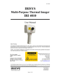
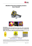
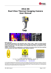
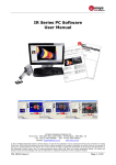
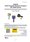
1
IPU 40151 Issue 2 IRISYS Universal Thermal Imager Type IRI 1020 User Manual Safety Warning. The equipment described in this document uses a Class 2 laser. Under no account should anyone look directly into the laser beam or the laser beam exit aperture, irreversible damage to the eye may occur. The laser should not be operated when there are personnel in the imager’s field of view. Caution – use of controls or adjustments or performance of procedures other than those specified in this document may result in hazardous laser radiation exposure. InfraRed Integrated Systems Ltd. Park Circle, Tithe Barn Way Swan Valley Northampton NN4 9BG United Kingdom Tel +44 (0) 1604 594 200 Fax +44 (0) 1604 594 210 Email: [email protected] Website: www.irisys.co.uk 2007 InfraRed Integrated Systems Ltd. No part of this publication may be reproduced without prior permission in writing from Infrared Integrated Systems Ltd. This document gives only a general description of the products and except where expressly provided shall form no part of any contract. From time to time changes may be made in the products. 1 of 15 IPU 40151 Issue 2 CONTENTS Section Page 1.0 GETTING STARTED ................................................................................................... 3 1.1 CONTENTS............................................................................................................... 3 1.2 UNPACKING ............................................................................................................. 3 1.3 POWERING THE IRI 1020 .......................................................................................... 3 1.4 USING BATTERY POWER............................................................................................ 3 1.5 BATTERY RECHARGE TIME ......................................................................................... 4 1.6 USING AC MAINS POWER .......................................................................................... 4 1.7 BATTERY CHARGING ................................................................................................. 4 2.0 OPERATING ............................................................................................................. 5 2.1 HARDWARE.............................................................................................................. 5 2.2 SWITCHING ON........................................................................................................ 5 2.3 SCREEN DISPLAY ITEMS............................................................................................ 6 2.4 OPERATING NOTES................................................................................................... 6 2.5 BUTTONS ................................................................................................................ 7 2.6 ARROW AND CENTRE BUTTON ................................................................................... 7 2.7 HOTKEY BUTTONS .................................................................................................... 8 3.0 IMAGE ADJUSTMENT................................................................................................. 9 4.0 USER SETTINGS ...................................................................................................... 10 5.0 USING THE LASER POINTER...................................................................................... 10 6.0 THERMAL IMAGE TRANSFER FROM IRI 1020 TO A PC ................................................... 10 7.0 INSTALLING SOFTWARE ON A PC .............................................................................. 11 7.1 OPERATING IRI 1020 IMAGER SOFTWARE .................................................................. 11 7.2 USING THE IRI 1020 THERMAL IMAGER WITH A PC ..................................................... 11 7.3 THERMAL IMAGER LAUNCH WINDOW......................................................................... 12 7.4 THERMAL IMAGER TOOL BAR .................................................................................... 12 7.5 FILE ....................................................................................................................... 12 7.6 EDIT ...................................................................................................................... 13 7.7 VIEW ..................................................................................................................... 13 7.8 TOOL ..................................................................................................................... 13 7.9 WINDOWS .............................................................................................................. 13 7.10 ABOUT ................................................................................................................... 13 8.0 OPERATING NOTES AND PRECAUTIONS. TEMPERATURE MEASUREMENT ........................ 14 9.0 LENS, TABLES AND CUSTOMER ................................................................................. 14 9.1 LENS...................................................................................................................... 14 9.2 EMMISIVITY LOOK UP TABLE .................................................................................... 14 9.3 CUSTOMER FEEDBACK ............................................................................................. 15 2 of 15 IPU 40151 Issue 2 1.0. Getting Started This User Manual refers to the IRISYS Universal Thermal Imager type IRI 1020. If you are familiar with thermal imagers, see the Quick Reference Guide. 1.1. Contents You will find the standard items as listed below: a) Imager. b) Charger. c) Battery. d) SD Card, e) SD Card reader. f) SD Card reader USB cable. g) CD Rom (manual, software manual, quick user guide). h) Wrist strap. i) Tool box. 1.2. Unpacking After unpacking the IRI 1020 toolbox, as seen in figure 1, inspect all the items. If any item is damaged or missing, notify your dealer immediately. Figure 1. Imager toolbox. 1.3. Powering the IRI 1020 The IRI 1020 Thermal Imager operates from either the rechargeable battery pack or from AC mains power. 1.4. Using Battery Power 1. Make sure the Thermal Imager is turned off. 2. Open up the battery compartment on the bottom of the IRI 1020 thermal imager by sliding the battery cover off as indicated in figure 2. 3. Insert the rechargeable battery as shown. 4. Replace the battery cover. 5. The above method also applies to replacing the battery, but make sure the IRI 1020 is switched off before removing the battery. 3 of 15 IPU 40151 Issue 2 Figure 2. Inserting the Rechargeable Battery. Remove Battery Cover 1.5. Insert Battery Replace Battery Cover Battery Recharge Time. The rechargeable battery will power the IRI 1020 thermal imager for approximately 6 hours. The battery indicator appears on the screen when the imager is switched on. It has the following four stages and each stage corresponds to approximately two hours of operation as seen in figure 3. Figure 3. Battery Indicator Levels. 6hrs 4hrs 2hrs 0hrs CAUTION: If the IRI 1020’s battery indicator flashes, the battery power is running low and it needs to be charged or replaced within 10 minutes. 1.6. Using AC Mains Power. 1. Make sure the thermal imager is turned off. 2. Connect the provided 12V power supply into the socket on the side of the IRI 1020 imager as seen in figure 4. 3. Attach the appropriate supplied regional adapter to the power supply. 4. Plug the power supply into a mains socket. 5. Switch on the thermal imager. CAUTION: When using AC mains, use only the power supply included with the IRI 1020. Using other power supplies may damage the IRI 1020 Thermal Imager. NOTE: The mains power supply included with the IRI 1020 is for powering the IRI 1020; it will also recharge the batteries. 1.7. Battery Charging. The IRI 1020’s battery can be charged in the imager by inserting the 12V power supply into the DC socket under the door on the side of the IRI 1020 imager, as seen in figure 4. It takes approximately 6 hours to fully charge a fully depleted battery if the imager is switched off. Charging the battery with the imager switched on takes longer. 4 of 15 IPU 40151 Issue 2 Figure 4. Connecting the Mains AC Power Supply. 2.0. Operating the IRI 1020 Practical use of the IRI 1020 is detailed in this section. 2.1. Hardware The IRI 1020 is designed for use as a handheld thermal imager. Thermal images stored on the supplied memory card, can be transferred to a PC or laptop computer using the memory card reader. PC software is for viewing and analysis of saved thermal images. Figure 5 shows the imager’s main features, including the laser pointer button and aperture, imager lens, battery compartment, power button and the door to the SD card slot. Figure 5. The IRI 1020 Hardware. Laser Pointer Aperture Lens On/Off Button Door to the SD Card Slot Laser Pointer Button Battery Compartment Safety notice: The laser used in this device is designated Class 2. Under no circumstances should personnel look straight into the laser. 2.2. Switching On Figure 6. Switching on the IRI 1020. • The IRI 1020 features an On/Off power button above the display. The IRI 1020 is switched on and off by holding the power button down for more than one second. See figure 6 for the location of the On/Off button. • For best measurement results the imager should be switched on at least 5 minutes before use. On/Off Button Warning: Please be aware that the thermal shock experienced by a camera when it is taken from one ambient environment to another may lead to inaccurate temperature readings. In accordance with thermography best practice, it is recommended that a stabilisation time of at least 30 minutes is allowed, with the unit switched on, before making temperature measurements. 5 of 15 IPU 40151 Issue 2 2.3. Screen Display Items. Figure 7. Screen Display Items. Temperature measurement cursors, their temperature measurement values, and their temperature difference value (∆). Battery life Indicator. Temperature scale with the maximum & minimum values of the span. The centre green circle to which the laser pointer is aligned at a distance of 1.5m. Emissivity value and reflected background temperature value, not displayed if the full display is selected. Four hot button icon CAUTION: The calibrated temperature output is the figure adjacent positions. to the cursor identifier; the temperature scale and display colours are for indication only. 2.4. Operating Notes. Radiometry All objects give off an IR signal which depends on the temperature of the object. For objects which are not reflective (or shiny), the amount of IR can be used to estimate the object temperature - even at a distance. The temperatures of the objects whose images fill the small green cursors are shown in the chosen temperature units at the top of the screen. CAUTION: The temperature of objects smaller than these boxes may be hotter than the reported value. Emissivity and Reflected Background Emissivity has a maximum of 1 and minimum of 0 and is the opposite of reflectivity, an emissivity of 1 means that the object is not at all shiny and an emissivity of close to 0 means that it is very shiny indeed. The IRI1020 can compensate for the emissivity of a viewed object if the emissivity is entered into the camera. If the emissivity is less than 1, the object is partly shiny and therefore some of the IR picture will have come from the surrounding background. The average background temperature must therefore also be entered into the camera. Measurement accuracy falls at low emissivities and so the value entered into the camera is limited to be no less than 0.2. CAUTION: Objects with low emissivity may be considerably hotter than the reading given by the IRI1020. The power-on value of emissivity is 1.0 and the background temperature is not then taken into account. The current emissivity and background temperature values are displayed at the top of the screen in the single cursor mode. 6 of 15 IPU 40151 Issue 2 Integration The output of the radiometer is subject to noise in the electronics and in the infrared detector. The noise can be reduced by increasing the integration setting. This averages several pictures together to reduce the noise but at the expense of slower response when the camera or the viewed object is moved. Level and Span In order to get a visible picture, the IRI1020 focuses on a certain temperature range. This is automatically determined and the temperature range is shown on the right hand side of the screen. The LEVEL is the value at the centre of the scale and the SPAN is the difference between the top value and the bottom value. Only objects in the centre third of the picture are taken into account by the IRI1020 in arriving at the automatic level and span. If the manual mode is entered, the level and span will be locked at their current values but can be adjusted by the arrow keys. This can be useful if comparative pictures of two different objects are required or if small variations in a hot or cold object are to be measured. Entering automatic mode at any time will restore a usable picture. Over and under range values are indicated by red or blue coloured numbers, these readings exceed the range of the instrument and should not be relied upon. 2.5. Buttons Operation of the IRISYS 1020 imager is by means of the 4 hotkey buttons, hotkey 1 to hotkey 4, the 4 directional arrow buttons, the centre button and the laser button. The hotkey buttons are mainly used to give control of the following functions. (See figures 9, 10 and 11 for the button locations.) The centre button turns the imager freeze function on and off except when hotkey 2 cursor is selected. Figure 8. Buttons and Hotkeys. Hotkeys 1 -4 Centre button Up/Down Left/Right Direction Arrow Buttons 2.6. Arrows and Centre Button. The directional buttons seen in figure 9, are used for four different functions, up, down, left and right. Figure 9. Directional buttons. Up Left Right Down 7 of 15 IPU 40151 Issue 2 The centre button is located in the centre of the directional arrow buttons as seen in figure 10. Pressing the centre button in normal operation freezes the images so that it can be viewed or stored to memory, see hotkey 3 below. Figure 10. Centre button. Centre button. 2.7. Hotkey Buttons Below are the icons as they appear on the IRI 1020 display. Hotkey 1 Pressing hotkey 1 toggles between the following options:- E is for the setting of Emissivity and the value can be adjusted by using the up, down, left and right, directional arrow keys. The default value is 1.0. Reflected temperature can be adjusted up and down by use of the up, down, left, right arrow keys. Note Reflected temperature – When the emissivity is set to values less than 1.0, measurement accuracy can be further improved by setting the reflected temperature compensation. The reflected temperature is the temperature being “seen” by the object being imaged. The value entered must be within the range -20ºC to 200ºC or equivalent in ˚F or K. Temp scale (°C, °F, K) degrees Celsius, degrees Fahrenheit or Kelvin can be selected by toggling the up, down, left, right directional arrow keys. This icon is for the setting of Integration and is changed by use of the up, down, left and right directional arrow keys. Palette. The user can select from three options. The palettes are Red – Blue, Green – Blue or Greyscale and are selected by toggling the up, down, left, right directional arrow keys. Clock. To alter Day, Month, Year, Hour, Minute press the centre button (figure 7), to select down, left, right arrow keys. The date format DD/MM/YYYY can be changed to MM/DD/YYYY or YYYY/MM/DD by toggling hotkey 2 until the desired setting then pressing hotkey 3 to save and exit this section. 8 of 15 IPU 40151 Issue 2 Hotkey 2 This button selects either of the two temperature measurement cursors, or the full screen option. When one of the cursors is selected, the arrow buttons are used to adjust the position of the selected cursor. Please see the icons below as they will appear on the imager display. The centre button toggles cursor two on and off. When both cursors are on, the temperatures of both, and the difference between them are displayed at the top of the screen. When full-screen is selected the arrow keys activate the full screen on and off. Full screen. Cursor one. Cursor two. Hotkey 3 In save mode, press the centre button once to freeze an image and a second time to save the image as an image.snp file to the SD card. The file saving takes a few seconds and the file name is given a sequential number. In load mode, use up and down arrows to cycle through stored snapshots. Use left and right arrows to cycle though 10 snapshots at a time. NOTE: The imager files must retain their file name (iri_1020XXXX.snp), if they are renamed on the PC they will no longer be readable by the imager. Loading. Saving. No SD card. No Files Saved. Hotkey 4 This button toggles between auto and manual mode. In auto mode, the imager continually adjusts the level and span to achieve the optimum image. In manual mode it is possible to manually control the level and span to produce an image to your requirements. Please see the icons below as they will appear on the imager display. Auto Level & Span Manual Level & Span 3.0 Image Adjustment In manual mode, use the Up and Down directional buttons to change Level, and Left and Right buttons to change Span. Manual Level and Span Settings icons will appear on the imager display. Level Up Level Down Maximum Level Minimum Level Span In Span out Maximum Span Minimum Span 9 of 15 IPU 40151 Issue 2 4.0. User settings. User settings – For the convenience of the user, some settings are persistent, the settings and values are remembered when the IRI 1020 is switched off . Those settings are: Emissivity, Reflected temperature, Temperature units, Integration & Clock. 5.0. Using the Laser pointer. When the IRI 1020 is switched ‘ON’, the laser may be activated by pressing and holding down the laser button. Figure 11. Laser pointer. Laser The laser pointer, as seen in figure 11, is used to illuminate and identify features in the image. The laser pointer illuminates the area of the scene that coincides with the green circle indicator on the display. The laser is aligned to objects at a distance of 1.5m from the lens front. 6.0. Thermal Image Transfer from the IRI 1020 to a PC. The Secure Digital (SD) memory card is the IRI 1020’s storage device for thermal images. This is also used to transfer thermal images to a PC when used with the SD card reader. Note that the imager will not be able to save thermal images without the SD card installed. 1. Save thermal images onto the SD card 2. Remove the SD card. 3. Slot the SD card into the SD/MMC slot on the USB SD card reader supplied, making sure of the correct orientation. Figure 12. Inserting the SD card. 4. Insert the USB connector of the SD card reader into a USB port on the PC, using the extender USB cable if required. 5. Follow the card reader’s installation instructions if prompted by Windows. 6. Either open “My Computer” and copy the .snp files from the SD card to the PC (recommended), or leave the SD card in place whilst the “IRISYS 1000 Series Imager” PC software is running and open the files directly from the SD card. NOTE: Image files must retain their file name (IRI1020_XXXX.snp). If they are renamed on the PC they will no longer be readable by the imager. Warning: If the Imager SD memory card is removed from the imager and reformatted using a PC, the SD memory card will take on the format of that device. When the SD memory card is then returned to the imager the SD memory card will not be readable by the imager and the message “No MMC/SD card” will appear. The SD memory card MUST be reformatted with its original file format (either FAT or FAT16) 10 of 15 IPU 40151 Issue 2 7.0. Installing Software on PC. The PC should be IBM compatible running Microsoft Windows 2000, XP or Vista with a USB port and 24 bit colour graphics. If a laptop PC is used, a TFT display is recommended. The software is on the supplied CD-Rom. 1. 2. 3. 4. 5. Insert the supplied CD-Rom into the PC’s CD-Drive (D:) or (E:) Double click on “My Computer” and then on the CD-Drive (D:) or (E:) Double click on the PC Install folder. Double click on ‘1020 PC Setup.exe’. Follow the on screen prompts to complete the installation. NOTE: • The IRISYS 1020 Imager software will by default be installed into the following path: C:\Program Files\IRISYS\IRISYS 1020 Series Imager • The above path and name can be changed during the installation, but it is advisable to leave it as the default. The installation will also put a ‘Shortcut Icon’ onto your PCs desktop to allow quick and easy start-up of the software. 7.1. Operating IRI 1020 Imager Software. . Launch the IRISYS 1020 Imager program from the Desktop icon, or from: START/PROGRAMS/IRISYS/IRISYS 1020 Series Imager When launched, the window obtained will be similar to figure 13 once an image is loaded. 7.2. Using IRI 1020 Thermal Imager with a PC. The Controls in the control panel, as seen in figure 13, are as follows Sensitivity – see below for explanation. Range – see below for explanation. Resolution – sets the level of interpolation from 16 X 16 up to 128 X 128. Colour map – sets the display in greyscale, red-blue or green-blue. Orientation – the image can be rotated around to different orientations. Ambient – set the ambient temperature. Emissivity – select a value to suit the object under examination, Temperature units – choose Celsius, Fahrenheit or Kelvin. 11 of 15 IPU 40151 Issue 2 Figure 13. PC launch window. Control Panel 7.3. Thermal Imager Launch Window. Adjusting the displayed Thermal Image: • The sensitivity and range can be automatically adjusted for an image by clicking on the ‘Single Auto Gain’ button. • The ‘Sensitivity’ number indicates how many degrees span the image is from black (cold) to white (hot). The range numbers represent the upper and lower values of temperature from black (cold) to white (hot). 7.4. Thermal Imager Tool Bar. Figure 14.Tool bar. Open Save About Single Auto Gain Edit Colour Map Edit Emissivity 7.5. The • • • • • • Toggle Controls File menu allows the following . See (figure 14.) Open – opens a previously stored image or file. Close – closes the current window. Save – saves the current window as a .snp image. Save as – saves the current window as a new .snp image. A list of previously opened snapshots. Exit – Exits program. 12 of 15 IPU 40151 Issue 2 7.6. The Edit menu allows the following. • Copy (Ctrl C) – takes a copy of the image, it can then be pasted into another document e.g. MS Word. • Copy to Bitmap – takes a snapshot of the image and saves it as a bitmap image. 7.7. The View menu allows the following. • Toolbar - Turn the Tool Bar on and off. • Status Bar - Turn the Status Bar on and off. • Controls - Turn the Control Panel on and off. 7.8. The Tools menu allows the following. • Emissivity editor – allows the editing of the emissivity tables. • Colour map editor –allows the editing of the colour map editor. • Edit Label – allows the editing of the label. 7.9. The Window menu allows access to the running windows and allows the user to control how they are displayed. The options available are: • Cascade. – Cascades all open images • Tile. – Displays all open images simultaneously. • Arrange Icons. – Arranges the Icons of minimised windows. 7.10. The About menu displays information about the program, including the software version number. Figure 15. Image display, control panel.. Temperature Display Window Selected Temperature Range Status Box Laser Default Pixel Image Window The window may be re-sized to optimise viewing of the display and status display. Temperature measurement cursors can be added (and removed) from the image by “double clicking” the mouse cursor over the desired part of the image. Up to 10 cursors can be selected and each one is displayed in a different colour. To read the temperature of a cursor, use the mouse to click on the corresponding cursor colour as displayed in the “temperature display window”. See figure 15. 13 of 15 IPU 40151 Issue 2 8.0. Operating Notes and Precautions; Temperature Measurement. The following should be noted when using the instrument as a temperature indicator: 1. The indicated temperature value is derived from a calibration obtained when the instrument is in a thermally stable environment. If the instrument is not thermally stabilised, there may be an error in the indicated temperature. Thermal stabilisation may take a few minutes – a period of 5 minutes or longer may be necessary. 2. The calibrated temperature output is the figure in the temperature box; the temperature scale and display colours are for indication only. 3. Caution should be observed in using the emissivity control – the user should explore the effect on the observed temperature of an object when different emissivity’s are selected. Figures associated with particular materials are supplied as a guide only. Low values of emissivity should be used only with extreme caution as large errors in temperature readings may be obtained with only small errors in emissivity. 4. Only the central 12 x 12 elements should be used for temperature measurements. The camera should be positioned so that the item of interest appears within this area of the display. Caution: Do not adjust the lens focus. The lens is fixed focus and factory set. 9.0. Lens, Tables and Customer Feedback. 9.1. The lens and associated holder is not user adjustable. The focal point of the imager has been set at manufacture according to specification. IRISYS will not be held responsible for any internal damage should this mount be altered. Behind the lens is the accurately positioned chopper blade. 9.2. Emissivity Lookup Table. Below is a list of approximate emissivity values for a range of materials for making more accurate temperature measurements. NOTE: Emissivity values often vary with temperature and wavelength so this table is included as a guide only. 1.000000 = Black body 0.980000 = Carbon filed surface 0.980000 = Frost crystals 0.980000 = Skin human 0.970000 = Slate 0.960000 = Water distilled 0.960000 = Ice smooth 0.950000 = Soil saturated with water 0.950000 = Carbon candle soot 0.940000 = Glass polished plate 0.940000 = Paint, oil 0.930000 = Brick red 0.930000 = Paper white bond 0.920000 = Concrete 0.920000 = Soil dry 0.910000 = Plaster rough coat 0.900000 = Wood planed oak 0.900000 = Glazed earthenware 0.890000 = Snow, granular 0.880000 = Glazed Silica 0.870000 = Cuprous Oxide at 38°C 0.860000 = Emery Corundum 0.850000 = Snow 0.850000 = Stainless oxidized at 800°C 0.840000 = Oxidised Iron at 500°C 0.830000 = Cuprous Oxide at 260°C 0.820000 = Snow, fine particles 0.810000 = Brass, unoxidised 0.800000 = Glass, convex D 0.790000 0.780000 0.770000 0.760000 0.750000 0.740000 0.730000 0.720000 0.710000 0.700000 0.690000 0.670000 0.660000 0.650000 0.640000 0.630000 0.620000 0.610000 0.580000 0.560000 0.550000 0.210000 0.200000 0.160000 0.090000 0.070000 0.050000 0.050000 0.030000 14 of 15 = = = = = = = = = = = = = = = = = = = = = = = = = = = = = Steel oxidised Copper heavily oxidised Cotton cloth Sand Unglazed silica Oxidised iron at 100°C Coating No. C20A Basalt Graphitised carbon at 500°C Red Rust Iron sheet heavily rusted Water Black Loam White cement Iron cast oxidised Lead oxidised at 1100°F Zirconia on inconel Cu-Zn, brass oxidised Inconel sheet at 760°C Smooth white marble Al anodised chromic acid Iron cast polished Brass rubbed 80 grit emery Stainless steel 18-8 buffed Aluminium as received Steel polished Aluminium polished sheet Copper polished Brass highly polished IPU 40151 Issue 2 9.3. Customer Feedback. If you have had any technical issues or feedback with regard to your IRI 1020 Thermal Imager, please complete the details below and send it back to IRISYS at the address on the front page of this manual. Name: Company Name and address: Contact Details: IRI 1020 Thermal Imager Serial number: (This can be found under the side cover). All brands and product names are acknowledged and may be trademarks or registered trademarks of their respective holders. 15 of 15