1
Logix5000™
Controllers
Process Control
and Drives
Instructions
1756-Lx, 1769-Lx, 1789-Lx, 1794-Lx,
PowerFlex 700S
User Manual
Important User Information
Solid state equipment has operational characteristics differing from those of
electromechanical equipment. Safety Guidelines for the Application, Installation and
Maintenance of Solid State Controls (Publication SGI-1.1 available from your local
Rockwell Automation sales office or online at http://www.ab.com/manuals/gi)
describes some important differences between solid state equipment and hard-wired
electromechanical devices. Because of this difference, and also because of the wide
variety of uses for solid state equipment, all persons responsible for applying this
equipment must satisfy themselves that each intended application of this equipment is
acceptable.
In no event will Rockwell Automation, Inc. be responsible or liable for indirect or
consequential damages resulting from the use or application of this equipment.
The examples and diagrams in this manual are included solely for illustrative purposes.
Because of the many variables and requirements associated with any particular
installation, Rockwell Automation, Inc. cannot assume responsibility or liability for
actual use based on the examples and diagrams.
No patent liability is assumed by Rockwell Automation, Inc. with respect to use of
information, circuits, equipment, or software described in this manual.
Reproduction of the contents of this manual, in whole or in part, without written
permission of Rockwell Automation, Inc. is prohibited.
Throughout this manual we use notes to make you aware of safety considerations.
WARNING
IMPORTANT
ATTENTION
Identifies information about practices or circumstances that can
cause an explosion in a hazardous environment, which may lead
to personal injury or death, property damage, or economic loss.
Identifies information that is critical for successful application
and understanding of the product.
Identifies information about practices or circumstances that can
lead to personal injury or death, property damage, or economic
loss. Attentions help you:
• identify a hazard
• avoid a hazard
• recognize the consequence
SHOCK HAZARD
Labels may be located on or inside the drive to alert people that
dangerous voltage may be present.
BURN HAZARD
Labels may be located on or inside the drive to alert people that
surfaces may be dangerous temperatures.
Summary of Changes
Introduction
This release of this document contains new and updated information. To find
new and updated information, look for change bars, as shown next to this
paragraph.
Updated Information
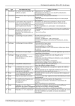
This document contains the following changes:
Change:
addition of information regarding ALM deadband and rate-of-change
calculations
1-4
change in how PIDE responds to the WindupHIn and WindupLIn inputs
1-46
addition of information regarding PIDE algorithms
1-54
correction to TotalTime equation
2-35
correction to real time sampling
B-9
changes to faceplate controls
1
See:
appendix D
Publication 1756-RM006D-EN-P - May 2005
Summary of Changes
2
Notes:
Publication 1756-RM006D-EN-P - May 2005
Instruction Locator
Use this locator to find the reference details about Logix instructions
(the grayed-out instructions are available in other manuals). This
locator also lists which programming languages are available for
the instructions.
Where to Find an
Instruction
1
If the locator lists:
The instruction is documented in:
a page number
this manual
general
Logix5000 Controllers General Instruction Set Reference Manual, 1756-RM003
motion
Logix5000 Controllers Motion Instruction Set Reference Manual, 1756-RM007
phase
Logix5000 Controllers PhaseManager User Manual, LOGIX-UM001
Instruction:
Location:
Languages:
Instruction:
Location:
Languages:
ABL
ASCII Test For Buffer Line
general
relay ladder
structured text
ATN
Arc Tangent
general
relay ladder
function block
ABS
Absolute Value
general
relay ladder
structured text
function block
AVE
File Average
general
relay ladder
general
relay ladder
structured text
AWA
ASCII Write Append
general
ACB
ASCII Chars in Buffer
relay ladder
structured text
general
relay ladder
structured text
AWT
ASCII Write
general
ACL
ASCII Clear Buffer
relay ladder
structured text
general
structured text
BAND
Boolean AND
general
ACOS
Arc Cosine
structured text
function block
general
relay ladder
function block
BNOT
Boolean NOT
general
ACS
Arc Cosine
structured text
function block
general
relay ladder
structured text
function block
BOR
Boolean OR
general
ADD
Add
structured text
function block
BRK
Break
general
relay ladder
AFI
Always False Instruction
general
relay ladder
BSL
Bit Shift Left
general
relay ladder
AHL
ASCII Handshake Lines
general
relay ladder
structured text
BSR
Bit Shift Right
general
relay ladder
ALM
Alarm
1-2
structured text
function block
BTD
Bit Field Distribute
general
relay ladder
AND
Bitwise AND
general
relay ladder
structured text
function block
general
structured text
function block
ARD
ASCII Read
general
relay ladder
structured text
BTDT
Bit Field Distribute with
Target
general
ARL
ASCII Read Line
general
BTR
Message
relay ladder
structured text
general
ASIN
Arc Sine
general
BTW
Message
relay ladder
structured text
general
ASN
Arc Sine
general
BXOR
Boolean Exclusive OR
structured text
function block
general
ATAN
Arc Tangent
general
CLR
Clear
relay ladder
structured text
relay ladder
structured text
structured text
relay ladder
function block
structured text
Publication 1756-RM006D-EN-P - May 2005
Instruction Locator
2
Instruction:
Location:
Languages:
Instruction:
Location:
Languages:
CMP
Compare
general
relay ladder
ESEL
Enhanced Select
4-2
structured text
function block
CONCAT
String Concatenate
general
relay ladder
structured text
EVENT
Trigger Event Task
general
relay ladder
structured text
COP
Copy File
general
relay ladder
structured text
FAL
File Arithmetic and Logic
general
relay ladder
COS
Cosine
general
relay ladder
structured text
function block
FBC
File Bit Comparison
general
relay ladder
relay ladder
general
relay ladder
structured text
FFL
FIFO Load
general
CPS
Synchronous Copy File
relay ladder
general
relay ladder
FFU
FIFO Unload
general
CPT
Compute
general
relay ladder
FGEN
Function Generator
1-34
CTD
Count Down
structured text
function block
general
relay ladder
FIND
Find String
general
CTU
Count Up
relay ladder
structured text
relay ladder
general
structured text
function block
FLL
File Fill
general
CTUD
Count Up/Down
relay ladder
1-7
structured text
function block
FOR
For
general
D2SD
Discrete 2-State Device
1-16
structured text
function block
FRD
Convert to Integer
general
D3SD
Discrete 3-State Device
relay ladder
function block
relay ladder
general
relay ladder
FSC
File Search and Compare
general
DDT
Diagnostic Detect
1-29
structured text
function block
GEQ
Greater than or Equal to
general
DEDT
Deadtime
relay ladder
structured text
function block
DEG
Degrees
general
relay ladder
structured text
function block
GRT
Greater Than
general
relay ladder
structured text
function block
DELETE
String Delete
general
relay ladder
structured text
GSV
Get System Value
general
relay ladder
structured text
DERV
Derivative
3-2
structured text
function block
HLL
High/Low Limit
4-9
structured text
function block
DFF
D Flip-Flop
6-2
structured text
function block
HPF
High Pass Filter
3-6
structured text
function block
DIV
Divide
general
relay ladder
structured text
function block
ICON
Input Wire Connector
B-1
function block
general
relay ladder
structured text
INSERT
Insert String
general
DTOS
DINT to String
relay ladder
structured text
DTR
Data Transitional
general
relay ladder
EOT
End of Transition
general
relay ladder
structured text
EQU
Equal to
general
relay ladder
structured text
function block
Publication 1756-RM006D-EN-P - May 2005
INTG
Integrator
structured text
function block
IOT
Immediate Output
general
relay ladder
structured text
IREF
Input Reference
B-1
function block
JKFF
JK Flip-Flop
6-4
structured text
function block
Instruction Locator
Instruction:
Location:
Languages:
Instruction:
Location:
Languages:
JMP
Jump to Label
general
relay ladder
MAM
Motion Axis Move
motion
relay ladder
structured text
JSR
Jump to Subroutine
general
relay ladder
structured text
function block
MAOC
Motion Arm Output Cam
motion
relay ladder
structured text
general
relay ladder
MAPC
Motion Axis Position Cam
motion
JXR
Jump to External Routine
relay ladder
structured text
general
relay ladder
MAR
Motion Arm Registration
motion
LBL
Label
relay ladder
structured text
3-12
structured text
function block
MAS
Motion Axis Stop
motion
LDL2
Second-Order Lead Lag
relay ladder
structured text
1-38
structured text
function block
MASD
Motion Axis Shutdown
motion
LDLG
Lead-Lag
relay ladder
structured text
general
relay ladder
structured text
function block
MASR
MMotion Axis Shutdown
Reset
motion
LEQ
Less Than or Equal to
relay ladder
structured text
LES
Less Than
general
relay ladder
structured text
function block
MATC
Motion Axis Time Cam
motion
relay ladder
structured text
MAVE
Moving Average
5-2
structured text
function block
MAW
Motion Arm Watch
motion
relay ladder
structured text
MAXC
Maximum Capture
5-6
structured text
function block
MCCP
Motion Calculate Cam
Profile
motion
relay ladder
structured text
MCD
Motion Change Dynamics
motion
relay ladder
structured text
MCR
Master Control Reset
general
relay ladder
LFL
LIFO Load
general
relay ladder
LFU
LIFO Unload
general
LIM
Limit
general
LN
Natural Log
general
relay ladder
structured text
function block
LOG
Log Base 10
general
relay ladder
structured text
function block
LOWER
Lower Case
general
relay ladder
structured text
MDF
Motion Direct Drive Off
motion
relay ladder
structured text
LPF
Low Pass Filter
3-18
structured text
function block
MDO
Motion Direct Drive On
motion
relay ladder
structured text
MAAT
Motion Apply Axis Tuning
motion
relay ladder
structured text
MDOC
Motion Disarm Output Cam
motion
relay ladder
structured text
MAFR
Motion Axis Fault Reset
motion
relay ladder
structured text
MDR
Motion Disarm Registration
motion
relay ladder
structured text
MAG
Motion Axis Gear
motion
relay ladder
structured text
MDW
Motion Disarm Watch
motion
relay ladder
structured text
MAH
Motion Axis Home
motion
relay ladder
structured text
MEQ
Mask Equal to
general
MAHD
Motion Apply Hookup
Diagnostics
motion
relay ladder
structured text
relay ladder
structured text
function block
MGS
Motion Group Stop
motion
relay ladder
structured text
MAJ
Motion Axis Jog
motion
MGSD
Motion Group Shutdown
motion
relay ladder
structured text
relay ladder
relay ladder
function block
relay ladder
structured text
3
Publication 1756-RM006D-EN-P - May 2005
Instruction Locator
4
Instruction:
Location:
Languages:
Instruction:
Location:
Languages:
MGSP
Motion Group Strobe
Position
motion
relay ladder
structured text
NTCH
Notch Filter
3-24
structured text
function block
function block
motion
relay ladder
structured text
OCON
Output Wire Connector
B-1
MGSR
Motion Group Shutdown
Reset
ONS
One Shot
general
relay ladder
MID
Middle String
general
relay ladder
structured text
OR
Bitwise OR
general
MINC
Minimum Capture
5-8
structured text
function block
relay ladder
structured text
function block
function block
general
relay ladder
structured text
function block
OREF
Output Reference
B-1
MOD
Modulo
OSF
One Shot Falling
general
relay ladder
MOV
Move
general
relay ladder
OSFI
One Shot Falling with Input
general
structured text
function block
MRAT
Motion Run Axis Tuning
motion
relay ladder
structured text
OSR
One Shot Rising
general
relay ladder
MRHD
Motion Run Hookup
Diagnostics
motion
relay ladder
structured text
OSRI
One Shot Rising with Input
general
structured text
function block
MRP
Motion Redefine Position
motion
relay ladder
structured text
OTE
Output Energize
general
relay ladder
MSF
Motion Servo Off
motion
relay ladder
structured text
OTL
Output Latch
general
relay ladder
MSG
Message
general
relay ladder
structured text
OTU
Output Unlatch
general
relay ladder
MSO
Motion Servo On
motion
relay ladder
structured text
PATT
Attach to Equipment Phase
phase
relay ladder
structured text
MSTD
Moving Standard Deviation
5-10
structured text
function block
PCLF
Equipment Phase Clear
Failure
phase
relay ladder
structured text
MUL
Multiply
general
relay ladder
structured text
function block
PCMD
Equipment Phase Command
phase
relay ladder
structured text
MUX
Multiplexer
4-12
function block
PDET
Detach from Equipment
Phase
phase
relay ladder
structured text
MVM
Masked Move
general
relay ladder
PFL
Equipment Phase Failure
phase
relay ladder
structured text
MVMT
Masked Move with Target
general
structured text
function block
PI
Proportional + Integral
2-8
structured text
function block
NEG
Negate
general
relay ladder
structured text
function block
PID
Proportional Integral
Derivative
general
relay ladder
structured text
NEQ
Not Equal to
general
relay ladder
structured text
function block
PIDE
Enhanced PID
1-42
structured text
function block
NOP
No Operation
general
relay ladder
PMUL
Pulse Multiplier
2-20
structured text
function block
NOT
Bitwise NOT
general
relay ladder
structured text
function block
POSP
Position Proportional
1-77
structured text
function block
Publication 1756-RM006D-EN-P - May 2005
Instruction Locator
Instruction:
Location:
Languages:
Instruction:
Location:
Languages:
POVR
Equipment Phase Override
Command
phase
relay ladder
structured text
SIN
Sine
general
relay ladder
structured text
function block
PPD
Equipment Phase Paused
phase
relay ladder
structured text
SIZE
Size In Elements
general
relay ladder
structured text
PRNP
Equipment Phase New
Parameters
phase
relay ladder
structured text
SNEG
Selected Negate
4-21
structured text
function block
phase
relay ladder
structured text
SOC
Second-Order Controller
2-38
PSC
Phase State Complete
structured text
function block
relay ladder
phase
relay ladder
structured text
SQI
Sequencer Input
general
PXRQ
Equipment Phase External
Request
SQL
Sequencer Load
general
relay ladder
RAD
Radians
general
relay ladder
structured text
function block
SQO
Sequencer Output
general
relay ladder
RES
Reset
general
relay ladder
SQR
Square Root
general
relay ladder
function block
RESD
Reset Dominant
6-6
structured text
function block
SQRT
Square Root
general
structured text
RET
Return
general
relay ladder
structured text
function block
SRT
File Sort
general
relay ladder
structured text
4-15
structured text
function block
SRTP
Split Range Time
Proportional
1-102
RLIM
Rate Limiter
structured text
function block
RMPS
Ramp/Soak
1-84
structured text
function block
SSUM
Selected Summer
4-23
structured text
function block
RTO
Retentive Timer On
general
relay ladder
SSV
Set System Value
general
relay ladder
structured text
RTOR
Retentive Timer On with
Reset
general
structured text
function block
STD
File Standard Deviation
general
relay ladder
general
relay ladder
structured text
STOD
String To DINT
general
RTOS
REAL to String
relay ladder
structured text
general
relay ladder
structured text
function block
STOR
String To REAL
general
SBR
Subroutine
relay ladder
structured text
SUB
Subtract
general
SCL
Scale
1-98
structured text
function block
relay ladder
structured text
function block
2-28
structured text
function block
SWPB
Swap Byte
general
SCRV
S-Curve
relay ladder
structured text
4-19
function block
TAN
Tangent
general
SEL
Select
relay ladder
structured text
function block
SETD
Set Dominant
6-8
structured text
function block
TND
Temporary End
general
relay ladder
SFP
SFC Pause
general
relay ladder
structured text
TOD
Convert to BCD
general
relay ladder
function block
SFR
SFC Reset
general
relay ladder
structured text
TOF
Timer Off Delay
general
relay ladder
5
Publication 1756-RM006D-EN-P - May 2005
Instruction Locator
6
Instruction:
Location:
Languages:
TOFR
Timer Off Delay with Reset
general
structured text
function block
TON
Timer On Delay
general
relay ladder
TONR
Timer On Delay with Reset
general
structured text
function block
TOT
Totalizer
1-108
structured text
function block
TRN
Truncate
general
relay ladder
function block
TRUNC
Truncate
general
structured text
UID
User Interrupt Disable
general
relay ladder
structured text
UIE
User Interrupt Enable
general
relay ladder
structured text
UPDN
Up/Down Accumulator
2-47
structured text
function block
UPPER
Upper Case
general
relay ladder
structured text
XIC
Examine If Closed
general
relay ladder
XIO
Examine If Open
general
relay ladder
XOR
Bitwise Exclusive OR
general
relay ladder
structured text
function block
XPY
X to the Power of Y
general
relay ladder
structured text
function block
Publication 1756-RM006D-EN-P - May 2005
Preface
This manual is one of several Logix-based instruction documents.
Introduction
Task/Goal:
Documents:
Programming the controller for sequential
applications
Logix5000 Controllers General Instructions Reference Manual,
publication 1756-RM003
Programming the controller for process or drives
applications
Logix5000 Controllers Process Control and Drives Instructions Reference Manual,
publication 1756-RM006
You are here
Programming the controller for motion
applications
Logix5000 Controllers Motion Instructions Reference Manual,
publication 1756-RM007
Importing a text file or tags into a project
Logix5000 Controller Import/Export Reference Manual, publication 1756-RM084
Exporting a project or tags to a text file
Converting a PLC-5 or SLC 500 application to a
Logix5000 application
Logix5550 Controller Converting PLC-5 or SLC 500 Logic to Logix5000 Logic Reference
Manual, publication 1756-RM085
These core documents address the Logix5000 family of controllers:
If you are:
Use this publication:
a new user of a Logix5000 controller
Logix5000 Controllers Quick Start
publication 1756-QS001
This quick start provides a visual, step-by-step overview of the basic steps you need to
complete to get you controller configured and running.
an experienced user of Logix5000 controllers
This design reference provides considerations when planning and implementing a
Logix5000 control system.
Logix5000 Controllers Design
Considerations Reference Manual
publication 1756-QR107
Logix5000 Controllers System Reference
publication 1756-QR107
an experienced user of Logix5000 controllers
This system reference provides a high-level listing of configuration information, controller
features, and instructions (ladder relay, function block diagram, and structured text).
Logix5000 Controllers Common Procedures
publication 1756-PM001
any user of a Logix5000 controller
This common procedures manual explains the common features and functions of all
Logix5000 controllers.
Who Should Use
This Manual
This document provides a programmer with details about each
available instruction for a Logix-based controller. You should already
be familiar with how the Logix-based controller stores and
processes data.
Novice programmers should read all the details about an instruction before
using the instruction. Experienced programmers can refer to the instruction
information to verify details.
1
Publication 1756-RM006D-EN-P - May 2005
Preface
2
Purpose of This Manual
This manual provides a description of each instruction in this format.
This section:
Provides this type of information:
Instruction name
identifies the instruction
defines whether the instruction is an input or an output instruction
Operands
lists all the operands of the instruction
if available in relay ladder, describes the operands
if available in structured text, describes the operands
if available in function block, describes the operands
The pins shown on a default function block are only the default pins. The operands
table lists all the possible pins for a function block.
Instruction structure
lists control status bits and values, if any, of the instruction
Description
describes the instruction’s use
defines any differences when the instruction is enabled and disabled, if appropriate
Arithmetic status flags
defines whether or not the instruction affects arithmetic status flags
see appendix Common Attributes
Fault conditions
defines whether or not the instruction generates minor or major faults
if so, defines the fault type and code
Execution
defines the specifics of how the instruction operates
Example
provides at least one programming example in each available programming language
includes a description explaining each example
The following icons help identify language specific information:
This icon:
Indicates this programming language:
relay ladder
structured text
function block
Publication 1756-RM006D-EN-P - May 2005
Preface
Common Information for
All Instructions
Conventions and
Related Terms
3
The Logix5000 instruction set has some common attributes:
For this information:
See this appendix:
common attributes
appendix Common Attributes defines:
• arithmetic status flags
• data types
• keywords
arrays
appendix Array Concepts defines arrays and explains
how the controller manipulates arrays
function block attributes
appendix Function Block Attributes defines:
• program and operator control
• timing modes
Set and clear
This manual uses set and clear to define the status of bits (booleans) and
values (non-booleans):
This term:
Means:
set
the bit is set to 1 (ON)
a value is set to any non-zero number
clear
the bit is cleared to 0 (OFF)
all the bits in a value are cleared to 0
If an operand or parameter supports more than one data type, the bold data
types indicate optimal data types. An instruction executes faster and requires
less memory if all the operands of the instruction use the same optimal data
type, typically DINT or REAL.
Publication 1756-RM006D-EN-P - May 2005
Preface
4
Relay ladder rung condition
The controller evaluates ladder instructions based on the rung condition
preceding the instruction (rung-condition-in). Based on the rung-condition-in
and the instruction, the controller sets the rung condition following the
instruction (rung-condition-out), which in turn, affects any subsequent
instruction.
input instruction
rung-in
condition
output instruction
rung-out
condition
If the rung-in condition to an input instruction is true, the controller evaluates
the instruction and sets the rung-out condition based on the results of the
instruction. If the instruction evaluates to true, the rung-out condition is true;
if the instruction evaluates to false, the rung-out condition is false.
The controller also prescans instructions. Prescan is a special scan of all
routines in the controller. The controller scans all main routines and
subroutines during prescan, but ignores jumps that could skip the execution of
instructions. The controller executes all FOR loops and subroutine calls. If a
subroutine is called more than once, it is executed each time it is called. The
controller uses prescan of relay ladder instructions to reset non-retentive I/O
and internal values.
During prescan, input values are not current and outputs are not written. The
following conditions generate prescan:
• Toggle from Program to Run mode
• Automatically enter Run mode from a power-up condition.
Prescan does not occur for a program when:
• The program becomes scheduled while the controller is running.
• The program is unscheduled when the controller enters Run mode.
Publication 1756-RM006D-EN-P - May 2005
Preface
5
Function block states
The controller evaluates function block instructions based on the state of
different conditions.
Possible Condition:
Description:
prescan
Prescan for function block routines is the same as for relay ladder routines. The only
difference is that the EnableIn parameter for each function block instruction is cleared
during prescan.
instruction first scan
Instruction first scan refers to the first time an instruction is executed after prescan. The
controller uses instruction first scan to read current inputs and determine the appropriate
state to be in.
instruction first run
Instruction first run refers to the first time the instruction executes with a new instance of a
data structure. The controller uses instruction first run to generate coefficients and other
data stores that do not change for a function block after initial download.
Every function block instruction also includes EnableIn and EnableOut
parameters:
• function block instructions execute normally when EnableIn is set.
• when EnableIn is cleared, the function block instruction either executes
prescan logic, postscan logic, or just skips normal algorithm execution.
• EnableOut mirrors EnableIn, however, if function block execution
detects an overflow condition EnableOut is also cleared.
• function block execution resumes where it left off when EnableIn
toggles from cleared to set. However there are some function block
instructions that specify special functionality, such as re-initialzation,
when EnableIn toggles from cleared to set. For function block
instructions with time base parameters, whenever the timing mode is
Oversample, the instruction always resumes were it left off when
EnableIn toggles from cleared to set.
Publication 1756-RM006D-EN-P - May 2005
Preface
6
If the EnableIn parameter is not wired, the instruction always executes as
normal and EnableIn remains set. If you clear EnableIn, it changes to set the
next time the instruction executes.
IMPORTANT
Publication 1756-RM006D-EN-P - May 2005
When programming in function block, restrict the range of
engineering units to +/-10+/-15 because internal floating point calculations
are done using single precision floating point. Engineering units outside of
this range may result in a loss of accuracy if results approach the limitations
of single precision floating point (+/-10+/-38).
Table of Contents
Chapter 1
Process Control Instructions
(ALM, D2SD, D3SD, DEDT, FGEN,
LDLG, PIDE, POSP, RMPS, SCL,
SRTP, TOT)
i
Introduction . . . . . . . . . . . . . . . . . . . . . . . . . . . . . . . . . . . . . . . . . . . . . 1-1
Alarm (ALM) . . . . . . . . . . . . . . . . . . . . . . . . . . . . . . . . . . . . . . . . . . . . 1-2
High-high to low-low alarm . . . . . . . . . . . . . . . . . . . . . . . . . . . . . 1-4
Rate-of-change alarm. . . . . . . . . . . . . . . . . . . . . . . . . . . . . . . . . . . 1-4
Monitoring the ALM instruction . . . . . . . . . . . . . . . . . . . . . . . . . 1-5
Discrete 2-State Device (D2SD) . . . . . . . . . . . . . . . . . . . . . . . . . . . . . 1-7
Monitoring the D2SD instruction. . . . . . . . . . . . . . . . . . . . . . . . 1-10
Switching between Program control and Operator control . . . 1-12
Commanded state in Program control . . . . . . . . . . . . . . . . . . . . 1-12
Commanded state in Operator control. . . . . . . . . . . . . . . . . . . . 1-13
Hand mode or Override mode . . . . . . . . . . . . . . . . . . . . . . . . . . 1-13
Output state . . . . . . . . . . . . . . . . . . . . . . . . . . . . . . . . . . . . . . . . . 1-14
Fault alarm conditions . . . . . . . . . . . . . . . . . . . . . . . . . . . . . . . . . 1-14
Mode alarm conditions . . . . . . . . . . . . . . . . . . . . . . . . . . . . . . . . 1-15
Discrete 3-State Device (D3SD) . . . . . . . . . . . . . . . . . . . . . . . . . . . . 1-16
Monitoring the D3SD instruction. . . . . . . . . . . . . . . . . . . . . . . . 1-21
Switching between Program control and Operator control . . . 1-24
Commanded state in Program control . . . . . . . . . . . . . . . . . . . . 1-24
Commanded state in Operator control. . . . . . . . . . . . . . . . . . . . 1-25
Hand mode or Override mode . . . . . . . . . . . . . . . . . . . . . . . . . . 1-25
Output state . . . . . . . . . . . . . . . . . . . . . . . . . . . . . . . . . . . . . . . . . 1-27
Fault alarm conditions . . . . . . . . . . . . . . . . . . . . . . . . . . . . . . . . . 1-27
Mode alarm conditions . . . . . . . . . . . . . . . . . . . . . . . . . . . . . . . . 1-28
Deadtime (DEDT). . . . . . . . . . . . . . . . . . . . . . . . . . . . . . . . . . . . . . . 1-29
Servicing the deadtime buffer . . . . . . . . . . . . . . . . . . . . . . . . . . . 1-31
Instruction behavior on InFault transition. . . . . . . . . . . . . . . . . 1-32
Function Generator (FGEN) . . . . . . . . . . . . . . . . . . . . . . . . . . . . . . 1-34
Lead-Lag (LDLG) . . . . . . . . . . . . . . . . . . . . . . . . . . . . . . . . . . . . . . . 1-38
Enhanced PID (PIDE) . . . . . . . . . . . . . . . . . . . . . . . . . . . . . . . . . . . 1-42
Computing CV. . . . . . . . . . . . . . . . . . . . . . . . . . . . . . . . . . . . . . . 1-54
PIDE algorithms . . . . . . . . . . . . . . . . . . . . . . . . . . . . . . . . . . . . . 1-54
Monitoring the PIDE instruction . . . . . . . . . . . . . . . . . . . . . . . . 1-56
Autotuning the PIDE instruction . . . . . . . . . . . . . . . . . . . . . . . . 1-56
Switching between Program control and Operator control . . . 1-62
Operating modes . . . . . . . . . . . . . . . . . . . . . . . . . . . . . . . . . . . . . 1-63
Selecting the setpoint . . . . . . . . . . . . . . . . . . . . . . . . . . . . . . . . . . 1-64
PV high/low alarming . . . . . . . . . . . . . . . . . . . . . . . . . . . . . . . . . 1-66
Converting the PV and SP values to percent . . . . . . . . . . . . . . . 1-68
Deviation high/low alarming . . . . . . . . . . . . . . . . . . . . . . . . . . . 1-69
Zero crossing deadband control . . . . . . . . . . . . . . . . . . . . . . . . . 1-70
Selecting the control variable . . . . . . . . . . . . . . . . . . . . . . . . . . . 1-71
Primary loop control . . . . . . . . . . . . . . . . . . . . . . . . . . . . . . . . . . 1-75
Processing faults. . . . . . . . . . . . . . . . . . . . . . . . . . . . . . . . . . . . . . 1-76
Publication 1756-RM006D-EN-P - May 2005
Table of Contents
ii
Position Proportional (POSP) . . . . . . . . . . . . . . . . . . . . . . . . . . . . . . 1-77
Scaling the position and set point values . . . . . . . . . . . . . . . . . . 1-79
How the POSP instruction uses the internal cycle timer. . . . . . 1-79
Producing output pulses . . . . . . . . . . . . . . . . . . . . . . . . . . . . . . . 1-80
Calculating open and close pulse times. . . . . . . . . . . . . . . . . . . . 1-81
Ramp/Soak (RMPS). . . . . . . . . . . . . . . . . . . . . . . . . . . . . . . . . . . . . . 1-84
Monitoring the RMPS instruction. . . . . . . . . . . . . . . . . . . . . . . . 1-88
Initial mode applied on instruction first scan . . . . . . . . . . . . . . . 1-89
Switching between Program control and Operator control . . . 1-91
Program control . . . . . . . . . . . . . . . . . . . . . . . . . . . . . . . . . . . . . . 1-93
Operator control . . . . . . . . . . . . . . . . . . . . . . . . . . . . . . . . . . . . . 1-94
Executing the ramp/soak profile . . . . . . . . . . . . . . . . . . . . . . . . 1-95
Scale (SCL) . . . . . . . . . . . . . . . . . . . . . . . . . . . . . . . . . . . . . . . . . . . . . 1-98
Alarming. . . . . . . . . . . . . . . . . . . . . . . . . . . . . . . . . . . . . . . . . . . 1-100
Limiting . . . . . . . . . . . . . . . . . . . . . . . . . . . . . . . . . . . . . . . . . . . 1-100
Split Range Time Proportional (SRTP). . . . . . . . . . . . . . . . . . . . . . 1-102
Using the internal cycle timer . . . . . . . . . . . . . . . . . . . . . . . . . . 1-104
Calculating heat and cool times. . . . . . . . . . . . . . . . . . . . . . . . . 1-104
Totalizer (TOT) . . . . . . . . . . . . . . . . . . . . . . . . . . . . . . . . . . . . . . . . 1-108
Monitoring the TOT instruction. . . . . . . . . . . . . . . . . . . . . . . . 1-115
Check for low input cutoff . . . . . . . . . . . . . . . . . . . . . . . . . . . . 1-116
Operating modes . . . . . . . . . . . . . . . . . . . . . . . . . . . . . . . . . . . . 1-117
Resetting the TOT instruction . . . . . . . . . . . . . . . . . . . . . . . . . 1-118
Calculating the totalization . . . . . . . . . . . . . . . . . . . . . . . . . . . . 1-118
Determining if target values have been reached. . . . . . . . . . . . 1-118
Chapter 2
Drives Instructions
(INTG, PI, PMUL, SCRV, SOC,
UPDN)
Publication 1756-RM006D-EN-P - May 2005
Introduction . . . . . . . . . . . . . . . . . . . . . . . . . . . . . . . . . . . . . . . . . . . . . 2-1
Integrator (INTG) . . . . . . . . . . . . . . . . . . . . . . . . . . . . . . . . . . . . . . . . 2-2
Limiting . . . . . . . . . . . . . . . . . . . . . . . . . . . . . . . . . . . . . . . . . . . . . 2-4
Proportional + Integral (PI) . . . . . . . . . . . . . . . . . . . . . . . . . . . . . . . . 2-8
Operating in linear mode. . . . . . . . . . . . . . . . . . . . . . . . . . . . . . . 2-12
Operating in non-linear mode. . . . . . . . . . . . . . . . . . . . . . . . . . . 2-12
Limiting . . . . . . . . . . . . . . . . . . . . . . . . . . . . . . . . . . . . . . . . . . . . 2-15
Pulse Multiplier (PMUL) . . . . . . . . . . . . . . . . . . . . . . . . . . . . . . . . . . 2-20
Calculating the output and remainder. . . . . . . . . . . . . . . . . . . . . 2-22
S-Curve (SCRV) . . . . . . . . . . . . . . . . . . . . . . . . . . . . . . . . . . . . . . . . . 2-28
Calculating output and rate values . . . . . . . . . . . . . . . . . . . . . . . 2-33
Second-Order Controller (SOC) . . . . . . . . . . . . . . . . . . . . . . . . . . . . 2-38
Parameter limitations . . . . . . . . . . . . . . . . . . . . . . . . . . . . . . . . . . 2-41
Limiting . . . . . . . . . . . . . . . . . . . . . . . . . . . . . . . . . . . . . . . . . . . . 2-41
Up/Down Accumulator (UPDN). . . . . . . . . . . . . . . . . . . . . . . . . . . 2-47
Table of Contents
iii
Chapter 3
Filter Instructions
(DERV, HPF, LDL2, LPF, NTCH)
Introduction . . . . . . . . . . . . . . . . . . . . . . . . . . . . . . . . . . . . . . . . . . . . . 3-1
Derivative (DERV) . . . . . . . . . . . . . . . . . . . . . . . . . . . . . . . . . . . . . . . 3-2
High Pass Filter (HPF). . . . . . . . . . . . . . . . . . . . . . . . . . . . . . . . . . . . . 3-6
Second-Order Lead Lag (LDL2) . . . . . . . . . . . . . . . . . . . . . . . . . . . . 3-12
Low Pass Filter (LPF) . . . . . . . . . . . . . . . . . . . . . . . . . . . . . . . . . . . . 3-18
Notch Filter (NTCH). . . . . . . . . . . . . . . . . . . . . . . . . . . . . . . . . . . . . 3-24
Chapter 4
Select/Limit Instructions
(ESEL, HLL, MUX, RLIM, SEL,
SNEG, SSUM)
Introduction . . . . . . . . . . . . . . . . . . . . . . . . . . . . . . . . . . . . . . . . . . . . . 4-1
Enhanced Select (ESEL) . . . . . . . . . . . . . . . . . . . . . . . . . . . . . . . . . . . 4-2
Monitoring the ESEL instruction . . . . . . . . . . . . . . . . . . . . . . . . . 4-6
Switching between Program control and Operator control . . . . 4-8
High/Low Limit (HLL) . . . . . . . . . . . . . . . . . . . . . . . . . . . . . . . . . . . . 4-9
Multiplexer (MUX). . . . . . . . . . . . . . . . . . . . . . . . . . . . . . . . . . . . . . . 4-12
Rate Limiter (RLIM) . . . . . . . . . . . . . . . . . . . . . . . . . . . . . . . . . . . . . 4-15
Select (SEL) . . . . . . . . . . . . . . . . . . . . . . . . . . . . . . . . . . . . . . . . . . . . 4-19
Selected Negate (SNEG) . . . . . . . . . . . . . . . . . . . . . . . . . . . . . . . . . . 4-21
Selected Summer (SSUM) . . . . . . . . . . . . . . . . . . . . . . . . . . . . . . . . . 4-23
Chapter 5
Statistical Instructions
(MAVE, MAXC, MINC, MSTD)
Introduction . . . . . . . . . . . . . . . . . . . . . . . . . . . . . . . . . . . . . . . . . . . . . 5-1
Moving Average (MAVE) . . . . . . . . . . . . . . . . . . . . . . . . . . . . . . . . . . 5-2
Initializing the averaging algorithm. . . . . . . . . . . . . . . . . . . . . . . . 5-4
Maximum Capture (MAXC) . . . . . . . . . . . . . . . . . . . . . . . . . . . . . . . . 5-6
Minimum Capture (MINC) . . . . . . . . . . . . . . . . . . . . . . . . . . . . . . . . . 5-8
Moving Standard Deviation (MSTD) . . . . . . . . . . . . . . . . . . . . . . . . 5-10
Initializing the standard deviation algorithm . . . . . . . . . . . . . . . 5-12
Chapter 6
Move/Logical Instructions
(DFF, JKFF, RESD, SETD)
Introduction . . . . . . . . . . . . . . . . . . . . . . . . . . . . . . . . . . . . . . . . . . . . .
D Flip-Flop (DFF) . . . . . . . . . . . . . . . . . . . . . . . . . . . . . . . . . . . . . . . .
JK Flip-Flop (JKFF). . . . . . . . . . . . . . . . . . . . . . . . . . . . . . . . . . . . . . .
Reset Dominant (RESD) . . . . . . . . . . . . . . . . . . . . . . . . . . . . . . . . . . .
Set Dominant (SETD) . . . . . . . . . . . . . . . . . . . . . . . . . . . . . . . . . . . . .
6-1
6-2
6-4
6-6
6-8
Appendix A
Common Attributes
Introduction . . . . . . . . . . . . . . . . . . . . . . . . . . . . . . . . . . . . . . . . . . . .
Immediate Values. . . . . . . . . . . . . . . . . . . . . . . . . . . . . . . . . . . . . . . .
Data Conversions . . . . . . . . . . . . . . . . . . . . . . . . . . . . . . . . . . . . . . . .
SINT or INT to DINT . . . . . . . . . . . . . . . . . . . . . . . . . . . . . . . .
Integer to REAL . . . . . . . . . . . . . . . . . . . . . . . . . . . . . . . . . . . . .
DINT to SINT or INT . . . . . . . . . . . . . . . . . . . . . . . . . . . . . . . .
REAL to an integer . . . . . . . . . . . . . . . . . . . . . . . . . . . . . . . . . . .
A-1
A-1
A-1
A-3
A-5
A-5
A-6
Publication 1756-RM006D-EN-P - May 2005
Table of Contents
iv
Appendix B
Function Block Attributes
Introduction . . . . . . . . . . . . . . . . . . . . . . . . . . . . . . . . . . . . . . . . . . . . . B-1
Choose the Function Block Elements . . . . . . . . . . . . . . . . . . . . . . . . B-1
Latching Data . . . . . . . . . . . . . . . . . . . . . . . . . . . . . . . . . . . . . . . . . . . . B-2
Order of Execution . . . . . . . . . . . . . . . . . . . . . . . . . . . . . . . . . . . . . . . B-4
Resolve a Loop. . . . . . . . . . . . . . . . . . . . . . . . . . . . . . . . . . . . . . . . B-5
Resolve Data Flow Between Two Blocks. . . . . . . . . . . . . . . . . . . B-6
Create a One Scan Delay . . . . . . . . . . . . . . . . . . . . . . . . . . . . . . . . B-7
Summary. . . . . . . . . . . . . . . . . . . . . . . . . . . . . . . . . . . . . . . . . . . . . B-7
Function Block Responses to Overflow Conditions . . . . . . . . . . . . . B-8
Timing Modes . . . . . . . . . . . . . . . . . . . . . . . . . . . . . . . . . . . . . . . . . . . B-9
Common instruction parameters for timing modes. . . . . . . . . . B-10
Overview of timing modes . . . . . . . . . . . . . . . . . . . . . . . . . . . . . B-12
Program/Operator Control . . . . . . . . . . . . . . . . . . . . . . . . . . . . . . . . B-13
Appendix C
Structured Text Programming
Publication 1756-RM006D-EN-P - May 2005
Introduction . . . . . . . . . . . . . . . . . . . . . . . . . . . . . . . . . . . . . . . . . . . . . C-1
Structured Text Syntax. . . . . . . . . . . . . . . . . . . . . . . . . . . . . . . . . . . . . C-1
Assignments . . . . . . . . . . . . . . . . . . . . . . . . . . . . . . . . . . . . . . . . . . . . . C-3
Specify a non-retentive assignment. . . . . . . . . . . . . . . . . . . . . . . . C-4
Assign an ASCII character to a string. . . . . . . . . . . . . . . . . . . . . . C-5
Expressions. . . . . . . . . . . . . . . . . . . . . . . . . . . . . . . . . . . . . . . . . . . . . . C-5
Use arithmetic operators and functions . . . . . . . . . . . . . . . . . . . . C-7
Use relational operators . . . . . . . . . . . . . . . . . . . . . . . . . . . . . . . . . C-8
Use logical operators . . . . . . . . . . . . . . . . . . . . . . . . . . . . . . . . . . C-10
Use bitwise operators. . . . . . . . . . . . . . . . . . . . . . . . . . . . . . . . . . C-11
Determine the order of execution. . . . . . . . . . . . . . . . . . . . . . . . C-11
Instructions. . . . . . . . . . . . . . . . . . . . . . . . . . . . . . . . . . . . . . . . . . . . . C-12
Constructs. . . . . . . . . . . . . . . . . . . . . . . . . . . . . . . . . . . . . . . . . . . . . . C-13
Some key words are reserved for future use. . . . . . . . . . . . . . . . C-13
IF...THEN . . . . . . . . . . . . . . . . . . . . . . . . . . . . . . . . . . . . . . . . . . . . . C-14
CASE...OF . . . . . . . . . . . . . . . . . . . . . . . . . . . . . . . . . . . . . . . . . . . . . C-17
FOR…DO . . . . . . . . . . . . . . . . . . . . . . . . . . . . . . . . . . . . . . . . . . . . . C-19
WHILE…DO . . . . . . . . . . . . . . . . . . . . . . . . . . . . . . . . . . . . . . . . . . C-22
REPEAT…UNTIL . . . . . . . . . . . . . . . . . . . . . . . . . . . . . . . . . . . . . . C-25
Comments . . . . . . . . . . . . . . . . . . . . . . . . . . . . . . . . . . . . . . . . . . . . . C-28
Table of Contents
v
Appendix D
Function Block Faceplate Controls Introduction . . . . . . . . . . . . . . . . . . . . . . . . . . . . . . . . . . . . . . . . . . . . D-1
Configuring general properties . . . . . . . . . . . . . . . . . . . . . . . . . . D-2
Configuring display properties . . . . . . . . . . . . . . . . . . . . . . . . . . D-3
Configuring font properties. . . . . . . . . . . . . . . . . . . . . . . . . . . . . D-4
Configuring location properties . . . . . . . . . . . . . . . . . . . . . . . . . D-5
ALM Control . . . . . . . . . . . . . . . . . . . . . . . . . . . . . . . . . . . . . . . . . . . D-6
ESEL Control. . . . . . . . . . . . . . . . . . . . . . . . . . . . . . . . . . . . . . . . . . . D-8
TOT Control . . . . . . . . . . . . . . . . . . . . . . . . . . . . . . . . . . . . . . . . . . . D-9
RMPS Control . . . . . . . . . . . . . . . . . . . . . . . . . . . . . . . . . . . . . . . . . D-11
D2SD Control . . . . . . . . . . . . . . . . . . . . . . . . . . . . . . . . . . . . . . . . . D-14
D3SD Control . . . . . . . . . . . . . . . . . . . . . . . . . . . . . . . . . . . . . . . . . D-16
PIDE Control. . . . . . . . . . . . . . . . . . . . . . . . . . . . . . . . . . . . . . . . . . D-18
Publication 1756-RM006D-EN-P - May 2005
Table of Contents
vi
Notes:
Publication 1756-RM006D-EN-P - May 2005
Chapter
1
Process Control Instructions
(ALM, D2SD, D3SD, DEDT, FGEN, LDLG, PIDE, POSP, RMPS, SCL,
SRTP, TOT)
Introduction
1
These process control instruction are available:
If you want to:
Use this instruction:
provide alarming for any analog signal.
Alarm (ALM)
structured text
function block
1-2
control discrete devices, such as solenoid
valves, pumps, and motors, that have only two
possible states such as on/off, open/closed,
etc.
Discrete 2-State Device
(D2SD)
structured text
function block
1-7
control discrete devices, such as high/low/off
Discrete 3-State Device
feeders, that have three possible states such as (D3SD)
fast/slow/off, forward/stop/reverse, etc.
structured text
function block
1-16
perform a delay of a single input. You select the
amount of deadtime delay.
Deadtime (DEDT)
structured text
function block
1-29
convert an input based on a piece-wise
linear function.
Function Generator (FGEN)
structured text
function block
1-34
provide a phase lead-lag compensation for an
input signal.
Lead-Lag (LDLG)
structured text
function block
1-38
regulate an analog output to maintain a process Enhanced PID (PIDE)
variable at a certain setpoint using a PID
algorithm.
structured text
function block
1-42
raise/lower or open/close a device, such as a
motor-operated valve, by pulsing open or close
contacts.
Position Proportional
(POSP)
structured text
function block
1-77
provide for alternating ramp and soak periods
to follow a temperature profile.
Ramp/Soak (RMPS)
structured text
function block
1-84
convert an unscaled input value to a floating
point value in engineering units.
Scale (SCL)
structured text
function block
1-98
take the 0-100% output of a PID loop and drive Split Range Time
heating and cooling digital output contacts with Proportional (SRTP)
a periodic pulse.
structured text
function block
1-102
provide a time-scaled accumulation of an
analog input value, such as a volumetric flow.
structured text
function block
1-108
Totalizer (TOT)
Available in these languages:
See page:
Publication 1756-RM006D-EN-P - May 2005
1-2
Process Control Instructions (ALM, D2SD, D3SD, DEDT, FGEN, LDLG, PIDE, POSP, RMPS, SCL, SRTP, TOT)
The ALM instruction provides alarming for any analog signal.
Alarm (ALM)
Operands:
ALM(ALM_tag);
Structured Text
Operand:
Type:
Format:
Description:
ALM tag
ALARM
structure
ALM structure
Function Block
Operand:
Type:
Format:
Description:
ALM tag
ALARM
structure
ALM structure
ALARM Structure
Input Parameter:
Data Type:
Description:
EnableIn
BOOL
Function Block:
If cleared, the instruction does not execute and outputs are not updated.
If set, the instruction executes.
Default is set.
Structured Text:
No effect. The instruction always executes.
In
REAL
The analog signal input.
Valid = any float
Default = 0.0
HHLimit
REAL
The high-high alarm limit for the input.
Valid = any real value
Default = maximum positive value
HLimit
REAL
The high alarm limit for the input.
Valid = any real value
Default = maximum positive value
LLimit
REAL
The low alarm limit for the input.
Valid = any real value.
Default = maximum negative value
LLLimit
REAL
The low-low alarm limit for the input.
Valid = any real value
Default = maximum negative value
Deadband
REAL
The alarm deadband for the high-high to low-low limits.
Valid = any real value ≥ 0.0
Default = 0.0
Publication 1756-RM006D-EN-P - May 2005
Process Control Instructions (ALM, D2SD, D3SD, DEDT, FGEN, LDLG, PIDE, POSP, RMPS, SCL, SRTP, TOT)
1-3
Input Parameter:
Data Type:
Description:
ROCPosLimit
REAL
The rate-of-change alarm limit in units per second for a positive (increasing) change in
the input. Set ROCPosLimit = 0 to disable ROC positive alarming. If invalid, the instruction
assumes a value of 0.0 and sets the appropriate bit in Status.
Valid = any real value ≥ 0.0
Default = 0.0
ROCNegLimit
REAL
The rate-of-change alarm limit in units per second for a negative (decreasing) change in the
input. Set ROCPNegLimit = 0 to disable ROC negative alarming. If invalid, the instruction
assumes a value of 0.0 and sets the appropriate bit in Status.
Valid = any real value ≥ 0.0
Default = 0.0
ROCPeriod
REAL
The time period used to evaluate the rate-of-change alarms (in seconds). Set ROCPeriod = 0
to disable ROC alarming and set the output ROC to zero. If invalid, the instruction assumes a
value of 0.0 and sets the appropriate bit in Status.
Valid = any real value ≥ 0.0
Default = 0.0
Output Parameter:
Data Type:
Description:
EnableOut
BOOL
Enable output.
HHAlarm
BOOL
The high-high alarm indicator.
Default = false
HAlarm
BOOL
The high alarm indicator.
Default = false
LAlarm
BOOL
The low alarm indicator.
Default = false
LLAlarm
BOOL
The low-low alarm indicator.
Default = false
ROCPosAlarm
BOOL
The rate-of-change positive alarm indicator.
Default = false
ROCNegAlarm
BOOL
The rate-of-change negative alarm indicator.
Default = false
ROC
REAL
The rate-of-change output. Arithmetic status flags are set for this output.
Status
DINT
Status of the function block.
InstructFault (Status.0) BOOL
The instruction detected one of the following execution errors. This is not a minor or major
controller error. Check the remaining status bits to determine what occurred.
DeadbandInv
(Status.1)
BOOL
Invalid Deadband value.
ROCPosLimitInv
(Status.2)
BOOL
Invalid ROCPosLimit value.
ROCNegLimitInv
(Status.3)
BOOL
Invalid ROCNegLimit value.
ROCPeriodInv
(Status.4)
BOOL
Invalid ROCPeriod value.
Publication 1756-RM006D-EN-P - May 2005
1-4
Process Control Instructions (ALM, D2SD, D3SD, DEDT, FGEN, LDLG, PIDE, POSP, RMPS, SCL, SRTP, TOT)
Description: The ALM instruction provides alarm indicators for high-high, high, low,
low-low, rate-of-change positive, and rate-of-change negative. An alarm
deadband is available for the high-high to low-low alarms. A user defined
period for performing rate-of-change alarming is also available.
High-high to low-low alarm
The high-high and low-low alarm algorithms compare the input to the alarm
limit and the alarm limit plus or minus the deadband.
In ≥ HHLim
In ≥ HLim
HHAlarm
false
HHAlarm
true
HAlarm
false
In < (HHLim − Deadband)
HAlarm
true
In < (HLim − Deadband)
In ≤ LLLim
In ≤ LLim
LLAlarm
false
LLAlarm
true
LAlarm
false
In > (LLLim + Deadband)
LAlarm
true
In > (LLim + Deadband)
Rate-of-change alarm
The rate-of-change (ROC) alarm compares the change of the input over the
ROCPeriod to the rate-of-change limits. The ROCPeriod provides a type of
deadband for the rate-of-change alarm. For example, define an ROC alarm
limit of 2°F/second with a period of execution of 100 ms. If you use an analog
input module with a resolution of 1°F, every time the input value changes, an
ROC alarm is generated because the instruction calculates an effective rate of
10°F/second. However, enter an ROCPeriod of 1 sec and the instruction only
generates an alarm if the rate truly exceeds the 2°F/second limit.
The ROC alarm calculates the rate-of-change as:
( Now ) – In ( EndofpreviousROCPeriod -)
ROC = In
-----------------------------------------------------------------------------------------------------------ROCPeriod
Publication 1756-RM006D-EN-P - May 2005
Process Control Instructions (ALM, D2SD, D3SD, DEDT, FGEN, LDLG, PIDE, POSP, RMPS, SCL, SRTP, TOT)
1-5
The instruction performs this calculation when the ROCPeriod expires. Once
the instruction calculates the ROC, it determines alarms as:
ROC ≥ ROCPosLim
ROCPosAlarm
false
ROCPosAlarm
true
ROC < ROCPosLim
ROC ≤ −ROCNegLim
ROCPNegAlarm
false
ROCPNegAlarm
true
ROC > −ROCNegLim
Monitoring the ALM instruction
There is an operator faceplate available for the ALM instruction. For more
information, see appendix Function Block Faceplate Controls.
Arithmetic Status Flags: Arithmetic status flags are set for the ROC output.
Fault Conditions: none
Execution:
Condition:
Function Block Action:
Structured Text Action:
prescan
No action taken.
No action taken.
instruction first scan
All alarm outputs are cleared.
The elapsed time accumulator is cleared.
All alarm outputs are cleared.
The elapsed time accumulator is cleared.
instruction first run
All alarm outputs are cleared.
The elapsed time accumulator is cleared.
All alarm outputs are cleared.
The elapsed time accumulator is cleared.
EnableIn is cleared
EnableOut is cleared, the instruction does nothing,
and the outputs are not updated.
na
EnableIn is set
The instruction executes.
EnableOut is set.
EnableIn is always set.
The instruction executes.
postscan
No action taken.
No action taken.
Publication 1756-RM006D-EN-P - May 2005
1-6
Process Control Instructions (ALM, D2SD, D3SD, DEDT, FGEN, LDLG, PIDE, POSP, RMPS, SCL, SRTP, TOT)
Example: The ALM instruction is typically used either with analog input modules (such
as 1771 I/O modules) that do not support on-board alarming or to generate
alarms on a calculated variable. In this example, an analog input from a
1771-IFE module is first scaled to engineering units using the SCL instruction.
The Out of the SCL instruction is an input to the ALM instruction to
determine whether to set an alarm. The resulting alarm output parameters
could then be used in your program and/or viewed on an operator interface
display.
Structured Text
SCL_01.In := Input0From1771IFE;
SCL(SCL_01);
ALM_01.In := SCL_01.Out;
ALARM(ALM_01);
Function Block
Publication 1756-RM006D-EN-P - May 2005
Process Control Instructions (ALM, D2SD, D3SD, DEDT, FGEN, LDLG, PIDE, POSP, RMPS, SCL, SRTP, TOT)
Discrete 2-State Device
(D2SD)
1-7
The D2SD instruction controls a discrete device which has only two possible
states such as on/off, open/closed, etc.
Operands:
D2SD(D2SD_tag);
Structured Text
Operand:
Type:
Format:
Description:
D2SD tag
DISCRETE_2STATE
structure
D2SD structure
Function Block
Operand:
Type:
Format:
Description:
D2SD tag
DISCRETE_2STATE
structure
D2SD structure
DISCRETE_2STATE Structure
Input Parameter:
Data Type:
Description:
EnableIn
BOOL
Function Block:
If cleared, the instruction does not execute and outputs are not updated.
If set, the instruction executes.
Default is set.
Structured Text:
No effect. The instruction executes.
ProgCommand
BOOL
Used to determine CommandStatus when the device is in Program control. When set, the
device is commanded to the 1 state; when cleared, the device is commanded to the 0 state.
Default is cleared.
Oper0Req
BOOL
Operator state 0 request. Set by the operator interface to place the device in the 0 state
when the device is in Operator control.
Default is cleared.
Oper1Req
BOOL
Operator state 1 request. Set by the operator interface to place the device in the 1 state
when the device is in Operator control.
Default is cleared.
State0Perm
BOOL
State 0 permissive. Unless in Hand or Override mode, this input must be set for the device to
enter the 0 state. This input has no effect for a device already in the 0 state.
Default is set.
Publication 1756-RM006D-EN-P - May 2005
1-8
Process Control Instructions (ALM, D2SD, D3SD, DEDT, FGEN, LDLG, PIDE, POSP, RMPS, SCL, SRTP, TOT)
Input Parameter:
Data Type:
Description:
State1Perm
BOOL
State 1 permissive. Unless in the Hand or Override mode, this input must be set for the
device to enter the 1 state. This input has no effect for a device already in the 1 state.
Default is set.
FB0
BOOL
The first feedback input available to the D2SD instruction.
Default is cleared.
FB1
BOOL
The second feedback input available to the D2SD instruction.
Default is cleared.
HandFB
BOOL
Hand feedback input. This input is from a field hand/off/auto station and it shows the
requested state of the field device. When set, the field device is being requested to enter the
1 state; when cleared, the field device is being requested to enter the 0 state.
Default is cleared.
FaultTime
REAL
Fault time value. Configure the value in seconds of the time to allow the device to reach a
newly commanded state. Set FaultTime = 0 to disable the fault timer. If this value is invalid,
the instruction assumes a value of zero and sets the appropriate bit in Status.
Valid = any float ≥ 0.0
Default = 0.0
FaultAlarmLatch
BOOL
Fault alarm latch input. When set and FaultAlarm is set, latch FaultAlarm. To unlatch
FaultAlarm set FaultAlmUnlatch or clear FaultAlarmLatch.
Default is cleared.
FaultAlmUnLatch
BOOL
Fault alarm unlatch input. Set FaultAlmUnLatch when FaultAlarmLatch is set to unlatch
FaultAlarm. The instruction clears this input.
Default is cleared.
OverrideOnInit
BOOL
Override on initialization request. If this bit is set, then during instruction first scan, the
2-state device is placed in Operator control, Override is set, and Hand is cleared. If
ProgHandReq is set, then Override is cleared and Hand is set.
Default is cleared.
OverrideOnFault
BOOL
Override on fault request. Set OverrideOnFault if the device should go to Override mode and
enter the OverrideState on a fault alarm. After the fault alarm is removed, the 2-state device
is placed in Operator control.
Default is cleared.
OutReverse
BOOL
Reverse default out state. The default state of Out is cleared when commanded to state 0,
and set when commanded to state 1. When OutReverse is set, Out is set when commanded
to state 0, and cleared when commanded to state 1.
Default is cleared.
OverrideState
BOOL
Override state input. Configure this value to specify the state of the device when the device
is in Override mode. Set indicates that the device should go to the 1 state; cleared indicates
that the device should go to the 0 state.
Default is cleared.
FB0State0
BOOL
Feedback 0 state 0 input. Configure the state of the FB0 when the device is in the 0 state.
Default is cleared.
FB0State1
BOOL
Feedback 0 state 1 input. Configure the state of the FB0 when the device is in the 1 state.
Default is cleared.
FB1State0
BOOL
Feedback 1 state 0 input. Configure the state of the FB1 when the device is in the 0 state.
Default is cleared.
FB1State1
BOOL
Feedback 1 state 1 input. Configure the state of the FB1 when the device is in the 1 state.
Default is cleared.
Publication 1756-RM006D-EN-P - May 2005
Process Control Instructions (ALM, D2SD, D3SD, DEDT, FGEN, LDLG, PIDE, POSP, RMPS, SCL, SRTP, TOT)
1-9
Input Parameter:
Data Type:
Description:
ProgProgReq
BOOL
Program program request. Set by the user program to request Program control. Ignored if
ProgOperReq is set. Holding this set and ProgOperReq cleared locks the instruction into
Program control.
Default is cleared.
ProgOperReq
BOOL
Program operator request. Set by the user program to request Operator control. Holding this
set locks the instruction into Operator control.
Default is cleared.
ProgOverrideReq
BOOL
Program override request. Set by the user program to request the device to enter Override
mode. Ignored if ProgHandReq is set.
Default is cleared.
ProgHandReq
BOOL
Program hand request. Set by the user program to request the device to enter Hand mode.
Default is cleared.
OperProgReq
BOOL
Operator program request. Set by the operator interface to request Program control. The
instruction clears this input.
Default is cleared.
OperOperReq
BOOL
Operator operator request. Set by the operator interface to request Operator control. The
instruction clears this input.
Default is cleared.
ProgValueReset
BOOL
Reset program control values. When set, all the program request inputs are cleared each
execution of the instruction.
Default is cleared.
Output Parameter:
Data Type:
Description:
EnableOut
BOOL
Enable output.
Out
BOOL
The output of the 2-state instruction.
Device0State
BOOL
Device 0 state output. Set when the device is commanded to the 0 state and the feedbacks
indicate the device really is in the 0 state.
Device1State
BOOL
Device 1 state output. Set when the device is commanded to the 1 state and the feedbacks
indicate the device really is in the 1 state.
CommandStatus
BOOL
Command status output. Set when the device is being commanded to the 1 state and cleared
when the device is being commanded to the 0 state.
FaultAlarm
BOOL
Fault alarm output. Set if the device was commanded to a new state and the FaultTime has
expired without the feedbacks indicating that the new state has actually been reached. Also
set if, after reaching a commanded state, the feedbacks suddenly indicate that the device is
no longer in the commanded state.
ModeAlarm
BOOL
Mode alarm output. Set if the device is in Operator control and a program command changes
to a state which is different from the state currently commanded by the operator. This alarm
is intended as a reminder that a device was left in Operator control.
ProgOper
BOOL
Program/Operator control indicator. Set when in Program control. Cleared when in
Operator control.
Override
BOOL
Override mode. Set when the device is in the Override mode.
Hand
BOOL
Hand mode. Set when the device is in the Hand mode.
Status
DINT
Status of the function block.
Publication 1756-RM006D-EN-P - May 2005
1-10
Process Control Instructions (ALM, D2SD, D3SD, DEDT, FGEN, LDLG, PIDE, POSP, RMPS, SCL, SRTP, TOT)
Output Parameter:
Data Type:
Description:
InstructFault (Status.0) BOOL
The instruction detected one of the following execution errors. This is not a minor or major
controller error. Check the remaining status bits to determine what occurred.
FaultTimeInv (Status.1) BOOL
Invalid FaultTime value. The instruction sets FaultTime = 0.
OperReqInv (Status.2)
Both operator state request bits are set.
BOOL
Description: The D2SD instruction controls a discrete device which has only two possible
states such as on/off, open/closed, etc. Typical discrete devices of this nature
include motors, pumps, and solenoid valves.
Monitoring the D2SD instruction
There is an operator faceplate available for the D2SD instruction. For more
information, see appendix Function Block Faceplate Controls.
Arithmetic Status Flags: Arithmetic status flags are not affected.
Fault Conditions: none
Execution:
Condition:
Function Block Action:
Structured Text Action:
prescan
No action taken.
No action taken.
instruction first scan
The fault timer is cleared.
ModeAlarm is cleared.
All the operator request inputs are cleared.
If ProgValueReset is set, all the program request inputs are cleared.
When OverrideOnInit is set, ProgOper is cleared (Operator control).
If ProgHandReq is cleared and OverrideOnInit is set, clear Hand and set Override (Override mode).
If ProgHandReq is set, set Hand and clear Override (Hand mode).
instruction first run
ProgOper and CommandStatus are cleared.
ProgOper and CommandStatus are cleared.
EnableIn is cleared
EnableOut is cleared, the instruction does nothing,
and the outputs are not updated.
na
EnableIn is set
The instruction executes.
EnableOut is set.
EnableIn is always set.
The instruction executes.
postscan
No action taken.
No action taken.
Publication 1756-RM006D-EN-P - May 2005
Process Control Instructions (ALM, D2SD, D3SD, DEDT, FGEN, LDLG, PIDE, POSP, RMPS, SCL, SRTP, TOT)
1-11
Example: The D2SD instruction is typically used to control on-off or open-close devices
such as pumps or solenoid valves. In this example, the D2SD instruction
controls a solenoid valve adding corn syrup to a batch tank. As long as the
D2SD instruction is in Program control, the valve opens when the AddSyrup
input is set. The operator can also take Operator control of the valve to open
or close it if necessary. The solenoid valve in this example has limit switches
that indicate when the valve is fully closed or opened. These switches are wired
into the FB0 and FB1 feedback inputs. This allows the D2SD instruction to
generate a FaultAlarm if the solenoid valve does not reach the commanded
state within the configured FaultTime.
Structured Text
SyrupController.ProgCommand := AddSyrup;
SyrupController.FB0 := SyrupValveClosedLimitSwitch;
SyrupController.FB1 := SyrupValveOpenedLimitSwitch;
D2SD(SyrupController);
SyrupValve := SyrupController.Out;
Function Block
Publication 1756-RM006D-EN-P - May 2005
1-12
Process Control Instructions (ALM, D2SD, D3SD, DEDT, FGEN, LDLG, PIDE, POSP, RMPS, SCL, SRTP, TOT)
Switching between Program control and Operator control
The following diagram shows how the D2SD instruction changes between
Program control and Operator control.
OperOperReq is set when ProgProgReq is cleared
ProgOperReq is set (1)
Override transitions from set to cleared and Hand is cleared
Program Control
Operator Control
Hand transitions from set to cleared and Override is cleared
ProgProgReq is set when ProgOperReq is cleared
OperProgReq is set when ProgOperReq is cleared and
OperOperReq is cleared
(1) The instruction remains in Operator control mode when ProgOperReq is set.
For more information on program and operator control, see page B-13.
Commanded state in Program control
The following diagram illustrates how the D2SD instruction operates when in
Program control.
ProgCommand is cleared
State0Perm is set
Set Command Status
Publication 1756-RM006D-EN-P - May 2005
ProgCommand is set
State1Perm is set
Clear Command Status
Process Control Instructions (ALM, D2SD, D3SD, DEDT, FGEN, LDLG, PIDE, POSP, RMPS, SCL, SRTP, TOT)
1-13
Commanded state in Operator control
The following diagram illustrates how the D2SD instruction operates when in
Operator control.
Oper0Req is set
State0Perm is set
Set Command Status
Oper1Req is set
State1Perm is set
Cleared Command Status
If both Oper0Req and Oper1Req are set:
• the instruction sets the appropriate bit in Status
• if Override and Hand are cleared, the instruction holds the
previous state.
After every instruction execution, the instruction:
• clears all the operator request inputs
• if ProgValueReset is set, clears all the program request inputs
Hand mode or Override mode
The following table describes how the D2SD instruction determines whether
to operate in Hand or Override mode
ProgHandReq:
ProgOverrideReq:
FaultAlarm and
OverrideOnFault:
Description:
set
either
either
Hand mode
Hand is set
Override is cleared
cleared
set
either
Override mode
Hand is cleared
Override is set
cleared
either
set
Override mode
Hand is cleared
Override is set
When the instruction is in Override mode, CommandStatus = OverrideState
When the instruction is in Hand mode, CommandStatus = HandFB
Publication 1756-RM006D-EN-P - May 2005
1-14
Process Control Instructions (ALM, D2SD, D3SD, DEDT, FGEN, LDLG, PIDE, POSP, RMPS, SCL, SRTP, TOT)
Output state
The D2SD output state is based on the state of the command status.
CommandStatus:
Output state:
cleared
if OutReverse is cleared, Out is cleared
if OutReverse is set, Out is set
set
if OutReverse is cleared, Out is set
if OutReverse is set, Out is cleared
cleared and
FB0 = FB0State0 and
FB1 = FB1State0
the fault timer is stopped and cleared
Device0State is set
set and
FB0 = FB0State1 and
FB1 = FB1State1
the fault timer is stopped and cleared
Device1State is set
Fault alarm conditions
The D2SD instruction checks for these fault alarm conditions.
Fault alarm condition resulting from:
Rules:
device state was commanded to change, but the feedback Start the fault timer when CommandStatusn ≠ CommandStatusn-1
did not indicate that the desired state was actually
Set FaultAlarm when fault timer is done and FaultTime > 0.0
reached within the FaultTime.
the device unexpectedly leaving a state (according to the
feedback) without being commanded to.
Set FaultAlarm when the fault timer is not timing and one of the following
conditions is satisfied:
CommandStatus is cleared and Device0State is cleared
CommandStatus is set and Device1State is cleared
FaultAlarm is cleared if one of the following conditions is met:
• CommandStatus is cleared and Device0State is set
• CommandStatus is set and Device1State is set
• FaultTime ≤ 0
FaultAlarm cannot be cleared when FaultAlarmLatch is set, unless
FaultAlmUnlatch is set and no fault is present.
Publication 1756-RM006D-EN-P - May 2005
Process Control Instructions (ALM, D2SD, D3SD, DEDT, FGEN, LDLG, PIDE, POSP, RMPS, SCL, SRTP, TOT)
1-15
Mode alarm conditions
The mode alarm reminds an operator that a device has been left in operator
control. The mode alarm only turns on when in operator control mode, the
program tries to change the state of the device from the operator’s
commanded state. The alarm does not turn on if an operator places a device in
operator mode and changes the state. The D2SD instruction checks for mode
alarm conditions, using these rules.
ModeAlarm:
When:
set
ProgCommandn ≠ ProgCommandn-1 and
ProgCommandn ≠ CommandStatus
cleared
ProgCommand = CommandStatus or
the device is in override, hand, or program
control mode
Publication 1756-RM006D-EN-P - May 2005
1-16
Process Control Instructions (ALM, D2SD, D3SD, DEDT, FGEN, LDLG, PIDE, POSP, RMPS, SCL, SRTP, TOT)
Discrete 3-State Device
(D3SD)
The D3SD instruction controls a discrete device having three possible states
such as fast/slow/off, forward/stop/reverse, etc.
Operands:
D3SD(D3SD_tag);
Structured Text
Operand:
Type:
Format:
Description:
D3SD tag
DISCRETE_3STATE
structure
D3SD structure
Function Block
Operand:
Type:
Format:
Description:
D3SD tag
DISCRETE_3STATE
structure
D2SD structure
DISCRETE_3STATE Structure
Input Parameter:
Data Type:
Description:
EnableIn
BOOL
Function Block:
If cleared, the instruction does not execute and outputs are not updated.
If set, the instruction executes.
Default is set.
Structured Text:
No effect. The instruction executes.
Prog0Command
BOOL
Program state 0 command. This input determines the device state when the device is in
Program control. If set, the device is commanded to the 0 state.
Default is cleared.
Prog1Command
BOOL
Program state 1 command. This input determines the device state when the device is in
Program control. If set, the device is commanded to the 1 state.
Default is cleared.
Prog2Command
BOOL
Program state 2 command. This input determines the device state when the device is in
Program control. If set, the device is commanded to the 2 state.
Default is cleared.
Publication 1756-RM006D-EN-P - May 2005
Process Control Instructions (ALM, D2SD, D3SD, DEDT, FGEN, LDLG, PIDE, POSP, RMPS, SCL, SRTP, TOT)
1-17
Input Parameter:
Data Type:
Description:
Oper0Req
BOOL
Operator state 0 request. Set by the operator interface to place the device into the 0 state
when the device is in Operator control.
Default is cleared.
Oper1Req
BOOL
Operator state 1 request. Set by the operator interface to place the device into the 1 state
when the device is in Operator control.
Default is cleared.
Oper2Req
BOOL
Operator state 2 request. Set by the operator interface to place the device into the 2 state
when the device is in Operator control.
Default is cleared.
State0Perm
BOOL
State 0 permissive. Unless in Hand or Override mode, this input must be set for the device to
enter the 0 state. This input has no effect if the device is already in the 0 state.
Default is set.
State1Perm
BOOL
State 1 permissive. Unless in Hand or Override mode, this input must be set for the device to
enter the 1 state. This input has no effect if the device is already in the 1 state.
Default is set.
State2Perm
BOOL
State 2 permissive. Unless in Hand or Override mode, this input must be set for the device to
enter the 2 state. This input has no effect if the device is already in the 2 state.
Default is set.
FB0
BOOL
The first feedback input available to the instruction.
Default is cleared.
FB1
BOOL
The second feedback input available to the instruction.
Default is cleared.
FB2
BOOL
The third feedback input available to the instruction.
Default is cleared.
FB3
BOOL
The fourth feedback input available to the instruction.
Default is cleared.
HandFB0
BOOL
Hand feedback state 0. This input from a field hand/off/auto station shows the requested
state of the field device. Set indicates that the field device is being requested to enter the
0 state; cleared indicates that the field device is being requested to enter some other state.
Default is cleared.
HandFB1
BOOL
Hand feedback state 1. This input from a field hand/off/auto station shows the requested
state of the field device. Set indicates that the field device is being requested to enter the
1 state; cleared indicates that the field device is being requested to enter some other state.
Default is cleared.
HandFB2
BOOL
Hand feedback state 2. This input from a field hand/off/auto station shows the requested
state of the field device. Set indicates that the field device is being requested to enter the
2 state; cleared indicates that the field device is being requested to enter some other state.
Default is cleared.
FaultTime
REAL
Fault time value. Configure the value in seconds of the time to allow the device to reach a
newly commanded state. Set FaultTime = 0 to disable the fault timer. If this value is invalid,
the instruction assumes a value of zero and sets the appropriate bit in Status.
Valid = any float ≥ 0.0
Default = 0.0
FaultAlarmLatch
BOOL
Fault alarm latch input. When set and FaultAlarm is set, latch FaultAlarm. To unlatch
FaultAlarm, set FaultAlmUnlatch or clear FaultAlarmLatch.
Default is cleared.
Publication 1756-RM006D-EN-P - May 2005
1-18
Process Control Instructions (ALM, D2SD, D3SD, DEDT, FGEN, LDLG, PIDE, POSP, RMPS, SCL, SRTP, TOT)
Input Parameter:
Data Type:
Description:
FaultAlmUnLatch
BOOL
Fault alarm unlatch input. Set this input when FaultAlarmLatch is set to unlatch FaultAlarm.
The instruction clears this input.
Default is cleared.
OverrideOnInit
BOOL
Override on initialization request. If this bit is set, then during instruction first scan, the
instruction is placed in Operator control with Override set and Hand cleared. If ProgHandReq
is set, then Override is cleared and Hand is set.
Default is cleared.
OverrideOnFault
BOOL
Override on fault request. Set this value if the device should go to Override mode and enter
the OverrideState on a fault alarm. After the fault alarm is removed, the instruction is
placed in Operator control.
Default is cleared.
Out0State0
BOOL
Output 0 state 0 input. This value determines the value of Output0 when the device is in the
0 state.
Default is cleared.
Out0State1
BOOL
Output 0 state 1 input. This value determines the value of Output0 when the device is in the
1 state.
Default is cleared.
Out0State2
BOOL
Output 0 state 2 input. This value determines the value of Output0 when the device is in the
2 state.
Default is cleared.
Out1State0
BOOL
Output 1 state 0 input. This value determines the value of Output1 when the device is in the
0 state.
Default is cleared.
Out1State1
BOOL
Output 1 state 1 input. This value determines the value of Output1 when the device is in the
1 state.
Default is cleared.
Out1State2
BOOL
Output 1 state 2 input. This value determines the value of Output1 when the device is in the
2 state.
Default is cleared.
Out2State0
BOOL
Output 2 state 0 input. This value determines the value of Output2 when the device is in the
0 state.
Default is cleared.
Out2State1
BOOL
Output 2 state 1 input. This value determines the value of Output2 when the device is in the
1 state.
Default is cleared.
Out2State2
BOOL
Output 2 state 2 input. This value determines the value of Output2 when the device is in the
2 state.
Default is cleared.
OverrideState
DINT
Override state input. Set this input to indicate the state of the device when in Override mode.
Value:
Indicates:
2
device should go to the 2 state
1
device should go to the 1 state
0
device should go to the 0 state
An invalid value sets the appropriate bit in Status and prevents the instruction from entering
the override state.
Valid = 0 to 2
Default = 0
Publication 1756-RM006D-EN-P - May 2005
Process Control Instructions (ALM, D2SD, D3SD, DEDT, FGEN, LDLG, PIDE, POSP, RMPS, SCL, SRTP, TOT)
1-19
Input Parameter:
Data Type:
Description:
FB0State0
BOOL
Feedback 0 state 0 input. This value determines the expected value of FB0 when the device is
in the 0 state.
Default is cleared.
FB0State1
BOOL
Feedback 0 state 1 input. This value determines the expected value of FB0 when the device is
in the 1 state.
Default is cleared.
FB0State2
BOOL
Feedback 0 state 2 input. This value determines the expected value of FB0 when the device is
in the 2 state.
Default is cleared.
FB1State0
BOOL
Feedback 1 state 0 input. This value determines the expected value of FB1 when the device is
in the 0 state.
Default is cleared.
FB1State1
BOOL
Feedback 1 state 1 input. This value determines the expected value of FB1 when the device is
in the 1 state.
Default is cleared.
FB1State2
BOOL
Feedback 1 state 2 input. This value determines the expected value of FB1 when the device is
in the 2 state.
Default is cleared.
FB2State0
BOOL
Feedback 2 state 0 input. This value determines the expected value of FB2 when the device is
in the 0 state.
Default is cleared.
FB2State1
BOOL
Feedback 2 state 1 input. This value determines the expected value of FB2 when the device is
in the 1 state.
Default is cleared.
FB2State2
BOOL
Feedback 2 state 2 input. This value determines the expected value of FB2 when the device is
in the 2 state.
Default is cleared.
FB3State0
BOOL
Feedback 3 state 0 input. This value determines the expected value of FB3 when the device is
in the 0 state.
Default is cleared.
FB3State1
BOOL
Feedback 3 state 1 input. This value determines the expected value of FB3 when the device is
in the 1 state.
Default is cleared.
FB3State2
BOOL
Feedback 3 state 2 input. This value determines the expected value of FB3 when the device is
in the 2 state.
Default is cleared.
ProgProgReq
BOOL
Program program request. Set by the user program to request Program control. Ignored if
ProgOperReq is set. Holding this set and ProgOperReq cleared locks the instruction in
Program control.
Default is cleared.
ProgOperReq
BOOL
Program operator request. Set by the user program to request operator control. Holding this
set locks the instruction in Operator control.
Default is cleared.
ProgOverrideReq
BOOL
Program override request. Set by the user program to request the device to enter Override
mode. Ignored if ProgHandReq is set.
Default is cleared.
ProgHandReq
BOOL
Program hand request. Set by the user program to request the device to enter Hand mode.
Default is cleared.
Publication 1756-RM006D-EN-P - May 2005
1-20
Process Control Instructions (ALM, D2SD, D3SD, DEDT, FGEN, LDLG, PIDE, POSP, RMPS, SCL, SRTP, TOT)
Input Parameter:
Data Type:
Description:
OperProgReq
BOOL
Operator program request. Set by the operator interface to request Program control. The
instruction clears this input.
Default is cleared.
OperOperReq
BOOL
Operator operator request. Set by the operator interface to request Operator control. The
instruction clears this input.
Default is cleared.
ProgValueReset
BOOL
Reset program control values. When set, all the program request inputs are cleared each
execution of the instruction.
Default is cleared.
Output Parameter:
Data Type:
Description:
EnableOut
BOOL
Enable output.
Out0
BOOL
The first output of the instruction.
Out1
BOOL
The second output of the instruction.
Out2
BOOL
The third output of the instruction.
Device0State
BOOL
Device 0 state output. Set when the device is commanded to the 0 state and the feedback
indicates the device really is in the 0 state.
Device1State
BOOL
Device 1 state output. Set when the device is commanded to the 1 state and the feedback
indicates the device really is in the 1 state.
Device2State
BOOL
Device 2 state output. Set when the device is commanded to the 2 state and the feedback
indicates the device really is in the 2 state.
Command0Status
BOOL
Device 0 command status. Set when the device is being commanded to the 0 state; cleared
when the device is being commanded to some other state.
Command1Status
BOOL
Device 1 command status. Set when the device is being commanded to the 1 state; cleared
when the device is being commanded to some other state.
Command2Status
BOOL
Device 2 command status. Set when the device is being commanded to the 2 state; cleared
when the device is being commanded to some other state.
FaultAlarm
BOOL
Fault alarm output. Set if the device has been commanded to a new state, and the FaultTime
has expired without the feedback indicating that the new state has actually been reached.
Also set if, after reaching a commanded state, the feedbacks suddenly indicate that the
device is no longer in the commanded state.
ModeAlarm
BOOL
Mode alarm output. Set if the device is in operator control and a program command changes
to a state which is different from the state currently commanded by the operator. This alarm
is intended as a reminder that a device was left in Operator control.
ProgOper
BOOL
Program/operator control indicator. Set when in Program control. Cleared when in
Operator control.
Override
BOOL
Override mode. Set when the device is in the Override mode.
Hand
BOOL
Hand mode. Set when the device is in the Hand mode.
Status
DINT
Status of the function block.
InstructFault (Status.0) BOOL
The instruction detected one of the following execution errors. This is not a minor or major
controller error. Check the remaining status bits to determine what occurred.
FaultTimeInv (Status.1) BOOL
Invalid FaultTime value. The instruction sets FaultTime = 0.
Publication 1756-RM006D-EN-P - May 2005
Process Control Instructions (ALM, D2SD, D3SD, DEDT, FGEN, LDLG, PIDE, POSP, RMPS, SCL, SRTP, TOT)
Output Parameter:
Data Type:
Description:
OverrideStateInv
(Status.2)
BOOL
The Override value is out of range
ProgCommandInv
(Status.3)
BOOL
Multiple program state command bits are set at the same time.
OperReqInv (Status.4)
BOOL
Multiple operator state request bits are set at the same time.
HandCommandInv
(Status.5)
BOOL
Multiple hand state request bits are set at the same time.
1-21
Description: The D3SD instruction controls a discrete device having three possible states
such as fast/slow/off, forward/stop/reverse, etc. Typical discrete devices of
this nature include feeder systems, reversible motors, etc.
Monitoring the D3SD instruction
There is an operator faceplate available for the D3SD instruction. For more
information, see appendix Function Block Faceplate Controls.
Arithmetic Status Flags: Arithmetic status flags are not affected.
Fault Conditions: none
Execution:
Condition:
Function Block Action:
Structured Text Action:
prescan
No action taken.
No action taken.
instruction first scan
The fault timer is cleared.
ModeAlarm is cleared.
All the operator request inputs are cleared.
If ProgValueReset is set, all the program request inputs are cleared.
When OverrideOnInit is set, ProgOper is cleared (Operator control).
If ProgHandReq is cleared and OverrideOnInit is set, clear Hand and set Override (Override mode).
If ProgHandReq is set, set Hand and clear Override (Hand mode).
instruction first run
ProgOper and CommandStatus are cleared.
ProgOper and CommandStatus are cleared.
EnableIn is cleared
EnableOut is cleared, the instruction does nothing,
and the outputs are not updated.
na
EnableIn is set
The instruction executes.
EnableOut is set.
EnableIn is always set.
The instruction executes.
postscan
No action taken.
No action taken.
Publication 1756-RM006D-EN-P - May 2005
1-22
Process Control Instructions (ALM, D2SD, D3SD, DEDT, FGEN, LDLG, PIDE, POSP, RMPS, SCL, SRTP, TOT)
Example: The D3SD instruction is typically used to control 3-state devices such as
high/low/off feed systems. In this example, the D3SD instruction controls a
feed system consisting of a pair of solenoid valves adding vegetable oil to a
batch tank. One of the valves is on a large diameter feed pipe into the batch
tank, and the other valve is plumbed in parallel on a small diameter feed pipe.
When oil is first added, the D3SD instruction is commanded to the fast feed
state (state 2) where both valves are opened. When the oil added approaches
the target amount, the D3SD instruction is commanded to the slow feed state
(state 1) where the “large valve” is closed and the “small valve” is kept open.
When the target is reached, the D3SD instruction is commanded to go to the
off state (state 0) and both valves are closed.
As long as the D3SD instruction is in Program control, the valves open
according to the CloseOilFeed, SlowOilFeed, and FastOilFeed inputs. The
operator can also take Operator control of the feed system if necessary. The
solenoid valves in this example have limit switches which indicate when the
valves are fully closed or opened. These switches are wired into the FB0, FB1,
FB2, and FB3 feedback inputs. This allows the D3SD instruction to generate a
FaultAlarm if the solenoid valves do not reach their commanded states within
the configured FaultTime.
Structured Text
OilFeedController.Prog0Command := CloseOilFeed;
OilFeedController.Prog1Command := SlowOilFeed;
OilFeedController.Prog2Command := FastOilFeed;
OilFeedController.FB0 := SmallOilValveClosed;
OilFeedController.FB1 := SmallOilValveOpened;
OilFeedController.FB2 := LargeOilValveClosed;
OilFeedController.FB3 := LargeOilValveOpened;
D3SD(OilFeedController);
SmallOilValve := OilFeedController.Out0;
LargeOilValve := OilFeedController.Out1;
Publication 1756-RM006D-EN-P - May 2005
Process Control Instructions (ALM, D2SD, D3SD, DEDT, FGEN, LDLG, PIDE, POSP, RMPS, SCL, SRTP, TOT)
1-23
Function Block
Switching between Program control and Operator control
The following diagram shows how the D3SD instruction changes between
Program control and Operator control.
OperOperReq is set when ProgProgReq is cleared
ProgOperReq is set (1)
Program Control
Override transitions from set to cleared and Hand is cleared
Operator Control
Hand transitions from set to cleared and Override is cleared
ProgProgReq is set when ProgOperReq is cleared
OperProgReq is set when ProgOperReq is cleared and
OperOperReq is cleared
(1) The instruction remains in Operator control mode when ProgOperReq is set.
For more information on program and operator control, see page B-13.
Publication 1756-RM006D-EN-P - May 2005
1-24
Process Control Instructions (ALM, D2SD, D3SD, DEDT, FGEN, LDLG, PIDE, POSP, RMPS, SCL, SRTP, TOT)
Commanded state in Program control
The following table describes how the D3SD instruction operates when in
Program control.
Prog0
Command:
Prog1
Command:
Prog2
Command:
State0
Perm:
State1
Perm:
State2
Perm:
Description:
cleared
cleared
set
either
either
set
Command0Status is cleared
Command1Status is cleared
Command2Status is set
cleared
set
cleared
either
set
either
Command0Status is cleared
Command1Status is set
Command2Status is cleared
set
cleared
cleared
set
either
either
Command0Status is set
Command1Status is cleared
Command2Status is cleared
If more than one program command input is set:
• the instruction sets the appropriate bit in Status
• if Override and Hand are cleared, the instruction holds the
previous state
Commanded state in Operator control
The following table describes how the D3SD instruction operates when in
Operator control.
Oper0Req:
Oper1Req:
Oper2Req:
State0
Perm:
State1
Perm:
State2
Perm:
Description:
cleared
cleared
set
either
either
set
Command0Status is cleared
Command1Status is cleared
Command2Status is set
cleared
set
cleared
either
set
either
Command0Status is cleared
Command1Status is set
Command2Status is cleared
set
cleared
cleared
set
either
either
Command0Status is set
Command1Status is cleared
Command2Status is cleared
If more than one operator command input is set:
• the instruction sets the appropriate bit in Status
• if Override and Hand are cleared, the instruction holds the
previous state
After every instruction execution, the instruction:
• clears all the operator request inputs
• if ProgValueReset is set, clears all the program request inputs
Publication 1756-RM006D-EN-P - May 2005
Process Control Instructions (ALM, D2SD, D3SD, DEDT, FGEN, LDLG, PIDE, POSP, RMPS, SCL, SRTP, TOT)
1-25
Hand mode or Override mode
The following table shows how the D3SD instruction determines whether to
operate in Hand or Override mode
ProgHandReq:
ProgOverrideReq:
FaultAlarm and
OverrideOnFault:
Description:
set
either
either
Hand mode
Hand is set
Override is cleared
cleared
set
either
Override mode
Hand is cleared
Override is set
cleared
either
set
Override mode
Hand is cleared
Override is set
When Override is set, it takes precedence over Program and Operator control.
The following table describes how the Override mode affects the commanded
state.
Override:
Override State:
Description:
set
2
Command0Status is cleared
Command1Status is cleared
Command2Status is set
set
1
Command0Status is cleared
Command1Status is set
Command2Status is cleared
set
0
Command0Status is set
Command1Status is cleared
Command2Status is cleared
If OverrideState is invalid, the instruction sets the appropriate bit in Status and
does not enter the override state.
Publication 1756-RM006D-EN-P - May 2005
1-26
Process Control Instructions (ALM, D2SD, D3SD, DEDT, FGEN, LDLG, PIDE, POSP, RMPS, SCL, SRTP, TOT)
When Hand is set, it takes precedence over Program and Operator control.
The following table describes how the hand mode affects the commanded
state.
Hand:
HandFB0:
HandFB1:
HandFB2:
Description:
set
cleared
cleared
set
Command0Status is cleared
Command1Status is cleared
Command2Status is set
set
cleared
set
cleared
Command0Status is cleared
Command1Status is set
Command2Status is cleared
set
set
cleared
cleared
Command0Status is set
Command1Status is cleared
Command2Status is cleared
If more than one HandFB input is set, the instruction sets the appropriate bit
in Status and, if Hand is set, the instruction holds the previous state.
Output state
The D3SD output state is based on the state of the command status.
Publication 1756-RM006D-EN-P - May 2005
CommandStatus:
Output state:
Command0Status is set
Out0 = Out0State0
Out1 = Out1State0
Out2 = Out2State0
Command0Status is set and
FB0 = FB0State0 and
FB1 = FB1State0 and
FB2 = FB2State0 and
FB3 = FB3State0
stop and clear the fault timer
Device0State is set
Command1Status is set
Out0 = Out0State1
Out1 = Out1State1
Out2 = Out2State1
Command1Status is set and
FB0 = FB0State1 and
FB1 = FB1State1 and
FB2 = FB2State1 and
FB3 = FB3State1
stop and clear the fault timer,
Device1State is set
Command2Status is set
Out0 = Out0State2
Out1 = Out1State2
Out2 = Out2State2
Command2Status is set and
FB0 = FB0State2 and
FB1 = FB1State2 and
FB2 = FB2State2 and
FB3 = FB3State2
stop and clear the fault timer
Device2State is set
Process Control Instructions (ALM, D2SD, D3SD, DEDT, FGEN, LDLG, PIDE, POSP, RMPS, SCL, SRTP, TOT)
1-27
Fault alarm conditions
The D3SD instruction checks for these fault alarm conditions.
Fault alarm condition resulting from:
Rules:
device state was commanded to change, but the feedback Start the fault timer when Command0Statusn ≠ Command0Statusn-1 or
did not indicate that the desired state was actually
Command1Statusn ≠ Command1Statusn-1 or
reached within the FaultTime.
Command2Statusn ≠ Command2Statusn-1
Set FaultAlarm when the fault timer done and FaultTime > 0.0
the device unexpectedly leaving a state (according to the
feedback) without being commanded to.
Set FaultAlarm when fault timer is not timing and one of the following
conditions is satisfied:
Command0Status is set and Device0State is cleared
Command1Status is set and Device1State is cleared
Command2Status is set and Device2State is cleared
If there is no fault present, FaultAlarm is cleared if one of the following
conditions is met:
•
•
•
•
Command0Status is set and Device0State is set
Command1Status is set and Device1State is set
Command2Status is set and Device2State is set
FaultTime ≤ 0
FaultAlarm cannot be cleared when FaultAlarmLatch is set, unless
FaultAlmUnlatch is set and no fault is present.
Publication 1756-RM006D-EN-P - May 2005
1-28
Process Control Instructions (ALM, D2SD, D3SD, DEDT, FGEN, LDLG, PIDE, POSP, RMPS, SCL, SRTP, TOT)
Mode alarm conditions
The mode alarm reminds an operator that a device has been left in Operator
control. The mode alarm only turns on when in Operator control, the
program tries to change the state of the device from the operator’s
commanded state. The alarm does not turn on if an operator places a device in
Operator control and changes the mode. The D3SD instruction checks for
mode alarm conditions, using these rules.
ModeAlarm:
When:
set
Prog2Command ≠ Prog2Commandn-1 and
Prog2Command ≠ Command2Status or
Prog1Command ≠ Prog1Commandn-1 and
Prog1Command ≠ Command1Status or
Prog0Command ≠ Prog0Commandn-1 and
Prog0Command ≠ Command0Status
cleared
Publication 1756-RM006D-EN-P - May 2005
Prog2Command = Command2Status and
Prog1Command = Command1Status and
Prog0Command = Command0Status or
the device is in override, hand, or program
control mode
Process Control Instructions (ALM, D2SD, D3SD, DEDT, FGEN, LDLG, PIDE, POSP, RMPS, SCL, SRTP, TOT)
1-29
The DEDT instruction performs a delay of a single input. You select the
amount of deadtime delay.
Deadtime (DEDT)
Operands:
Structured Text
DEDT(DEDT_tag,storage);
Operand:
Type:
Format:
Description:
DEDT tag
DEADTIME
structure
DEDT structure
storage
REAL
array
deadtime buffer
Function Block
Operand:
Type:
Format:
Description:
DEDT tag
DEADTIME
structure
DEDT structure
storage
REAL
array
deadtime buffer
DEADTIME Structure
Input Parameter:
Data Type:
Description:
EnableIn
BOOL
Function Block:
If cleared, the instruction does not execute and outputs are not updated.
If set, the instruction executes.
Default is set.
Structured Text:
No effect. The instruction executes.
In
REAL
The analog signal input to the instruction.
Valid = any float
Default = 0.0
InFault
BOOL
Bad health indicator for the input. If the input value is read from an analog input, then InFault
is controlled by fault status on the analog input. If set, InFault indicates that the input signal
has an error, the instruction sets the appropriate bit in Status, the control algorithm is not
executed, and Out is held.
Default is cleared.
Cleared = good health
Deadtime
REAL
Deadtime input to the instruction. Enter the deadtime in seconds. If this value is invalid, the
instruction assumes a value of zero and sets the appropriate bit in Status.
Valid = 0.0 to (StorageArray size * DeltaT)
Default = 0.0
Gain
REAL
Gain input to the instruction. The value of In is multiplied by this value. This allows
simulation of a process gain.
Valid = any float
Default = 1.0
Bias
REAL
Bias input to the instruction. The value of In multiplied by the Gain is added to this value. This
allows simulation of an ambient condition.
Valid = any float
Default = 0.0
Publication 1756-RM006D-EN-P - May 2005
1-30
Process Control Instructions (ALM, D2SD, D3SD, DEDT, FGEN, LDLG, PIDE, POSP, RMPS, SCL, SRTP, TOT)
Input Parameter:
Data Type:
Description:
TimingMode
DINT
Selects timing execution mode.
Value:
Description:
0
periodic mode
1
oversample mode
2
real time sampling mode
Valid = 0 to 2
Default = 0
For more information about timing modes, see appendix Function Block Attributes.
OversampleDT
REAL
Execution time for oversample mode.
Valid = 0 to 4194.303 seconds
Default = 0
RTSTime
DINT
Module update period for real time sampling mode
Valid = 1 to 32,767ms
Default = 1
RTSTimeStamp
DINT
Module time stamp value for real time sampling mode.
Valid = 0 to 32,767ms
Default = 0
Output Parameter:
Data Type:
Description:
EnableOut
BOOL
Enable output.
Out
REAL
The calculated output of the deadtime algorithm. Arithmetic status flags are set for
this output.
DeltaT
REAL
Elapsed time between updates. This is the elapsed time in seconds used by the control
algorithm to calculate the process output.
Status
DINT
Status of the function block.
InstructFault (Status.0) BOOL
The instruction detected one of the following execution errors. This is not a minor or major
controller error. Check the remaining status bits to determine what occurred.
InFaulted (Status.1)
In health is bad.
BOOL
DeadtimeInv (Status.2) BOOL
Invalid Deadtime value.
TimingMode
(Status.27)
Invalid TimingMode value.
For more information about timing modes, see appendix Function Block Attributes.
BOOL
RTSMissed (Status.28) BOOL
Only used in real time sampling mode. Set when ABS | DeltaT - RTSTime | > 1 (.001 second).
RTSTimeInv
(Status.29)
BOOL
Invalid RTSTime value.
RTSTimeStampInv
(Status.30)
BOOL
Invalid RTSTimeStamp value.
DeltaTInv (Status.31)
BOOL
Invalid DeltaT value.
Publication 1756-RM006D-EN-P - May 2005
Process Control Instructions (ALM, D2SD, D3SD, DEDT, FGEN, LDLG, PIDE, POSP, RMPS, SCL, SRTP, TOT)
1-31
Description: The DEDT instruction uses a data buffer to store delayed data, thereby
allowing any length deadtime desired. The DEDT instruction is designed to
execute in a task where the scan rate remains constant.
To use the DEDT instruction, create a storage array to store the deadtime
buffer to hold the samples of (In x Gain) + Bias. The storage array should be
large enough to hold the largest desired deadtime, using this formula:
StorageArray Size Needed = Maximum Deadtime (secs) / DeltaT (secs)
Servicing the deadtime buffer
During runtime, the instruction checks for a valid Deadtime. Deadtime must
be between 0.0 and (StorageArray Size x DeltaT).
If the Deadtime is invalid, the instruction sets an appropriate Status bit and
sets Out = (In x Gain) + Bias.
The deadtime buffer functions as a first-in, first-out buffer. Every time the
deadtime algorithm executes, the oldest value in the deadtime buffer is moved
into Out. The remaining values in the buffer shift downward and the
value ((In x Gain) + Bias) is moved to the beginning of the deadtime buffer. A
new value that is placed in the deadtime buffer appears in the Out after
Deadtime seconds.
The number of array elements required to perform the programmed delay is
calculated by dividing Deadtime by DeltaT. If Deadtime is not evenly divisible
by DeltaT, then the number of array elements and the programmed delay are
rounded to the nearest increment of DeltaT. For example, to find the number
of array elements required to perform the programmed delay given
Deadtime = 4.25s and DeltaT = 0.50s:
4.25s / 0.50s = 8.5
rounds up to 9 array elements required
The actual delay applied to the input in this example is:
number of array elements x DeltaT = programmed delay or
9 x 0.5s = 4.5s
Publication 1756-RM006D-EN-P - May 2005
1-32
Process Control Instructions (ALM, D2SD, D3SD, DEDT, FGEN, LDLG, PIDE, POSP, RMPS, SCL, SRTP, TOT)
Runtime changes to either Deadtime or DeltaT change the point in which
values are moved out of the buffer. The number of elements required to
perform the programmed delay can either increase or decrease. Prior to
servicing the deadtime buffer, the following updates occur:
• If the number of required elements needs to increase, the new buffer
elements are populated with the oldest value in the current deadtime
buffer.
• If the number of required elements needs to decrease, the oldest
elements of the current deadtime buffer are discarded.
Instruction behavior on InFault transition.
When InFault is set (bad), the instruction suspends execution, holds the last
output, and sets the appropriate bit in Status.
When InFault transitions from set to cleared, the instruction sets Out and all
values in the deadtime buffer equal to In x Gain + Bias.
Arithmetic Status Flags: Arithmetic status flags are set for the Out output.
Fault Conditions: none
Execution:
Condition:
Function Block Action:
Structured Text Action:
prescan
No action taken.
No action taken.
instruction first scan
If InFault is cleared, Out and all values in the deadtime buffer are set equal to (In x Gain + Bias).
instruction first run
If InFault is cleared, Out and all values in the deadtime buffer are set equal to (In x Gain + Bias).
EnableIn is cleared
EnableOut is cleared, the instruction does nothing,
and the outputs are not updated.
na
EnableIn is set
The instruction executes.
EnableOut is set.
EnableIn is always set.
The instruction executes.
postscan
No action taken.
No action taken.
Example: In this example, the DEDT instruction simulates a deadtime delay in a
simulated process. The output of the PIDE instruction is passed through a
deadtime delay and a first-order lag to simulate the process. The array
DEDT_01array is a REAL array with 100 elements to support a deadtime of
up to 100 samples. For example, if this routine executes every 100 msec, the
array would support a deadtime of up to 10 seconds.
Publication 1756-RM006D-EN-P - May 2005
Process Control Instructions (ALM, D2SD, D3SD, DEDT, FGEN, LDLG, PIDE, POSP, RMPS, SCL, SRTP, TOT)
1-33
Structured Text
DEDT_01.In := SimulatedLoop.CVEU;
DEDT(DEDT_01,DEDT_01array);
LDLG_01.In := DEDT_01.Out;
LDLG(LDLG_01);
SimulatedLoop.PV := LDLG_01.Out;
PIDE(SimulatedLoop);
Function Block
Publication 1756-RM006D-EN-P - May 2005
1-34
Process Control Instructions (ALM, D2SD, D3SD, DEDT, FGEN, LDLG, PIDE, POSP, RMPS, SCL, SRTP, TOT)
Function Generator (FGEN)
The FGEN instruction converts an input based on a piece-wise
linear function.
Operands:
Structured Text
FGEN(FGEN_tag,X1,Y1,X2,Y2);
Operand:
Type:
Format:
Description:
FGEN tag
FUNCTION_ structure
GENERATOR
FGEN structure
X1
REAL
array
X-axis array, table one. Combine with the
Y-axis array, table one to define the points of
the first piece-wise linear curve.
valid = any float
Y1
REAL
array
Y-axis array, table one. Combine with the
X-axis array, table one to define the points of
the first piece-wise linear curve.
valid = any float
X2
REAL
array
(optional)
X-axis array, table two. Combine with the
Y-axis array, table two to define the points of
the second piece-wise linear curve.
valid = any float
Y2
REAL
array
(optional)
Y-axis array, table two. Combine with the
X-axis array, table two to define the points of
the second piece-wise linear curve.
valid = any float
Function Block
The operands are the same as for the structured text FGEN instruction.
Publication 1756-RM006D-EN-P - May 2005
Process Control Instructions (ALM, D2SD, D3SD, DEDT, FGEN, LDLG, PIDE, POSP, RMPS, SCL, SRTP, TOT)
1-35
FUNCTION_GENERATOR Structure
Input Parameter:
Data Type:
Description:
EnableIn
BOOL
Function Block:
If cleared, the instruction does not execute and outputs are not updated.
If set, the instruction executes.
Default is set.
Structured Text:
No effect. The instruction executes.
In
REAL
The analog signal input to the instruction.
Valid = any float
Default = 0.0
XY1Size
DINT
Number of points in the piece-wise linear curve to use from table one. If the value is less
than one and Select is cleared, the instruction sets the appropriate bit in Status and the
output is not changed.
Valid = 1 to (smallest of X1 and Y1 array sizes)
Default = 1
XY2Size
DINT
Number of points in the piece-wise linear curve to use from table two. If the value is less
than one and Select is set, the instruction sets the appropriate bit in Status and the output is
not changed.
Valid = 0 to (smallest of X2 and Y2 array sizes)
Default = 0
Select
BOOL
This input determines which table to use. When cleared, the instruction uses table one.
When set, the instruction uses table two.
Default is cleared.
Output Parameter:
Data Type:
Description:
EnableOut
BOOL
Enable output.
Out
REAL
Output of the instruction. Arithmetic status flags are set for this output.
Status
DINT
Status of the function block.
InstructFault (Status.0) BOOL
Instruction generated a fault.
XY1SizeInv (Status.1)
BOOL
Size of table 1 is invalid or not compatible with the array size.
XY2SizeInv (Status.2)
BOOL
Size of table 2 is invalid or not compatible with the array size.
XisOutofOrder
(Status.3)
BOOL
The X parameters are not sorted.
Publication 1756-RM006D-EN-P - May 2005
1-36
Process Control Instructions (ALM, D2SD, D3SD, DEDT, FGEN, LDLG, PIDE, POSP, RMPS, SCL, SRTP, TOT)
Description: The following illustration shows how the FGEN instruction converts a
twelve-segment curve:
Y13
Y12
Y11
Y10
Y9
Out
Y8
Y7
Y6
Y5
Y4
Y3
Y2
Y1
X1
X2
X3
X4
X5
X6
X7
X8
X9
X10
X11
X12 X13
In
The X-axis parameters must follow the relationship:
X[1] < X[2] < X[3] < ... < X[XY<n>Size],
where XY<n>Size > 1 and is a number of points in the piece-wise linear curve
and where n is 1 or 2 for the table selected. You must create sorted X-axis
elements in the X arrays.
The Select input determines which table to use for the instruction. When the
instruction is executing on one table, you can modify the values in the other
table. Change the state of Select to execute with the other table.
Before calculating Out, the X axis parameters are scanned. If they are not
sorted in ascending order, the appropriate bit in Status is set and Out remains
unchanged. Also, if XY1Size or XY2Size is invalid, the instruction sets the
appropriate bit in Status and leaves Out unchanged.
The instruction uses this algorithm to calculate Out based on In:
• When In ≤ X[1], set Out = Y[1]
• When In > X[XY<n>Size], set Out = Y[XY<n>Size]
• When X[n] < In ≤ X[n+1], calculate Out =
((Y[n+1]-Yn)/(X[n+1]-Xn))*(In-Xn)+Yn
Arithmetic Status Flags: Arithmetic status flags are set for the Out output.
Publication 1756-RM006D-EN-P - May 2005
Process Control Instructions (ALM, D2SD, D3SD, DEDT, FGEN, LDLG, PIDE, POSP, RMPS, SCL, SRTP, TOT)
1-37
Fault Conditions: none
Execution:
Condition:
Function Block Action:
Structured Text Action:
prescan
No action taken.
No action taken.
instruction first scan
No action taken.
No action taken.
instruction first run
No action taken.
No action taken.
EnableIn is cleared
EnableOut is cleared, the instruction does nothing,
and the outputs are not updated.
na
EnableIn is set
The instruction executes.
EnableOut is set.
EnableIn is always set.
The instruction executes.
postscan
No action taken.
No action taken.
Example: The FGEN instruction characterizes a flow signal which is then totalized using
a TOT instruction. The FGEN_01X1 and FGEN_01Y1 arrays are REAL
arrays of 10 elements each to support up to a 9 segment curve. You can use
arrays of any size to support a curve of any desired number of segments.
Structured Text
FGEN_01.IN := Local:1:I.Ch0Data;
FGEN(FGEN_01,FGEN_01X1,FGEN_01Y1);
FlowTotal.In := FGEN_01.Out;
TOT(FlowTotal);
Function Block
Publication 1756-RM006D-EN-P - May 2005
1-38
Process Control Instructions (ALM, D2SD, D3SD, DEDT, FGEN, LDLG, PIDE, POSP, RMPS, SCL, SRTP, TOT)
The LDLG instruction provides a phase lead-lag compensation for an input
signal. This instruction is typically used for feedforward PID control or for
process simulations.
Lead-Lag (LDLG)
Operands:
LDLG(LDLG_tag);
Structured Text
Operand:
Type:
Format:
Description:
LDLG tag
LEAD_LAG
structure
LDLG structure
Function Block
Operand:
Type:
Format:
Description:
LDLG tag
LEAD_LAG
structure
LDLG structure
LEAD_LAG Structure
Input Parameter:
Data Type:
Description:
EnableIn
BOOL
Function Block:
If cleared, the instruction does not execute and outputs are not updated.
If set, the instruction executes.
Default is set.
Structured Text:
No effect. The instruction executes.
In
REAL
The analog signal input to the instruction.
Valid = any float
Default = 0.0
Initialize
BOOL
Request to initialize filter control algorithm. When Initialize is set, Out = (In x Gain) + Bias.
Default = cleared.
Lead
REAL
The lead time in seconds. Set Lead = 0.0 to disable the lead control algorithm. If Lead < 0.0,
the instruction sets the appropriate bit in Status and limits Lead to 0.0. If Lead > maximum
positive float, the instruction sets the appropriate bit in Status.
Valid = any float ≥ 0.0
Default = 0.0
Lag
REAL
The lag time in seconds. The minimum lag time is DeltaT/2. If Lag < DeltaT/2, the instruction
sets the appropriate bit in Status and limits Lag to DeltaT/2. If Lag > maximum positive float,
the instruction sets the appropriate bit in Status.
Valid = any float ≥ DeltaT/2
Default = 0.0
Gain
REAL
The process gain multiplier. This value allows the simulation of a process gain. The In signal
is multiplied by this value. I = (In x Gain) + Bias
Valid = any float
Default = 1.0
Publication 1756-RM006D-EN-P - May 2005
Process Control Instructions (ALM, D2SD, D3SD, DEDT, FGEN, LDLG, PIDE, POSP, RMPS, SCL, SRTP, TOT)
1-39
Input Parameter:
Data Type:
Description:
Bias
REAL
The process offset level. This value allows the simulation of an ambient condition. This value
is summed with the results of the multiplication of In times Gain. I = ( In x Gain ) + Bias
Valid = any float
Default = 0.0
TimingMode
DINT
Selects timing execution mode.
Value:
Description:
0
periodic mode
1
oversample mode
2
real time sampling mode
Valid = 0 to 2
Default = 0
For more information about timing modes, see appendix Function Block Attributes.
OversampleDT
REAL
Execution time for oversample mode.
Valid = 0 to 4194.303 seconds
Default = 0
RTSTime
DINT
Module update period for real time sampling mode
Valid = 1 to 32,767ms
Default = 1
RTSTimeStamp
DINT
Module time stamp value for real time sampling mode.
Valid = 0 to 32,767ms
Default = 0
Output Parameter:
Data Type:
Description:
EnableOut
BOOL
Enable output.
Out
REAL
The calculated output of the algorithm. Arithmetic status flags are used for this output.
DeltaT
REAL
Elapsed time between updates. This is the elapsed time in seconds used by the control
algorithm to calculate the process output.
Status
DINT
Status of the function block.
InstructFault (Status.0) BOOL
The instruction detected one of the following execution errors. This is not a minor or major
controller error. Check the remaining status bits to determine what occurred.
LeadInv (Status.1)
BOOL
Lead < minimum value or Lead > maximum value.
LagInv (Status.2)
BOOL
Lag < minimum value or Lag > maximum value.
TimingModeInv
(Status.27)
BOOL
Invalid TimingMode value.
For more information about timing modes, see appendix Function Block Attributes.
RTSMissed (Status.28) BOOL
Only used in real time sampling mode. Set when ABS | DeltaT - RTSTime | > 1 (.001 second).
RTSTimeInv
(Status.29)
BOOL
Invalid RTSTime value.
RTSTimeStampInv
(Status.30)
BOOL
Invalid RTSTimeStamp value.
DeltaTInv (Status.31)
BOOL
Invalid DeltaT value.
Publication 1756-RM006D-EN-P - May 2005
1-40
Process Control Instructions (ALM, D2SD, D3SD, DEDT, FGEN, LDLG, PIDE, POSP, RMPS, SCL, SRTP, TOT)
Description: The LDLG instruction supports one lead and lag in series. The instruction
also allows configurable gain and bias factors. The LDLG instruction is
designed to execute in a task where the scan rate remains constant.
The LDLG instruction uses this equation:
1 + Lead × s
H ( s ) = ------------------------------1 + Lag × s
with these parameters limits:
Parameter:
Limitations:
Lead
LowLimit = 0.0
HighLimit = maximum positive float
Lag
LowLimit = DeltaT/2 (DeltaT is in seconds)
HighLimit = maximum positive float
Whenever the value computed for the output is invalid, NAN, or ±INF, the
instruction sets Out = the invalid value and sets the arithmetic overflow status
flag. When the value computed for the output becomes valid, the instruction
initializes the internal parameters and sets Out = (In x Gain) + Bias.
Arithmetic Status Flags: Arithmetic status flags are set for the Out output.
Fault Conditions: none
Execution:
Condition:
Function Block Action:
Structured Text Action:
prescan
No action taken.
No action taken.
instruction first scan
No action taken.
No action taken.
instruction first run
The instruction sets Out = (In x Gain) + Bias.
The control algorithm is not executed.
EnableIn is cleared
EnableOut is cleared, the instruction does nothing,
and the outputs are not updated.
na
EnableIn is set
The instruction executes.
EnableOut is set.
EnableIn is always set.
The instruction executes.
postscan
No action taken.
No action taken.
Publication 1756-RM006D-EN-P - May 2005
Process Control Instructions (ALM, D2SD, D3SD, DEDT, FGEN, LDLG, PIDE, POSP, RMPS, SCL, SRTP, TOT)
1-41
Example: The LDLG instruction in this example adds a first-order lag to a simulated
process. Optionally, you could enter a Gain on the LDLG instruction to
simulate a process gain and you could enter a Bias to simulate an ambient
condition.
Structured Text
DEDT_01.In := SimulatedLoop.CVEU;
DEDT(DEDT_01,DEDT_01array);
LDLG_01.In := DEDT_01.Out;
LDLG(LDLG_01);
SimulatedLoop.PV := LDLG_01.Out;
PIDE(SimulatedLoop);
Function Block
Publication 1756-RM006D-EN-P - May 2005
1-42
Process Control Instructions (ALM, D2SD, D3SD, DEDT, FGEN, LDLG, PIDE, POSP, RMPS, SCL, SRTP, TOT)
Enhanced PID (PIDE)
The PIDE instruction provides enhanced capabilities over the standard PID
instruction. The instruction uses the velocity form of the PID algorithm. The
gain terms are applied to the change in the value of error or PV, not the value
of error or PV.
Operands:
PIDE(PIDE_tag);
Structured Text
Operand:
Type:
Format:
Description:
PIDE tag
PIDE_ENHANCED
structure
PIDE structure
Structured text does not support the autotune tag that is available in function
block.
Function Block
Publication 1756-RM006D-EN-P - May 2005
Operand:
Type:
Format:
Description:
PIDE tag
PIDE_ENHANCED
structure
PIDE structure
autotune tag PIDE_AUTOTUNE
structure
(optional)
autotune structure, see
page 11-56
Process Control Instructions (ALM, D2SD, D3SD, DEDT, FGEN, LDLG, PIDE, POSP, RMPS, SCL, SRTP, TOT)
1-43
PID_ENHANCED Structure
Input Parameter:
Data Type:
Description:
EnableIn
BOOL
Function Block:
If cleared, the instruction does not execute and outputs are not updated.
If set, the instruction executes.
Default is set.
Structured Text:
No effect. The instruction executes.
PV
REAL
Scaled process variable input. This value is typically read from an analog input module.
Valid = any float
Default = 0.0
PVFault
BOOL
PV bad health indicator. If PV is read from an analog input, then PVFault is normally
controlled by the analog input fault status. When PVFault is set, it indicates that the input
signal has an error.
Default is cleared = “good health”
PVEUMax
REAL
Maximum scaled value for PV. The value of PV and SP which corresponds to 100 percent span
of the Process Variable.
Valid = PVEUMin < PVEUMax ≤ maximum positive float
Default = 100.0
PVEUMin
REAL
Minimum scaled value for PV. The value of PV and SP which corresponds to 0 percent span of
the Process Variable.
Valid = maximum negative float ≤ PVEUMin < PVEUMax
Default = 0.0
SPProg
REAL
SP program value, scaled in PV units. SP is set to this value when in Program control and not
Cascade/Ratio mode. If the value of SPProg < SPLLimit or > SPHLimit, the instruction sets the
appropriate bit in Status and limits the value used for SP.
Valid = SPLLimit to SPHLimit
Default = 0.0
SPOper
REAL
SP operator value, scaled in PV units. SP is set to this value when in Operator control and not
Cascade/Ratio mode. If the value of SPOper < SPLLimit or > SPHLimit, the instruction sets the
appropriate bit in Status and limits the value used for SP.
Valid = SPLLimit to SPHLimit
Default = 0.0
SPCascade
REAL
SP Cascade value, scaled in PV units. If CascadeRatio is set and UseRatio is cleared, then
SP = SPCascade. This is typically the CVEU of a primary loop. If CascadeRatio and UseRatio
are set, then SP = (SPCascade x Ratio). If the value of SPCascade < SPLLimit or > SPHLimit,
set the appropriate bit in Status and limit the value used for SP.
Valid = SPLLimit to SPHLimit
Default = 0.0
SPHLimit
REAL
SP high limit value, scaled in PV units. If SPHLimit > PVEUMax, the instruction sets the
appropriate bit in Status.
Valid = SPLLimit to PVEUMax
Default = 100.0
SPLLimit
REAL
SP low limit value, scaled in PV units. If SPLLimit < PVEUMin, the instruction sets the
appropriate bit in Status. If SPHLimit < SPLLimit, the instruction sets the appropriate bit in
Status and limits SP using the value of SPLLimit.
Valid = PVEUMin to SPHLimit
Default = 0.0
UseRatio
BOOL
Allow ratio control permissive. Set to enable ratio control when in Cascade/Ratio mode.
Default is cleared.
Publication 1756-RM006D-EN-P - May 2005
1-44
Process Control Instructions (ALM, D2SD, D3SD, DEDT, FGEN, LDLG, PIDE, POSP, RMPS, SCL, SRTP, TOT)
Input Parameter:
Data Type:
Description:
RatioProg
REAL
Ratio program multiplier. Ratio and RatioOper are set equal to this value when in Program
control. If RatioProg < RatioLLimit or > RatioHLimit, the instruction sets the appropriate bit in
Status and limits the value used for Ratio.
Valid = RatioLLimit to RatioHLimit
Default = 1.0
RatioOper
REAL
Ratio operator multiplier. Ratio is set equal to this value when in Operator control. If
RatioOper < RatioLLimit or > RatioHLimit, the instruction sets the appropriate bit in Status
and limits the value used for Ratio.
Valid = RatioLLimit to RatioHLimit
Default = 1.0
RatioHLimit
REAL
Ratio high limit value. Limits the value of Ratio obtained from RatioProg or RatioOper. If
RatioHLimit < RatioLLimit, the instruction sets the appropriate bit in Status and limits Ratio
using the value of RatioLLimit.
Valid = RatioLLimit to maximum positive float
Default = 1.0
RatioLLimit
REAL
Ratio low limit value. Limits the value of Ratio obtained from RatioProg or RatioOper. If
RatioLLimit < 0, the instruction sets the appropriate bit in Status and limits the value to zero.
If RatioHLimit < RatioLLimit, the instruction sets the appropriate bit in Status and limits Ratio
using the value of RatioLLimit.
Valid = 0.0 to RatioHLimit
Default = 1.0
CVFault
BOOL
Control variable bad health indicator. If CVEU controls an analog output, then CVFault
normally comes from the analog output’s fault status. When set, CVFault indicates an error
on the output module and the instruction sets the appropriate bit in Status.
Default is cleared = “good health”
CVInitReq
BOOL
CV initialization request. This signal is normally controlled by the “In Hold” status on the
analog output module controlled by CVEU or from the InitPrimary output of a secondary
PID loop.
Default is cleared.
CVInitValue
REAL
CVEU initialization value, scaled in CVEU units. When CVInitializing is set,
CVEU = CVInitValue and CV equals the corresponding percentage value. CVInitValue comes
from the feedback of the analog output controlled by CVEU or from the setpoint of a
secondary loop. Instruction initialization is disabled when CVFaulted or CVEUSpanInv is set.
Valid = any float
Default = 0.0
CVProg
REAL
CV program manual value. CV equals this value when in Program Manual mode. If CVProg < 0
or > 100, or < CVLLimit or > CVHLimit when CVManLimiting is set, the instruction sets the
appropriate bit in Status and limits the CV value.
Valid = 0.0 to 100.0
Default = 0.0
CVOper
REAL
CV operator manual value. CV equals this value when in Operator Manual mode. If not
Operator Manual mode, the instruction sets CVOper = CV at the end of each instruction
execution. If CVOper < 0 or > 100, or < CVLLimit or > CVHLimit when CVManLimiting is set,
the instruction sets the appropriate bit in Status and limits the CV value.
Valid = 0.0 to 100.0
Default = 0.0
CVOverride
REAL
CV override value. CV equals this value when in override mode. This value should correspond
to a safe state output of the PID loop. If CVOverride < 0 or >100, the instruction sets the
appropriate bit in Status and limits the CV value.
Valid = 0.0 to 100.0
Default = 0.0
Publication 1756-RM006D-EN-P - May 2005
Process Control Instructions (ALM, D2SD, D3SD, DEDT, FGEN, LDLG, PIDE, POSP, RMPS, SCL, SRTP, TOT)
1-45
Input Parameter:
Data Type:
Description:
CVPrevious
REAL
CVn-1 value. If CVSetPrevious is set, CVn-1 equals this value. CVn-1 is the value of CV from the
previous execution. CVPrevious is ignored when in manual, override or hand mode or when
CVInitializing is set. If CVPrevious < 0 or > 100, or < CVLLimit or > CVHLimit when in Auto or
cascade/ratio mode, the instruction sets the appropriate bit in Status and limits the CVn-1
value.
Valid = 0.0 to 100.0
Default = 0.0
CVSetPrevious
BOOL
Request to use CVPrevious. If set, CVn-1 = CVPrevious.
Default is cleared.
CVManLimiting
BOOL
Limit CV in manual mode request. If Manual mode and CVManLimiting is set, CV is limited by
the CVHLimit and CVLLimit values.
Default is cleared.
CVEUMax
REAL
Maximum value for CVEU. The value of CVEU which corresponds to 100 percent CV. If
CVEUMax = CVEUMin, the instruction sets the appropriate bit in Status.
Valid = any float
Default = 100.0
CVEUMin
REAL
Minimum value of CVEU. The value of CVEU which corresponds to 0 percent CV. If
CVEUMax = CVEUMin, the instruction sets the appropriate bit in Status.
Valid = any float
Default = 0.0
CVHLimit
REAL
CV high limit value. This is used to set the CVHAlarm output. It is also used for limiting CV
when in Auto or Cascade/Ratio mode, or Manual mode if CVManLimiting is set. If CVHLimit >
100 or < CVLLimit, the instruction sets the appropriate bit in Status. If CVHLimit < CVLLimit,
the instruction limits CV using the value of CVLLimit.
Valid = CVLLimit < CVHLimit ≤ 100.0
Default = 100.0
CVLLimit
REAL
CV low limit value. This is used to set the CVLAlarm output. It is also used for limiting CV
when in Auto or Cascade/Ratio mode, or Manual mode if CVManLimiting is set. If
CVLLimit < 0 or CVHLimit < CVLLimit, the instruction sets the appropriate bit in Status. If
CVHLimit < CVLLimit, the instruction limits CV using the value of CVLLimit.
Valid = 0.0 ≤ CVLLimit < CVHLimit
Default = 0.0
CVROCLimit
REAL
CV rate of change limit, in percent per second. Rate of change limiting is only used when in
Auto or Cascade/Ratio modes or Manual mode if CVManLimiting is set. Enter 0 to disable CV
ROC limiting. If CVROCLimit < 0, the instruction sets the appropriate bit in Status and
disables CV ROC limiting.
Valid = 0.0 to maximum positive float
Default = 0.0
FF
REAL
Feed forward value. The value of feed forward is summed with CV after the zero-crossing
deadband limiting has been applied to CV. Therefore changes in FF are always reflected in
the final output value of CV. If FF < –100 or > 100, the instruction sets the appropriate bit in
Status and limits the value used for FF.
Valid = -100.0 to 100.0
Default = 0.0
FFPrevious
REAL
FFn-1 value. If FFSetPrevious is set, the instruction sets FFn-1 = FFPrevious. FFn-1 is the value
of FF from the previous execution. If FFPrevious < –100 or > 100, the instruction sets the
appropriate bit in Status and limits value used for FFn-1.
Valid = -100.0 to 100.0
Default = 0.0
Publication 1756-RM006D-EN-P - May 2005
1-46
Process Control Instructions (ALM, D2SD, D3SD, DEDT, FGEN, LDLG, PIDE, POSP, RMPS, SCL, SRTP, TOT)
Input Parameter:
Data Type:
Description:
FFSetPrevious
BOOL
Request to use FFPrevious. If set, FFn-1 = FFPrevious.
Default is cleared.
HandFB
REAL
CV Hand feedback value. CV equals this value when in Hand mode and HandFBFault is
cleared (good health). This value typically comes from the output of a field mounted
hand/auto station and is used to generate a bumpless transfer out of hand mode. If
HandFB < 0 or > 100, the instruction sets the appropriate bit in Status and limits the value
used for CV.
Valid = 0.0 to 100.0
Default = 0.0
HandFBFault
BOOL
HandFB value bad health indicator. If the HandFB value is read from an analog input, then
HandFBFault is typically controlled by the status of the analog input channel. When set,
HandFBFault indicates an error on the input module and the instruction sets the appropriate
bit in Status.
Default is cleared = “good health”
WindupHIn
BOOL
Windup high request. When set, the CV cannot integrate in a positive direction. This signal is
typically obtained from the WindupHOut output from a secondary loop.
Default is cleared.
WindupLIn
BOOL
Windup low request. When set, the CV cannot integrate in a negative direction. This signal is
typically obtained from the WindupLOut output from a secondary loop.
Default is cleared.
ControlAction
BOOL
Control action request. Set to calculate error as E = PV - SP; clear to calculate error as
E = SP - PV.
Default is cleared.
DependIndepend
BOOL
Dependent/independent control request. When set, use the dependent form of the PID
equation; when cleared, use the independent form of the equations.
Default is cleared.
PGain
REAL
Proportional gain. When the independent form of the PID algorithm is selected, enter the
unitless proportional gain into this value. When the dependent PID algorithm is selected,
enter the unitless controller gain into this value. Enter 0 to disable the proportional control. If
PGain < 0, the instruction sets the appropriate bit in Status and uses of value of PGain = 0.
Valid = 0.0 to maximum positive float
Default = 0.0
IGain
REAL
Integral gain. When the independent form of the PID algorithm is selected, enter the integral
gain in units of 1/minutes into this value. When the dependent PID algorithm is selected,
enter the integral time constant in units of minutes/repeat into this value. Enter 0 to disable
the integral control. If IGain < 0, the instruction sets the appropriate bit in Status and uses a
Value of IGain = 0.
Valid = 0.0 to maximum positive float
Default = 0.0
DGain
REAL
Derivative gain. When the independent form of the PID algorithm is selected, enter the
derivative gain in units of minutes into this value. When the dependent PID algorithm is
used, enter the derivative time constant in units of minutes into this value. Enter 0 to disable
the derivative control. If DGain < 0, the instruction sets the appropriate bit in Status and uses
a value of DGain = 0.
Valid = 0.0 to maximum positive float
Default = 0.0
PVEProportional
BOOL
Proportional PV control request. When set, calculate the proportional term (DeltaPTerm)
using the change in process variable (PVPercent). When cleared, use the change in
error (EPercent).
Default is cleared.
Publication 1756-RM006D-EN-P - May 2005
Process Control Instructions (ALM, D2SD, D3SD, DEDT, FGEN, LDLG, PIDE, POSP, RMPS, SCL, SRTP, TOT)
1-47
Input Parameter:
Data Type:
Description:
PVEDerivative
BOOL
Derivative PV control request. When set, calculate the derivative term (DeltaDTerm) using
the change in process variable (PVPercent). When cleared, use the change in error (EPercent).
Default is set.
DSmoothing
BOOL
Derivative Smoothing request. When set, changes in the derivative term are smoothed.
Derivative smoothing causes less output “jitters” as a result of a noisy PV signal but also
limits the effectiveness of high derivative gains.
Default is cleared.
PVTracking
BOOL
SP track PV request. Set to cause SP to track PV when in manual mode. Ignored when in
Cascade/Ratio or Auto mode.
Default is cleared.
ZCDeadband
REAL
Zero crossing deadband range, scaled in PV units. Defines the zero crossing deadband range.
Enter 0 to disable the zero crossing deadband checking. If ZCDeadband < 0, the instruction
sets the appropriate bit in Status and disables zero crossing deadband checking.
Valid = 0.0 to maximum positive float
Default = 0.0
ZCOff
BOOL
Zero crossing disable request. Set to disable zero crossing for the deadband calculation.
Default is cleared.
PVHHLimit
REAL
PV high-high alarm limit value, scaled in PV units.
Valid = any float
Default = maximum positive float
PVHLimit
REAL
PV high alarm limit value, scaled in PV units.
Valid = any float
Default = maximum positive float
PVLLimit
REAL
PV low alarm limit value, scaled in PV units.
Valid = any float
Default = maximum negative float
PVLLLimit
REAL
PV low-low alarm limit value, scaled in PV units.
Valid = any float
Default = maximum negative float
PVDeadband
REAL
PV alarm limit deadband value, scaled in PV units. Deadband is the delta value between the
turn-on and turn-off value for each of the PV alarm limits. If PVDeadband < 0.0, the
instruction sets the appropriate bit in Status and limits PVDeadband to zero.
Valid = 0.0 to maximum positive float
Default = 0.0
PVROCPosLimit
REAL
PV positive rate of change alarm limit. The limit value for a positive (increasing) change in PV,
scaled in PV units per seconds. Enter 0.0 to disable positive PVROC alarm checking. If
PVROCPosLimit < 0.0, the instruction sets the appropriate bit in Status and disables
PVROC checking.
Valid = 0.0 to maximum positive float
Default = 0.0 PV/second
PVROCNegLimit
REAL
PV negative rate of change alarm limit. The limit value for a negative (decreasing) change in
PV, scaled in PV units per seconds. Enter 0.0 to disable negative PVROC alarm checking. If
PVROCNegLimit < 0, the instruction sets the appropriate bit in Status and disables negative
PVROC checking.
Valid = 0.0 to maximum positive float
Default = 0.0
Publication 1756-RM006D-EN-P - May 2005
1-48
Process Control Instructions (ALM, D2SD, D3SD, DEDT, FGEN, LDLG, PIDE, POSP, RMPS, SCL, SRTP, TOT)
Input Parameter:
Data Type:
Description:
PVROCPeriod
REAL
PV rate of change sample period. The time period, in seconds, over which the rate of change
for PV is evaluated. Enter 0 to disable PVROC alarm checking. If PVROCPeriod < 0.0, the
instruction sets the appropriate bit in Status, and disables positive and negative
PVROC checking.
Valid = any float ≥ 0.0
Default = 0.0 seconds
DevHHLimit
REAL
Deviation high-high alarm limit value, scaled in PV units. Deviation is the difference in value
between the process variable (PV) and the setpoint (SP). Deviation alarming alerts the
operator to a discrepancy between the process variable and the setpoint value. If
DevHHLimit < 0.0, the instruction sets the appropriate bits in Status and sets
DevHHLimit = 0.0.
Valid = 0.0 to maximum positive float
Default = maximum positive float
DevHLimit
REAL
Deviation high alarm limit value, scaled in PV units. Deviation is the difference in value
between the process variable (PV) and the setpoint (SP). Deviation alarming alerts the
operator to a discrepancy between the process variable and the setpoint value. If
DevHLimit < 0.0, the instruction sets the appropriate bit in Status and sets DevHLimit = 0.0.
Valid = 0.0 to maximum positive float
Default = maximum positive float
DevLLimit
REAL
Deviation low alarm limit value, scaled in PV units. Deviation is the difference in value
between the process variable (PV) and the setpoint (SP). Deviation alarming alerts the
operator to a discrepancy between the process variable and the setpoint value. If
DevLLimit < 0.0, the instruction sets the appropriate bit in Status and sets DevLLimit = 0.0.
Valid = 0.0 to maximum positive float
Default = maximum positive float
DevLLLimit
REAL
Deviation low-low alarm limit value, scaled in PV units. Deviation is the difference in value
between the process variable (PV) and the setpoint (SP). Deviation alarming alerts the
operator to a discrepancy between the process variable and the setpoint value. If
DevLLLimit < 0.0, the instruction sets the appropriate bit in Status and sets DevLLLimit = 0.0.
Valid = 0.0 to maximum positive float
Default = maximum positive float
DevDeadband
REAL
The deadband value for the Deviation alarm limits, scaled in PV units. Deadband is the delta
value between the turn-on and turn-off value for each of the Deviation alarm limits. If
DevDeadband < 0.0, the instruction sets the appropriate bit in Status and sets
DevDeadband = 0.0.
Valid = 0.0 to maximum positive float
Default = 0.0
AllowCasRat
BOOL
Allow cascade/ratio mode permissive. Set to allow Cascade/Ratio mode to be selected using
either ProgCascadeRatioReq or OperCascadeRatioReq.
Default is cleared.
ManualAfterInit
BOOL
Manual mode after initialization request. When set, the instruction is placed in Manual mode
when CVInitializing is set, unless the current mode is Override or Hand. When
ManualAfterInit is cleared, the instruction’s mode is not changed, unless requested to do so.
Default is cleared.
ProgProgReq
BOOL
Program program request. Set by the user program to request Program control. Ignored if
ProgOperReq is set. Holding this set and ProgOperReq cleared locks the instruction in
Program control. When ProgValueReset is set, the instruction clears the input
each execution.
Default is cleared.
Publication 1756-RM006D-EN-P - May 2005
Process Control Instructions (ALM, D2SD, D3SD, DEDT, FGEN, LDLG, PIDE, POSP, RMPS, SCL, SRTP, TOT)
1-49
Input Parameter:
Data Type:
Description:
ProgOperReq
BOOL
Program operator request. Set by the user program to request Operator control. Holding this
set locks the instruction in Operator control. When ProgValueReset is set, the instruction
clears the input each execution.
Default is cleared.
ProgCasRatReq
BOOL
Program cascade/ratio mode request. Set by the user program to request Cascade/Ratio
mode. When ProgValueReset is set, the instruction clears the input each execution.
Default is cleared.
ProgAutoReq
BOOL
Program auto mode request. Set by the user program to request Auto mode. When
ProgValueReset is set, the instruction clears the input each execution.
Default is cleared.
ProgManualReq
BOOL
Program manual mode request. Set by the user program to request Manual mode. When
ProgValueReset is set, the instruction clears the input each execution.
Default is cleared.
ProgOverrideReq
BOOL
Program override mode request. Set by the user program to request Override mode. When
ProgValueReset is set, the instruction clears the input each execution.
Default is cleared.
ProgHandReq
BOOL
Program hand mode request. Set by the user program to request Hand mode. This value is
usually read as a digital input from a hand/auto station. When ProgValueReset is set, the
instruction clears the input each execution.
Default is cleared.
OperProgReq
BOOL
Operator program request. Set by the operator interface to request Program control. The
instruction clears this input each execution.
Default is cleared.
OperOperReq
BOOL
Operator operator request. Set by the operator interface to request Operator control. The
instruction clears this input each execution.
Default is cleared.
OperCasRatReq
BOOL
Operator cascade/ratio mode request. Set by the operator interface to request
Cascade/Ratio mode. The instruction clears this input each execution.
Default is cleared.
OperAutoReq
BOOL
Operator auto mode request. Set by the operator interface to request Auto mode. The
instruction clears the input each execution.
Default is cleared.
OperManualReq
BOOL
Operator manual mode request. Set by the operator interface to request Manual mode. The
instruction clears the input each execution.
Default is cleared.
ProgValueReset
BOOL
Reset program control values. When set, all the program request inputs are cleared by the
instruction each execution. When set and in Operator control, the instruction sets
SPProgram = SP and CVProgram = CV.
Default is cleared.
TimingMode
DINT
Selects timing execution mode.
Value:
Description:
0
periodic mode
1
oversample mode
2
real time sampling mode
For more information about timing modes, see appendix Function Block Attributes.
Valid = 0 to 2
Default = 0
Publication 1756-RM006D-EN-P - May 2005
1-50
Process Control Instructions (ALM, D2SD, D3SD, DEDT, FGEN, LDLG, PIDE, POSP, RMPS, SCL, SRTP, TOT)
Input Parameter:
Data Type:
Description:
OversampleDT
REAL
Execution time for oversample mode.
Valid = 0 to 4194.303 seconds
Default = 0
RTSTime
DINT
Module update period for real time sampling mode
Valid = 1 to 32,767ms
Default = 1
RTSTimeStamp
DINT
Module time stamp value for real time sampling mode.
Valid = 0 to 32,767ms
Default = 0
Output Parameter:
Data Type:
Description:
EnableOut
BOOL
Enable output.
CVEU
REAL
Scaled control variable output. Scaled using CVEUMax and CVEUMin, where CVEUMax
corresponds to 100 percent and CVEUMin corresponds to 0 percent. This output typically
controls an analog output module or a secondary loop. Arithmetic flags are set for
this output.
CVEU = (CV x CVEUSpan / 100) + CVEUMin
CVEU span calculation: CVEUSpan = (CVEUMax - CVEUMin)
CV
REAL
Control variable output. This value is expressed as 0 to 100 percent. CV is limited by
CVHLimit and CVLLimit when in auto or cascade/ratio mode or manual mode if
CVManLimiting is set. Otherwise this value is limited by 0 and 100 percent. Arithmetic flags
are set for this output.
CVInitializing
BOOL
Initialization mode indicator. CVInitializing is set when CVInitReq is set, during instruction
first scan, and on a set to cleared transition of CVHealth (bad to good). CVInitializing is
cleared after the instruction has been initialized and CVInitReq is cleared.
CVHAlarm
BOOL
CV high alarm indicator. Set when the calculated value of CV > 100 or CVHLimit.
CVLAlarm
BOOL
CV low alarm indicator. Set when the calculated value of CV < 0 or CVLLimit.
CVROCAlarm
BOOL
CV rate of change alarm indicator. Set when the calculated rate of change for CV exceeds
CVROCLimit.
SP
REAL
Current setpoint value. The value of SP is used to control CV when in Auto or
Cascade/Ratio mode.
SPPercent
REAL
The value of SP expressed in percent of span of PV.
SPPercent = ((SP - PVEUMin) x 100) / PVSpan
PV Span calculation: PVSpan = (PVEUMax - PVEUMin)
SPHAlarm
BOOL
SP high alarm indicator.
Set when the SP > SPHLimit.
SPLAlarm
BOOL
SP low alarm indicator.
Set when the SP < SPLLimit.
PVPercent
REAL
PV expressed in percent of span.
PVPercent = ((PV- PVEUMin) x 100) / PVSpan
PV Span calculation: PVSpan = (PVEUMax - PVEUMin)
E
REAL
Process error. Difference between SP and PV, scaled in PV units.
EPercent
REAL
The error expressed as a percent of span.
InitPrimary
BOOL
Initialize primary loop command. Set when not in Cascade/Ratio mode or when CVInitializing
is set. This signal is normally used by the CVInitReq input of a primary PID loop.
Publication 1756-RM006D-EN-P - May 2005
Process Control Instructions (ALM, D2SD, D3SD, DEDT, FGEN, LDLG, PIDE, POSP, RMPS, SCL, SRTP, TOT)
1-51
Output Parameter:
Data Type:
Description:
WindupHOut
BOOL
Windup high indicator. Set when either a SP high, CV high, or CV low limit (depending on the
control action) has been reached. This signal is typically used by the WindupHIn input to
prevent the windup of the CV output on a primary loop.
WindupLOut
BOOL
Windup low indicator. Set when either a SP, CV high, or CV low limit (depending on the
control action) has been reached. This signal is typically used by the WindupLIn input to
prevent the windup of the CV output on a primary loop.
Ratio
REAL
Current ratio multiplier.
RatioHAlarm
BOOL
Ratio high alarm indicator. Set when Ratio > RatioHLimit.
RatioLAlarm
BOOL
Ratio low alarm indicator. Set when Ratio < RatioLLimit.
ZCDeadbandOn
BOOL
Zero crossing deadband indicator. When set the value of CV does not change. If ZCOff is set,
then ZCDeadbandOn is set when | E | is within the ZCDeadband range. If ZCOff is cleared,
then ZCDeadbandOn is set when | E | crosses zero and remains within the ZCDeadband
range. ZCDeadbandOn is cleared when | E | exceeds the deadband range or when
ZCDeadband = 0.
PVHHAlarm
BOOL
PV high-high alarm indicator. Set when PV ≥ PVHHLimit. Cleared when
PV < (PVHHLimit - PVDeadband)
PVHAlarm
BOOL
PV high alarm indicator. Set when PV ≥ PVHLimit. Cleared when
PV < (PVHLimit - PVDeadband)
PVLAlarm
BOOL
PV low alarm indicator. Set when PV ≤ PVLLimit. Cleared when
PV > (PVLLimit + PVDeadband)
PVLLAlarm
BOOL
PV low-low alarm indicator. Set when PV ≤ PVLLLimit. Cleared when
PV > (PVLLLimit + PVDeadband)
PVROCPosAlarm
BOOL
PV positive rate-of-change alarm indicator. Set when calculated
PV rate-of-change ≥ PVROCPosLimit.
PVROCNegAlarm
BOOL
PV negative rate-of-change alarm indicator. Set when calculated
PV rate-of-change ≤ (PVROCNegLimit x -1).
DevHHAlarm
BOOL
Deviation high-high alarm indicator. Set when PV ≥ (SP + DevHHLimit). Cleared when
PV < (SP + DevHHLimit - DevDeadband)
DevHAlarm
BOOL
Deviation high alarm indicator. Set when PV ≥ (SP + DevHLimit). Cleared when
PV < (SP + DevHLimit - DevDeadband)
DevLAlarm
BOOL
Deviation low alarm indicator. Set when PV ≤ (SP - DevLLimit). Cleared when
PV > (SP - DevLLimit + DevDeadband)
DevLLAlarm
BOOL
Deviation low-low alarm indicator. Set when PV ≤ (SP - DevLLLimit). Cleared when
PV > (SP - DevLLLimit + DevDeadband)
ProgOper
BOOL
Program/operator control indicator. Set when in Program control. Cleared when in
Operator control.
CasRat
BOOL
Cascade/ratio mode indicator. Set when in the Cascade/Ratio mode.
Auto
BOOL
Auto mode indicator. Set when in the Auto mode.
Manual
BOOL
Manual mode indicator. Set when in the Manual mode.
Override
BOOL
Override mode indicator. Set when in the Override mode.
Hand
BOOL
Hand mode indicator. Set when in the Hand mode.
DeltaT
REAL
Elapsed time between updates. This is the elapsed time in seconds used by the control
algorithm to calculate the process output.
Status1
DINT
Status of the function block.
Publication 1756-RM006D-EN-P - May 2005
1-52
Process Control Instructions (ALM, D2SD, D3SD, DEDT, FGEN, LDLG, PIDE, POSP, RMPS, SCL, SRTP, TOT)
Output Parameter:
Data Type:
Description:
InstructFault
(Status1.0)
BOOL
The instruction detected one of the following execution errors. This is not a minor or major
controller error. Check the remaining status bits to determine what occurred.
PVFaulted (Status1.1)
BOOL
Process variable (PV) health bad.
CVFaulted (Status1.2)
BOOL
Control variable (CV) health bad.
HandFBFaulted
(Status1.3)
BOOL
HandFB value health bad.
PVSpanInv (Status1.4)
BOOL
Invalid span of PV. PVEUMax ≤ PVEUMin.
SPProgInv (Status1.5)
BOOL
SPProg < SPLLimit or SPProg > SPHLimit. The instruction uses the limited value for SP.
SPOperInv (Status1.6)
BOOL
SPOper < SPLLimit or SPOper > SPHLimit. The instruction uses the limited value for SP.
SPCascadeInv
(Status1.7)
BOOL
SPCascade < SPLLimit or SPCascade > SPHLimit. The instruction uses the limited value
for SP.
SPLimitsInv
(Status1.8)
BOOL
Limits invalid: SPLLimit < PVEUMin, SPHLimit > PVEUMax, or SPHLimit < SPLLimit. If
SPHLimit < SPLLimit, the instruction limits the value using SPLLimit
RatioProgInv
(Status1.9)
BOOL
RatioProg < RatioLLimit or RatioProg > RatioHLimit. The instruction limits the value for Ratio.
RatioOperInv
(Status1.10)
BOOL
RatioOper < RatioLLimit or RatioOper > RatioHLimit. The instruction limits the value for Ratio.
RatioLimitsInv
(Status1.11)
BOOL
Low limit < 0 or High limit < low limit.
CVProgInv (Status1.12) BOOL
CVProg < 0 or CVProg > 100, or CVProg < CVLLimit or CVProg > CVHLimit when
CVManLimiting is set. The instruction limits the value for CV.
CVOperInv
(Status1.13)
BOOL
CVOper < 0 or CVOper > 100, or CVOper < CVLLimit or CVOper > CVHLimit when
CVManLimiting is set. The instruction limits the value for CV.
CVOverrideInv
(Status1.14)
BOOL
CVOverride < 0 or CVOverride > 100. The instruction limits the value for CV.
CVPreviousInv
(Status1.15)
BOOL
CVPrevious < 0 or CVPrevious > 100, or < CVLLimit or > CVHLimit when in auto or
cascade/ratio mode. The instruction uses the limited value for CVn-1.
CVEUSpanInv
(Status1.16)
BOOL
Invalid CVEU span. The instruction uses a value of CVEUMax = CVEUMin.
CVLimitsInv
(Status1.17)
BOOL
CVLLimit < 0, CVHLimit > 100, or CVHLimit < CVLLimit. If CVHLimit < CVLLimit, the instruction
limits CV using CVLLimit.
CVROCLimitInv
(Status1.18)
BOOL
CVROCLimit < 0. The instruction disables ROC limiting.
FFInv (Status1.19)
BOOL
FF < –100 or FF > 100. The instruction uses the limited value for FF.
FFPreviousInv
(Status1.20)
BOOL
FFPrevious < –100 or FFPrevious > 100. The instruction uses the limited value for FFn-1.
HandFBInv
(Status1.21)
BOOL
HandFB < 0 or HandFB > 100. The instruction uses the limited value for CV.
PGainInv (Status1.22)
BOOL
PGain < 0. The instruction uses a value of PGain = 0.
IGainInv (Status1.23)
BOOL
IGain < 0. The instruction uses a value of IGain = 0.
DGainInv (Status1.24)
BOOL
DGain < 0. The instruction uses a value of DGain = 0.
ZCDeadbandInv
(Status1.25)
BOOL
ZCDeadband < 0. The instruction disables zero crossing deadband.
Publication 1756-RM006D-EN-P - May 2005
Process Control Instructions (ALM, D2SD, D3SD, DEDT, FGEN, LDLG, PIDE, POSP, RMPS, SCL, SRTP, TOT)
1-53
Output Parameter:
Data Type:
Description:
PVDeadbandInv
(Status1.26)
BOOL
PVDeadband < 0.
PVROCLimitsInv
(Status1.27)
BOOL
PVROCPosLimit < 0, PVROCNegLimit < 0, or PVROCPeriod < 0.
DevHLLimitsInv
(Status1.28)
BOOL
Deviation high-low limits invalid. Low-low limit < 0, low limit < 0, high limit < 0, or
high-high limit < 0. The instruction uses 0 for the invalid limit.
DevDeadbandInv
(Status1.29)
BOOL
Deviation deadband < 0. The instruction uses a value of DevDeadband = 0.
Status2
DINT
Timing status of the function block.
TimingModeInv
(Status2.27)
BOOL
Invalid TimingMode value.
For more information about timing modes, see appendix Function Block Attributes.
RTSMissed
(Status2.28)
BOOL
Only used in real time sampling mode. Set when ABS | DeltaT - RTSTime | > 1 (.001 second).
RTSTimeInv
(Status2.29)
BOOL
Invalid RTSTime value.
RTSTimeStampInv
(Status2.30)
BOOL
Invalid RTSTimeStamp value.
DeltaTInv (Status2.31)
BOOL
Invalid DeltaT value.
Description: The PID algorithm regulates the CV output in order to maintain the PV at the
SP when the instruction executes in Cascade/Ratio or Auto modes.
When ControlAction is set, the calculated value of EPercent and
PVPIDPercent is negated before being used by the control algorithm.
The following table describes how the instruction calculates the PID terms:
PID term:
How calculated:
proportional
The proportional term is calculated using:
• PV when PVEProportional is set or
• Error when PVEProportional is cleared
Set PGain = 0 to disable proportional control.
integral
The integral term is calculated using Error. Set IGain = 0 to disable integral control. Also,
setting PGain = 0 when DependIndepend is set will disable integral control.
derivative
The derivative term is calculated using:
• PV when PVEDerivative is set or
• Error when PVEDerivative is cleared
Set DGain = 0 to disable derivative control. Also, setting PGain = 0 when DependIndepend
is set will disable derivative control.
Derivative smoothing is enabled when DSmoothing is set and disabled when DSmoothing
is cleared. Derivative smoothing causes less CV output “jitter” as a result of a noisy PV
signal but also limits the effectiveness of high derivative gains.
Publication 1756-RM006D-EN-P - May 2005
1-54
Process Control Instructions (ALM, D2SD, D3SD, DEDT, FGEN, LDLG, PIDE, POSP, RMPS, SCL, SRTP, TOT)
Computing CV
The PID control algorithm computes the value for CV by summing Delta
PTerm, Delta ITerm, Delta DTerm, and CV from the previous execution of
the instruction (i.e. CVn-1). When CVSetPrevious is set, CVn-1 is set equal to
CVPrevious. This lets you preset CVn-1 to a specified value before computing
the value of CV.
CalculatedCV = CV n – 1 + ∆PTerm + ∆ITerm + ∆DTerm
PIDE algorithms
The PIDE instruction uses a velocity form PID algorithm similar to that used
in most DCS systems. Some advantages to a velocity form algorithm include:
• bumpless adaptive gain changes – You can change gains on the fly
without initializing the algorithm.
• multi-loop control schemes – You can implement cross limiting
between loops by manipulating the CVn-1 term.
Independent Gains Form
CVn = CVn −1 + K P ∆E +
E − 2 E n −1 + E n − 2
KI
E∆t + 60 K D n
60
∆t
In this form of the algorithm, each term of the algorithm (proportional,
integral, and derivative), has a separate gain. Changing one gain only affects
that term and not any of the others, where:
Publication 1756-RM006D-EN-P - May 2005
PIDE term:
Description:
CV
control variable
E
error in percent of span
∆t
update time in seconds used by the loop
KP
proportional gain
KI
integral gain in min-1
a larger value of KI causes a faster integral response.
KD
derivative gain in minutes
Process Control Instructions (ALM, D2SD, D3SD, DEDT, FGEN, LDLG, PIDE, POSP, RMPS, SCL, SRTP, TOT)
1-55
Dependent Gains Form
⎛
E − 2 E n −1 + E n − 2 ⎞
1
⎟⎟
CVn = CVn −1 + K C ⎜⎜ ∆E +
E∆t + 60TD n
60TI
∆t
⎠
⎝
This form of the algorithm, changes the proportional gain into a controller
gain. By changing the controller gain, you change the action of all three terms
(proportional, integral, and derivative) at the same time., where:
PIDE term:
Description:
CV
control variable
E
error in percent of span
∆t
update time in seconds used by the loop
KC
controller gain
TI
integral time constant in minutes per repeat
a larger value of TI causes a slower integral response
It takes TI minutes for the integral term to repeat the action of the
proportional term in response to a step change in error.
derivative time in constant in minutes
TD
Determining which algorithm to use
When the PIDE parameter DependIndepend is cleared, the parameters
PGain, IGain, and DGain represent KP, KI, and KD. When DependIndepend
is set, the parameters PGain, IGain, and DGain represent KC, TI, and TD.
The PIDE equations above are representative of the algorithms used by the
PIDE instruction. You can substitute the change in error values for the change
in PV (in percent of span) for the proportional and derivative terms by
manipulating the parameters PVEProportional and PVEDerivative. By
default, the PIDE instruction uses the change in error for the proportional
term and the change in PV for the derivative term. This eliminates large
derivative spikes on changes in setpoint.
You can convert the gains used between the different PIDE algorithm forms
using these equations:
•
•
•
K P = KC
KI =
KC
TI
K D = K C TD
Publication 1756-RM006D-EN-P - May 2005
1-56
Process Control Instructions (ALM, D2SD, D3SD, DEDT, FGEN, LDLG, PIDE, POSP, RMPS, SCL, SRTP, TOT)
Each algorithm provides identical control with the appropriate gains. Some
people prefer the independent gains style because they can manipulate
individual gains without affecting the other terms. Others prefer the
dependent gains style because they can, at least to a certain extent, change just
the controller gain and cause an overall change in the aggressiveness of the
PID loop without changing each gain separately.
Monitoring the PIDE instruction
There is an operator faceplate available for the PIDE instruction. For more
information, see appendix Function Block Faceplate Controls.
Autotuning the PIDE instruction
The RSLogix 5000 PIDE autotuner provides an open-loop autotuner built
into the PIDE instruction. You can autotune from PanelView terminals or any
other operator interface devices, as well as RSLogix 5000 software. The PIDE
block has an Autotune Tag (type PIDE_AUTOTUNE) that you specify for
those PIDE blocks that you want to autotune.
The PIDE autotuner is installed with RSLogix 5000 software, but you need an
activation key to enable the autotuner. The autotuner is only supported in
function block programming; it is not available in relay ladder or structured
text programming.
Use the Autotune tab to specify and configure the autotune tag for a PIDE
block.
For more information about using the autotuner, see RSLogix 5000 online
help or the Getting Results with the PIDE Autotuner, publication PIDE-GR001.
Publication 1756-RM006D-EN-P - May 2005
Process Control Instructions (ALM, D2SD, D3SD, DEDT, FGEN, LDLG, PIDE, POSP, RMPS, SCL, SRTP, TOT)
1-57
Arithmetic Status Flags: Arithmetic status flags are set for the CV output.
Fault Conditions: none
Execution:
Condition:
Function Block Action:
Structured Text Action:
prescan
InstructionFirstScan is set
InstructionFirstScan is set
instruction first scan
If CVFault and CVEUSpanInv are set, see Processing Faults 11-76.
If CVFault and CVEUSpanInv are cleared
1. CVInitializing is set.
2. If PVFault is set, PVSpanInv and SPLimitsInv are cleared. See Processing Faults on page 1-76.
3. The PID control algorithm is not executed.
4. The instruction sets CVEU = CVInitValue and CV = corresponding percentage.
CVInitValue is not limited by CVEUMax or CVEUMin. When the instruction calculates CV as the
corresponding percentage, it is limited to 0-100.
CVEU = CVInitValue
CVEU – CVEUMin
CV n – 1 = CV = ------------------------------------------------------------- × 100
CVEUMax – CVEUMin
CVOper = CV
5. When CVInitializing and ManualAfterInit are set, the instruction disables auto and cascade/ratio
modes. If the current mode is not Override or Hand mode, the instruction changes to Manual mode. If
ManualAfterInit is cleared the mode is not changed.
6. All the operator request inputs are cleared.
7. If ProgValueReset set, all the program request inputs are cleared
8. All the PV high-low, PV rate-of-change, and deviation high-low alarm outputs are cleared.
9. If CVInitReq is cleared, CVInitializing is cleared.
instruction first run
ProgOper is cleared.
The instruction changes to manual mode.
ProgOper is cleared.
The instruction changes to manual mode.
EnableIn is cleared
EnableOut is cleared, the instruction does nothing,
and the outputs are not updated.
na
EnableIn is set
The instruction executes.
EnableOut is set.
EnableIn is always set.
The instruction executes.
postscan
No action taken.
No action taken.
When CVInitReq is set, or during instruction first scan, or on a set to cleared
transition of CVFault (bad to good), the instruction initializes the CVEU and
CV outputs to the value of CVInitValue. If the timing mode is not oversample
and EnableIn transitions from cleared to set, the instruction initializes the
CVEU and CV values. CVInitialization is cleared after the initialization and
when CVInitReq is cleared.
The CVInitValue normally comes from the analog output’s readback value.
The CVInitReq value normally comes from the “In Hold” status bit on the
analog output controlled by CVEU. The initialization procedure is performed
to avoid a bump at startup in the output signal being sent to the field device.
Publication 1756-RM006D-EN-P - May 2005
1-58
Process Control Instructions (ALM, D2SD, D3SD, DEDT, FGEN, LDLG, PIDE, POSP, RMPS, SCL, SRTP, TOT)
The instruction does not initialize and the CVEU and CV values are not
updated if CVFault or CVEUSpanInv is set.
When using cascaded PID loops, the primary PID loop can be initialized when
the secondary loop is initialized or when the secondary loop leaves the
Cascade/Ratio mode. In this case, move the state of the InitPrimary output
and SP output from the secondary loop to the CVInitReq input and
CVInitValue input on the primary loop.
Example 1: The easiest way to implement a PIDE instruction is to create an function
block routine in a program in a periodic task. The default timing mode for the
PIDE instruction is periodic. When the PIDE instruction is used in a periodic
task and in periodic timing mode, it automatically uses the periodic task’s
update rate as its DeltaT update time. All you need to do is wire the process
variable analog input into the PV parameter on the PIDE instruction and wire
the CVEU out of the PIDE instruction into the controlled variable analog
output.
Optionally, you can wire the analog input’s fault indicator (if one is available)
into the PVFault parameter on the PIDE instruction. This forces the PIDE
into Manual mode when the analog input is faulted and stops the PIDE
CVEU output from winding up or down when the PV signal is not available.
Structured Text
PIDE_01.PV := Local:1:I.Ch0Data;
PIDE_01.PVFault := Local:1:I.Ch0Fault;
PIDE(PIDE_01);
Local:2:O.Ch0Data := PIDE_01.CVEU;
Function Block
Publication 1756-RM006D-EN-P - May 2005
Process Control Instructions (ALM, D2SD, D3SD, DEDT, FGEN, LDLG, PIDE, POSP, RMPS, SCL, SRTP, TOT)
1-59
Example 2: Cascade control is useful when externally-caused upsets to the controlled
variable occur often, which then cause upsets to the process variable you are
trying to control. For example, try to control the temperature of liquid in a
tank by varying the amount of steam fed into a heating jacket around the tank.
If the steam flow suddenly drops because of an upstream process, the
temperature of the liquid in the tank eventually drops and the PIDE
instruction then opens the steam valve to compensate for the drop in
temperature.
In this example, a cascaded loop provides better control by opening the steam
valve when the steam flow drops before the liquid temperature in the tank
drops. To implement a cascaded loop, use a PIDE instruction to control the
steam valve opening based on a process variable signal from a steam flow
transmitter. This is the secondary loop of the cascaded pair. A second PIDE
instruction (called the primary loop) uses the liquid temperature as a process
variable and sends its CV output into the setpoint of the secondary loop. In
this manner, the primary temperature loop asks for a certain amount of steam
flow from the secondary steam flow loop. The steam flow loop is then
responsible for providing the amount of steam requested by the temperature
loop in order to maintain a constant liquid temperature.
Structured Text
PrimaryLoop.PV := Local:1:I.CH0Data;
PrimaryLoop.CVInitReq := SecondaryLoop.InitPrimary;
PrimaryLoop.CVInitValue := SecondaryLoop.SP;
PrimaryLoop.WindupHIn := SecondaryLoop.WindupHOut;
PrimaryLoop.WindupLIn := SecondaryLoop.WindupLOut;
PIDE(PrimaryLoop);
SecondaryLoop.PV := Local:1:I.Ch1Data;
SecondaryLoop.SPCascade := PrimaryLoop.CVEU;
PIDE(SecondaryLoop);
Local:2:O.Ch0Data:= SecondaryLoop.CVEU;
Publication 1756-RM006D-EN-P - May 2005
1-60
Process Control Instructions (ALM, D2SD, D3SD, DEDT, FGEN, LDLG, PIDE, POSP, RMPS, SCL, SRTP, TOT)
Function Block
For a cascaded pair of loops to work correctly, the secondary loop must have a
faster process response than the primary loop. This is because the secondary
loop’s process must be able to compensate for any upsets before these upsets
affect the primary loop’s process. In this example, if steam flow drops, the
steam flow must be able to increase as a result of the secondary controller’s
action before the liquid temperature is affected.
To set up a pair of cascaded PIDE instructions, set the AllowCasRat input
parameter in the secondary loop. This allows the secondary loop to be placed
into Cascade/Ratio mode. Next, wire the CVEU from the primary loop into
the SPCascade parameter on the secondary loop. The SPCascade value is used
as the SP on the secondary loop when the secondary loop is placed into
Cascade/Ratio mode. The engineering unit range of the CVEU on the primary
loop should match the engineering unit range of the PV on the secondary
loop. This lets the primary loop scale its 0-100% value of CV into the
matching engineering units used for the setpoint on the secondary loop.
Publication 1756-RM006D-EN-P - May 2005
Process Control Instructions (ALM, D2SD, D3SD, DEDT, FGEN, LDLG, PIDE, POSP, RMPS, SCL, SRTP, TOT)
1-61
The PIDE instruction supports several other features to more effectively
support cascade control. Wire the InitPrimary output on the secondary loop
into the CVInitReq input on the primary loop and wire the SP output of the
secondary into the CVInitValue input on the primary. This sets the CVEU
value of the primary loop equal to the SP of the secondary loop when the
secondary loop leaves Cascade/Ratio mode. This allows a bumpless transfer
when you place the secondary loop back into Cascade/Ratio mode. Also, wire
the WindupHOut and WindupLOut outputs on the secondary loop into the
WindupHIn and WindupLIn inputs on the primary loop. This causes the
primary loop to stop increasing or decreasing, as appropriate, its value of
CVEU if the secondary loop hits a SP limit or CV limit and eliminates any
windup on the primary loop if these conditions occur.
Example 3: Ratio control is typically used to add a fluid in a set proportion to another
fluid. For example, if you want to add two reactants (say A and B) to a tank in
a constant ratio, and the flow rate of reactant A may change over time because
of some upstream process upsets, you can use a ratio controller to
automatically adjust the rate of reactant B addition. In this example, reactant A
is often called the “uncontrolled” flow since it is not controlled by the PIDE
instruction. Reactant B is then called the “controlled” flow.
To perform ratio control with a PIDE instruction, set the AllowCasRat and
UseRatio input parameters. Wire the uncontrolled flow into the SPCascade
input parameter. When in Cascade/Ratio mode, the uncontrolled flow is
multiplied by either the RatioOper (when in Operator control) or the
RatioProg (when in Program control) and the resulting value is used by the
PIDE instruction as the setpoint.
Structured Text
PIDE_01.PV := ControlledFlow;
PIDE_01.SPCascade := UncontrolledFlow;
PIDE(PIDE_01);
Local:2:O.Ch0Data := PIDE_01.CVEU;
Publication 1756-RM006D-EN-P - May 2005
1-62
Process Control Instructions (ALM, D2SD, D3SD, DEDT, FGEN, LDLG, PIDE, POSP, RMPS, SCL, SRTP, TOT)
Function Block
Switching between Program control and Operator control
The PIDE instruction can be controlled by either a user program or an
operator interface. You can change the control mode at any time. Program and
Operator control use the same ProgOper output. When ProgOper is set,
control is Program; when ProgOper is cleared, control is Operator.
The following diagram shows how the PIDE instruction changes between
Program control and Operator control.
OperOperReq is set and ProgProgReq is cleared
ProgOperReq is set (1)
Program Control
Operator Control
ProgProgReq is set and ProgOperReq is cleared
OperProgReq is set and ProgOperReq and OperOperReq are cleared
(1) The instruction remains in Operator control mode when ProgOperReq is set.
For more information on program and operator control, see page B-13.
Publication 1756-RM006D-EN-P - May 2005
Process Control Instructions (ALM, D2SD, D3SD, DEDT, FGEN, LDLG, PIDE, POSP, RMPS, SCL, SRTP, TOT)
1-63
Operating modes
The PIDE instruction supports these PID modes:
PID Operating Mode:
Description:
Cascade/Ratio
While in Cascade/Ratio mode the instruction computes the change in CV. The
instruction regulates CV to maintain PV at either the SPCascade value or the SPCascade
value multiplied by the Ratio value. SPCascade comes from either the CVEU of a primary
PID loop for cascade control or from the “uncontrolled” flow of a ratio-controlled loop.
Select Cascade/Ratio mode using either OperCasRatReq or ProgCasRatReq:
Set OperCasRatReq to request Cascade/Ratio mode. Ignored when ProgOper,
ProgOverrideReq, ProgHandReq, OperAutoReq, or OperManualReq is set, or
when AllowCasRat is cleared.
Set ProgCasRatReq to request Cascade/Ratio mode. Ignored when ProgOper or
AllowCasRat is cleared or when ProgOverrideReq, ProgHandReq, ProgAutoReq,
or ProgManualReq is set.
Auto
While in Auto mode the instruction computes the change in CV. The instruction
regulates CV to maintain PV at the SP value. If in program control, SP = SPProg; if in
Operator control, SP = SPOper.
Select Auto mode using either OperAutoReq or ProgAutoReq:
Set OperAutoReq to request Auto mode. Ignored when ProgOper,
ProgOverrideReq, ProgHandReq, or OperManualReq is set.
Set ProgAutoReq to request Auto mode. Ignored when ProgOper is cleared or
when ProgOverrideReq, ProgHandReq, or ProgManualReq is set.
Manual
While in Manual mode the instruction does not compute the change in CV. The value of
CV is determined by the control. If in Program control, CV = CVProg; if in Operator
control, CV = CVOper.
Select Manual mode using either OperManualReq or ProgManualReq:
Set OperManualReq to request Manual mode. Ignored when ProgOper,
ProgOverrideReq, or ProgHandReq is set.
Set ProgManualReq to request Manual mode. Ignored when ProgOper is cleared
or when ProgOverrideReq or ProgHandReq is set.
Override
While in Override mode the instruction does not compute the change in CV.
CV = CVOverride, regardless of the control mode. Override mode is typically used to set
a “safe state” for the PID loop.
Select Override mode using ProgOverrideReq:
Set ProgOverrideReq to request Override mode. Ignored when ProgHandReq
is cleared.
Hand
While in Hand mode the PID algorithm does not compute the change in CV.
CV = HandFB, regardless of the control mode. Hand mode is typically used to indicate
that control of the final control element was taken over by a field hand/auto station.
Select Hand mode using ProgHandReq:
Set ProgHandReq to request hand mode. This value is usually read as a digital
input from a hand/auto station.
Publication 1756-RM006D-EN-P - May 2005
1-64
Process Control Instructions (ALM, D2SD, D3SD, DEDT, FGEN, LDLG, PIDE, POSP, RMPS, SCL, SRTP, TOT)
The Cascade/Ratio, Auto, and Manual modes can be controlled by a user
program when in Program control or by an operator interface when in
Operator control. The Override and Hand modes have a mode request input
that can only be controlled by a user program; these inputs operate in both
Program and Operator control.
Selecting the setpoint
Once the instruction determines program or operator control and the PID
mode, the instruction can obtain the proper SP value. You can select the
cascade/ratio SP or the current SP.
Cascade/ratio SP
The cascade/ratio SP is based on the UseRatio and ProgOper values.
UseRatio
If Ratio > RatioHLimit,
RatioHAlarm is set
RatioHAlarm
If Ratio < RatioLLimit,
RatioLAlarm is set
RatioLAlarm
Ratio
If Ratio > RatioHLimit,
Ratio = RatioHAlarm
If Ratio < RatioLLimit,
Ratio = RatioLAlarm
RatioProg
Select set Output
RatioOper
ProgOper
Select cleared
Input
Select
Output
RatioOper
Enable
I1
SPCascade
UseRatio
Publication 1756-RM006D-EN-P - May 2005
Output
I1 x I2
Select set Output
Select cleared
I2
Select
CascadeRatio SP
Process Control Instructions (ALM, D2SD, D3SD, DEDT, FGEN, LDLG, PIDE, POSP, RMPS, SCL, SRTP, TOT)
1-65
Current SP
The current SP is based on the Cascade/Ratio mode, the PVTracking value,
auto mode, and the ProgOper value.
CascadeRatio SP
Select set Output
Selected SP
Select cleared
CasRat mode
Select
Selected Non-Cascade/Ration SP
PV
SPProg
SPOper
ProgOper
Select set Output
Select set Output
Select cleared
Select cleared
Select
Select
PVTracking and not Auto mode
SP high/low limiting
The high-to-low alarming algorithm compares SP to the SPHLimit and
SPLLimit alarm limits. SPHLimit cannot be greater than PVEUMax and
SPLLimit cannot be less than PVEUMin.
SP > SPHLimit
SPHAlarm is cleared
(1)
SP ≤ SPHLimit
SPHAlarm is set
SP ≥ SPLLimit
SPLAlarm is set
SP < SPLLimit
SPLAlarm is cleared(1)
selected SP
SPHAlarm
if SPHALARM is set
SP = SPHLimit
SPLAlarm
if SPLAlarm is set
SP = SPLLimit
SP
(1) During instruction first scan, the instruction clears the SP alarm outputs. The instruction also clears the SP
alarm limits and disables the alarming algorithm when PVSpanInv is set.
Publication 1756-RM006D-EN-P - May 2005
1-66
Process Control Instructions (ALM, D2SD, D3SD, DEDT, FGEN, LDLG, PIDE, POSP, RMPS, SCL, SRTP, TOT)
Updating the SPOper and SPProg values
The PIDE instruction makes SPOper = SP or SPProg = SP to obtain
bumpless control switching between Program and Operator control or when
switching from Cascade/Ratio mode.
SP from SP high/low limiting
SPOper
Input
Output
ProgOper or Cascade/Ratio mode or (PVTracking and not auto mode)
Enable
SPProg
Input
((not ProgOper) or Cascade/Ratio mode
or (PVTracking and not Auto mode)) and
ProgValueReset
Output
Enable
PV high/low alarming
The high-high to low-low alarming algorithm compares PV to the PV alarm
limits and the PV alarm limits plus or minus the PV alarm deadband.
PV ≥ PVHHLimit
PVHHAlarm is cleared(1)
PV < PVHHLimit - PVDeadband
PVHHAlarm is set
PV ≥ PVHLimit
PVHAlarm is cleared(1)
PV < PVHLimit - PVDeadband
PVHAlarm is set
PV ≤ PVLLimit
PVLAlarm is cleared(1)
PV > PVLLimit + PVDeadband
PVLAlarm is set
PV ≤ PVLLLimit
PVLLAlarm is cleared(1)
PV > PVLLLimit + PVDeadband
PVLLAlarm is set
(1) During instruction first scan, the instruction clears all the PV alarm outputs. The instruction also clears the PV
alarm outputs and disables the alarming algorithm when PVFaulted is set.
Publication 1756-RM006D-EN-P - May 2005
Process Control Instructions (ALM, D2SD, D3SD, DEDT, FGEN, LDLG, PIDE, POSP, RMPS, SCL, SRTP, TOT)
1-67
PV rate-of-change alarming
PV rate-of-change (ROC) alarming compares the change in the value of PV
over the PVROCPeriod against the PV positive and negative rate-of-change
limits. The PVROCPeriod provides a type of deadband for the rate-of-change
alarm. For example, if you use a ROC alarm limit of 2°F/second with a period
of execution of 100 ms, and an analog input module with a resolution of 1°F,
then every time the input value changes, a ROC alarm is generated because the
instruction sees a rate of 10°F/second. However, by entering a PVROCPeriod
of at least 1 sec, the ROC alarm is only generated if the rate truly exceeds the
2°F/second limit.
The ROC calculation is only performed when the PVROCPeriod has expired.
The rate-of-change is calculated as:
ElapsedROCPeriod = ElapsedROCPeriod + ElapsedTimeSinceLastExecution
If ElapsedROCPeriod ≥ PVROCPeriod then:
This value:
Is:
PVROC
PV n – PVROC n – 1
---------------------------------------------PVROCPeriod
PVROCn-1
PVROC n – 1 = PV n
ElapsedROCPeriod
ElapsedROCperiod = 0
Once PVROC has been calculated, the PV ROC alarms are determined
as follows:
PVROC ≥ PVROCPosLimit
PVROCPosAlarm
is cleared(1)
PVROC < PVROCPosLimit
PVROCPosAlarm
is set
PVROC ≤ –PVROCNegLimit
PVROCNegAlarm
is cleared(1)
PVROC > –PVROCNegLimit
PVROCNegAlarm
is set
(1) During instruction first scan, the instruction clears the PV ROC alarm outputs. The instruction also clears the
PVROC alarm outputs and disables the PV ROC alarming algorithm when PVFaulted is set.
Publication 1756-RM006D-EN-P - May 2005
1-68
Process Control Instructions (ALM, D2SD, D3SD, DEDT, FGEN, LDLG, PIDE, POSP, RMPS, SCL, SRTP, TOT)
Converting the PV and SP values to percent
The instruction converts PV and SP to a percent and calculates the error
before performing the PID control algorithm. The error is the difference
between the PV and SP values. When ControlAction is set, the values of
EPercent, E, and PVPIDPercent are negated before being used by the
PID algorithm.
PVPercent
PV
SP
PV – PVEUMin
PVEUMax – PVEUMin
SP – PVEUMin
PVEUMax – PVEUMin
x 100
I1
Output
I1 – I2
I2 PV% – SP%
I1
SPPercent
I1
Output
I1 – I2
I2
PV – SP
EPercent
I2
x 100
I1
Output
I1 x I2
PVPIDPercent(1)
I2
I1
ControlAction
Output
I1 x I2
-1
Select set Output
1
Select cleared
Output
I1 x I2
I2
E
Deviation(1)
Select
Select multiplier based on state of ControlAction
The values of EPercent, E, and PVPIDPercent are negated
when ControlAction is set.
(1) PVPIDPercent and Deviation are internal parameters used by the PID control algorithm.
Publication 1756-RM006D-EN-P - May 2005
Process Control Instructions (ALM, D2SD, D3SD, DEDT, FGEN, LDLG, PIDE, POSP, RMPS, SCL, SRTP, TOT)
1-69
Deviation high/low alarming
Deviation is the difference in value between the process variable (PV) and
setpoint (SP). Deviation alarming alerts the operator to a discrepancy between
the process variable and the setpoint value.
The high-high to low-low alarming algorithm compares the deviation to
deviation alarm limits and the deviation alarm limits plus or minus
the deadband.
deviation ≥ DevHHLimit
DevHHAlarm
is cleared(1)
deviation < DevHHLimit - DevDeadband
DevHHAlarm
is set
deviation ≥ DevHLimit
DevHAlarm
is cleared(1)
deviation < DevHLimit - DevDeadband
DevHAlarm
is set
deviation ≤ –DevLLimit
DevLAlarm
is cleared(1)
deviation > –DevLLimit + DevDeadband
DevLAlarm
is set
deviation ≤ –DevLLLimit
DevLLAlarm
is cleared(1)
deviation > –DevLLLimit + DevDeadband
DevLLAlarm
is set
(1) During instruction first scan, the instruction clears the deviation alarm outputs. The instruction also clears the
deviation alarm outputs and disables the alarming algorithm when PVFaulted or PVSpanInv is set.
Publication 1756-RM006D-EN-P - May 2005
1-70
Process Control Instructions (ALM, D2SD, D3SD, DEDT, FGEN, LDLG, PIDE, POSP, RMPS, SCL, SRTP, TOT)
Zero crossing deadband control
You can limit CV such that its value does not change when error remains
within the range specified by ZCDeadband (| E | ≤ ZCDeadband).
ZCOff is cleared, ZCDeadband > 0, |En| has crossed zero, and
|En| ≤ ZCDeadband(2)
ZCDeadBandOn
is cleared(1)
ZCOff is set, ZCDeadband > 0, and |En| ≤ ZCDeadband
|En| > ZCDeadband
CVn-1
ZCDeadBandOn
is set
Select set Output
calculated CV
ZCDeadbandOn
Select cleared
Select
CV based on state of ZCDeadbandOn.
CV = CVn-1 when ZCDeadbandOn is set.
(1) When ZCOff is cleared, ZCDeadband > 0, error has crossed zero for the first time, (i.e. En ≥ 0 and En-1 < 0 or
when En ≤ 0 and En-1 > 0), and | En | ≤ ZCDeadband, the instruction sets ZCDeadbandOn.
(2) On the transition to Auto or Cascade/Ratio mode, the instruction sets En-1 = En.
The instruction disables the zero crossing algorithm and clears
ZCDeadbandOn under these conditions:
• during instruction first scan
• ZCDeadband ≤ 0
• Auto or Cascade/Ratio is not the current mode
• PVFaulted is set
• PVSpanInv is set
Publication 1756-RM006D-EN-P - May 2005
Process Control Instructions (ALM, D2SD, D3SD, DEDT, FGEN, LDLG, PIDE, POSP, RMPS, SCL, SRTP, TOT)
1-71
Feedforward control
Compute CV by summing CV from the zero crossing algorithm with ∆FF.
The value of ∆FF = FF - FFn-1. When FFSetPrevious is set,
FFn-1 = FFPrevious. This lets you preset FFn-1 to a specified value before the
instruction calculates the value of ∆FF.
CV value based on the state of ZCDeadbandOn
FF
FFPrevious
FFn-1
FFSetPrevious
I1
I1
Select set Output
Output
I1 – I2
∆FF
Output
I1 + I2
CV + FF
I2 PV% – SP%
I2
Select cleared
Select
Set FFn-1 = FFPrevious when FFSetPrevious is set
Selecting the control variable
Once the PID algorithm has been executed, select the CV based on program
or operator control and the current PID mode.
HandFB
CVOverride
CVProg
CVOper
ProgOper
Select set Output
Select cleared
Select set Output
Select cleared
Select set Output
Select cleared
Select
Select cleared
Select
Select
Calculated CV from
FeedForward algorithm
CV used for cascade/ration or auto mode
Manual mode
Select set Output
Selected CV
Select
Override mode
Hand mode
Publication 1756-RM006D-EN-P - May 2005
1-72
Process Control Instructions (ALM, D2SD, D3SD, DEDT, FGEN, LDLG, PIDE, POSP, RMPS, SCL, SRTP, TOT)
CV windup limiting
Limit the CV such that its value cannot increase when WindupHIn is set or
decrease when WindupLIn is set. These inputs are typically the WindupHOut
or WindupLOut outputs from a secondary loop. The WindupHIn and
WindupLIn inputs are ignored if CVInitializing, CVFault, or CVEUSpanInv
is set.
selected CV
WindupHIn
if WindupHIn and CV > CVn-1
CV = CVn-1
WindupLIn
if WindupLIn and CV < CVn-1
CV = CVn-1
CV from windup algorithm
CV percent limiting
The following diagram illustrates how the instruction determines CV percent
limiting.
CV > 100
CVHAlarm is cleared(1)
CV ≤ 100
CVHAlarm is set
CV ≥ 0
CVLAlarm is set
CV < 0
CVLAlarm is cleared(1)
CV from windup algorithm
CVHAlarm
if CVHAlarm is set
CV = 100
CVLAlarm
if CVLAlarm is set
CV = 0
CV limited to 0-100%
(1) During instruction first scan, the instruction clears the alarm outputs.
Publication 1756-RM006D-EN-P - May 2005
Process Control Instructions (ALM, D2SD, D3SD, DEDT, FGEN, LDLG, PIDE, POSP, RMPS, SCL, SRTP, TOT)
1-73
CV high/low limiting
The instruction always performs alarming based on CVHLimit and CVLLimit.
Limit CV by CVHLimit and CVLLimit when in auto or cascade/ratio mode.
When in manual mode, limit CV by CVHLimit and CVLLimit when
CVManLimiting is set. Otherwise limit CV by 0 and 100 percent.
CV > CVHLimit
CVHAlarm is cleared(1)
CV ≤ CVHLimit
CVHAlarm is set
CV ≥ CVLLimit
CVLAlarm is set
CV < CVLLimit
(1)
CVLAlarm is cleared
CV from 0-100% limit algorithm
CVHAlarm is set and (auto or cascade/ratio or
(manual and CVManLimiting is set))
CVLAlarm is set and (auto or cascade/ratio or
(manual and CVManLimiting is set))
if CVHALARM is set
CV = CVHLimit
CV limited to CV high/low limits
if CVLAlarm is set
CV = CVLLimit
(1) During instruction first scan, the instruction clears the alarm outputs.
CV rate-of-change limiting
The PIDE instruction limits the rate-of-change of CV when in Auto or
Cascade/Ratio mode or when in Manual mode and CVManLimiting is set. A
value of zero disables CV rate-of-change limiting.
The CV rate-of-change is calculated as:
CVROC = CV n – CV n – 1
CVROCDelta = CVROCLimit × DeltaT
where DeltaT is in seconds.
Publication 1756-RM006D-EN-P - May 2005
1-74
Process Control Instructions (ALM, D2SD, D3SD, DEDT, FGEN, LDLG, PIDE, POSP, RMPS, SCL, SRTP, TOT)
Once CV rate-of-change has been calculated, the CV rate-of-change alarms
are determined as follows:
CVROC ≥ CVROCDelta(2)
CVROCAlarm
is cleared(1)
CV from CV high/low limit algorithm
CVROC alarm
CVROCAlarm
is set
CVROC < CVROCDelta
if CV > CVn-1
CV = CVn-1 + CVROCDelta
CV output
if CV < CVn-1
CV = CVn-1 – CVROCDelta
(1) During instruction first scan, the instruction clears the alarm output. The instruction also clears the alarm
output and disables the CV rate-of-change algorithm when CVInitializing is set.
(2) When in Auto or Cascade/Ratio mode or when in Manual mode and CVManLimiting is set, the instruction limits
the change of CV.
Updating the CVOper and CVProg values
If not in the Operator Manual mode, the PIDE instruction sets CVOper =
CV. This obtains bumpless mode switching from any control to the Operator
Manual mode.
CV from CV rate-of-change limiting
CVOper
Input
Output
ProgOper or not Manual mode
Enable
CVProg
CV from CV rate-of-change limiting
Input
(ProgOper is cleared or (not Manual mode))
and ProgValueReset is set
Publication 1756-RM006D-EN-P - May 2005
Enable
Output
Process Control Instructions (ALM, D2SD, D3SD, DEDT, FGEN, LDLG, PIDE, POSP, RMPS, SCL, SRTP, TOT)
1-75
Primary loop control
Primary loop control is typically used by a primary PID loop to obtain
bumpless switching and anti-reset windup when using Cascade/Ratio mode.
The primary loop control includes the initialize primary loop output and the
anti-reset windup outputs. The InitPrimary output is typically used by the
CVInitReq input of a primary PID loop. The windup outputs are typically
used by the windup inputs of a primary loop to limit the windup of its
CV output.
CVInitializing is set or not Cascade/Ratio mode(2)
InitPrimary
is cleared
CVInitializing is cleared and Cascade/Ratio mode(3)
InitPrimary
is set(1)
SPHAlarm is set or appropriate CV alarm(5)
WindupHOut
is cleared(4)
SPHAlarm is cleared and no CV alarm(6)
WindupHOut
is set
SPLAlarm is set or appropriate CV alarm(7)
WindupLOut
is cleared(4)
SPLAlarm is cleared and no CV alarm(8)
WindupLOut
is set
(1) During instruction first scan, the instruction sets InitPrimary.
(2) When CVInitializing is set or when not in Cascade/Ratio mode the instruction sets InitPrimary.
(3) When CVInitializing is cleared and in Cascade/Ratio mode, the instruction clears InitPrimary.
(4) During instruction first scan, the instruction clears the windup outputs. The instruction also clears the windup
outputs and disables the CV windup algorithm when CVInitializing is set or if either CVFaulted or CVEUSpanInv
is set.
(5) The instruction sets WindupHOut when SPHAlarm is set, or when ControlAction is cleared and CVHAlarm is
set, or when ControlAction is set and CVLAlarm is set.
The SP and CV limits operate independently. A SP high limit does not prevent CV from increasing in value.
Likewise, a CV high or low limit does not prevent SP from increasing in value.
(6) The instruction clears WindupHOut when SPHAlarm is cleared, and not (ControlAction is cleared and CVHAlarm
is set), and not (ControlAction is set and CVLAlarm is set).
(7) The instruction sets WindupLOut when SPLAlarm is set, or when ControlAction is cleared and CVLAlarm is set,
or when ControlAction is set and CVHAlarm is set.
The SP and CV limits operate independently. A SP low limit does not prevent CV from increasing in value.
likewise a CV low or high limit does not prevent SP from increasing in value.
(8) The instruction clears WindupLOut when SPLAlarm is cleared and not (ControlAction is cleared and CVLAlarm
is set) and not (ControlAction is set and CVHAlarm is set).
Publication 1756-RM006D-EN-P - May 2005
1-76
Process Control Instructions (ALM, D2SD, D3SD, DEDT, FGEN, LDLG, PIDE, POSP, RMPS, SCL, SRTP, TOT)
Processing faults
The following table describes how the instruction handles execution faults:
Fault condition:
Action:
CVFaulted is set or
CVEUSpanInv is set
• Instruction is not initialized, CVInitializing is cleared
• Compute PV and SP percent, calculate error, update internal parameters for
EPercent and PVPIDPercent
• PID control algorithm is not executed
• Disable the Auto and Cascade/Ratio modes. If Override or Hand is not the current
mode, set to Manual mode.
• Set CV to value determined by Program or Operator control and mode (Manual,
Override, or Hand).
PVFaulted is set
• Disable the Auto and Cascade/Ratio modes. If Override or Hand is not the current
mode, set to Manual mode
• PV high-low, PV rate-of-change, and deviation high-low alarm outputs are cleared
• PID control algorithm is not executed
• Set CV to value by determined by Program or Operator control and mode (Manual,
Override, or Hand).
PVSpanInv is set or
SPLimitsInv is set
• Disable the Auto and Cascade/Ratio modes. If Override or Hand is not the current
mode, set to Manual mode
• Do not compute PV and SP percent
• PID control algorithm is not executed
• Set CV to value by determined by Program or Operator control and mode (Manual,
Override, or Hand).
RatioLimitsInv is set and
CasRat is set and
UseRatio is set
• If not already in Hand or Override, set to Manual model
• Disable the Cascade/Ratio mode
• Set CV to value determined by Program or Operator control and mode (Manual,
Override, or Hand).
TimingModeInv is set or
RTSTimeStampInv is set or
DeltaTInv is set
• If not already in Hand or Override, set to Manual mode
Publication 1756-RM006D-EN-P - May 2005
Process Control Instructions (ALM, D2SD, D3SD, DEDT, FGEN, LDLG, PIDE, POSP, RMPS, SCL, SRTP, TOT)
Position Proportional
(POSP)
1-77
The POSP instruction opens or closes a device, such as a motor-operated
valve, by pulsing open or close contacts at a user-defined cycle time with a
pulse width proportional to the difference between the desired and actual
positions.
Operands:
POSP(POSP_tag);
Structured Text
Operand:
Type:
Format:
Description:
POSP tag
POSITION_PROP
structure
POSP structure
Function Block
Operand:
Type:
Format:
Description:
block tag
POSITION_PROP
structure
POSP structure
POSITION_PROP Structure
Input Parameter:
Data Type:
Description:
EnableIn
BOOL
Function Block:
If cleared, the instruction does not execute and outputs are not updated.
If set, the instruction executes.
Default is set.
Structured Text:
No effect. The instruction executes.
SP
REAL
Setpoint. This is the desired value for the position. This value must use the same engineering
units as Position.
Valid = any float
Default = 0.0
Position
REAL
Position feedback. This analog input comes from the position feedback from the device.
Valid = any float
Default = 0.0
OpenedFB
BOOL
Opened feedback. This input signals when the device is fully opened. When set, the open
output is not allowed to turn on.
Default is cleared.
ClosedFB
BOOL
Closed feedback. This input signals when the device is fully closed. When set, the close
output is not allowed to turn on.
Default is cleared.
PositionEUMax
REAL
Maximum scaled value of Position and SP.
Valid = any float
Default = 100.0
Publication 1756-RM006D-EN-P - May 2005
1-78
Process Control Instructions (ALM, D2SD, D3SD, DEDT, FGEN, LDLG, PIDE, POSP, RMPS, SCL, SRTP, TOT)
Input Parameter:
Data Type:
Description:
PositionEUMin
REAL
Minimum scaled value of Position and SP.
Valid = any float
Default = 0.0
CycleTime
REAL
Period of the output pulse in seconds. A value of zero clears both OpenOut and CloseOut. If
this value is invalid, the instruction assumes a value of zero and sets the appropriate bit
in Status.
Valid = any positive float
Default = 0.0
OpenRate
REAL
Open rate of the device in %/second. A value of zero clears OpenOut. If this value is invalid,
the instruction assumes a value of zero and sets the appropriate bit in Status.
Valid = any positive float
Default = 0.0
CloseRate
REAL
Close rate of the device in %/second. A value of zero clears CloseOut. If this value is invalid,
the instruction assumes a value of zero and sets the appropriate bit in Status.
Valid = any positive float
Default = 0.0
MaxOnTime
REAL
Maximum time in seconds that an open or close pulse can be on. If OpenTime or CloseTime is
calculated to be larger than this value, they are limited to this value. If this value is invalid,
the instruction assumes a value of CycleTime and sets the appropriate bit in Status.
Valid = 0.0 to CycleTime
Default = 0.0
MinOnTime
REAL
Minimum time in seconds that an open or close pulse can be on. If OpenTime or CloseTime is
calculated to be less than this value, they are set to zero. If this value is invalid, the
instruction assumes a value of zero and sets the appropriate bit in Status.
Valid = 0.0 to MaxOnTime
Default = 0.0
Deadtime
REAL
Additional pulse time in seconds to overcome friction in the device. Deadtime is added to the
OpenTime or CloseTime when the device changes direction or is stopped. If this value is
invalid, the instruction sets the appropriate bit in Status and uses a value of Deadtime = 0.0.
Valid = 0.0 to MaxOnTime
Default = 0.0
Output Parameter:
Data Type:
Description:
EnableOut
BOOL
Enable output.
OpenOut
BOOL
This output is pulsed to open the device.
CloseOut
BOOL
This output is pulsed to close the device.
PositionPercent
REAL
Position feedback is expressed as percent of the Position span. Arithmetic status flags are
set for this output.
SPPercent
REAL
Setpoint is expressed as percent of the Position span.
OpenTime
REAL
Pulse time in seconds of OpenOutput for the current cycle.
CloseTime
REAL
Pulse time in seconds of CloseOutput for the current cycle.
Status
DINT
Status of the function block.
InstructFault (Status.0) BOOL
The instruction detected one of the following execution errors. This is not a minor or major
controller error. Check the remaining status bits to determine what occurred.
CycleTimeInv
(Status.1)
Invalid CycleTime value. The instruction uses zero.
BOOL
Publication 1756-RM006D-EN-P - May 2005
Process Control Instructions (ALM, D2SD, D3SD, DEDT, FGEN, LDLG, PIDE, POSP, RMPS, SCL, SRTP, TOT)
Output Parameter:
Data Type:
Description:
OpenRateInv
(Status.2)
BOOL
Invalid OpenRate value. The instruction uses zero.
CloseRateInv
(Status.3)
BOOL
Invalid CloseRate value. The instruction uses zero.
MaxOnTimeInv
(Status.4)
BOOL
Invalid MaxOnTime value. The instruction uses the CycleTime value.
MinOnTimeInv
(Status.5)
BOOL
Invalid MinOnTime value. The instruction uses zero.
DeadtimeInv (Status.6) BOOL
Invalid Deadtime value. The instruction uses zero.
PositionPctInv
(Status.7)
BOOL
The calculated PositionPercent value is out of range.
SPPercentInv
(Statius.8)
BOOL
The calculated SPPercent value is out of range.
PositionSpanInv
(Status.9)
BOOL
PositionEUMax = PositionEUMin.
1-79
Description: The POSP instruction usually receives the desired position setpoint from a
PID instruction output.
Scaling the position and set point values
The PositionPercent and SPPercent outputs are updated each time the
instruction is executed. If either of these values is out of range (less than 0% or
greater than 100%), the appropriate bit in Status is set, but the values are not
limited. The instruction uses these formulas to calculate whether the values are
in range:
Position – PositionEUMin
PositionPercent = ------------------------------------------------------------------------------------------ × 100
PositionEUMax – PositionEUMin
SP – PositionEUMin
SPPercent = ------------------------------------------------------------------------------------------ × 100
PositionEUMax – PositionEUMin
How the POSP instruction uses the internal cycle timer
The instruction uses CycleTime to determine how often to recalculate the
duration of Open and Close output pulses. An internal timer is maintained and
updated by DeltaT. DeltaT is the elapsed time since the instruction last
executed. Whenever the internal timer equals or exceeds the programmed
CycleTime (cycle time expires) the Open and Close outputs are recalculated.
Publication 1756-RM006D-EN-P - May 2005
1-80
Process Control Instructions (ALM, D2SD, D3SD, DEDT, FGEN, LDLG, PIDE, POSP, RMPS, SCL, SRTP, TOT)
You can change the CycleTime at any time.
If CycleTime = 0, the internal timer is cleared, OpenOut is cleared, and
CloseOut is cleared.
Producing output pulses
The following diagram shows the three primary states of the
POSP instruction.
Time OpenOut pulse
OpenOut = set
CloseOut = cleared
OpenTime > 0
CycleTime expired
OpenedFB = set or
PositionPercent ≥ 100
OpenTime expires
invalid input
PositionPercent ≥
SPPercent
CycleTime expired
Calculate
Open/Close
pulse times
Wait for next cycle
OpenOut = cleared
CloseOut = cleared
OpenTime = 0 and
CloseTime = 0
ClosedFB = set or
PositionPercent ≤ 100
CloseTime expires
PositionPercent ≥
SPPercent
CycleTime expired
CloseTime > 0
Publication 1756-RM006D-EN-P - May 2005
invalid input
Time CloseOut pulse
OpenOut = cleared
CloseOut = set
Process Control Instructions (ALM, D2SD, D3SD, DEDT, FGEN, LDLG, PIDE, POSP, RMPS, SCL, SRTP, TOT)
1-81
Calculating open and close pulse times
OpenOut is pulsed whenever SP > Position feedback. When this occurs, the
instruction sets CloseTime = 0 and the duration for which OpenOut is to be
turned on is calculated as:
– PositionPercent
OpenTime = SPPercent
----------------------------------------------------------------------------OpenRate
• If OpenTimen-1 < CycleTime, then add Deadtime to OpenTime.
• If OpenTime > MaxOnTime, then limit to MaxOnTime.
• If OpenTime < MinOnTime, then set OpenTime = 0.
If any of the following conditions exist, OpenOut is not pulsed and
OpenTime = 0.
•
•
•
•
OpenFB is set or PositionPercent ≥ 100
CycleTime = 0
OpenRate = 0
SPPercent is invalid
The CloseOut is pulsed whenever SP < Position feedback. When this occurs,
the instruction sets OpenTime = 0 and the duration for which CloseOut is to
be turned on is calculated as:
– SPPercent
CloseTime = PositionPercent
----------------------------------------------------------------------------CloseRate
• If CloseTimen-1 < CycleTime, then add Deadtime to CloseTime.
• If CloseTime > MaxOnTime, then limit to MaxOnTime.
• If CloseTime < MinOnTime, then set CloseTime to 0.
If any of the following conditions exist, CloseOut will not be pulsed and
CloseTime will be cleared.
•
•
•
•
ClosedFB is set or PositionPercent ≤ 0
CycleTime = 0
CloseRate = 0
SPPercent is invalid
OpenOut and CloseOut will not be pulsed if SPPercent equals
PositionPercent. Both OpenTime and CloseTime will be cleared.
Publication 1756-RM006D-EN-P - May 2005
1-82
Process Control Instructions (ALM, D2SD, D3SD, DEDT, FGEN, LDLG, PIDE, POSP, RMPS, SCL, SRTP, TOT)
Arithmetic Status Flags: Arithmetic status flags are set for the PositionPercent output.
Fault Conditions: none
Execution:
Condition:
Function Block Action:
Structured Text Action:
prescan
OpenOut and CloseOut are cleared.
OpenTime = 0
CloseTime = 0.
OpenOut and CloseOut are cleared.
OpenTime = 0
CloseTime = 0.
instruction first scan
The internal cycle timer is reset.
The internal cycle timer is reset.
The instruction calculates OpenTime and Close Time. The instruction calculates OpenTime and Close Time.
instruction first run
No action taken.
No action taken.
EnableIn is cleared
EnableOut is cleared, the instruction does nothing,
and the outputs are not updated.
na
EnableIn is set
The instruction executes.
EnableOut is set.
EnableIn is always set.
The instruction executes.
postscan
No action taken.
No action taken.
Example: In this example, the POSP instruction opens or closes a motor-operated valve
based on the CVEU output of the PIDE instruction. The actual valve position
is wired into the Position input and optional limit switches, which show if the
valve is fully opened or closed, are wired into the OpenedFB and ClosedFB
inputs. The OpenOut and CloseOut outputs are wired to the open and close
contacts on the motor-operated valve.
Structured Text
FlowController.PV := WaterFlowRate;
PIDE(FlowController);
FlowValve.SP := FlowController.CVEU;
FlowValve.Position := FlowValvePosition;
FlowValve.OpenedFB := FlowValveOpened;
FlowValve.ClosedFB := FlowValveClosed;
POSP(FlowValve);
OpenFlowValveContact := FlowValve.OpenOut;
CloseFlowValveContact := FlowValve.CloseOut;
Publication 1756-RM006D-EN-P - May 2005
Process Control Instructions (ALM, D2SD, D3SD, DEDT, FGEN, LDLG, PIDE, POSP, RMPS, SCL, SRTP, TOT)
1-83
Function Block
Publication 1756-RM006D-EN-P - May 2005
1-84
Process Control Instructions (ALM, D2SD, D3SD, DEDT, FGEN, LDLG, PIDE, POSP, RMPS, SCL, SRTP, TOT)
Ramp/Soak (RMPS)
The RMPS instruction provides for a number of segments of alternating ramp
and soak periods.
Operands:
Structured Text
RMPS(RMPS_tag,RampValue,
SoakValue,SoakTime);
Operand:
Type:
Format:
Description:
RMPS tag
RAMP_
SOAK
structure
RMPS structure
RampValue
REAL
array
Ramp Value array. Enter a ramp value for
each segment (0 to NumberOfSegs-1). Ramp
values are entered as time in minutes or as a
rate in units/minute. The TimeRate
parameter reflects which method is used to
specify the ramp. If a ramp value is invalid,
the instruction sets the appropriate bit in
Status and changes to Operator Manual or
Program Hold mode. The array must be at
least as large as NumberOfSegs.
valid = 0.0 to maximum positive float
SoakValue
REAL
array
Soak Value array. Enter a soak value for each
segment (0 to NumberOfSegs-1). The array
must be at least as large as NumberOfSegs.
valid = any float
SoakTime
REAL
array
Soak Time array. Enter a soak time for each
segment (0 to NumberOfSegs-1). Soak times
are entered in minutes. If a soak value is
invalid, the instruction sets the appropriate
bit in Status and changes to Operator Manual
or Program Hold mode. The array must be at
least as large as NumberOfSegs.
valid = 0.0 to maximum positive float
Function Block
The operands are the same as for the structured text RMPS instruction.
Publication 1756-RM006D-EN-P - May 2005
Process Control Instructions (ALM, D2SD, D3SD, DEDT, FGEN, LDLG, PIDE, POSP, RMPS, SCL, SRTP, TOT)
1-85
RAMP_SOAK Structure:
Input Parameter:
Data Type:
Description:
EnableIn
BOOL
Function Block:
If cleared, the instruction does not execute and outputs are not updated.
If set, the instruction executes.
Default is set.
Structured Text:
No effect. The instruction executes.
PV
REAL
The scaled analog temperature signal input to the instruction.
Valid = any float
Default = 0.0
PVFault
BOOL
Bad health indicator of PV. If set, the input is invalid, the instruction is placed in Program Hold
or Operator Manual mode, and the instruction sets the appropriate bit in Status.
Default is cleared.
NumberOfSegs
DINT
Number of segments. Specify the number of ramp/soak segments used by the instruction.
The arrays for RampValue, SoakValue, and SoakTime must be at least as large as
NumberOfSegs. If this value is invalid, the instruction is placed into Operator Manual or
Program Hold mode and the instruction sets the appropriate bit in Status.
Valid = 1 to (minimum size of RampValue, SoakValue, or SoakTime arrays)
Default = 1
ManHoldAftInit
BOOL
Manual/Hold after initialization. If set, the ramp/soak is in Operator Manual or Program Hold
mode after initialization completes. Otherwise, the ramp/soak remains is in its previous
mode after initialization completes.
Default is cleared.
CyclicSingle
BOOL
Cyclic/single execution. Set for cyclic action or clear for single action. Cyclic action
continuously repeats the ramp/soak profile. Single action performs the ramp/soak profile
once and then stops.
Default is cleared.
TimeRate
BOOL
Time/rate ramp value configuration. Set if the RampValue parameters are entered as a time
in minutes to reach the soak temperature. Clear if the RampValue parameters are entered as
a rate in units/minute.
Default is cleared.
GuarRamp
BOOL
Guaranteed ramp. If set and the instruction is in auto, ramping is temporarily suspended if
the PV differs from the Output by more than RampDeadband.
Default is cleared.
RampDeadband
REAL
Guaranteed ramp deadband. Specify the amount in engineering units that PV is allowed to
differ from the output when GuarRamp is on. If this value is invalid, the instruction sets
RampDeadband = 0.0 and the instruction sets the appropriate bit in Status.
Valid = any float ≥ 0.0
Default = 0.0
GuarSoak
BOOL
Guaranteed soak. If set and the instruction is in auto, the soak timer is cleared if the PV
differs from the Output by more than SoakDeadband.
Default is cleared.
SoakDeadband
REAL
Guaranteed soak deadband. Specify the amount in engineering units that the PV is allowed
to differ from the output when GuarSoak is on. If this value is invalid, the instruction sets
SoakDeadband = 0.0 and the instruction sets the appropriate bit in Status.
Valid = any float ≥ 0.0
Default = 0.0
Publication 1756-RM006D-EN-P - May 2005
1-86
Process Control Instructions (ALM, D2SD, D3SD, DEDT, FGEN, LDLG, PIDE, POSP, RMPS, SCL, SRTP, TOT)
Input Parameter:
Data Type:
Description:
CurrentSegProg
DINT
Current segment program. The user program writes a requested value for the CurrentSeg into
this input. This value is used if the ramp/soak is in Program Manual mode. If this value is
invalid, the instruction sets the appropriate bit in Status.
Valid = 0 to NumberOfSegs-1
Default = 0
OutProg
REAL
Output program. The user program writes a requested value for the Out into this input. This
value is used as the Out when the ramp/soak is in Program Manual mode.
Valid = any float
Default = 0.0
SoakTimeProg
REAL
Soak time program. The user program writes a requested value for the SoakTimeLeft into this
input. This value is used if the ramp/soak is in Program Manual mode. If this value is invalid,
the instruction sets the appropriate bit in Status.
Valid = 0.0 to maximum positive float
Default = 0.0
CurrentSegOper
DINT
Current segment operator. The operator interface writes a requested value for the
CurrentSeg into this input. This value is used if the ramp/soak is in Operator Manual mode. If
this value is invalid, the instruction sets the appropriate bit in Status.
Valid = 0 to NumberOfSegs-1
Default = 0
OutOper
REAL
Output operator. The operator interface writes a requested value for the Out into this input.
This value is used as the Out when the ramp/soak is in Operator Manual mode.
Valid = any float
Default = 0.0
SoakTimeOper
REAL
Soak time operator. The operator interface writes a requested value for the SoakTimeLeft
into this input. This value is used if the ramp/soak is in Operator Manual mode. If this value
is invalid, the instruction sets the appropriate bit in Status.
Valid = 0.0 to maximum positive float
Default = 0.0
ProgProgReq
BOOL
Program program request. Set by the user program to request Program control. Ignored if
ProgOperReq is set. Holding this set and ProgOperReq cleared locks the instruction in
Program control.
Default is cleared.
ProgOperReq
BOOL
Program operator request. Set by the user program to request Operator control. Holding this
set locks the instruction in Operator control.
Default is cleared.
ProgAutoReq
BOOL
Program auto mode request. Set by the user program to request the ramp/soak to enter Auto
mode. Ignored if the loop is in Operator control, if ProgManualReq is set, or if ProgHoldReq
is set.
Default is cleared.
ProgManualReq
BOOL
Program manual mode request. Set by the user program to request the ramp/soak to enter
Manual mode. Ignored if the ramp/soak is in Operator control or if ProgHoldReq is set.
Default is cleared.
ProgHoldReq
BOOL
Program hold mode request. Set by the user program to request to stop the ramp/soak
without changing the Out, CurrentSeg, or SoakTimeLeft. Also useful when a PID loop
getting its setpoint from the ramp/soak leaves cascade. An operator can accomplish the
same thing by placing the ramp/soak into Operator Manual mode.
Default is cleared.
OperProgReq
BOOL
Operator program request. Set by the operator interface to request Program control. Ignored
if ProgOperReq is set. The instruction clears this input.
Default is cleared.
Publication 1756-RM006D-EN-P - May 2005
Process Control Instructions (ALM, D2SD, D3SD, DEDT, FGEN, LDLG, PIDE, POSP, RMPS, SCL, SRTP, TOT)
1-87
Input Parameter:
Data Type:
Description:
OperOperReq
BOOL
Operator operator request. Set by the operator interface to request Operator control. Ignored
if ProgProgReq is set and ProgOperReq is cleared. The instruction clears this input.
Default is cleared.
OperAutoReq
BOOL
Operator auto mode request. Set by the operator interface to request the ramp/soak to enter
Auto mode. Ignored if the loop is in Program control or if OperManualReq is set. The
instruction clears this input.
Default is cleared.
OperManualReq
BOOL
Operator manual mode request. Set by the operator interface to request the ramp/soak to
enter Manual mode. Ignored if the loop is in Program control. The instruction clears
this input.
Default is cleared.
Initialize
BOOL
Initialize program and operator values. When set and in manual, the instruction sets
CurrentSegProg = 0, CurrentSegOper = 0, SoakTimeProg = SoakTime[0], and
SoakTimeOper = SoakTime[0]. Initialize is ignored when in Auto or Hold mode. The
instruction clears this parameter.
Default is cleared.
ProgValueReset
BOOL
Reset program control values. When set, the instruction clears ProgProgReq, ProgOperReq,
ProgAutoReq, ProgHoldReq, and ProgManualReq.
Default is cleared.
Input Parameter:
Data Type:
Description:
EnableOut
BOOL
Enable output.
Out
REAL
The output of the ramp/soak instruction. Arithmetic status flags are used for this output.
CurrentSeg
DINT
Current segment number. Displays the current segment number in the ramp/soak cycle.
Segments start numbering at 0.
SoakTimeLeft
REAL
Soak time left. Displays the soak time remaining for the current soak.
GuarRampOn
BOOL
Guaranteed ramp status. Set if the Guaranteed Ramp feature is in use and the ramp is
temporarily suspended because the PV differs from the output by more than the
RampDeadband.
GuarSoakOn
BOOL
Guaranteed soak status. Set if the Guaranteed Soak feature is in use and the soak timer is
cleared because the PV differs from the output by more than the SoakDeadband.
ProgOper
BOOL
Program/Operator control indicator. Set when in Program control. Cleared when in
Operator control.
Auto
BOOL
Auto mode. Set when the ramp/soak is in Program Auto or Operator Auto mode.
Manual
BOOL
Manual mode. Set when the ramp/soak is in Program Manual or Operator Manual mode.
Hold
BOOL
Hold mode. Set when the ramp/soak is in program Hold mode.
Status
DINT
Status of the function block.
InstructFault (Status.0) BOOL
The instruction detected one of the following execution errors. This is not a minor or major
controller error. Check the remaining status bits to determine what occurred.
PVFaulted (Status.1)
BOOL
PVHealth is bad.
NumberOfSegsInv
(Status.2)
BOOL
The NumberOfSegs value is invalid value or is not compatible with an array size.
RampDeadbandInv
(Status.3)
BOOL
Invalid RampDeadband value.
Publication 1756-RM006D-EN-P - May 2005
1-88
Process Control Instructions (ALM, D2SD, D3SD, DEDT, FGEN, LDLG, PIDE, POSP, RMPS, SCL, SRTP, TOT)
Input Parameter:
Data Type:
Description:
SoakDeadbandInv
(Status.4)
BOOL
Invalid SoakDeadband value.
CurrSegProgInv
(Status.5)
BOOL
Invalid CurrSegProg value.
SoakTimeProgInv
(Status.6)
BOOL
Invalid SoakTimeProg value.
CurrSegOperInv
(Status.7)
BOOL
Invalid CurrSegOper value.
SoakTimeOperInv
(Status.8)
BOOL
Invalid SoakTimeOper value.
RampValueInv
(Status.9)
BOOL
Invalid RampValue value.
SoakTimeInv
(Status.10)
BOOL
Invalid SoakTime value.
Description: The RMPS instruction is typically used to provide a temperature profile in a
batch heating process. The output of this instruction is typically the input to
the setpoint of a PID loop.
Whenever the value computed for the output is invalid, NAN, or ±INF, the
instruction sets Out = the invalid value and sets the arithmetic overflow status
flag. The internal parameters are not updated. In each subsequent scan, the
output is computed using the internal parameters from the last scan when the
output was valid.
Monitoring the RMPS instruction
There is an operator faceplate available for the RMPS instruction. For more
information, see appendix Function Block Faceplate Controls.
Publication 1756-RM006D-EN-P - May 2005
Process Control Instructions (ALM, D2SD, D3SD, DEDT, FGEN, LDLG, PIDE, POSP, RMPS, SCL, SRTP, TOT)
1-89
Arithmetic Status Flags: Arithmetic status flags are set for the Out output.
Fault Conditions: none
Execution:
Condition:
Function Block Action:
Structured Text Action:
prescan
No action taken.
No action taken.
instruction first scan
All the operator request inputs are cleared.
If ProgValueReset is set, all the program request inputs are cleared.
The operator control mode is set to manual mode if the current mode is hold.
See the tables below.
instruction first run
CurrentSegment = 0.
SoakTimeProg and SoakTimeOper = SoakTime[0] if SoakTime[0] is valid.
Mode is set to operator manual.
Outn-1 = 0.0.
EnableIn is cleared
EnableOut is cleared, the instruction does nothing,
and the outputs are not updated.
na
EnableIn is set
The instruction executes.
EnableOut is set.
EnableIn is always set.
The instruction executes.
postscan
No action taken.
No action taken.
Initial mode applied on instruction first scan
The following table shows the ending control based on the program request
inputs.
Control at Start of First Scan:
Prog
Oper
Req:
Operator control
cleared set
Program control
Prog
Prog
Req:
Prog
Value
Reset:
First
Run:
Control at End of First Scan:
cleared na
Program control
na
cleared na
na
Operator control
set
na
cleared cleared Operator control
na
na
set
set
cleared cleared cleared set
cleared set
cleared na
na
set
na
cleared
cleared cleared cleared cleared
Publication 1756-RM006D-EN-P - May 2005
1-90
Process Control Instructions (ALM, D2SD, D3SD, DEDT, FGEN, LDLG, PIDE, POSP, RMPS, SCL, SRTP, TOT)
The following table shows the ending control based on the Manual, Auto, and
Hold mode requests.
Control at Start of
First Scan:
Operator control
Program control
Oper
Auto
Req:
Oper
Man
Req:
Prog
Auto
Req:
Prog
Man
Req:
Prog
Hold
Req:
Manual Prog
Hold
Value
After
Reset:
Init:
First
Run
na
na
na
na
na
cleared na
cleared Operator current mode
na
na
na
na
na
na
na
set
na
na
na
na
na
set
na
na
na
na
cleared cleared cleared cleared na
cleared Program current mode
na
na
na
na
cleared
na
na
set
cleared cleared cleared cleared na
Program Auto mode
na
na
na
set
cleared cleared cleared na
Program Manual mode
na
na
na
na
set
cleared cleared na
Program Hold mode
na
na
na
na
na
set
na
cleared set
na
Control at End of First Scan:
Operator Manual mode
na
Example: In this example, the RMPS instruction drives the setpoint of a PIDE
instruction. When the PIDE instruction is in Cascade/Ratio mode, the output
of the RMPS instruction is used as the setpoint. The PV to the PIDE
instruction can be optionally fed into the PV input of the RMPS instruction if
you want to use guaranteed ramping and/or guaranteed soaking.
In this example, the AutoclaveRSSoakValue, AutoclaveRSSoakTime, and
AutoclaveRSRampValue arrays are REAL arrays with 10 elements to allow up
to a 10 segment RMPS profile.
Structured Text
AutoclaveRS.PV := AutoclaveTemp;
RMPS (AutoclaveRS,AutoclaveRSRampValue,
AutoclaveRSSoakValue,AutoclaveRSSoakTime);
AutoclaveTempController.PV := AutoclaveTemp;
AutoclaveTempController.SPCascade := AutoclaveRS.Out;
PIDE(AutoclaveTempController);
SteamValve := AutoclaveTempController.CVEU;
Publication 1756-RM006D-EN-P - May 2005
Process Control Instructions (ALM, D2SD, D3SD, DEDT, FGEN, LDLG, PIDE, POSP, RMPS, SCL, SRTP, TOT)
1-91
Function Block
Switching between Program control and Operator control
The RMPS instruction can be controlled by either a user program or through
an operator interface. Control can be changed any time.
user program sets ProgOperReq(1)
request takes precedence and is always granted
operator sets OperOperReq(2)
granted if ProgProgReq is cleared
Program Control
Operator Control
user program sets ProgProgReq
granted if ProgOperReq is cleared
operator sets OperProgReq
granted if ProgOperReq and OperOperReq are cleared
(1) You can lock the instruction in Operator control by leaving ProgOperReq set.
(2) You can lock the instruction in Program control by leaving ProgProgReq set while ProgOperReq is cleared
For more information on program and operator control, see page B-13.
Publication 1756-RM006D-EN-P - May 2005
1-92
Process Control Instructions (ALM, D2SD, D3SD, DEDT, FGEN, LDLG, PIDE, POSP, RMPS, SCL, SRTP, TOT)
When transitioning from Operator control to Program control while the
ProgAutoReq, ProgManualReq, and ProgHoldReq inputs are cleared, the
mode is determined as follows:
• If the instruction was in Operator Auto mode, then the transition
is to Program Auto mode.
• If the instruction was in Operator Manual mode, then the
transition is to Program Manual mode.
When transitioning from Program control to Operator control while the
OperAutoReq and OperManualReq inputs are cleared, the mode is determined
as follows:
• If the instruction was in Program Auto mode, then the transition
is to Operator Auto mode.
• If the instruction was in Program Manual or Program Hold
mode, then the transition is to Operator Manual mode.
Publication 1756-RM006D-EN-P - May 2005
Process Control Instructions (ALM, D2SD, D3SD, DEDT, FGEN, LDLG, PIDE, POSP, RMPS, SCL, SRTP, TOT)
1-93
Program control
The following diagram illustrates how the RMPS instruction operates in
Program control.
ProgManualReq set and
ProgHoldReq = cleared
single execution of profile complete(2)
Program Auto Mode
invalid input(3)
ProgHoldReq set
ProgAutoReq set,(1),
ProgHoldReq cleared, and
ProgManualReq cleared
ProgAutoReq set,(1)
ProgHoldReq cleared, and
ProgManualReq cleared
ProgHoldReq set
Program Manual Mode
invalid inputs(3)
Program Hold Mode
ProgManualReq is set and ProgHoldReq is cleared
(1) In single (non-cyclic) execution, you must toggle ProgAutoReq from cleared to set if one execution of the
ramp/soak profile is complete and you want another execution of the ramp/soak profile.
(2) When the instruction is configured for single execution, and the Auto mode Ramp-Soak profile completes, the
instruction transitions to Hold mode.
(3) The instruction is placed in Hold mode if PVFaulted is set or any of the following inputs are invalid:
NumberOfSegs, CurrentSeg, SoakTimeLeft, CurrentSegProg, or SoakTimeProg.
The following table describes the possible Program modes.
Mode:
Description:
Program Auto Mode
While in Auto mode, the instruction sequentially executes the
ramp/soak profile.
Program Manual Mode
While in Manual mode the user program directly controls the instruction’s
Out. The CurrentSegProg, SoakTimeProg, and OutProg inputs are transferred
to the CurrentSeg, SoakTimeLeft, and Out outputs. When the instruction is
placed in auto mode, the ramp/soak function resumes with the values last
input from the user program. CurrentSegProg and SoakTimeProg are not
transferred if they are invalid.
To facilitate a “bumpless” transition into Manual mode, the CurrentSegProg,
SoakTimeProg, and OutProg inputs are continuously updated to the current
values of CurrentSeg, SoakTimeLeft, and Out when ProgValueReset is set and
the instruction is not in Program Manual mode.
Program Hold Mode
While in Hold mode, the instruction’s outputs are maintained at their current
values. If in this mode when ProgOperReq is set to change to Operator
control, the instruction changes to Operator Manual mode.
Publication 1756-RM006D-EN-P - May 2005
1-94
Process Control Instructions (ALM, D2SD, D3SD, DEDT, FGEN, LDLG, PIDE, POSP, RMPS, SCL, SRTP, TOT)
Operator control
The following diagram illustrates how the RMPS instruction operates in
Operator control.
OperManualReq set
single execution of profile complete(1)
Operator Auto Mode
invalid inputs(2)
Operator Manual Mode
OperAutoReq is set and OperManualReq is
(1) When the instruction is configured for Single Execution, and the Auto mode ramp/soak profile completes, the
instruction transitions to manual mode.
(2) The instruction is placed in Manual mode if PVFaulted is set or any of the following inputs are invalid:
NumberOfSegs, CurrentSeg, SoakTimeLeft, CurrentSegOper, or SoakTimeOper.
The following table describes the possible Operator modes
Mode:
Description:
Operator Auto Mode
While in Auto mode, the instruction sequentially executes the
ramp/soak profile
Operator Manual Mode
While in Manual mode the operator directly controls the instruction’s Out. The
CurrentSegOper, SoakTimeOper, and OutOper inputs are transferred to the
CurrentSeg, SoakTimeLeft, and Out outputs. When the instruction is placed
in Auto mode, the ramp/soak function resumes with the values last input from
the operator. CurrentSegOper and SoakTime are not transferred if they
are invalid.
To facilitate a “bumpless” transition into Manual mode, the CurrentSegOper,
SoakTimeOper, and OutOper inputs are continuously updated to the current
values of CurrentSeg, SoakTimeLeft, and Out whenever the instruction is not
in Operator Manual mode.
Publication 1756-RM006D-EN-P - May 2005
Process Control Instructions (ALM, D2SD, D3SD, DEDT, FGEN, LDLG, PIDE, POSP, RMPS, SCL, SRTP, TOT)
1-95
Executing the ramp/soak profile
The following diagram illustrates how the RMPS instruction executes the
ramp/soak profile.
return from Manual
or Hold mode(5)
return from Manual
or Hold mode(5)
Out ≠ SoakValue of CurrentSegment
Out = SoakValue of CurrentSegment
SoakTimeLeft > 0
SoakTimeLeft = 0(2)
Ramp
cyclic execution of profile complete(3)
Soak
Out = SoakValue(1)
Out = SoakValue of CurrentSegment
SoakTimeLeft = 0
single execution of profile complete(4)
return from Manual
or Hold mode(5)
(1) The Ramp is complete when Out = SoakValue. If, during ramp execution, Out > SoakValue, Out is limited to
SoakValue.
(2) Soaking is complete when Out is held for the amount of time specified in the current segment’s SoakTime. If
the segment executed was not the last segment, CurrentSeg increments by one.
(3) Soaking has completed for the last programmed segment and the instruction is configured for cyclic execution.
The instruction sets CurrentSeg = 0.0.
(4) Soaking has completed for the last programmed segment and the instruction is configured for single execution.
(5) When returning to Auto mode, the instruction determines if ramping or soaking resumes. What to do next
depends on the values of Out, SoakTimeLeft, and the SoakValue of the current segment. If Out = SoakValue for
the current segment, and SoakTimeLeft = 0, then the current segment has completed and the next
segment starts.
Ramping
The ramp cycle ramps Out from the previous segment’s SoakValue to the
current segment’s SoakValue. The time in which the ramp is traversed is
defined by the RampValue parameters.
Ramping is positive if Out < target SoakValue of the current segment. If the
ramp equation calculates a new Out which exceeds the target SoakValue, the
Out is set to the target SoakValue.
Publication 1756-RM006D-EN-P - May 2005
1-96
Process Control Instructions (ALM, D2SD, D3SD, DEDT, FGEN, LDLG, PIDE, POSP, RMPS, SCL, SRTP, TOT)
Ramping is negative if Out > the target SoakValue of the current segment. If
the ramp equation calculates a new Out which is less then the target
SoakValue, the Out is set to the target SoakValue.
Each segment has a ramp value. You have the option of programming the
ramp in units of time or rate. All segments must be programmed in the same
units. The following table describes the ramping options:
Parameter:
Description:
time-based ramping
TimeRate is set for time-based ramping (in minutes)
The rate of change for the current segment is calculated and either added or
subtracted to Out until Out reaches the current segment’s soak value. In the
following equation DeltaT is the elapsed time in minutes since the instruction
last executed.
( SoakValue CurrentSeg – RampStart )
Out = Out ± -------------------------------------------------------------------------------------------- × ∆t
RampValue CurrentSeg
Where RampStart is the value of Out at the start of the Current Segment.
rate-based ramping
TimeRate is cleared for rate-based ramping (in units/minute)
The programmed rate of change is either added or subtracted to Out until Out
reaches the current segment’s soak value. In the following equation DeltaT is
the elapsed time in minutes since the instruction last executed.
Out = Out ± RampValue CurrentSeg × ∆t
Guaranteed ramping
Set the input GuarRamp to enable guaranteed ramping. When enabled, the
instruction monitors the difference between Out and PV. If the difference is
outside of the programmed RampDeadband, the output is left unchanged until
the difference between PV and Out are within the deadband. The output
GuarRampOn is set whenever Out is held due to guaranteed ramping being in
effect.
Soaking
Soaking is the amount of time the block output is to remain unchanged until
the next ramp-soak segment is started. The soak cycle holds the output at the
SoakValue for a programmed amount of time before proceeding to the next
segment. The amount of time the output is to soak is programmed in the
SoakTime parameters.
Publication 1756-RM006D-EN-P - May 2005
Process Control Instructions (ALM, D2SD, D3SD, DEDT, FGEN, LDLG, PIDE, POSP, RMPS, SCL, SRTP, TOT)
1-97
Each segment has a SoakValue and SoakTime. Soaking begins when Out is
ramped to the current segment’s SoakValue. SoakTimeLeft represents the time
in minutes remaining for the output to soak. During ramping, SoakTimeLeft is
set to the current segment’s SoakTime. Once ramping is complete,
SoakTimeLeft is decreased to reflect the time in minutes remaining for the
current segment. SoakTimeLeft = 0 when SoakTime expires.
Guaranteed soaking
Set the input GuarSoak to enable guaranteed soaking. When enabled, the
instruction monitors the difference between Out and PV. If the difference is
outside of the SoakDeadband, timing of the soak cycle is suspended and the
internal soak timer is cleared. When the difference between Out and PV
returns to within the deadband, timing resumes. The output GuarSoak is set
when timing is held due to guaranteed soaking being in effect.
Publication 1756-RM006D-EN-P - May 2005
1-98
Process Control Instructions (ALM, D2SD, D3SD, DEDT, FGEN, LDLG, PIDE, POSP, RMPS, SCL, SRTP, TOT)
The SCL instruction converts an unscaled input value to a floating point value
in engineering units.
Scale (SCL)
Operands:
SCL(SCL_tag);
Structured Text
Operand:
Type:
Format:
Description:
SCL tag
SCALE
structure
SCL structure
Function Block
Operand:
Type:
Format:
Description:
SCL tag
SCALE
structure
SCL structure
SCALE Structure
Input Parameter:
Data Type:
Description:
EnableIn
BOOL
Function Block:
If cleared, the instruction does not execute and outputs are not updated.
If set, the instruction executes.
Default is set.
Structured Text:
No effect. The instruction executes.
In
REAL
The analog signal input.
Valid = any real value
Default = 0.0
InRawMax
REAL
The maximum value attainable by the input to the instruction. If InRawMax ≤ InRawMin, the
instruction sets the appropriate bit in Status and stops updating the output.
Valid = InRawMax > InRawMin
Default = 0.0
InRawMin
REAL
The minimum value attainable by the input to the instruction. If InRawMin ≥ InRawMax, the
instruction sets the appropriate bit in Status and stops updating the output.
Valid = InRawMin < InRawMax
Default = 0.0
InEUMax
REAL
The scaled value of the input corresponding to InRawMax.
Valid = any real value
Default = 0.0
InEUMin
REAL
The scaled value of the input corresponding to InRawMin.
Valid = any real value
Default = 0.0
Limiting
BOOL
Limiting selector. If set, Out is limited to between InEUMin and InEUMax.
Default is cleared.
Publication 1756-RM006D-EN-P - May 2005
Process Control Instructions (ALM, D2SD, D3SD, DEDT, FGEN, LDLG, PIDE, POSP, RMPS, SCL, SRTP, TOT)
1-99
Output Parameter:
Data Type:
Description:
EnableOut
BOOL
Enable output.
Out
REAL
The output that represents scaled value of the analog input. Arithmetic status flags are set
for this output.
valid = any real value
default = InEUMin
MaxAlarm
BOOL
The above maximum input alarm indicator. This value is set when In> InRawMax.
MinAlarm
BOOL
The below minimum input alarm indicator. This value is set when In < InRawMin.
Status
DINT
Status of the function block.
InstructFault (Status.0) BOOL
The instruction detected one of the following execution errors. This is not a minor or major
controller error. Check the remaining status bits to determine what occurred.
InRawRangeInv
(Status.1)
InRawMin ≥ InRawMax.
BOOL
Description: Use the SCL instruction with analog input modules that do not support scaling
to a full resolution floating point value.
For example, the 1771-IFE module is a 12-bit analog input module that
supports scaling only in integer values. If you use a 1771-IFE module to read a
flow of 0-100 gallons per minute (gpm), you typically do not scale the module
from 0-100 because that limits the resolution of the module. Instead, use the
SCL instruction and configure the module to return an unscaled (0-4095)
value, which the SCL instruction converts to 0-100 gpm (floating point)
without a loss of resolution. This scaled value could then be used as an input
to other instructions.
The SCL instruction uses this algorithm to convert unscaled input into a
scaled value:
InEUMax – InEUMin
Out = ( In – InRawMin ) × ⎛⎝ --------------------------------------------------------------⎞⎠ + InEUMin
InRawMax – InRawMin
Publication 1756-RM006D-EN-P - May 2005
1-100
Process Control Instructions (ALM, D2SD, D3SD, DEDT, FGEN, LDLG, PIDE, POSP, RMPS, SCL, SRTP, TOT)
Alarming
Once the instruction calculates Out, the MaxAlarm and MinAlarm are
determined as follows:
In > InRawMax
MaxAlarm = cleared
In ≤ InRawMin
MaxAlarm = set
In < InRawMax
MinAlarm = cleared
In ≥ InRawMin
MaxAlarm = set
Limiting
Limiting is performed on Out when Limiting is set. The instruction sets
Out = InEUMax when In > InRawMax. The instruction sets Out = InEUMin
when In < InRawMin.
Limiting set
In > InRawMax
Out = InEUMax
Limiting set
In < InRawMin
Arithmetic Status Flags: Arithmetic status flags are set for the Out output.
Fault Conditions: none
Publication 1756-RM006D-EN-P - May 2005
Out = InEUMin
Process Control Instructions (ALM, D2SD, D3SD, DEDT, FGEN, LDLG, PIDE, POSP, RMPS, SCL, SRTP, TOT)
1-101
Execution:
Condition:
Function Block Action:
Structured Text Action:
prescan
No action taken.
No action taken.
instruction first scan
No action taken.
No action taken.
instruction first scan
No action taken.
No action taken.
EnableIn is cleared
EnableOut is cleared, the instruction does nothing,
and the outputs are not updated.
na
EnableIn is set
The instruction executes.
EnableOut is set.
EnableIn is always set.
The instruction executes.
postscan
No action taken.
No action taken.
Example: The SCL instruction is typically used with analog input modules that do not
support on-board scaling to floating point engineering units. In this example,
the SCL instruction scales an analog input from a 1771-IFE module. The
instruction places the result in Out, which is used by an ALM instruction.
Structured Text
SCL_01.In := Input0From1771IFE;
SCL(SCL_01);
ALM_01.In := SCL_01.Out;
ALM(ALM_01);
Function Block
Publication 1756-RM006D-EN-P - May 2005
1-102
Process Control Instructions (ALM, D2SD, D3SD, DEDT, FGEN, LDLG, PIDE, POSP, RMPS, SCL, SRTP, TOT)
Split Range Time
Proportional (SRTP)
The SRTP instruction takes the 0-100% output of a PID loop and drives
heating and cooling digital output contacts with a periodic pulse. This
instruction controls applications such as barrel temperature control on
extrusion machines.
Operands:
SRTP(SRTP_tag);
Structured Text
Operand:
Type:
Format:
Description:
SRTP tag
SPLIT_RANGE
structure
SRTP structure
Function Block
Operand:
Type:
Format:
Description:
SRTP tag
SPLIT_RANGE
structure
SRTP structure
SPLIT_RANGE Structure
Input Parameter:
Data Type:
Description:
EnableIn
BOOL
Function Block:
If cleared, the instruction does not execute and outputs are not updated.
If set, the instruction executes.
Default is set.
Structured Text:
No effect. The instruction executes.
In
REAL
The analog signal input asking for heating or cooling. This input typically comes from the
CVEU of a PID loop.
Valid = any float
CycleTime
REAL
The period of the output pulses in seconds. A value of zero turns off both heat and cool
outputs. If this value is invalid, the instruction assumes a value of zero and sets the
appropriate bit in Status.
Valid = any positive float
Default = 0.0
MaxHeatIn
REAL
Maximum heat input. This value specifies the percentage of the In which will cause
maximum heating. This is typically 100% for a heat/cool loop.
Valid = any float
Default = 100.0
MinHeatIn
REAL
Minimum heat input. Specify the percent of In that represents the start of the heating range
and causes minimum heating. This is typically 50% for a heat/cool loop.
Valid = any float
Default = 50.0
Publication 1756-RM006D-EN-P - May 2005
Process Control Instructions (ALM, D2SD, D3SD, DEDT, FGEN, LDLG, PIDE, POSP, RMPS, SCL, SRTP, TOT)
1-103
Input Parameter:
Data Type:
Description:
MaxCoolIn
REAL
Maximum cool input. Specify the percent of In that causes maximum cooling. This is typically
0% for a heat/cool loop.
Valid = any float
Default = 0.0
MinCoolIn
REAL
Minimum cool input. Specify the percent of In that causes minimum cooling. This is typically
50% for a heat/cool loop.
Valid = any float
Default = 50.0
MaxHeatTime
REAL
Maximum heat time in seconds. Specify the maximum time in seconds that a heating pulse
can be on. If the instruction calculates HeatTime to be greater than this value, HeatTime is
limited to MaxHeatTime. If MaxHeatTime is invalid, the instruction assumes a value of
CycleTime and sets the appropriate bit in Status.
Valid = 0.0 to CycleTime
Default = 0.0
MinHeatTime
REAL
Minimum heat time in seconds. Specify the minimum time in seconds that a heating pulse
can be on. If the instruction calculates HeatTime to be less than this value, HeatTime is set to
zero. If MinHeatTime is invalid, the instruction assumes a value of zero and sets the
appropriate bit in Status.
Valid = 0.0 to MaxHeatTime
Default = 0.0
MaxCoolTime
REAL
Maximum cool time in seconds. Specify the maximum time in seconds that a cooling pulse
can be on. If the instruction calculates CoolTime to be larger than this value, CoolTime is
limited to MaxCoolTime. If MaxCoolTime is invalid, the instruction assumes a value of
CycleTime and sets the appropriate bit in Status.
Valid = 0.0 to CycleTime
Default = 0.0
MinCoolTime
REAL
Minimum cool time in seconds. Specify the minimum time in seconds that a cooling pulse
can be on. If the instruction calculates CoolTime to be less than this value, CoolTime is set to
zero. If MinCoolTime is invalid, the instructions assumes a value of zero and sets the
appropriate bit in Status.
Valid = 0.0 to MaxCoolTime
Default = 0.0
Output Parameter:
Data Type:
Description:
EnableOut
BOOL
Enable output.
HeatOut
BOOL
Heating output pulse. The instruction pulses this output for the heating contact.
CoolOut
BOOL
Cooling output pulse. The instruction pulses this output for the cooling contact.
HeatTimePercent
REAL
Heating output pulse time in percent. This value is the calculated percent of the current cycle
that the HeatingOutput will be on. This allows you to use the instruction with an analog
output for heating if required. Arithmetic status flags are set for this output.
CoolTimePercent
REAL
Cooling output pulse time in percent. This value is the calculated percent of the current cycle
that the CoolingOutput will be on. This allows you to use the instruction with an analog
output for cooling if required. Arithmetic status flags are set for this output.
Status
DINT
Status of the function block.
InstructFault (Status.0) BOOL
The instruction detected one of the following execution errors. This is not a minor or major
controller error. Check the remaining status bits to determine what occurred.
Publication 1756-RM006D-EN-P - May 2005
1-104
Process Control Instructions (ALM, D2SD, D3SD, DEDT, FGEN, LDLG, PIDE, POSP, RMPS, SCL, SRTP, TOT)
Output Parameter:
Data Type:
Description:
CycleTimeInv
(Status.1)
BOOL
Invalid CycleTime value. The instruction uses zero.
MaxHeatTimeInv
(Status.2)
BOOL
Invalid MaxHeatTime value. The instruction uses the CycleTime value.
MinHeatTimeInv
(Status.3)
BOOL
Invalid MinHeatTime value. The instruction uses zero.
MaxCoolTimeInv
(Status.4)
BOOL
Invalid MaxCoolTime value. The instruction uses the CycleTime value.
MinCoolTimeInv
(Status.5)
BOOL
Invalid MinCoolTime value. The instruction uses zero.
HeatSpanInv
(Status.6)
BOOL
MaxHeatIn = MinHeatIn.
CoolSpanInv (Status.7) BOOL
MaxCoolIn = MinCoolIn.
Description: The length of the SRTP pulse is proportional to the PID output. The
instruction parameters accommodate heating and cooling applications.
Using the internal cycle timer
The instruction maintains a free running cycle timer that cycles from zero to
the programmed CycleTime. The internal timer is updated by DeltaT. DeltaT
is the elapsed time since the instruction last executed. This timer determines if
the outputs need to be turned on.
You can change CycleTime at any time. If CycleTime = 0, the internal timer is
cleared and HeatOut and CoolOut are cleared.
Calculating heat and cool times
Heat and cool times are calculated every time the instruction is executed.
HeatTime is the amount of time within CycleTime that the heat output is to be
turned on.
In – MinHeatIn
HeatTime = ----------------------------------------------------------------- × CycleTime
MaxHeatIn – MinHeatIn
• If HeatTime < MinHeatTime, set HeatTime = 0.
• If HeatTime> MaxHeatTime, limit HeatTime = MaxHeatTime.
Publication 1756-RM006D-EN-P - May 2005
Process Control Instructions (ALM, D2SD, D3SD, DEDT, FGEN, LDLG, PIDE, POSP, RMPS, SCL, SRTP, TOT)
1-105
HeatTimePercent is the percentage of CycleTime the HeatOut is set.
HeatTime
HeatTimePercent = ---------------------------- × 100
CycleTime
CoolTime is the amount of time within CycleTime that the cool output is to be
turned on.
In – MinCoolIn
CoolTime = ----------------------------------------------------------------- × CycleTime
MaxCoolIn – MinCoolIn
• If CoolTime < MinCoolTime, set CoolTime = 0.
• If CoolTime > MaxCoolTime, limit CoolTime = MaxCoolTime.
CoolTimePercent is the percentage of CycleTime CoolOut is set.
CoolTime
CoolTimePercent = ---------------------------- × 100
CycleTime
The instruction controls heat and cool outputs using these rules:
• Set HeatOut if HeatTime ≥ the internal cycle time accumulator. Clear
HeatOut when the internal cycle timer > HeatTime.
• Set CoolOut if CoolTime ≥ the internal cycle time accumulator. Clear
CoolOut if the internal cycle timer > CoolTime.
• Clear HeatOut and CoolOut if CycleTime = 0.
Arithmetic Status Flags: Arithmetic status flags are set for the HeatTimePercent and CoolTimePercent
outputs.
Fault Conditions: none
Publication 1756-RM006D-EN-P - May 2005
1-106
Process Control Instructions (ALM, D2SD, D3SD, DEDT, FGEN, LDLG, PIDE, POSP, RMPS, SCL, SRTP, TOT)
Execution:
Condition:
Function Block Action:
Structured Text Action:
prescan
HeatOut and CoolOut are cleared.
HeatOut and CoolOut are cleared.
instruction first scan
The internal cycle timer is reset.
The internal cycle timer is reset.
instruction first run
No action taken.
No action taken.
EnableIn is cleared
EnableOut is cleared, the instruction does nothing,
and the outputs are not updated.
na
EnableIn is set
The instruction executes.
EnableOut is set.
EnableIn is always set.
he instruction executes.
postscan
No action taken.
No action taken.
Example: In this example, the PIDE instruction executes in a slow, lower priority task
because it is a slow, temperature loop. The output of the PIDE instruction is a
controller-scoped tag because it becomes the input to an SRTP instruction.
The SRTP instruction executes in a faster, higher priority task so that the pulse
outputs are more accurate.
Structured Text
place the PIDE instruction in a slow, BarrelTempLoop.PV := BarrelTemp;
lower priority task PIDE(BarrelTempLoop);
LoopOutput := BarrelTempLoop.CVEU;
place the SRTP instruction in a faster, SRTP_02.In := LoopOutput;
higher-priority task SRTP(SRTP_02);
ResistiveHeater := SRTP_02.HeatOut;
CoolingSolenoid := SRTP_02.CoolOut;
Publication 1756-RM006D-EN-P - May 2005
Process Control Instructions (ALM, D2SD, D3SD, DEDT, FGEN, LDLG, PIDE, POSP, RMPS, SCL, SRTP, TOT)
1-107
Function Block
place the PIDE instruction in a slow,
lower priority task
place the SRTP instruction in a faster,
higher-priority task
Publication 1756-RM006D-EN-P - May 2005
1-108
Process Control Instructions (ALM, D2SD, D3SD, DEDT, FGEN, LDLG, PIDE, POSP, RMPS, SCL, SRTP, TOT)
The TOT instruction provides a time-scaled accumulation of an analog input
value.
Totalizer (TOT)
Operands:
TOT(TOT_tag);
Structured Text
Operand:
Type:
Format:
Description:
TOT tag
TOTALIZER
structure
TOT structure
Function Block
Operand:
Type:
Format:
Description:
TOT tag
TOTALIZER
structure
TOT structure
TOTALIZER Structure
Input Parameter:
Data Type:
Description:
EnableIn
BOOL
Function Block:
If cleared, the instruction does not execute and outputs are not updated.
If set, the instruction executes.
Default is set.
Structured Text:
No effect. The instruction executes.
In
REAL
The analog signal input to the instruction.
Valid = any float
Default = 0.0
InFault
BOOL
Bad health indicator of In. If set, it indicates that the input signal has an error, the instruction
sets the appropriate bit in Status, the control algorithm is not executed, and Total is
not updated.
Default is cleared.
Publication 1756-RM006D-EN-P - May 2005
Process Control Instructions (ALM, D2SD, D3SD, DEDT, FGEN, LDLG, PIDE, POSP, RMPS, SCL, SRTP, TOT)
Input Parameter:
Data Type:
Description:
TimeBase
DINT
The timebase input. The time base of the totalization based on the In engineering units.
Value:
Description:
0
seconds
1
minutes
2
hours
3
days
1-109
For example, use TimeBase = minutes if In has units of gal/min. If this value is invalid, the
instruction sets the appropriate bit in Status and does not update the Total.
For more information about timing modes, see appendix Function Block Attributes.
Valid = 0 to 3
Default = 0
Gain
REAL
The multiplier of the incremental totalized value. The user can use the Gain to convert the
units of totalization. For example, use the Gain to convert gal/min to a total in barrels.
Valid = any float
Default = 1.0
ResetValue
REAL
The reset value input. The reset value of Total when OperResetReq or ProgResetReq
transitions from cleared to set.
Valid = any float
Default = 0.0
Target
REAL
The target value for the totalized In.
Valid = any float
Default = 0.0
TargetDev1
REAL
The large deviation pre-target value of the Total compared to the Target. This value is
expressed as a deviation from the Target.
Valid = any float
Default = 0.0
TargetDev2
REAL
The small deviation pre-target value of the Total compared to the Target. This value is
expressed as a deviation from the Target.
Valid = any float
Default = 0.0
LowInCutoff
REAL
The instruction low input cutoff input. When the In is at or below the LowInCutoff value,
totalization ceases.
Valid = any float
Default = 0.0
ProgProgReq
BOOL
Program program request. Set to request Program control. Ignored if ProgOperReq is set.
Holding this set and ProgOperReq cleared locks the instruction in Program control.
Default is cleared.
ProgOperReq
BOOL
Program operator request. Set to request Operator control. Holding this set locks the
instruction in Operator control.
Default is cleared.
ProgStartReq
BOOL
The program start request input. Set to request totalization to start.
Default is cleared.
ProgStopReq
BOOL
The program stop request input. Set to request totalization to stop.
Default is cleared.
ProgResetReq
BOOL
The program reset request input. Set to request the Total to reset to the ResetValue.
Default is cleared.
OperProgReq
BOOL
Operator program request. Set by the operator interface to request Program control. The
instruction clears this input.
Default is cleared.
Publication 1756-RM006D-EN-P - May 2005
1-110
Process Control Instructions (ALM, D2SD, D3SD, DEDT, FGEN, LDLG, PIDE, POSP, RMPS, SCL, SRTP, TOT)
Input Parameter:
Data Type:
Description:
TimeBase
DINT
The timebase input. The time base of the totalization based on the In engineering units.
Value:
Description:
0
seconds
1
minutes
2
hours
3
days
For example, use TimeBase = minutes if In has units of gal/min. If this value is invalid, the
instruction sets the appropriate bit in Status and does not update the Total.
For more information about timing modes, see appendix Function Block Attributes.
Valid = 0 to 3
Default = 0
Gain
REAL
The multiplier of the incremental totalized value. The user can use the Gain to convert the
units of totalization. For example, use the Gain to convert gal/min to a total in barrels.
Valid = any float
Default = 1.0
ResetValue
REAL
The reset value input. The reset value of Total when OperResetReq or ProgResetReq
transitions from cleared to set.
Valid = any float
Default = 0.0
Target
REAL
The target value for the totalized In.
Valid = any float
Default = 0.0
TargetDev1
REAL
The large deviation pre-target value of the Total compared to the Target. This value is
expressed as a deviation from the Target.
Valid = any float
Default = 0.0
TargetDev2
REAL
The small deviation pre-target value of the Total compared to the Target. This value is
expressed as a deviation from the Target.
Valid = any float
Default = 0.0
LowInCutoff
REAL
The instruction low input cutoff input. When the In is at or below the LowInCutoff value,
totalization ceases.
Valid = any float
Default = 0.0
ProgProgReq
BOOL
Program program request. Set to request Program control. Ignored if ProgOperReq is set.
Holding this set and ProgOperReq cleared locks the instruction in Program control.
Default is cleared.
ProgOperReq
BOOL
Program operator request. Set to request Operator control. Holding this set locks the
instruction in Operator control.
Default is cleared.
ProgStartReq
BOOL
The program start request input. Set to request totalization to start.
Default is cleared.
ProgStopReq
BOOL
The program stop request input. Set to request totalization to stop.
Default is cleared.
ProgResetReq
BOOL
The program reset request input. Set to request the Total to reset to the ResetValue.
Default is cleared.
OperProgReq
BOOL
Operator program request. Set by the operator interface to request Program control. The
instruction clears this input.
Default is cleared.
Publication 1756-RM006D-EN-P - May 2005
Process Control Instructions (ALM, D2SD, D3SD, DEDT, FGEN, LDLG, PIDE, POSP, RMPS, SCL, SRTP, TOT)
Input Parameter:
Data Type:
Description:
TimeBase
DINT
The timebase input. The time base of the totalization based on the In engineering units.
Value:
Description:
0
seconds
1
minutes
2
hours
3
days
1-111
For example, use TimeBase = minutes if In has units of gal/min. If this value is invalid, the
instruction sets the appropriate bit in Status and does not update the Total.
For more information about timing modes, see appendix Function Block Attributes.
Valid = 0 to 3
Default = 0
Gain
REAL
The multiplier of the incremental totalized value. The user can use the Gain to convert the
units of totalization. For example, use the Gain to convert gal/min to a total in barrels.
Valid = any float
Default = 1.0
ResetValue
REAL
The reset value input. The reset value of Total when OperResetReq or ProgResetReq
transitions from cleared to set.
Valid = any float
Default = 0.0
Target
REAL
The target value for the totalized In.
Valid = any float
Default = 0.0
TargetDev1
REAL
The large deviation pre-target value of the Total compared to the Target. This value is
expressed as a deviation from the Target.
Valid = any float
Default = 0.0
TargetDev2
REAL
The small deviation pre-target value of the Total compared to the Target. This value is
expressed as a deviation from the Target.
Valid = any float
Default = 0.0
LowInCutoff
REAL
The instruction low input cutoff input. When the In is at or below the LowInCutoff value,
totalization ceases.
Valid = any float
Default = 0.0
ProgProgReq
BOOL
Program program request. Set to request Program control. Ignored if ProgOperReq is set.
Holding this set and ProgOperReq cleared locks the instruction in Program control.
Default is cleared.
ProgOperReq
BOOL
Program operator request. Set to request Operator control. Holding this set locks the
instruction in Operator control.
Default is cleared.
ProgStartReq
BOOL
The program start request input. Set to request totalization to start.
Default is cleared.
ProgStopReq
BOOL
The program stop request input. Set to request totalization to stop.
Default is cleared.
ProgResetReq
BOOL
The program reset request input. Set to request the Total to reset to the ResetValue.
Default is cleared.
OperProgReq
BOOL
Operator program request. Set by the operator interface to request Program control. The
instruction clears this input.
Default is cleared.
Publication 1756-RM006D-EN-P - May 2005
1-112
Process Control Instructions (ALM, D2SD, D3SD, DEDT, FGEN, LDLG, PIDE, POSP, RMPS, SCL, SRTP, TOT)
Input Parameter:
Data Type:
Description:
TimeBase
DINT
The timebase input. The time base of the totalization based on the In engineering units.
Value:
Description:
0
seconds
1
minutes
2
hours
3
days
For example, use TimeBase = minutes if In has units of gal/min. If this value is invalid, the
instruction sets the appropriate bit in Status and does not update the Total.
For more information about timing modes, see appendix Function Block Attributes.
Valid = 0 to 3
Default = 0
Gain
REAL
The multiplier of the incremental totalized value. The user can use the Gain to convert the
units of totalization. For example, use the Gain to convert gal/min to a total in barrels.
Valid = any float
Default = 1.0
ResetValue
REAL
The reset value input. The reset value of Total when OperResetReq or ProgResetReq
transitions from cleared to set.
Valid = any float
Default = 0.0
Target
REAL
The target value for the totalized In.
Valid = any float
Default = 0.0
TargetDev1
REAL
The large deviation pre-target value of the Total compared to the Target. This value is
expressed as a deviation from the Target.
Valid = any float
Default = 0.0
TargetDev2
REAL
The small deviation pre-target value of the Total compared to the Target. This value is
expressed as a deviation from the Target.
Valid = any float
Default = 0.0
LowInCutoff
REAL
The instruction low input cutoff input. When the In is at or below the LowInCutoff value,
totalization ceases.
Valid = any float
Default = 0.0
ProgProgReq
BOOL
Program program request. Set to request Program control. Ignored if ProgOperReq is set.
Holding this set and ProgOperReq cleared locks the instruction in Program control.
Default is cleared.
ProgOperReq
BOOL
Program operator request. Set to request Operator control. Holding this set locks the
instruction in Operator control.
Default is cleared.
ProgStartReq
BOOL
The program start request input. Set to request totalization to start.
Default is cleared.
ProgStopReq
BOOL
The program stop request input. Set to request totalization to stop.
Default is cleared.
ProgResetReq
BOOL
The program reset request input. Set to request the Total to reset to the ResetValue.
Default is cleared.
OperProgReq
BOOL
Operator program request. Set by the operator interface to request Program control. The
instruction clears this input.
Default is cleared.
Publication 1756-RM006D-EN-P - May 2005
Process Control Instructions (ALM, D2SD, D3SD, DEDT, FGEN, LDLG, PIDE, POSP, RMPS, SCL, SRTP, TOT)
1-113
Input Parameter:
Data Type:
Description:
OperOperReq
BOOL
Operator operator request. Set by the operator interface to request Operator control. The
instruction clears this input.
Default is cleared.
OperStartReq
BOOL
The operator start request input. Set by the operator interface to request totalization to start.
The instruction clears this input.
Default is cleared.
OperStopReq
BOOL
The operator stop request input. Set by the operator interface to request totalization to stop.
The instruction clears this input.
Default is cleared.
OperResetReq
BOOL
The operator reset request input. Set by the operator interface to request totalization to
reset. The instruction clears this input.
Default is cleared.
ProgValueReset
BOOL
Reset program control values. When set, clear all the program request inputs each execution
of the instruction.
Default is cleared.
TimingMode
DINT
Selects timing execution mode.
Value:
Description:
0
periodic mode
1
oversample mode
2
real time sampling mode
For more information about timing modes, see appendix Function Block Attributes.
Valid = 0 to 2
Default = 0
OversampleDT
REAL
Execution time for oversample mode.
Valid = 0 to 4194.303 seconds
Default = 0
RTSTime
DINT
Module update period for real time sampling mode
Valid = 1 to 32,767ms
Default = 1
RTSTimeStamp
DINT
Module time stamp value for real time sampling mode.
Valid = 0 to 32,767ms
Default = 0
Output Parameter:
Data Type:
Description:
EnableOut
BOOL
Enable output.
Total
REAL
The totalized value if In. Arithmetic status flags are set for this output.
OldTotal
REAL
The value of the total before a reset occurred. You can monitor this value to read the exact
total just before the last reset.
ProgOper
BOOL
Program/operator control indicator. Set when in Program control. Cleared when in
Operator control.
RunStop
BOOL
The indicator of the operational state of the totalizer. Set when the TOT instruction is
running. Cleared when the TOT instruction is stopped.
ProgResetDone
BOOL
The indicator that the TOT instruction has completed a program reset request. Set when the
instruction resets as a result of ProgResetReq. You can monitor this to determine that a reset
successfully completed. Cleared when ProgResetReq is cleared.
TargetFlag
BOOL
The flag for Total. Set when Total ≥ Target.
Publication 1756-RM006D-EN-P - May 2005
1-114
Process Control Instructions (ALM, D2SD, D3SD, DEDT, FGEN, LDLG, PIDE, POSP, RMPS, SCL, SRTP, TOT)
Output Parameter:
Data Type:
Description:
TargetDev1Flag
BOOL
The flag for TargetDev1. Set when Total ≥ Target - TargetDev1.
TargetDev2Flag
BOOL
The flag for TargetDev2. Set when Total ≥ Target - TargetDev2.
LowInCutoffFlag
BOOL
The instruction low input cutoff flag output. Set when In ≤ LowInCutoff.
DeltaT
REAL
Elapsed time between updates. This is the elapsed time in seconds used by the control
algorithm to calculate the process output.
Status
DINT
Status of the function block.
InstructFault (Status.0) BOOL
The instruction detected one of the following execution errors. This is not a minor or major
controller error. Check the remaining status bits to determine what occurred.
InFaulted (Status.1)
In value faulted.
BOOL
TimeBaseInv (Status.2) BOOL
Invalid TimeBase value.
TimingModeInv
(Status.27)
Invalid TimingMode value.
BOOL
RTSMissed (Status.28) BOOL
Only used in real time sampling mode. Set when ABS | DeltaT - RTSTime | > 1 (.001 second).
RTSTimeInv
(Status.29)
BOOL
Invalid RTSTime value.
RTSTimeStampInv
(Status.30)
BOOL
Invalid RTSTimeStamp value.
DeltaTInv (Status.31)
BOOL
Invalid DeltaT value. This can occur if OversampleDT is invalid in oversample timing mode.
Description: This instruction typically totals the amount of a material added over time,
based on a flow signal.
The TOT instruction supports:
• Time base selectable as seconds, minutes, hours, or days.
• You can specify a target value and up to two pre-target values.
Pre-target values are typically used to switch to a slower feed
rate. Digital flags announce the reaching of the target or
pre-target values.
• A low flow input cutoff that you can use to eliminate negative
totalization due to slight flowmeter calibration inaccuracies
when the flow is shut off.
• Operator or program capability to start/stop/reset.
• A user defined reset value.
• Trapezoidal-rule numerical integration to improve accuracy.
• The internal totalization is done with double precision math to
improve accuracy.
Publication 1756-RM006D-EN-P - May 2005
Process Control Instructions (ALM, D2SD, D3SD, DEDT, FGEN, LDLG, PIDE, POSP, RMPS, SCL, SRTP, TOT)
1-115
Monitoring the TOT instruction
There is an operator faceplate available for the TOT instruction. For more
information, see appendix Function Block Faceplate Controls.
Arithmetic Status Flags: Arithmetic status flags are set for the Total output.
Fault Conditions: none
Execution:
Condition:
Function Block Action:
Structured Text Action:
prescan
No action taken.
No action taken.
instruction first scan
All operator request inputs are cleared.
If ProgValueReset is set, then all program request inputs are cleared.
instruction first run
The instruction initializes the internal parameters.
Total = ResetValue.
OldTotal = 0.0.
ProgOper is cleared.
EnableIn is cleared
EnableOut is cleared, the instruction does nothing,
and the outputs are not updated.
na
EnableIn is set
The instruction executes.
EnableOut is set.
EnableIn is always set.
he instruction executes.
postscan
No action taken.
No action taken.
Example: In this example, the TOT instruction meters a target quantity of water into a
tank and shuts off the flow once the proper amount of water has been added.
When the AddWater pushbutton is pressed, the TOT instruction resets and
starts totalizing the amount of water flowing into the tank. Once the Target
value is reached, the TOT instruction sets the TargetFlag output, which causes
the solenoid valve to close. For this example, the TOT instruction was
“locked” into Program Run by setting the ProgProgReq and ProgStartReq
inputs. This is done for this example because the operator never needs to
directly control the TOT instruction.
Publication 1756-RM006D-EN-P - May 2005
1-116
Process Control Instructions (ALM, D2SD, D3SD, DEDT, FGEN, LDLG, PIDE, POSP, RMPS, SCL, SRTP, TOT)
Structured Text
TotalWaterFlow.In := WaterFlowRate;
TotalWaterFlow.ProgProgReq := 1;
TotalWaterFlow.ProgStartReq := 1;
TotalWaterFlow.ProgResetReq := AddWater;
TOT(TotalWaterFlow);
RESD_01.Set := AddWater;
RESD_01.Reset := TotalWaterFlow.TargetFlag;
RESD(RESD_01);
WaterSolenoidValve := RESD_01.Out;
Function Block
Check for low input cutoff
If (In ≤ LowInCutoff), the instruction sets LowInCutoffFlag and makes
Inn-1 = 0.0. Otherwise, the instruction clears LowInCutoffFlag.
When the LowInCutoffFlag is set, the operation mode is determined, but
totalization ceases. When LowInCutoffFlag is cleared, totalization continues
that scan.
Publication 1756-RM006D-EN-P - May 2005
Process Control Instructions (ALM, D2SD, D3SD, DEDT, FGEN, LDLG, PIDE, POSP, RMPS, SCL, SRTP, TOT)
1-117
Operating modes
The following diagram shows how the TOT instruction changes between
Program control and Operator control.
OperOperReq is set when ProgProgReq is cleared
ProgOperReq is set(1)
Program Control
Operator Control
ProgProgReq is set when ProgOperReq is cleared
OperProgReq is set when ProgOperReq and OperOperReq
are cleared
(1) The instruction remains in operator control mode when ProgOperReq is set.
For more information on program and operator control, see page B-13.
The following diagram shows how the TOT instruction changes between Run
and Stop modes.
ProgOper is cleared and OperStartReq is set(1)
ProgOper and ProgStartReq are set
Stop
RunStop is cleared
Run
RunStop is set
ProgOper and ProgStopReq are set
ProgOper is cleared and OperStopReq is set
InFault is set
(1) The stop requests take precedence over start requests.
(2) The first scan in run after a stop, the totalization is not evaluated, but Inn-1 is updated. During the next scan,
totalization resumes.
All operator request inputs are cleared at the end of each scan. If
ProgValueReset is set, all program request inputs are cleared at the end of each
scan.
Publication 1756-RM006D-EN-P - May 2005
1-118
Process Control Instructions (ALM, D2SD, D3SD, DEDT, FGEN, LDLG, PIDE, POSP, RMPS, SCL, SRTP, TOT)
Resetting the TOT instruction
When ProgResetReq transitions to set while ProgOper is set, the following
happens:
• OldTotal = Total
• Total = ResetValue
• ProgResetDone is set
If ProgResetReq is cleared and ProgResetDone is set then ProgResetDone is
cleared
When OperResetReq transitions to set while ProgOper is cleared, the
following happens:
• OldTotal = Total
• Total = ResetValue
Calculating the totalization
When RunStop is set and LowInCutoffFlag is cleared, the following equation
performs the totalization calculation.
DeltaT
Total n = Total n – 1 + Gain × ----------------------------------- × ( In n + In n – 1 )
2 × TimeBase
where TimeBase is:
Value:
Condition:
1
TimeBase = 0 (seconds)
60
TimeBase = 1 (minutes)
3600
TimeBase = 2 (hours)
86400
TimeBase = 3 (days)
Determining if target values have been reached
Once the totalization has been calculated, these rules determine whether the
target or pre-target values have been reached:
• TargetFlag is set when Total ≥ Target
• TargetDev1Flag is set when Total ≥ (Target - TargetDev1)
• TargetDev2Flag is set when Total ≥ (Target - TargetDev2)
Publication 1756-RM006D-EN-P - May 2005
Chapter
2
Drives Instructions
(INTG, PI, PMUL, SCRV, SOC, UPDN)
Introduction
1
These drives instructions are available:
If you want to:
Use this instruction:
Available in these languages:
See page:
execute a integral operation.
Integrator (INTG)
structured text
function block
2-2
execute a PI algorithm.
Proportional + Integral (PI)
structured text
function block
2-8
provide an interface from a position input
module, such as a resolver or encoder feedback
module, to the digital system by computing the
change in input from one scan to the next.
Pulse Multiplier (PMUL)
structured text
function block
2-20
perform a ramp function with an added
jerk rate.
S-Curve (SCRV)
structured text
function block
2-28
use a gain term, a first order lag, and a second
order lead.
Second-Order Controller
(SOC)
structured text
function block
2-38
add and subtract two inputs into an
accumulated value.
Up/Down Accumulator
(UPDN)
structured text
function block
2-47
Publication 1756-RM006D-EN-P - May 2005
2-2
Drives Instructions (INTG, PI, PMUL, SCRV, SOC, UPDN)
The INTG instruction implements an integral operation. This instruction is
designed to execute in a task where the scan rate remains constant.
Integrator (INTG)
Operands:
INTG(INTG_tag);
Structured Text
Operand:
Type:
Format:
Description:
INTG tag
INTEGRATOR
structure
INTG structure
Function Block
Operand:
Type:
Format:
Description:
INTG tag
INTEGRATOR
structure
INTG structure
INTEGRATOR Structure
Input Parameter:
Data Type:
Description:
EnableIn
BOOL
Function Block:
If cleared, the instruction does not execute and outputs are not updated.
If set, the instruction executes.
Default is set.
Structured Text:
No effect. The instruction executes.
In
REAL
The analog signal input to the instruction.
Valid = any float
Default = 0.0
Initialize
BOOL
Request to initialize control algorithm. Output = InitialValue as long as Initialize is set.
Valid = any float
Default = 0.0
InitialValue
REAL
The initial value for instruction. Output = InitialValue as long as Initialize is set.
Valid = any float
Default = 0.0
IGain
REAL
The integral gain multiplier. If IGain < 0; the instruction sets IGain = 0.0, sets the appropriate
bit in Status, and leaves the Output unchanged.
Valid = 0.0 to maximum positive float
Default = 0.0
HighLimit
REAL
The high limit value for Out. If HighLimit ≤ LowLimit, the instruction sets HighAlarm and
LowAlarm, sets the appropriate bit in Status, and sets Out = LowLimit.
Valid = any float
Default = maximum positive float
LowLimit
REAL
The low limit value for Out. If HighLimit ≤ LowLimit, the instruction sets HighAlarm and
LowAlarm, sets the appropriate bit in Status, and sets Out = LowLimit.
Valid = any float
Default = maximum negative float
Publication 1756-RM006D-EN-P - May 2005
Drives Instructions (INTG, PI, PMUL, SCRV, SOC, UPDN)
Input Parameter:
Data Type:
Description:
HoldHigh
BOOL
Hold output high request. When set, Out is not allowed to increase in value.
Default is cleared.
HoldLow
BOOL
Hold output low request. When set, Out is not allowed to decrease in value.
Default is cleared.
TimingMode
DINT
Selects timing execution mode.
Value:
Description:
0
periodic mode
1
oversample mode
2
real time sampling mode
For more information about timing modes, see appendix Function Block Attributes.
2-3
Valid = 0 to 2
Default = 0
OversampleDT
REAL
Execution time for oversample mode.
Valid = 0 to 4194.303 seconds
Default = 0
RTSTime
DINT
Module update period for real time sampling mode
Valid = 1 to 32,767ms
Default = 1
RTSTimeStamp
DINT
Module time stamp value for real time sampling mode.
Valid = 0 to 32,767ms
Default = 0
Output Parameter:
Data Type:
Description:
EnableOut
BOOL
Enable output.
Out
REAL
The calculated output of the algorithm. Arithmetic status flags are set for this output.
HighAlarm
BOOL
High limit alarm indicator. When Out ≥ HighLimit, HighAlarm is set and the output is limited
to the value of HighLimit.
LowAlarm
BOOL
Low limit alarm indicator. When Out ≤ LowLimit, LowAlarm is set and the output is limited to
the value of LowLimit.
DeltaT
REAL
Elapsed time between updates. This is the elapsed time in seconds used by the control
algorithm to calculate the process output.
Status
DINT
Status of the function block.
InstructFault (Status.0) BOOL
The instruction detected one of the following execution errors. This is not a minor or major
controller error. Check the remaining status bits to determine what occurred.
IGainInv (Status.1)
BOOL
IGain > maximum or IGain < minimum.
HighLowLimsInv
(Status.2)
BOOL
HighLimit ≤ LowLimit.
TimingModeInv
(Status.27)
BOOL
Invalid TimingMode value.
For more information about timing modes, see appendix Function Block Attributes.
RTSMissed (Status.28) BOOL
Only used in real time sampling mode. Set when ABS | DeltaT - RTSTime | > 1 (.001 second).
Publication 1756-RM006D-EN-P - May 2005
2-4
Drives Instructions (INTG, PI, PMUL, SCRV, SOC, UPDN)
Output Parameter:
Data Type:
Description:
RTSTimeInv
(Status.29)
BOOL
Invalid RTSTime value.
RTSTimeStampInv
(Status.30)
BOOL
Invalid RTSTimeStamp value.
DeltaTInv (Status.31)
BOOL
Invalid DeltaT value.
Description: The INTG instruction is designed to execute in a task where the scan rate
remains constant.
The INTG instruction executes this control algorithm when Initialize is
cleared and DeltaT > 0.
In + In n – 1
Out = IGain × -------------------------- × DeltaT + Out n – 1
2
Whenever the value computed for the output is invalid, NAN, or ±INF, the
instruction sets Out = the invalid value and sets the arithmetic overflow status
flag. The internal parameters are not updated. In each subsequent scan, the
output is computed using the internal parameters from the last scan when the
output was valid.
Limiting
The INTG instruction performs windup limiting to stop Out from changing
based on the state of the HoldHigh and HoldLow inputs. If HoldHigh is set
and Out > Outn-1 then Out = Outn-1. If HoldLow is set and Out < Outn-1,
then Out = Outn-1.
The INTG instruction also performs output limiting using HighLimit and
LowLimit. If Out ≥ HighLimit, then Out = HighLimit and HighAlarm is set.
If Out ≤ LowLimit, then Out = LowLimit and LowAlarm is set.
Arithmetic Status Flags: Arithmetic status flags are set for the Out output.
Fault Conditions: none
Publication 1756-RM006D-EN-P - May 2005
Drives Instructions (INTG, PI, PMUL, SCRV, SOC, UPDN)
2-5
Execution:
Condition:
Function Block Action:
Structured Text Action:
prescan
No action taken.
No action taken.
instruction first scan
The internal parameters and Out are set to 0.
The control algorithm is not executed.
The internal parameters and Out are set to 0.
The control algorithm is not executed.
instruction first run
The internal parameters and Out are set 0.
The control algorithm is not executed.
The internal parameters and Out are set 0.
The control algorithm is not executed.
EnableIn is cleared
EnableOut is cleared, the instruction does nothing,
and the outputs are not updated.
na
EnableIn is set
The instruction executes.
EnableOut is set.
EnableIn is always set.
The instruction executes.
postscan
No action taken.
No action taken.
Example: In many applications an integral gain component is included in the closed loop
regulator design in order to eliminate or minimize error in the system being
regulated. A straight proportional-only regulator will not tend to drive error in
the system to zero. A regulator that uses proportional and integral gain,
however, tends to drive the error signal to zero over a period of time. The
INTG instruction uses the following equation to calculate its output.
In + In n – 1
Out = IGain × -------------------------- × DeltaT + Out n – 1
2
In this chart, the input to the block moves from 0 to +200 units. During this
period, the output of the block integrates to 2800 units. As In changes from
+200 units to 0 units, Out maintains at 2800 units. When In transitions from 0
to -300 units, Out slowly integrates down to -1400 units until In transitions
back to 0. As In moves from 0 to +100, Out integrates back to 0 where In is
set to 0 coincidentally with Out reaching 0.
This characteristic of the integrator - continually driving in a specific direction
while any input to the function is present or holding at any level during the
point where the input is at zero - is what causes a regulator using integral gain
to drive toward zero error over a period of time.
Publication 1756-RM006D-EN-P - May 2005
2-6
Drives Instructions (INTG, PI, PMUL, SCRV, SOC, UPDN)
The following example shows how the INTG instruction can be used in an
application. In many instances, the HighLimit and LowLimit inputs limit the
total percentage of control that the integral gain element might have as a
function of the regulator’s total output. The HoldHigh and HoldLow inputs,
on the other hand, can be used to prevent the output from moving further in
either the positive or negative direction. In this example, if the regulator output
is already saturated at 100%, the HoldHigh and HoldLow inputs prevent the
INTG instruction from “winding-up” in a direction which is already beyond
the limits of the controlled variable.
Structured Text
INTG_01.IN := Dancer_Loop_Error;
INTG_01.Initialize := Initialize_Integrator;
INTG_01.InitialValue := Int_Init_Val;
INTG_01.IGain := I_Gain;
INTG_01.HighLimit := Int_saturate_high;
INTG_01.LowLimit := Int_saturate_low;
INTG_01.HoldHigh := ALM_01.HAlarm;
INTG_01.HoldLow := ALM_01.LAlarm;
INTG(INTG_01);
regulator_out := (Dancer_Loop_Error∗Proportional_Gain)
+ INTG_01.Out;
ALM_01.In := regulator_out;
ALM_01.HLimit := 100;
ALM_01.LLimit := -100;
ALM(ALM_01);
Publication 1756-RM006D-EN-P - May 2005
Drives Instructions (INTG, PI, PMUL, SCRV, SOC, UPDN)
2-7
Function Block
Publication 1756-RM006D-EN-P - May 2005
2-8
Drives Instructions (INTG, PI, PMUL, SCRV, SOC, UPDN)
Proportional + Integral (PI)
The PI instruction provides two methods of operation. The first method
follows the conventional PI algorithm in that the proportional and integral
gains remain constant over the range of the input signal (error). The second
method uses a non-linear algorithm where the proportional and integral gains
vary over the range of the input signal. The input signal is the deviation
between the setpoint and feedback of the process.
Operands:
PI(PI_tag);
Structured Text
Operand:
Type:
Format:
Description:
PI tag
PROP_INT
structure
PI structure
Function Block
Operand:
Type:
Format:
Description:
PI tag
PROP_INT
structure
PI structure
PROP_INT Structure
Input Parameter:
Data Type:
Description:
EnableIn
BOOL
Function Block:
If cleared, the instruction does not execute and outputs are not updated.
If set, the instruction executes.
Default is set.
Structured Text:
No effect. The instruction executes.
In
REAL
The process error signal input. This is the difference between setpoint and feedback.
Valid = any float
Default = 0.0
Initialize
BOOL
The instruction initialization command. When set, Out and internal integrator are set equal to
the value of InitialValue.
Default is cleared.
InitialValue
REAL
The initial value input. When Initialize is set, Out and integrator are set to the value of
InitialValue. The value of InitialValue is limited using HighLimit and LowLimit.
Valid = any float
Default = 0
Kp
REAL
The proportional gain. This affects the calculated value for both the proportional and integral
control algorithms. If invalid, the instruction clamps Kp at the limits and sets the appropriate
bit in Status.
Valid = any float > 0.0
Default = minimum positive float
Publication 1756-RM006D-EN-P - May 2005
Drives Instructions (INTG, PI, PMUL, SCRV, SOC, UPDN)
2-9
Input Parameter:
Data Type:
Description:
Wld
REAL
The lead frequency in radians/second. This affects the calculated value of the integral
control algorithm. If invalid, the instruction clamps Wld at the limits and sets the appropriate
bit in Status.
Valid = see the Description section below for valid ranges
Default = 0.0
HighLimit
REAL
The high limit value. This is the maximum value for Out. If HighLimit ≤ LowLimit, the
instruction sets HighAlarm and LowAlarm, sets the appropriate bit in Status, and sets
Out = LowLimit.
Valid = LowLimit < HighLimit ≤ maximum positive float
Default = maximum positive float
LowLimit
REAL
The low limit value. This is the minimum value for Out. If HighLimit ≤ LowLimit, the
instruction sets HighAlarm and LowAlarm, sets the appropriate bit in Status, and sets
Out = LowLimit.
Valid = maximum negative float ≤ LowLimit < HighLimit
Default = maximum negative float
HoldHigh
BOOL
The hold high command. When set, the value of the internal integrator is not allowed to
increase in value.
Default is cleared.
HoldLow
BOOL
The hold low command. When set, the value of the internal integrator is not allowed to
decrease in value.
Default is cleared.
ShapeKpPlus
REAL
The positive Kp shaping gain multiplier. Used when In is ≥ 0. If invalid, the instruction clamps
ShapeKpPlus at the limits and sets the appropriate bit in Status. Not used when
NonLinearMode is cleared.
Valid = 0.1 to 10.0
Default = 1.0
ShapeKpMinus
REAL
The negative Kp shaping gain multiplier. Used when In is < 0. If invalid, the instruction
clamps ShapeKpMinus at the limits and sets the appropriate bit in Status. Not used when
NonLinearMode is cleared.
Valid = 0.1 to 10.0
Default = 1.0
KpInRange
REAL
The proportional gain shaping range. Defines the range of In (error) over which the
proportional gain increases or decreases as a function of the ratio of | In | / KpInRange. When
| In | > KpInRange, the instruction calculates the change in proportional error using entered
the Kp shaping gain x (In - KpInRange). If invalid, the instruction clamps KpInRange at the
limits and sets the appropriate bit in Status. Not used when NonLinearMode is cleared.
Valid = any float > 0.0
Default = maximum positive float
ShapeWldPlus
REAL
The positive Wld shaping gain multiplier. Used when In is ≥ 0. If invalid, the instruction
clamps ShapeWldPlus at the limits and sets the appropriate bit in Status. Not used when
NonLinearMode is cleared.
Valid = 0.0 to 10.0
Default = 1.0
ShapeWldMinus
REAL
The negative Wld shaping gain multiplier. Used when In is < 0. If invalid, the instruction
clamps ShapeWldMinus at the limits and sets the appropriate bit in Status. Not used when
NonLinearMode is cleared.
Valid = 0.0 to 10.0
Default = 1.0
Publication 1756-RM006D-EN-P - May 2005
2-10
Drives Instructions (INTG, PI, PMUL, SCRV, SOC, UPDN)
Input Parameter:
Data Type:
Description:
WldInRange
REAL
The integral gain shaping range. Defines the range of In (error) over which integral gain
increases or decreases as a function of the ratio of | In | / WldInRange. When
|In| > WldInRange, the instruction limits In to WldInRange when calculating integral error. If
invalid, the instruction clamps WldInRange at the limits and sets the appropriate bit in
Status. Not used when NonLinearMode is cleared.
Valid = any float > 0.0
Default = maximum positive float
NonLinearMode
BOOL
Enable the non-linear gain mode. When set, the instruction uses the non-linear gain mode
selected by ParabolicLinear to compute the actual proportional and integral gains. When
cleared, the instruction disables the non-linear gain mode and uses the Kp and Wld values as
the proportional and integral gains.
Default is cleared.
ParabolicLinear
BOOL
Selects the non-linear gain mode. The modes are linear or parabolic. When set, the
instruction uses the parabolic gain method of y = a * x2 + b to calculate the actual
proportional and integral gains. If cleared, the instruction uses the linear gain method of
y = a * x + b.
Default is cleared.
TimingMode
DINT
Selects timing execution mode.
Value:
Description:
0
periodic mode
1
oversample mode
2
real time sampling mode
For more information about timing modes, see appendix Function Block Attributes.
Valid = 0 to 2
Default = 0
OversampleDT
REAL
Execution time for oversample mode.
Valid = 0 to 4194.303 seconds
Default = 0
RTSTime
DINT
Module update period for real time sampling mode
Valid = 1 to 32,767ms
Default = 1
RTSTimeStamp
DINT
Module time stamp value for real time sampling mode.
Valid = 0 to 32,767ms
Default = 0
Output Parameter:
Data Type:
Description:
EnableOut
BOOL
Enable output.
Out
REAL
The calculated output of the PI algorithm. Arithmetic status flags are set for this output.
HighAlarm
BOOL
The maximum limit alarm indicator. Set when the calculated value for Out ≥ HighLimit and
the output and integrator are clamped at HighLimit.
LowAlarm
BOOL
The minimum limit alarm indicator. Set when the calculated value for Out ≤ LowLimit and
output and integrator are clamped at LowLimit.
DeltaT
REAL
Elapsed time between updates. This is the elapsed time in seconds used by the control
algorithm to calculate the process output.
Status
DINT
Status of the function block.
Publication 1756-RM006D-EN-P - May 2005
Drives Instructions (INTG, PI, PMUL, SCRV, SOC, UPDN)
Output Parameter:
Data Type:
2-11
Description:
InstructFault (Status.0) BOOL
The instruction detected one of the following execution errors. This is not a minor or major
controller error. Check the remaining status bits to determine what occurred.
KpInv (Status.1)
BOOL
Kp < minimum or Kp > maximum.
WldInv (Status.2)
BOOL
Wld < minimum or Wld > maximum.
HighLowLimsInv
(Status.3)
BOOL
HighLimit ≤ LowLimit.
ShapeKpPlusInv
(Status.4)
BOOL
ShapeKpPlus < minimum or ShapeKpPlus > maximum.
ShapeKpMinusInv
(Status.5)
BOOL
ShapeKpMinus < minimum or ShapeKpMinus > maximum.
KpInRangeInv
(Status.6)
BOOL
KpInRange < minimum or KpInRange > maximum.
ShapeWldPlusInv
(Status.7)
BOOL
ShapeWldPlus < minimum or ShapeWldPlus > maximum.
ShapeWldMinusInv
(Status.8)
BOOL
ShapeWldMinus < minimum or ShapeWldMinus > maximum.
WldInRangeInv
(Status.9)
BOOL
WldInRange < minimum or WldInRange > maximum.
TimingModeInv
(Status.27)
BOOL
Invalid timing mode.
For more information about timing modes, see appendix Function Block Attributes.
RTSMissed (Status.28) BOOL
Only used in real time sampling mode. Set when ABS | DeltaT - RTSTime | > 1 (.001 second).
RTSTimeInv
(Status.29)
BOOL
Invalid RTSTime value.
RTSTimeStampInv
(Status.30)
BOOL
Invalid RTSTimeStamp value.
DeltaT (Status.31)
BOOL
Invalid DeltaT value.
Description: The PI instruction uses the position form of the PI algorithm. This means the
gain terms are applied directly to the input signal, rather than to the change in
the input signal. The PI instruction is designed to execute in a task where the
scan rate remains constant.
In the non-linear algorithm, the proportional and integral gains vary as the
magnitude of the input signal changes. The PI instruction supports two
non-linear gain modes: linear and parabolic. In the linear algorithm, the gains
vary linearly as the magnitude of input changes. In the parabolic algorithm, the
gains vary according to a parabolic curve as the magnitude of input changes.
The PI instruction calculates Out using this equation:
s + Wld
Kp × ------------------s
Publication 1756-RM006D-EN-P - May 2005
2-12
Drives Instructions (INTG, PI, PMUL, SCRV, SOC, UPDN)
Whenever the value computed for the output is invalid, NAN, or ±INF, the
instruction sets Out = the invalid value and sets the arithmetic overflow status
flag. The internal parameters are not updated. In each subsequent scan, the
output is computed using the internal parameters from the last scan when the
output was valid.
Operating in linear mode
In linear mode, the non-linear gain mode is disabled. The Kp and Wld values
are the proportional and integral gains used by the instruction. The instruction
calculates the value for Out using these equations:
Value:
Equation:
ITerm
WldInput + WldInput n – 1
Kp × Wld × ----------------------------------------------------------------- × DeltaT + ITerm n – 1
2
where DeltaT is in seconds
PTerm
Kp × In
Out
ITerm + PTerm
with these limits on Wld:
LowLimit > 0.0
0.7π
DeltaT
HighLimit = -----------------WldInput = In
Operating in non-linear mode
In non-linear mode, the instruction uses the non-linear gain mode selected by
ParabolicLinear to compute the actual proportional and integral gains.
The gains specified by Kp and Wld are multiplied by 1.0 when In = 0. Separate
proportional and integral algorithms increase or decrease the proportional or
integral gain as the magnitude of error changes. These algorithms use the input
range and shaping gain parameters to compute the actual proportional and
integral gains. Input range defines the range of In (i.e. error) over which the
gain is shaped. Input ranges are set by the two KpInRange and WldInRange.
Shaping gain defines the gain multiplier for the quadrant controlled by the
shaping gain parameter. Shaping gains are set by ShapeKpPlus,
ShapeKpMinus, ShapeWldPlus and ShapeWldMinus.
Publication 1756-RM006D-EN-P - May 2005
Drives Instructions (INTG, PI, PMUL, SCRV, SOC, UPDN)
2-13
The ParabolicLinear input selects the non-linear gain mode. If ParabolicLinear
is cleared, linear mode is selected. If ParabolicLinear is set, parabolic mode is
selected.
To configure a particular shaping gain curve, enter a shaping gain 0.0–10.0 for
integral shaping, a shaping gain 0.1–10.0 for proportional shaping, and the
input range over which shaping is to be applied. Kp and Wld are multiplied by
the calculated ShapeMultiplier to obtain the actual proportional and integral
gains. Entering a shaping gain of 1.0 disables the non-linear algorithm that
calculates the proportional or integral gain for the quadrant.
When the magnitude of In (error) is greater then InRange then the
ShapeMultiplier equals the value computed when | In | was equal to InRange.
The following diagram illustrates the maximum and minimum gain curves that
represent the parabolic and linear gain equations.
ShapeGain
ShapeMinus
ShapePlus
10.0
ShapeMultiplier
ShapeMultiplier
linear
linear
parabolic
parabolic
1.0
0.0
–In
InputRange
x = -–1
In
InputRange
x=1
Publication 1756-RM006D-EN-P - May 2005
2-14
Drives Instructions (INTG, PI, PMUL, SCRV, SOC, UPDN)
The instruction calculates the value for Out using these equations:
Value:
Equations:
Kp shaping gain multiplier
If In ≥ 0 then:
KpShapeGain = ShapeKpPlus
KpRange = KpInRange
Else:
KpShapeGain = ShapeKpMinus
KpRange = – KpInRange
Kp input ratio
If |In| ≤ KpInRange:
1
KpInputRatio = In × -----------------------------KpInRange
Else:
KpInputRatio = 1
Kp ratio
If not parabolic mode:
KpRatio = KpInputRatio × 0.5
If parabolic mode:
2
KpRatio = KpInputRatio × 0.333
Kps shaping gain
Kps = Kp × ( ( ( KpShapeGain – 1 ) × KpRatio ) + 1 )
Proportional output
If |In| ≤ KpInRange:
PTerm = Kps × In
Else, limit gain:
PTerm = Kps × KpRange + ( In – KpRange ) × KpShape
Wld shaping gain
If In ≥ 0 then:
WldShapeGain = ShapeWldPlus
Else:
WldShapeGain = ShapeWldMinus
Wld input
If In > WldRange then:
WldInput = WldInRange
Else if In < –WldInRange then:
WldInput = – WldInRange
Else:
WldInput = In
Wld input ratio
If |In| ≤ WldInRange:
1
WldInputRange = In × --------------------------------WldInRange
Else:
WldInputRange = 1
Publication 1756-RM006D-EN-P - May 2005
Drives Instructions (INTG, PI, PMUL, SCRV, SOC, UPDN)
Value:
Equations:
Wld ratio
If not parabolic mode:
2-15
WldRatio = WldInputRatio
If parabolic mode:
WldRatio = WldInputRatio
2
Wlds shaping gain
Wlds = Wld × ( ( ( WldShapeGain – 1 ) × WldRatio ) + 1 )
Wlds limits
LowLimit > 0
0.7π HighLimit = ----------------DeltaT
Integral output
( WldInput + WldInput n – 1 )
ITerm = Kps × Wlds × ---------------------------------------------------------------------- × DeltaT + ITerm n – 1
2
Output
Out = PTerm + ITerm
Limiting
The instruction stops the ITerm windup based on the state of the hold inputs.
Condition:
Action:
If HoldHigh is set and
ITerm > ITermn-1
ITerm = ITermn-1
If HoldLow is set and
ITerm < ITermn-1
ITerm = ITermn-1
The instruction also stops integrator windup based on the HighLimit and
LowLimit values.
Condition:
Action:
Integrator > HighLimit
Integrator = HighLimit
Integrator < LowLimit
Integrator = LowLimit
Publication 1756-RM006D-EN-P - May 2005
2-16
Drives Instructions (INTG, PI, PMUL, SCRV, SOC, UPDN)
The instructions limits the value of Out based on the HighLimit and LowLimit
values.
Condition:
Action:
HighLimit ≤ LowLimit
Out = LowLimit
ITerm = LowLimit
HighLowLimsInv is set
HighAlarm is set
LowAlarm is set
WldInput = 0
Out ≥ HighLimit
Out = HighLimit
ITerm = ITermn-1
HighAlarm is set
ITerm > HighLimit
ITerm = HighLimit
Out ≤ LowLimit
Out = LowLimit
ITerm = ITermn-1
LowAlarm is set
ITerm < LowLimit
ITerm = LowLimit
Arithmetic Status Flags: Arithmetic status flags are set for the Out output.
Fault Conditions: none
Execution:
Condition:
Function Block Action:
Structured Text Action:
prescan
No action taken.
No action taken.
instruction first scan
Out = 0
The control algorithm is not executed.
Out = 0
The control algorithm is not executed.
instruction first run
Out = 0
The control algorithm is not executed.
Out = 0
The control algorithm is not executed.
EnableIn is cleared
EnableOut is cleared, the instruction does nothing,
and the outputs are not updated.
na
EnableIn is set
The instruction executes.
EnableOut is set.
EnableIn is always set.
The instruction executes.
postscan
No action taken.
No action taken.
Publication 1756-RM006D-EN-P - May 2005
Drives Instructions (INTG, PI, PMUL, SCRV, SOC, UPDN)
2-17
Example: The PI instruction is a regulating instruction with proportional and integral
gain components. The integral gain component is set by the user in
radians/sec; this sets the basic frequency response of the PI regulator. The
proportional gain sets the overall gain of the block, including the proportional
AND integral gain of the block.
Excluding initialization and holding/clamping functionality, the following
diagram shows the PI block’s basic regulating loop while in the linear mode.
PI Instruction: Linear Mode
The following example shows the PI instruction used as a velocity regulator. In
this example, velocity error is created by subtracting the velocity feedback
signal (see the PMUL instruction example) from the system’s velocity
reference (through the SCRV instruction). Velocity error is driven directly into
the PI instruction, which acts on this signal according to the function shown in
the diagram above.
Publication 1756-RM006D-EN-P - May 2005
2-18
Drives Instructions (INTG, PI, PMUL, SCRV, SOC, UPDN)
Structured Text
Reference_Select.In1 := Master_Machine_Ref;
Reference_Select.Select1 := Master_Machine_Select;
Reference_Select.In2 := Section_Jog;
Reference_Select.Select2 := Jog_Select;
SSUM(Reference_Select);
S_Curve.In := Reference_Select.Out;
S_Curve.AccelRate := accel_rate;
S_Curve.DecelRate := accel_rate;
SCRV(S_Curve);
PMUL_01.In := Resolver_Feedback;
PMUL_01.WordSize := 12;
PMUL_01.Multiplier := 100000;
PMUL(PMUL_01);
Speed_Feedback := PMUL_01.Out;
Velocity_Error := S_Curve.Out - Speed_Feedback;
PI_01.In := Velocity_Error;
PI_01.Initialize := Enable_Regulator;
PI_01.Kp := Velocity_Proportional_Gain;
PI_01.Wld := Velocity_Integral_Gain;
PI(PI_01);
Torque_Reference := PI_01.Out;
Publication 1756-RM006D-EN-P - May 2005
Drives Instructions (INTG, PI, PMUL, SCRV, SOC, UPDN)
2-19
Function Block
In non-linear mode, the gains of the PI instruction can be shaped as a function
of the error being input to the block. This function allows for adaptive gain
control and can be used to model a regulator mechanism that more closely
matches the process being regulated. One example where this might be used is
in a catenary control application where the feedback coming back from a
sensor in a looping pit may not reflect a linear signal with respect to the
amount of material actually stored. Here, the proportional gains of the PI
regulator might be shaped to more closely model the process without using
integral components that might constantly “wind-up” and “wind_down.”
PI Instruction: Non-Linear Mode
depth sensor
Publication 1756-RM006D-EN-P - May 2005
2-20
Drives Instructions (INTG, PI, PMUL, SCRV, SOC, UPDN)
Pulse Multiplier (PMUL)
The PMUL instruction provides an interface from a position input module,
such as a resolver or encoder feedback module, to the digital system by
computing the change in input from one scan to the next. By selecting a
specific word size, you configure the PMUL instruction to differentiate
through the rollover boundary in a continuous and linear fashion.
Operands:
PMUL(PMUL_tag);
Structured Text
Operand:
Type:
Format:
Description:
PMUL tag
PULSE_MULTIPLIER
structure
PMUL structure
Function Block
Operand:
Type:
Format:
Description:
PMUL tag
PULSE_MULTIPLIER
structure
PMUL structure
PULSE_MULTIPLIER Structure
Input Parameter:
Data Type:
Description:
EnableIn
BOOL
Function Block:
If cleared, the instruction does not execute and outputs are not updated.
If set, the instruction executes.
Default is set.
Structured Text:
No effect. The instruction executes.
In
DINT
The analog signal input to the instruction.
Valid = any DINT
Default = 0
Initialize
BOOL
The initialize input. When set, Out is held at 0.0 and all the internal registers are set to 0. On
a set-to-cleared transition, Inn-1 = InitialValue (not valid for Absolute mode). When cleared,
the instruction executes normally. The instruction ignores Initialize if WordSize is invalid.
Default is cleared.
InitialValue
DINT
The initial value input. On a set-to-cleared transition of Initialize, Inn-1 = InitialValue
Valid = any DINT
Default = 0
Publication 1756-RM006D-EN-P - May 2005
Drives Instructions (INTG, PI, PMUL, SCRV, SOC, UPDN)
Input Parameter:
Data Type:
Description:
Mode
BOOL
The mode input. Set to enable Relative mode. Clear to enable Absolute mode.
Default is set.
WordSize
DINT
The word size in bits. Specify the number of bits to use when computing (Inn - Inn-1) in
Relative mode. WordSize is not used in Absolute mode. When the change in In is greater
than 1/2 x 2(Wordsize - 1), Out changes sign. When WordSize is invalid, Out is held and the
instruction sets the appropriate bit in Status.
Valid = 2 to 32
Default = 14
Multiplier
DINT
The multiplier. Divide this value by 100,000 to control the ratio of In to Out. If invalid, the
instruction limits the value and sets the appropriate bit in Status.
Valid = –1,000,000 to 1,000,000
Default = 100,000
Output Parameter:
Data Type:
Description:
EnableOut
BOOL
Enable output.
Out
REAL
The instruction’s Out. If the Out calculation overflows, Out is forced to +/- ∞ and the
appropriate bit in Status is set. Arithmetic status flags are set for this output.
Status
DINT
Status of the function block.
2-21
InstructFault (Status.0) BOOL
The instruction detected one of the following execution errors. This is not a minor or major
controller error. Check the remaining status bits to determine what occurred.
WordSizeInv (Status.1) BOOL
Invalid WordSize value.
OutOverflow (Status.2) BOOL
The internal output calculation overflowed.
LostPrecision
(Status.3)
BOOL
Out < –224 or Out > 224. When the instruction converts Out from an integer to a real value,
data is lost if the result is greater than |224| because the REAL data type is limited to 224.
MultiplierInv
(Status.4)
BOOL
Invalid Multiplier value.
Publication 1756-RM006D-EN-P - May 2005
2-22
Drives Instructions (INTG, PI, PMUL, SCRV, SOC, UPDN)
Description: The PMUL instruction operates in Relative or Absolute mode.
In Relative mode, the instruction’s output is the differentiation of the input
from scan to scan, multiplied by the (Multiplier/100,000). In Relative mode,
the instruction saves any remainder after the divide operation in a scan and
adds it back in during the next scan. In this manner, position information is
not lost over the course of the operation.
difference = 0
remainder = 0
Inn-1 = 0
Initialize is cleared
Initialize is set
difference = Inn - Inn-1
sign extend difference
using WordSize
Inn-1 = Inn
In the Absolute mode, the instruction can scale an input, such as position,
without losing any information from one scan to the next.
Initialize is cleared
difference = Inn
difference = 0
remainder = 0
Initialize is set
Calculating the output and remainder
The PMUL instruction uses these equations to calculate Out in either relative
or absolute mode:
Ans = ((DiffInput x Multiplier) + INT_Remainder)
INT_Out = Ans / 100,000
INT_Remainder= Ans - (INT_Out * 100,000)
Out = INT_Out
Arithmetic Status Flags: Arithmetic status flags are set for the Out output.
Publication 1756-RM006D-EN-P - May 2005
Drives Instructions (INTG, PI, PMUL, SCRV, SOC, UPDN)
2-23
Fault Conditions: none
Execution:
Condition:
Function Block Action:
Structured Text Action:
prescan
No action taken.
No action taken.
instruction first scan
Inn-1 = In
Remainder = 0
Inn-1 = In
Remainder = 0
instruction first run
Inn-1 = In
Remainder = 0
Inn-1 = In
Remainder = 0
EnableIn is cleared
EnableOut is cleared, the instruction does nothing,
and the outputs are not updated.
na
EnableIn is set
The instruction executes.
EnableOut is set.
EnableIn is always set.
The instruction executes.
postscan
No action taken.
No action taken.
Example 1: The most common use of the PMUL instruction is in the relative mode of
operation. In this mode, the PMUL instruction serves several purposes. First,
in the relative mode, the PMUL instruction differentiates the information that
it receives at its input from scan to scan. As data is received, the instruction
outputs the difference of the input from one scan to the next. This means that
if In = 500 at scan “n”, and then In = 600 at scan “n+1”, Out = 100 at scan
“n+1.”
Secondly, while in this mode of operation, the PMUL instruction also
compensates for “rollover” values of binary data originating from a feedback
module. For example, a resolver feedback module may have 12 bits of
resolution, represented as a binary value, with sign, ranging from –2048 to
2047. In terms of raw data coming from the feedback module, the rotation of
the feedback device might be represented as shown below:
Publication 1756-RM006D-EN-P - May 2005
2-24
Drives Instructions (INTG, PI, PMUL, SCRV, SOC, UPDN)
In this example, as the value of the feedback data moves from 2047 to –2048,
the effective change in position is equivalent to a jump of 4095 counts in
position. In reality, however, this change in position is only 1 part in 4096 in
terms of the rotation of the resolver feedback device. By understanding the
true word size of the data that is being input from the feedback module, the
PMUL instruction views the data in a rotary fashion as shown in the following
diagram:
By knowing the word size of the data that is input to this block, the PMUL
instruction differentiates an output of 1 count as the input to the block moves
from 2047 to –2048, instead of the mathematically calculated 4095.
When applying this block, it is important to note that the feedback data should
not change by more than ½ the word size from one scan to the next, if
rotational direction is to be properly differentiated. In the example above, if
the feedback device is moving in a clockwise direction such that at scan ‘A’ it
reads 0 and then scan ‘B’ it reads –2000, actual change in position is equivalent
to +2096 counts in the clockwise direction. However, since these two values
are more than ½ the words size, (or more than ½ the rotation of the physical
device,) the PMUL instruction calculates that the feedback device rotated in
the opposite direction and returns a value of –2000 instead of +2096.
The third attribute of the pulse multiplier block is that it retains the fractional
components from one scan to the next of any remainders that exist as a result
of the Multiplier/100,000 scaling factor. As each execution of the block is
completed, the remainder from the previous scan is added back into the total
of the current value so that all counts or “pulses” are ultimately accounted for
and no data is lost in the system. The output of the block, Out always yields a
whole number in a floating point data type.
Publication 1756-RM006D-EN-P - May 2005
Drives Instructions (INTG, PI, PMUL, SCRV, SOC, UPDN)
2-25
Structured Text
PMUL_02.In := Position_feedback;
PMUL_02.Initalize := Initialize_Position;
PMUL_02.WordSize := 12;
PMUL_02.Multiplier := 25000;
PMUL(PMUL_02);
UPDN_02.Initialize := Initialize_Position;
UPDN_02.InPlus := PMUL_02.Out;
UPDN(UPDN_02);
Total_Position := UPDN_02.Out;
Function Block
Assuming Initial_Position = 0 and Multiplier = 25000 => (25,000/100,000):
Scan:
Position_Feedback:
PMUL_02.Out:
Total_Position:
n
0
0
0
n+1
1
0
0
n+2
2
0
0
n+3
3
0
0
n+4
4
1
1
n+5
5
0
1
Publication 1756-RM006D-EN-P - May 2005
2-26
Drives Instructions (INTG, PI, PMUL, SCRV, SOC, UPDN)
Example 2: In this electronic line shaft application, motor A’s feedback acts as a master
reference which motor B needs to follow. Motor A’s feedback is aliased to
“Position_feedback.” Motor B’s feedback is aliased to “Follower_Position.”
Due to the multipliers of both instructions being a ratio of 1/4, motor B needs
to rotate once for every four revolutions of Motor A in order to maintain an
accumulated value of zero in the UPDN accumulator. Any value other than
zero on the output of the UPDN instruction is viewed as Position_error and
can be regulated and driven back out to motor B in order to maintain a
phase-lock between the two motors.
Structured Text
PMUL_02.In := Position_feedback;
PMUL_02.Initalize := Initialize_Position;
PMUL_02.WordSize := 12;
PMUL_02.Multiplier := 25000;
PMUL(PMUL_02);
PMUL_03.In := Follower_Position;
PMUL_03.Initalize := Initialize_Position;
PMUL_03.WordSize := 12;
PMUL_03.Multiplier := 100000;
PMUL(PMUL_03);
UPDN_02.Initialize := Initialize_Position;
UPDN_02.InPlus := PMUL_02.Out;
UPDN_02.InMinus := PMUL_03.Out;
UPDN(UPDN_02);
Position_error := UPDN_02.Out;
Publication 1756-RM006D-EN-P - May 2005
Drives Instructions (INTG, PI, PMUL, SCRV, SOC, UPDN)
2-27
Function Block
Motor A
Motor B
Publication 1756-RM006D-EN-P - May 2005
2-28
Drives Instructions (INTG, PI, PMUL, SCRV, SOC, UPDN)
The SCRV instruction performs a ramp function with an added jerk rate. The
jerk rate is the maximum rate of change of the rate used to ramp output to
input.
S-Curve (SCRV)
Operands:
SCRV(SCRV_tag);
Structured Text
Operand:
Type:
Format:
Description:
SCRV tag
S_CURVE
structure
SCRV structure
Function Block
Operand:
Type:
Format:
Description:
SCRV tag
S_CURVE
structure
SCRV structure
S_CURVE Structure
Input Parameter:
Data Type:
Description:
EnableIn
BOOL
Function Block:
If cleared, the instruction does not execute and outputs are not updated.
If set, the instruction executes.
Default is set.
Structured Text:
No effect. The instruction executes.
In
REAL
The analog signal input to the instruction.
Valid = any float
Default = 0.0
Initialize
BOOL
The Initialize input to the instruction. When set, the instruction holds Out = InitialValue
Default is cleared.
InitialValue
REAL
Initial value of S-Curve. When Initialize is set, Out = InitialValue.
Valid = any float
Default = 0.0
AbsAlgRamp
BOOL
Ramp type. If set, the instruction functions as an absolute value ramp. If cleared, the
instruction functions as an algebraic ramp.
Default is set.
AccelRate
REAL
Acceleration rate in input units per second2. A value of zero prevents Out from accelerating.
When AccelRate < 0, the instruction assumes AccelRate = 0 and sets the appropriate bit
in Status.
Valid = 0.0 to maximum positive float
Default = 0.0
DecelRate
REAL
Deceleration rate in input units per second2. A value of zero prevents Out from decelerating.
When DecelRate < 0, the instruction assumes DecelRate = 0 and sets the appropriate bit
in Status.
Valid = 0.0 to maximum positive float
Default = 0.0
Publication 1756-RM006D-EN-P - May 2005
Drives Instructions (INTG, PI, PMUL, SCRV, SOC, UPDN)
2-29
Input Parameter:
Data Type:
Description:
JerkRate
REAL
Jerk rate in input units per second3. Specifies the maximum rate of change in the
acceleration and deceleration rates when ramping output to input. When
(JerkRate *DeltaT) ≥ AccelRate and/or DecelRate, the acceleration and deceleration rates
are not bounded. In this situation, the instruction behaves as a ramp function. When
JerkRate < 0,the instruction assumes JerkRate = 0 and sets the appropriate bit in Status.
Valid = 0.0 to maximum positive float
Default = 0.0
HoldMode
BOOL
S-Curve hold mode parameter. This parameter is used with the HoldEnable parameter. If
HoldMode is set when HoldEnable is set and Rate = 0, the instruction holds Out constant. In
this situation, the instruction holds Out as soon as HoldEnable is set, the JerkRate is ignored,
and Out produces a “corner” in its profile. If HoldMode is cleared when HoldEnable is set,
the instruction uses the JerkRate to bring Out to a constant value. Out is held when Rate = 0.
Do not change HoldMode once HoldEnable is set because the instruction will ignore
the change.
Default is cleared.
HoldEnable
BOOL
S-Curve hold enable parameter. When set, Out is held. When cleared, Out moves from its
current value until it equals In.
Default is cleared.
TimingMode
DINT
Selects timing execution mode.
Value:
Description:
0
periodic mode
1
oversample mode
2
real time sampling mode
For more information about timing modes, see appendix Function Block Attributes.
Valid = 0 to 2
Default = 0
OversampleDT
REAL
Execution time for oversample mode.
Valid = 0 to 4194.303 seconds
Default = 0
RTSTime
DINT
Module update period for real time sampling mode
Valid = 1 to 32,767ms
Default = 1
RTSTimeStamp
DINT
Module time stamp value for real time sampling mode.
Valid = 0 to 32,767ms
Default = 0
Output Parameter:
Data Type:
Description:
EnableOut
BOOL
Enable output.
S_Mode
BOOL
S_Mode Output. When (Jerk * DeltaT) ≤ Rate and Rate < Accel or Decel, S_Mode is set.
Otherwise, S_Mode is cleared.
Out
REAL
The output of the S-Curve instruction. Arithmetic status flags are set for this output.
Rate
REAL
Internal change in the Out in units per second.
DeltaT
REAL
Elapsed time between updates. This is the elapsed time in seconds used by the control
algorithm to calculate the process output.
Status
DINT
Status of the function block.
Publication 1756-RM006D-EN-P - May 2005
2-30
Drives Instructions (INTG, PI, PMUL, SCRV, SOC, UPDN)
Output Parameter:
Data Type:
Description:
InstructFault (Status.0) BOOL
The instruction detected one of the following execution errors. This is not a minor or major
controller error. Check the remaining status bits to determine what occurred.
AccelRateInv
(Status.1)
BOOL
AccelRate is negative.
DecelRateInv
(Status.2)
BOOL
DecelRate is negative.
JerkRateInv (Status.3)
BOOL
JerkRate is negative.
TimingModeInv
(Status.27)
BOOL
Invalid timing mode.
For more information about timing modes, see appendix Function Block Attributes.
RTSMissed (Status.28) BOOL
Only used in real time sampling mode. Set when ABS | DeltaT - RTSTime | > 1 (.001 second).
RTSTimeInv
(Status.29)
BOOL
Invalid RTSTime value.
RTSTimeStampInv
(Status.30)
BOOL
Invalid RTSTimeStamp value.
DeltaT (Status.31)
BOOL
Invalid DeltaT value.
Description: The primary requirement of the SCRV instruction is to ensure that the rate
never changes by more than the specified jerk rate.
You can configure the SCRV instruction to produce an S-Curve profile or a
Ramp profile for a step input.
Publication 1756-RM006D-EN-P - May 2005
Drives Instructions (INTG, PI, PMUL, SCRV, SOC, UPDN)
SCRV Profile:
Description:
S-Curve profile
To produce an S-Curve profile, set JerkRate such that (JerkRate ∗ DeltaT) < AccelRate and/or DecelRate.
2-31
In S-Curve profile mode, the SCRV instruction ensures that the rate never changes more than the specified
JerkRate. The algorithm used to produce the S-Curve profile is designed to produce a smooth, symmetric
S-Curve for a step input. A trapezoidal integration of Out is incorporated to facilitate this. As a result, changes
in Rate will be less than JerkRate during portions of the profile.
When a step change occurs on the input, rate is increased to the programmed AccelRate or DecelRate. The
AccelRate or DecelRate is maintained until a point at which rate must begin decreasing in order for the output
to reach input when rate reaches zero.
In some cases, depending on the values of acceleration, deceleration, and jerk, the acceleration rate or
deceleration rate might not be reached before the rate must begin decreasing by jerk rate.
For very small step changes, the SCRV instruction will not attempt to produce an ‘S’ profile. In this mode the
entire step will be output and Rate will reflect the change in output. This behavior will occur if Out = In and
the next step change to In can be output with a rate less than or equal to the programmed JerkRate.
The SCRV instruction supports an algebraic ramp and an absolute value ramp. For an algebraic ramp, the
acceleration condition is defined by an input that is becoming more positive, and the deceleration condition is
defined by an input that is becoming more negative. For an absolute value ramp, the acceleration condition is
defined by an input moving away from zero, and the deceleration condition is defined by an input moving
towards zero.
Ramp profile
To produce a Ramp profile, set JerkRate such that (JerkRate ∗ DeltaT) ≥ AccelRate and/or DecelRate.
In Ramp Profile mode, the SCRV instruction always produces a rate of change equal to the programmed
AccelRate or DecelRate until the difference between Out and In requires less then AccelRate or DecelRate to
reach endpoint.
HoldMode = 0 operates the same as HoldMode = 1. When HoldEnable is set, Out is immediately held and
Rate becomes zero.
Publication 1756-RM006D-EN-P - May 2005
2-32
Drives Instructions (INTG, PI, PMUL, SCRV, SOC, UPDN)
The following diagram illustrates how the instruction modifies Out.
Initialize is cleared and Hold is set
Initialize is set
Initialize is set
initialize instruction(1)
Initialize and Hold are cleared
Initialize and Hold are cleared
hold Out(2)
Initialize is cleared and Hold is set
calculate Out and Rate
(1) When Initialize is set, the instruction sets the following:
Outn = InitialValue
Outn-1= Outn
Raten= 0
Raten-1 = 0
(2) When HoldMode is cleared, Out is moving toward In, and HoldEnable is set, the rate begins decreasing
towards zero at the jerk rate. Due to the JerkRate, Out is held at whatever value it had when the rate reached
zero. When the Out is finally held constant, it has a value that is different from the value it had the instant that
HoldEnable was set.
When HoldMode is set, Out is moving toward In, and HoldEnable is set, the rate is immediately set to zero. Out
is held at whatever value it had when HoldEnable was set.
Reducing the JerkRate during a transition might cause Out to overshoot the In.
If overshoot occurs, it is the result of enforcing the entered JerkRate. You can
avoid an overshoot by decreasing JerkRate in small steps while tuning or by
changing JerkRate while Out = In (not during a transition).
The time that is required for Out to equal a change in the input is a function of
AccelRate, JerkRate, and the difference between In and Out.
Publication 1756-RM006D-EN-P - May 2005
Drives Instructions (INTG, PI, PMUL, SCRV, SOC, UPDN)
2-33
Calculating output and rate values
In transition from an initial value to final value, Out goes through three
regions. In region 1 and region 3, the rate of change of Out is based on
JerkRate. In region 2, the rate of change of Out is based on AccelRate or
DecelRate.
system reaches AccelRate
Counts
Out = In
Out
Rate
Initial output
region 1
region 2
region 3
total time
The Out is calculated for each region as follows:
– InitialOutput + AccelRate
TotalTime = FinalOutput
---------------------------------------------------------------------------------------------------AccelRate
JerkRate
Publication 1756-RM006D-EN-P - May 2005
2-34
Drives Instructions (INTG, PI, PMUL, SCRV, SOC, UPDN)
with these equations for each region:
Region:
Equations:
region 1
Time 1 = AccelRate
--------------------------JerkRate
2
1
Y ( Time ) = InitialOutput + --- ( JerkRate ) × Time
2
region 2
2
JerkRate × ( FinalOutput – InitialOutput ) – AccelRate Time 2 = -----------------------------------------------------------------------------------------------------------------------------------------------JerkRate × AccelRate
2
AccelRate Y ( Time ) = InitialOutput + ( AccelRate × Time ) – -------------------------------2 × JerkRate
region 3
Time 3 = AccelRate
--------------------------JerkRate
2
1
– InitiaOutput – AccelRate
Y ( Time ) = FinalOutput – --- ( JerkRate ) × ⎛⎝ Time – FinalOutput
--------------------------------------------------------------------------------------------------⎞⎠
2
AccelRate
JerkRate
Publication 1756-RM006D-EN-P - May 2005
Drives Instructions (INTG, PI, PMUL, SCRV, SOC, UPDN)
2-35
When:
2
AccelRate
InitialOutput – FinalOutput < ----------------------------JerkRate
the SCRV block does not reach the AccelRate or DecelRate. The Out does the
following:
Counts
Out = In
system never
reaches AccelRate
Out
Rate
Initial output
region 1
region 3
total time
where:
InitialOutput – FinalOutput
TotalTime = 2 × ----------------------------------------------------------------------------JerkRate
Arithmetic Status Flags: Arithmetic status flags are set for the Out output.
Fault Conditions: none
Publication 1756-RM006D-EN-P - May 2005
2-36
Drives Instructions (INTG, PI, PMUL, SCRV, SOC, UPDN)
Execution:
Condition:
Function Block Action:
Structured Text Action:
prescan
No action taken.
No action taken.
instruction first scan
Initialize internal variables.
Initialize internal variables.
instruction first run
No action taken.
No action taken.
EnableIn is cleared
EnableOut is cleared, the instruction does nothing,
and the outputs are not updated.
na
EnableIn is set
The instruction executes.
EnableOut is set.
EnableIn is always set.
The instruction executes.
postscan
No action taken.
No action taken.
Example: In most coordinated drive applications, a master reference commands line
speed for an entire group of drives. As various references are selected, the
drives cannot be presented with “step” changes in speed reference because
differences in load inertia, motor torque, and tuning would not allow the
individual drive sections to react in a coordinated manner. The SCRV
instruction is designed to ramp and shape the reference signal to the drive
sections so that acceleration, deceleration, and jerk, (derivative of acceleration,)
are controlled. This instruction provides a mechanism to allow the reference to
the drives to reach the designated reference setpoint in a manner that
eliminates excessive forces and excessive impact on connected machinery and
equipment.
Structured Text
SSUM_01.In1 := Master_reference;
SSUM_01.Select1 := master_select;
SSUM_01.In2 := Jog_reference;
SSUM_01.Select2 := jog_select;
SSUM(SSUM_01);
select_out := SSUM_01.Out;
SCRV_01.In := select_out;
SCRV_01.AccelRate := accel;
SCRV_01.DecelRate := accel;
SCRV_01.JerkRate := jerk_rate;
SCRV(SCRV_01);
scurve_out := SCRV_01.Out
Publication 1756-RM006D-EN-P - May 2005
Drives Instructions (INTG, PI, PMUL, SCRV, SOC, UPDN)
2-37
Function Block
Step change from
0 to 70,000 units
Accel/decel rate = 50,000 units/sec2
Jerk rate = 30,000 units/sec3
Accel/decel rate = 50,000 units/sec2
Jerk rate = 3,000 units/sec3
Publication 1756-RM006D-EN-P - May 2005
2-38
Drives Instructions (INTG, PI, PMUL, SCRV, SOC, UPDN)
Second-Order Controller
(SOC)
The SOC instruction is designed for use in closed loop control systems in a
similar manner to the PI instruction. The SOC instruction provides a gain
term, a first order lag, and a second order lead.
Operands:
SOC(SOC_tag);
Structured Text
Operand:
Type:
Format:
Description:
SOC tag
SEC_ORDER_CONTROLLER
structure
SOC structure
Function Block
Operand:
Type:
Format:
Description:
SOC tag
SEC_ORDER_CONTROLLER
structure
SOC structure
SEC_ORDER_CONTROLLER Structure
Input Parameter:
Data Type:
Description:
EnableIn
BOOL
Function Block:
If cleared, the instruction does not execute and outputs are not updated.
If set, the instruction executes.
Default is set.
Structured Text:
No effect. The instruction executes.
In
REAL
The analog signal input to the instruction.
Valid = any float
Default = 0.0
Initialize
BOOL
The instruction initialization command. When set, Out and internal integrator are set equal to
the value of InitialValue.
Default is cleared.
InitialValue
REAL
The initial value input. When Initialize is set, Out and integrator are set to the value of
InitialValue. The value of InitialValue is limited using HighLimit and LowLimit.
Valid = any float
Default = 0.0
Gain
REAL
The proportional gain for the instruction. If the value is out of range, the instruction limits the
value and sets the appropriate bit in Status.
Valid = any float > 0.0
Default = minimum positive float
WLag
REAL
First order lag corner frequency in radians/second. If the value is out of range, the instruction
limits the value and sets the appropriate bit in Status.
Valid = see the Description section below for valid ranges
Default = maximum positive float
WLead
REAL
Second order lead corner frequency in radians/second. If the value is out of range, the
instruction limits the value and sets the appropriate bit in Status.
Valid = see the Description section below for valid ranges
Default = 0.0
Publication 1756-RM006D-EN-P - May 2005
Drives Instructions (INTG, PI, PMUL, SCRV, SOC, UPDN)
2-39
Input Parameter:
Data Type:
Description:
ZetaLead
REAL
Second order lead damping factor. If the value is out of range, the instruction limits the value
and sets the appropriate bit in Status.
Valid = 0.0 to 10.0
Default = 0.0
HighLimit
REAL
The high limit value. This is the maximum value for Out. If HighLimit ≤ LowLimit, the
instruction sets HighAlarm and LowAlarm, sets the appropriate bit in Status, and sets
Out = LowLimit.
Valid = LowLimit < HighLimit ≤ maximum positive float
Default = maximum positive float
LowLimit
REAL
The low limit value. This is the minimum value for Out. If HighLimit ≤ LowLimit, the
instruction sets HighAlarm and LowAlarm, sets the appropriate bit in Status, and sets
Out = LowLimit.
Valid = maximum negative float ≤ LowLimit < HighLimit
Default = maximum negative float
HoldHigh
BOOL
The hold high command. When set, the value of the internal integrator is not allowed to
increase in value.
Default is cleared.
HoldLow
BOOL
The hold low command. When set, the value of the internal integrator is not allowed to
decrease in value.
Default is cleared.
TimingMode
DINT
Selects timing execution mode.
Value:
Description:
0
periodic mode
1
oversample mode
2
real time sampling mode
For more information about timing modes, see appendix Function Block Attributes.
Valid = 0 to 2
Default = 0
OversampleDT
REAL
Execution time for oversample mode.
Valid = 0 to 4194.303 seconds
Default = 0
RTSTime
DINT
Module update period for real time sampling mode
Valid = 1 to 32,767ms
Default = 1
RTSTimeStamp
DINT
Module time stamp value for real time sampling mode.
Valid = 0 to 32,767ms
Default = 0
Publication 1756-RM006D-EN-P - May 2005
2-40
Drives Instructions (INTG, PI, PMUL, SCRV, SOC, UPDN)
Output Parameter:
Data Type:
Description:
EnableOut
BOOL
Enable output.
Out
REAL
The calculated output of the algorithm. Arithmetic status flags are set for this output.
HighAlarm
BOOL
The maximum limit alarm indicator. Set when the calculated value for Out ≥ HighLimit and
the output is clamped at HighLimit.
LowAlarm
BOOL
The minimum limit alarm indicator. Set when the calculated value for Out ≤ LowLimit and the
output is clamped at LowLimit.
DeltaT
REAL
Elapsed time between updates. This is the elapsed time in seconds used by the control
algorithm to calculate the process output.
Status
DINT
Status of the function block.
InstructFault (Status.0) BOOL
The instruction detected one of the following execution errors. This is not a minor or major
controller error. Check the remaining status bits to determine what occurred.
GainInv (Status.1)
BOOL
Gain > maximum or Gain < minimum.
WLagInv (Status.2)
BOOL
WLag > maximum or WLag < minimum.
WLeadInv (Status.3)
BOOL
WLead > maximum or WLead < minimum.
ZetaLeadInv (Status.4) BOOL
ZetaLead > maximum or ZetaLead < minimum.
HighLowLimsInv
(Status.5)
BOOL
HighLimit ≤ LowLimit.
TimingModeInv
(Status.27)
BOOL
Invalid timing mode.
For more information about timing modes, see appendix Function Block Attributes.
RTSMissed (Status.28) BOOL
Only used in real time sampling mode. Set when ABS | DeltaT - RTSTime | > 1 (.001 second).
RTSTimeInv
(Status.29)
BOOL
Invalid RTSTime value.
RTSTimeStampInv
(Status.30)
BOOL
Invalid RTSTimeStamp value.
DeltaT (Status.31)
BOOL
Invalid DeltaT value.
Description: The SOC instruction provides a gain term, a first order lag, and a second order
lead. The frequency of the lag is adjustable and the frequency and damping of
the lead is adjustable. The zero pair for the second order lead can be complex
(damping < unity) or real (damping Š to unity). The SOC instruction is
designed to execute in a task where the scan rate remains constant.
The SOC instruction uses the following Laplace Transfer equation.
⎛ s2
⎞
2 × ξ Lead × s
K ⎜ --------------- + -----------------------------+ 1⎟
ω Lead
⎝ ω Lead 2
⎠
H ( s ) = ------------------------------------------------------------------------s
s ⎛ ----------+ 1⎞
⎝ω
⎠
Lag
Publication 1756-RM006D-EN-P - May 2005
Drives Instructions (INTG, PI, PMUL, SCRV, SOC, UPDN)
2-41
Parameter limitations
The following SOC parameters have these limits on valid values.
Parameter:
Limit:
WLead
0.00001
LowLimit = ------------------DeltaT
0.07πHighLimit = ----------------DeltaT
where DeltaT is in seconds
WLag
LowLimit = 0.0000001
------------------------DeltaT
0.07πHighLimit = ----------------DeltaT
where DeltaT is in seconds
ZetaLead
LowLimit = 0.0
HighLimit = 10.0
Whenever the value computed for the output is invalid or NAN, the
instruction sets Out = the invalid value and sets the arithmetic overflow status
flag. The internal parameters are not updated. In each subsequent scan, the
output is computed using the internal parameters from the last scan when the
output was valid.
Limiting
The instruction stops wind-up based on state of the Hold inputs.
If:
Then:
HoldHigh is set and
Integrator > Integratorn-1
Integrator = Integratorn-1
HoldLow is set and
Integrator < Integratorn-1
Integrator = Integratorn-1
Publication 1756-RM006D-EN-P - May 2005
2-42
Drives Instructions (INTG, PI, PMUL, SCRV, SOC, UPDN)
The instruction also stops integrator windup based on the HighLimit and
LowLimit values.
If:
Then:
Integrator > IntegratorHighLimit
Integrator = IntegratorHighLimit
Integrator < IntegratorLowLimit
Integrator = IntegratorLowLimit
where:
Gain × WLag
IntegratorHighLimit = HighLimit × --------------------------------2
WLead
Gain × WLag
IntegratorLowLimit = LowLimit × ---------------------------------2
WLead
The instruction also limits the value of Out based on the HighLimit and
LowLimit values.
If:
Then:
HighLimit ≤ LowLimit
Out = LowLimit
Integrator = IntegratorLowLimit
HighLowLimsInv is set
HighAlarm is set
LowAlarm is set
Out ≥ HighLimit
Out = HighLimit
Integrator = Integratorn-1
HighAlarm is set
Out ≤ LowLimit
Out = LowLimit
Integrator = Integratorn-1
LowAlarm is set
Arithmetic Status Flags: Arithmetic status flags are set for the Out output.
Fault Conditions: none
Execution:
Condition:
Function Block Action:
Structured Text Action:
prescan
No action taken.
No action taken.
instruction first scan
The instruction sets the internal parameters and Out = 0.
The control algorithm is not executed.
instruction first run
The instruction sets the internal parameters and Out = 0.
The control algorithm is not executed.
EnableIn is cleared
EnableOut is cleared, the instruction does nothing,
and the outputs are not updated.
na
EnableIn is set
The instruction executes and EnableOut is set.
EnableIn is always set.
he instruction executes.
postscan
No action taken.
No action taken.
Publication 1756-RM006D-EN-P - May 2005
Drives Instructions (INTG, PI, PMUL, SCRV, SOC, UPDN)
2-43
Example: The SOC instruction is a specialized function block that is used in applications
where energy is transferred between two sections through a spring-mass
system. Typically in these types of applications, the frequency response of the
process itself can be characterized as shown in the bode diagram A below:
The SOC instruction implements a first order lag filter followed by a PID
controller to implement a transfer function with an integration, a second order
zero, (lead,) and a first order pole (lag.) With this instruction, PID tuning is
simplified because the regulating terms are arranged so that you have WLead
and ZLead as inputs to the SOC instruction, rather than Kp, Ki, and Kd
values. The transfer function for the SOC instruction is:
⎛ s2
⎞
2 × ξ Lead × s
K ⎜ ---------------- + -----------------------------+ 1⎟
ω Lead
⎝ ω Lead 2
⎠
H ( s ) = ------------------------------------------------------------------------s
s ⎛⎝ ----------- + 1⎞⎠
ω Lag
Diagram A: Process characteristics
system natural frequency
Diagram B: Second order controller
second order lead (WLead)
moves gain from -1 to +1
Publication 1756-RM006D-EN-P - May 2005
2-44
Drives Instructions (INTG, PI, PMUL, SCRV, SOC, UPDN)
The SOC instruction can be used in a torque or tension regulating application
where a load cell or force transducer is used as feedback and the output of the
regulating scheme operates directly on the torque (current) minor loop of the
drive. In many such applications, the controlled system may be mechanically
under-damped and have a natural frequency which is difficult to stabilize as it
becomes reflected through the feedback device itself.
load
motor
drive
torque
signal
Using the SOC instruction, PID tuning is simplified because the regulating
terms can be arranged so that you have WLead and ZLead as inputs to the
SOC instruction, rather than Kp, Ki, and Kd values. In this manner, the corner
frequencies of the controller/regulator are easier to adjust and setup against
the real world process. During startup, the natural frequency of the system and
the damping factor can be measured empirically or on-site. Afterward, the
parameters of the regulator can be adjusted to match the characteristics of the
process, allowing more gain and more stable control of the final process.
second order controller
second order lead (WLead)
moves gain from -1 to +1
Publication 1756-RM006D-EN-P - May 2005
process
system natural
frequency
Drives Instructions (INTG, PI, PMUL, SCRV, SOC, UPDN)
2-45
In the system above, if Wlead is set equal to the system natural frequency, and
if Wlag is set substantially above the desired crossover frequency, (> 5 times
crossover), the resulting system response would look like the following:
In an actual application, the steps in using and setting up this instruction
include:
1. Recognize the type of process that is being controlled. If the system’s
response to a step function results in a high degree of ringing or can be
characterized by the process curve shown above, this block may provide
the regulating characteristics required for stable control.
2. Determine the natural frequency of the system/process. This can may
be arrived at empirically – or it might be measured on-site. Adjust
WLead so that it corresponds with, or is slightly ahead of, the natural
frequency of the process itself.
3. Tune damping factor, Zlead, so that it cancels out any of the overshoot
in the system.
4. Move WLag out far enough past the system crossover frequency
(>5 times) and begin increasing overall Gain to achieve desired system
response.
Publication 1756-RM006D-EN-P - May 2005
2-46
Drives Instructions (INTG, PI, PMUL, SCRV, SOC, UPDN)
Structured Text
SOC_01.In := Process_Error;
SOC_01.Initialize := Regulator_Enable_Not;
SOC_01.Gain := Gain;
SOC_01.WLag := Lag_Radians_per_sec;
SOC_01.WLead := Lead_radians_per_sec;
SOC_01.ZetaLead := Damping_Factor;
SOC_01.HighLimit := Max_Out;
SOC_01.LowLimit := Min_Out;
SOC(SOC_01);
SOC_Out := SOC_01.Out;
Function Block
Publication 1756-RM006D-EN-P - May 2005
Drives Instructions (INTG, PI, PMUL, SCRV, SOC, UPDN)
Up/Down Accumulator
(UPDN)
2-47
The UPDN instruction adds and subtracts two inputs into an accumulated
value.
Operands:
UPDN(UPDN_tag);
Structured Text
Operand:
Type:
Format:
Description:
UPDN tag
UP_DOWN_ACCUM
structure
UPDN structure
Function Block
Operand:
Type:
Format:
Description:
UPDN tag
UP_DOWN_ACCUM
structure
UPDN structure
UP_DOWN_ACCUM Structure
Input Parameter:
Data Type:
Description:
EnableIn
BOOL
Function Block:
If cleared, the instruction does not execute and outputs are not updated.
If set, the instruction executes.
Default is set.
Structured Text:
No effect. The instruction executes.
Initialize
BOOL
The initialize input request for the instruction. When Initialize is set, the instruction sets Out
and the internal accumulator to InitialValue.
Default is cleared.
InitialValue
REAL
The initialize value of the instruction.
Valid = any float
Default = 0.0
InPlus
REAL
The input added to the accumulator.
Valid = any float
Default = 0.0
InMinus
REAL
The input subtracted from the accumulator.
Valid = any float
Default = 0.0
Hold
BOOL
The hold input request for the instruction. When Hold is set and Initialize is cleared, Out
is held.
Default is cleared.
Output Parameter:
Data Type:
Description:
EnableOut
BOOL
Enable output.
Out
REAL
The output of the instruction. Arithmetic status lags are set for this output.
Publication 1756-RM006D-EN-P - May 2005
2-48
Drives Instructions (INTG, PI, PMUL, SCRV, SOC, UPDN)
Description: The UPDN instruction follows these algorithms.
Condition:
Hold is cleared and
Initialize is cleared
Action:
AccumValue n = AccumValue n – 1 + InPlus – InMinus
Out = AccumValue n
Hold is set and
Initialize is cleared
AccumValue n = AccumValue n – 1
Out = AccumValue n
Initialize is set
AccumValue n = InitialValue
Out = AccumValue n
Arithmetic Status Flags: Arithmetic status flags are set for the Out output.
Fault Conditions: none
Execution:
Condition:
Function Block Action:
Structured Text Action:
prescan
No action taken.
No action taken.
instruction first scan
No action taken.
No action taken.
instruction first run
AccumValuen-1 = 0.0
AccumValuen-1 = 0.0
EnableIn is cleared
EnableOut is cleared, the instruction does nothing,
and the outputs are not updated.
na
EnableIn is set
The instruction executes.
EnableOut is set.
EnableIn is always set.
The instruction executes.
postscan
No action taken.
No action taken.
Publication 1756-RM006D-EN-P - May 2005
Drives Instructions (INTG, PI, PMUL, SCRV, SOC, UPDN)
2-49
Example: The UPDN instruction integrates counts from one scan to the next. This
instruction can be used for simple positioning applications or for other types
of applications where simple integration is required to create an accumulated
value from a process’s differentiated feedback signal. In the example below,
Initial_Position is set to zero, while Differential_Position_Plus and
Differential_Position_Minus take varying values over a period of time. With
this instruction, InPlus and InMinus could also accept negative values.
Position_Integrated
one task scan
Differential_Position_Plus = 1
Differential_Position_Minus = 0
Differential_Position_Plus = 1
Differential_Position_Minus = 3
Initialize_Position
Initialize_Position
Publication 1756-RM006D-EN-P - May 2005
2-50
Drives Instructions (INTG, PI, PMUL, SCRV, SOC, UPDN)
Structured Text
UPDN_01.Initialize := Initialize_Position;
UPDN_01.InitialValue := Initial_Position;
UPDN_01.InPlus := Differential_Position_Plus;
UPDN_01.InMinus := Differential_Position_Minus;
UPDN(UPDN_01);
Position_Integrated := UPDN_01.Out;
Function Block
Publication 1756-RM006D-EN-P - May 2005
Chapter
3
Filter Instructions
(DERV, HPF, LDL2, LPF, NTCH)
Introduction
1
These filter instructions are available:
If you want to:
Use this instruction:
Available in these languages:
See page:
calculate the amount of change of a signal over
time in per-second units.
Derivative (DERV)
structured text
function block
3-2
filter input frequencies that are below the
cutoff frequency.
High Pass Filter (HPF)
structured text
function block
3-6
filter with a pole pair and a zero pair.
Second-Order Lead Lag
(LDL2)
structured text
function block
3-12
filter input frequencies that are above the
cutoff frequency.
Low Pass Filter (LPF)
structured text
function block
3-18
filter input frequencies that are at the notch
frequency.
Notch Filter (NTCH)
structured text
function block
3-24
Publication 1756-RM006D-EN-P - May 2005
3-2
Filter Instructions (DERV, HPF, LDL2, LPF, NTCH)
The DERV instruction calculates the amount of change of a signal over time
in per-second units.
Derivative (DERV)
Operands:
DERV(DERV_tag);
Structured Text
Operand:
Type:
Format:
Description:
DERV tag
DERIVATIVE
structure
DERV structure
Function Block
Operand:
Type:
Format:
Description:
DERV tag
DERIVATIVE
structure
DERV structure
DERIVATIVE Structure
Input Parameter:
Data Type:
Description:
EnableIn
BOOL
Function Block:
If cleared, the instruction does not execute and outputs are not updated.
If set, the instruction executes.
Default is set.
Structured Text:
No effect. The instruction executes.
In
REAL
The analog signal input to the instruction.
Valid = any float
Default = 0.0
Gain
REAL
Derivative multiplier
Valid = any float
Default = 1.0
ByPass
BOOL
Request to bypass the algorithm. When ByPass is set, the instruction sets Out = In.
Default is cleared.
TimingMode
DINT
Selects timing execution mode.
Value:
Description:
0
periodic mode
1
oversample mode
2
real time sampling mode
For more information about timing modes, see appendix Function Block Attributes.
Valid = 0 to 2
Default = 0
Publication 1756-RM006D-EN-P - May 2005
Filter Instructions (DERV, HPF, LDL2, LPF, NTCH)
Input Parameter:
Data Type:
Description:
OversampleDT
REAL
Execution time for oversample mode.
Valid = 0 to 4194.303 seconds
Default = 0
RTSTime
DINT
Module update period for real time sampling mode
Valid = 1 to 32,767ms
Default = 1
RTSTimeStamp
DINT
Module time stamp value for real time sampling mode.
Valid = 0 to 32,767ms
Default = 0
Output Parameter:
Data Type:
Description:
EnableOut
BOOL
Enable output.
Out
REAL
The calculated output of the algorithm. Arithmetic status flags are set for this output.
DeltaT
REAL
Elapsed time between updates. This is the elapsed time in seconds used by the control
algorithm to calculate the process output.
Status
DINT
Status of the function block.
InstructFault (Status.0) BOOL
The instruction detected one of the following execution errors. This is not a minor or major
controller error. Check the remaining status bits to determine what occurred.
TimingModeInv
(Status.27)
Invalid TimingMode value.
For more information about timing modes, see appendix Function Block Attributes.
BOOL
3-3
RTSMissed (Status.28) BOOL
Only used in real time sampling mode. Set when ABS | DeltaT - RTSTime | > 1 (.001 second).
RTSTimeInv
(Status.29)
BOOL
Invalid RTSTime value.
RTSTimeStampInv
(Status.30)
BOOL
Invalid RTSTimeStamp value.
DeltaTInv (Status.31)
BOOL
Invalid DeltaT value.
Description: The DERV instruction supports a bypass input that lets you stop calculating
the derivative and pass the signal directly to the output.
When Bypass is:
The instruction uses this equation:
set
Out = In n
In n – 1 = In n
cleared and
DeltaT > 0
In n – In n – 1
Out = Gain ---------------------------DeltaT
In n – 1 = In n
where DeltaT is in seconds
Publication 1756-RM006D-EN-P - May 2005
3-4
Filter Instructions (DERV, HPF, LDL2, LPF, NTCH)
Arithmetic Status Flags: Arithmetic status flags are set for the Out output.
Fault Conditions: none
Execution:
Condition:
Function Block Action:
Structured Text Action:
prescan
No action taken.
No action taken.
instruction first scan
Inn-1 = Inn
Inn-1 = Inn
instruction first run
Inn-1 = Inn
Inn-1 = Inn
EnableIn is cleared
EnableOut is cleared, the instruction does nothing,
and the outputs are not updated.
na
EnableIn is set
The instruction executes.
EnableOut is set.
EnableIn is always set.
The instruction executes.
postscan
No action taken.
No action taken.
Example: The derivative instruction calculates the amount of change of a signal over
time in per-second units. This instruction is often used in closed loop control
to create a feedforward path in the regulator to compensate for processes that
have a high degree of inertia.
Structured Text
DERV_01.In := Speed_Reference;
DERV_01.Gain := Feedforward_Gain;
DERV(DERV_01);
PI_01.In := Speed_Reference - Speed_feedback;
PI_01.Kp := Proportional_Gain;
PI_01.Wld := Integral_Gain;
PI(PI_01);
regulator_out := DERV_01.Out + PI_01.Out;
Publication 1756-RM006D-EN-P - May 2005
Filter Instructions (DERV, HPF, LDL2, LPF, NTCH)
3-5
Function Block
Publication 1756-RM006D-EN-P - May 2005
3-6
Filter Instructions (DERV, HPF, LDL2, LPF, NTCH)
High Pass Filter (HPF)
The HPF instruction provides a filter to attenuate input frequencies that are
below the cutoff frequency.
Operands:
HPF(HPF_tag);
Structured Text
Operand:
Type:
Format:
Description:
HPF tag
FILTER_HIGH_PASS
structure
HPF structure
Function Block
Operand:
Type:
Format:
Description:
HPF tag
FILTER_HIGH_PASS
structure
HPF structure
FILER_HIGH_PASS Structure
Input Parameter:
Data Type:
Description:
EnableIn
BOOL
Function Block:
If cleared, the instruction does not execute and outputs are not updated.
If set, the instruction executes.
Default is set.
Structured Text:
No effect. The instruction executes.
In
REAL
The analog signal input to the instruction.
Valid = any float
Default = 0.0
Initialize
BOOL
Request to initialize filter control algorithm. When set, the instruction sets Out = In.
Default is cleared.
WLead
REAL
The lead frequency in radians/second. If WLead < minimum or WLead > maximum, the
instruction sets the appropriate bit in Status and limits WLead.
Valid = see Description section below for valid ranges
Default = 0.0
Order
REAL
Order of the filter. Order controls the sharpness of the cutoff. If Order is invalid, the
instruction sets the appropriate bit in Status and uses Order = 1.
Valid = 1 to 3
Default = 1
TimingMode
DINT
Selects timing execution mode.
Value:
Description:
0
periodic mode
1
oversample mode
2
real time sampling mode
For more information about timing modes, see appendix Function Block Attributes.
Valid = 0 to 2
Default = 0
Publication 1756-RM006D-EN-P - May 2005
Filter Instructions (DERV, HPF, LDL2, LPF, NTCH)
Input Parameter:
Data Type:
Description:
OversampleDT
REAL
Execution time for oversample mode.
Valid = 0 to 4194.303 seconds
Default = 0
RTSTime
DINT
Module update period for real time sampling mode
Valid = 1 to 32,767ms
Default = 1
RTSTimeStamp
DINT
Module time stamp value for real time sampling mode.
Valid = 0 to 32,767ms
Default = 0
Output Parameter:
Data Type:
Description:
EnableOut
BOOL
Enable output.
Out
REAL
The calculated output of the algorithm. Arithmetic status flags are set for this output.
DeltaT
REAL
Elapsed time between updates. This is the elapsed time in seconds used by the control
algorithm to calculate the process output.
Status
DINT
Status of the function block.
InstructFault (Status.0) BOOL
The instruction detected one of the following execution errors. This is not a minor or major
controller error. Check the remaining status bits to determine what occurred.
WLeadInv (Status.1)
BOOL
WLead < minimum value or WLead > maximum value.
OrderInv (Status.2)
BOOL
Invalid Order value.
TimingModeInv
(Status.27)
BOOL
Invalid TimingMode value.
For more information about timing modes, see appendix Function Block Attributes.
3-7
RTSMissed (Status.28) BOOL
Only used in real time sampling mode. Set when ABS | DeltaT - RTSTime | > 1 (.001 second).
RTSTimeInv
(Status.29)
BOOL
Invalid RTSTime value.
RTSTimeStampInv
(Status.30)
BOOL
Invalid RTSTimeStamp value.
DeltaTInv (Status.31)
BOOL
Invalid DeltaT value.
Publication 1756-RM006D-EN-P - May 2005
3-8
Filter Instructions (DERV, HPF, LDL2, LPF, NTCH)
Description: The HPF instruction uses the Order parameter to control the sharpness of the
cutoff. The HPF instruction is designed to execute in a task where the scan
rate remains constant.
The HPF instruction uses these equation:
When:
The instruction uses this transfer function:
Order = 1
s
-----------s+ω
Order = 2
2
s
-------------------------------------------------2
2
s + 2×s×ω+ω
Order = 3
3
s
-----------------------------------------------------------------------------------3
2
2
3
s + (2 × s × ω) + 2 × s × ω + ω
with these parameters limits (where DeltaT is in seconds):
Parameter:
WLead first order
LowLimit
WLead second order
LowLimit
WLead third order
LowLimit
Limitations:
0.0000001
------------------------DeltaT
0.00005
------------------DeltaT
0.001 ----------------DeltaT
HighLimit
0.7π ----------------DeltaT
Whenever the value computed for the output is invalid, NAN, or ±INF, the
instruction sets Out = the invalid value and sets the arithmetic overflow status
flag. When the value computed for the output becomes valid, the instruction
initializes the internal parameters and sets Out = In.
Publication 1756-RM006D-EN-P - May 2005
Filter Instructions (DERV, HPF, LDL2, LPF, NTCH)
3-9
Arithmetic Status Flags: Arithmetic status flags are set for the Out output.
Fault Conditions: none
Execution:
Condition:
Function Block Action:
Structured Text Action:
prescan
No action taken.
No action taken.
instruction first scan
No action taken.
No action taken.
instruction first run
The instruction sets Out = In.
The control algorithm is not executed.
The instruction sets Out = In.
The control algorithm is not executed.
EnableIn is cleared
EnableOut is cleared, the instruction does nothing,
and the outputs are not updated.
na
EnableIn is set
The instruction executes.
EnableOut is set.
EnableIn is always set.
The instruction executes.
postscan
No action taken.
No action taken.
Example: The HPF instruction attenuates signals that occur below the configured cutoff
frequency. This instruction is typically used to filter low frequency “noise” or
disturbances that originate from either electrical or mechanical sources. You
can select a specific order of the filter to achieve various degrees of
attenuation. Note that higher orders increase the execution time for the filter
instruction.
Publication 1756-RM006D-EN-P - May 2005
3-10
Filter Instructions (DERV, HPF, LDL2, LPF, NTCH)
The following graphs illustrate the affect of the various orders of the filter for
a given cutoff frequency. For each graph, ideal asymptotic approximations are
given with gain and frequency in logarithmic scales. The actual response of the
filter approaches these curves but does not exactly match these curves.
Filter:
1st order filter
Graph:
Gain
Frequency:
rad/sec, log scale
2nd order filter
Gain
Frequency:
rad/sec, log scale
3rd order filter
Gain
Frequency:
rad/sec, log scale
Publication 1756-RM006D-EN-P - May 2005
Filter Instructions (DERV, HPF, LDL2, LPF, NTCH)
3-11
Structured Text
HPF_01.In := Velocity_Feedback;
HPF_01.WLead := Cutoff_frequency;
HPF_01.Order := 2;
HPF(HPF_01);
filtered_velocity_output := HPF_01.Out
Function Block
Publication 1756-RM006D-EN-P - May 2005
3-12
Filter Instructions (DERV, HPF, LDL2, LPF, NTCH)
Second-Order Lead Lag
(LDL2)
The LDL2 instruction provides a filter with a pole pair and a zero pair. The
frequency and damping of the pole and zero pairs are adjustable. The pole or
zero pairs can be either complex (damping less than unity) or real (damping
greater than or equal to unity).
Operands:
LDL2(LDL2_tag);
Structured Text
Operand:
Type:
Format:
Description:
LDL2 tag
LEAD_LAG_SEC_ORDER
structure
LDL2 structure
Function Block
Operand:
Type:
Format:
Description:
LDL2 tag
LEAD_LAG_SEC_ORDER
structure
LDL2 structure
LEAD_LAG_SEC_ORDER Structure
Input Parameter:
Data Type:
Description:
EnableIn
BOOL
Function Block:
If cleared, the instruction does not execute and outputs are not updated.
If set, the instruction executes.
Default is set.
Structured Text:
No effect. The instruction executes.
In
REAL
The analog signal input to the instruction.
Valid = any float
Default = 0.0
Initialize
BOOL
Request to initialize filter control algorithm. When set, the instruction sets Out = In.
Default is cleared.
WLead
REAL
The lead corner frequency in radians/second. If WLead < minimum or WLead > maximum, the
instruction sets the appropriate bit in Status and limits WLead. If the WLag:WLead ratio >
maximum ratio, the instruction sets the appropriate bit in Status and limits WLag.
Valid = see Description section below for valid ranges
Default = 0.0
WLag
REAL
The lag corner frequency in radians/second. If WLag < minimum or WLag > maximum, the
instruction sets the appropriate bit in Status and limits WLag. If the WLag:WLead
ratio > maximum ratio, the instruction sets the appropriate bit in Status and limits WLag.
Valid = see Description section below for valid ranges
Default = 0.0
ZetaLead
REAL
Second order lead damping factor. Only used when Order = 2. If ZetaLead < minimum or
ZetaLead > maximum, the instruction sets the appropriate bit in Status and limits ZetaLead.
Valid = 0.0 to 4.0
Default = 0.0
Publication 1756-RM006D-EN-P - May 2005
Filter Instructions (DERV, HPF, LDL2, LPF, NTCH)
3-13
Input Parameter:
Data Type:
Description:
ZetaLag
REAL
Second order lag-damping factor. Only used when Order = 2. If ZetaLag < minimum or
ZetaLag > maximum, the instruction sets the appropriate bit in Status and limits ZetaLag.
Valid = 0.05 to 4.0
Default = 0.0
Order
REAL
Order of the filter. Selects the first or second order filter algorithm. If invalid, the instruction
sets the appropriate bit in Status and uses Order = 2.
Valid = 1 to 2
Default = 2
TimingMode
DINT
Selects timing execution mode.
Value:
Description:
0
periodic mode
1
oversample mode
2
real time sampling mode
For more information about timing modes, see appendix Function Block Attributes.
Valid = 0 to 2
Default = 0
OversampleDT
REAL
Execution time for oversample mode.
Valid = 0 to 4194.303 seconds
Default = 0
RTSTime
DINT
Module update period for real time sampling mode
Valid = 1 to 32,767ms
Default = 1
RTSTimeStamp
DINT
Module time stamp value for real time sampling mode.
Valid = 0 to 32,767ms
Default = 0
Output Parameter:
Data Type:
Description:
EnableOut
BOOL
Enable output.
Out
REAL
The calculated output of the algorithm. Arithmetic status flags are set for this output.
DeltaT
REAL
Elapsed time between updates. This is the elapsed time in seconds used by the control
algorithm to calculate the process output.
Status
DINT
Status of the function block.
InstructFault (Status.0) BOOL
The instruction detected one of the following execution errors. This is not a minor or major
controller error. Check the remaining status bits to determine what occurred.
WLeadInv (Status.1)
BOOL
WLead < minimum value or WLead > maximum value.
WLagInv (Status.2)
BOOL
WLag < minimum value or WLag > maximum value.
ZetaLeadInv (Status.3) BOOL
Lead damping factor < minimum value or lead damping factor > maximum value.
ZetaLagInv (Status.4)
BOOL
Lag damping factor < minimum value or lag damping factor > maximum value.
OrderInv (Status.5)
BOOL
Invalid Order value.
WLagRatioInv
(Status.6)
BOOL
WLag:WLead ratio greater than maximum value.
TimingModeInv
(Status.27)
BOOL
Invalid TimingMode value.
For more information about timing modes, see appendix Function Block Attributes.
RTSMissed (Status.28) BOOL
Only used in real time sampling mode. Set when ABS | DeltaT - RTSTime | > 1 (.001 second).
Publication 1756-RM006D-EN-P - May 2005
3-14
Filter Instructions (DERV, HPF, LDL2, LPF, NTCH)
Output Parameter:
Data Type:
Description:
RTSTimeInv
(Status.29)
BOOL
Invalid RTSTime value.
RTSTimeStampInv
(Status.30)
BOOL
Invalid RTSTimeStamp value.
DeltaTInv (Status.31)
BOOL
Invalid DeltaT value.
Description: The LDL2 instruction filter is used in reference forcing and feedback forcing
control methodologies. The LDL2 instruction is designed to execute in a task
where the scan rate remains constant.
The LDL2 instruction uses these equations:
When:
The instruction uses this Laplace transfer function:
Order = 1
s
-------------- + 1
ω Lead
H ( s ) = -----------------------s
------------ + 1
ω Lag
Order = 2
2
× ξ Lead × s
s - + 2------------------------------------------+1
2
ω Lead
ω Lead
H ( s ) = -------------------------------------------------------------2
× ξ Lag × s
s - + 2--------------------------------------+1
2
ω Lag
ω
Lag
Normalize the filter such that ωLead = 1
2
s + 2 × ξ Lead × s + 1
H ( s ) = -------------------------------------------------------2
2 × ξ Lag × s
s
------------ + ----------------------------- + 1
2
ω Lag
ω
Lag
with these parameters limits (where DeltaT is in seconds):
Parameter:
WLead first order
LowLimit
WLead second order
LowLimit
Limitations:
0.0000001
------------------------DeltaT
0.00005
------------------DeltaT
HighLimit
0.7π ----------------DeltaT
Publication 1756-RM006D-EN-P - May 2005
Filter Instructions (DERV, HPF, LDL2, LPF, NTCH)
Parameter:
Limitations:
WLead:WLag ratio
If WLead > WLag, no limitations
3-15
If WLag > WLead:
• no minimum limitation for WLag:WLead
• first order maximum for WLag:WLead = 40:1 and the
instruction limits WLag to enforce this ratio
• second order maximum for WLag:WLead = 10:1 and the
instruction limits WLag to enforce this ratio
ZetaLead second order LowLimit = 0.0
only
HighLimit = 4.0
ZetaLag second order
only
LowLimit = 0.05
HighLimit = 4.0
Whenever the value computed for the output is invalid, NAN, or ±INF, the
instruction sets Out = the invalid value and sets the arithmetic overflow status
flag. When the value computed for the output becomes valid, the instruction
initializes the internal parameters and sets Out = In.
Arithmetic Status Flags: Arithmetic status flags are set for the Out output.
Fault Conditions: none
Execution:
Condition:
Function Block Action:
Structured Text Action:
prescan
No action taken.
No action taken.
instruction first scan
No action taken.
No action taken.
instruction first run
The instruction sets Out = In.
The control algorithm is not executed.
The instruction sets Out = In.
The control algorithm is not executed.
EnableIn is cleared
EnableOut is cleared, the instruction does nothing,
and the outputs are not updated.
na
EnableIn is set
The instruction executes.
EnableOut is set.
EnableIn is always set.
The instruction executes.
postscan
No action taken.
No action taken.
Publication 1756-RM006D-EN-P - May 2005
3-16
Filter Instructions (DERV, HPF, LDL2, LPF, NTCH)
Example: The LDL2 instruction can attenuate between two frequencies or can amplify
between two frequencies, depending on how you configure the instruction.
Since the Lead and Lag frequencies can be set to values that are larger or
smaller than each other, this instruction may behave as a Lead-Lag block, or, as
a Lag-Lead block, depending on which frequency is configured first. Note that
higher orders increase the execution time for the filter instruction.
Filter:
1st order lead-lag
(ωLead < ωLag)
Graph:
Gain
Frequency:
rad/sec, log scale
2nd order lead-lag
(ωLead < ωLag)
Gain
Frequency:
rad/sec, log scale
1st order lead-lag
(ωLag < ωLead)
Gain
Frequency:
rad/sec, log scale
2nd order lead-lag
(ωLag < ωLead)
Gain
Frequency:
rad/sec, log scale
Publication 1756-RM006D-EN-P - May 2005
Filter Instructions (DERV, HPF, LDL2, LPF, NTCH)
3-17
Structured Text
LDL2_01.In := frequency_input;
LDL2_01.WLead := Lead_frequency;
LDL2_01.WLag := Lag_frequency;
LDL2(LDL2_01);
Lead_lag_output := LDL2_01.Out;
Function Block
Publication 1756-RM006D-EN-P - May 2005
3-18
Filter Instructions (DERV, HPF, LDL2, LPF, NTCH)
Low Pass Filter (LPF)
The LPF instruction provides a filter to attenuate input frequencies that are
above the cutoff frequency.
Operands:
LPF(LPF_tag);
Structured Text
Operand:
Type:
Format:
Description:
LPF tag
FILTER_LOW_PASS
structure
LPF structure
Function Block
Operand:
Type:
Format:
Description:
LPF tag
FILTER_LOW_PASS
structure
LPF structure
FILTER_LOW_PASS Structure
Input Parameter:
Data Type:
Description:
EnableIn
BOOL
Function Block:
If cleared, the instruction does not execute and outputs are not updated.
If set, the instruction executes.
Default is set.
Structured Text:
No effect. The instruction executes.
In
REAL
The analog signal input to the instruction.
Valid = any float
Default = 0.0
Initialize
BOOL
Request to initialize filter control algorithm. When set, the instruction sets Out = In.
Default is cleared.
WLag
REAL
The lag frequency in radians/second. If WLag < minimum or WLag > maximum, the
instruction sets the appropriate bit in Status and limits WLag.
Valid = see Description section below for valid ranges
Default = maximum positive float
Order
REAL
Order of the filter. Order controls the sharpness of the cutoff. If Order is invalid, the
instruction sets the appropriate bit in Status and uses Order = 1.
Valid = 1 to 3
Default = 1
TimingMode
DINT
Selects timing execution mode.
Value:
Description:
0
periodic mode
1
oversample mode
2
real time sampling mode
For more information about timing modes, see appendix Function Block Attributes.
Valid = 0 to 2
Default = 0
Publication 1756-RM006D-EN-P - May 2005
Filter Instructions (DERV, HPF, LDL2, LPF, NTCH)
Input Parameter:
Data Type:
Description:
OversampleDT
REAL
Execution time for oversample mode.
Valid = 0 to 4194.303 seconds
Default = 0
RTSTime
DINT
Module update period for real time sampling mode
Valid = 1 to 32,767ms
Default = 1
RTSTimeStamp
DINT
Module time stamp value for real time sampling mode.
Valid = 0 to 32,767ms
Default = 0
Output Parameter:
Data Type:
Description:
EnableOut
BOOL
Enable output.
Out
REAL
The calculated output of the algorithm. Arithmetic status flags are set for this output.
DeltaT
REAL
Elapsed time between updates. This is the elapsed time in seconds used by the control
algorithm to calculate the process output.
Status
DINT
Status of the function block.
3-19
InstructFault (Status.0) BOOL
The instruction detected one of the following execution errors. This is not a minor or major
controller error. Check the remaining status bits to determine what occurred.
WLagInv (Status.1)
BOOL
WLag < minimum value or WLag > maximum value.
OrderInv (Status.2)
BOOL
Invalid Order value.
TimingModeInv
(Status.27)
BOOL
Invalid TimingMode value.
For more information about timing modes, see appendix Function Block Attributes.
RTSMissed (Status.28) BOOL
Only used in real time sampling mode. Set when ABS | DeltaT - RTSTime | > 1 (.001 second).
RTSTimeInv
(Status.29)
BOOL
Invalid RTSTime value.
RTSTimeStampInv
(Status.30)
BOOL
Invalid RTSTimeStamp value.
DeltaTInv (Status.31)
BOOL
Invalid DeltaT value.
Publication 1756-RM006D-EN-P - May 2005
3-20
Filter Instructions (DERV, HPF, LDL2, LPF, NTCH)
Description: The LPF instruction uses the Order parameter to control the sharpness of the
cutoff. The LPF instruction is designed to execute in a task where the scan rate
remains constant.
The LPF instruction uses these equations:
When:
The instruction uses this transfer function:
Order = 1
ω
-----------s+ω
Order = 2
2
ω
-------------------------------------------------2
2
s + 2×s×ω+ω
Order = 3
3
ω
----------------------------------------------------------------------------------------3
2
2
3
s + (2 × s × ω) + (2 × s × ω ) × ω
with these parameters limits (where DeltaT is in seconds):
Parameter:
WLag first order
LowLimit
WLag second order
LowLimit
Limitations:
0.0000001
------------------------DeltaT
0.00005
------------------DeltaT
WLag third order LowLimit
0.001 ----------------DeltaT
HighLimit
0.7π ----------------DeltaT
Whenever the value computed for the output is invalid, NAN, or ±INF, the
instruction sets Out = the invalid value and sets the arithmetic overflow status
flag. When the value computed for the output becomes valid, the instruction
initializes the internal parameters and sets Out = In.
Publication 1756-RM006D-EN-P - May 2005
Filter Instructions (DERV, HPF, LDL2, LPF, NTCH)
3-21
Arithmetic Status Flags: Arithmetic status flags are set for the Out output.
Fault Conditions: none
Execution:
Condition:
Function Block Action:
Structured Text Action:
prescan
No action taken.
No action taken.
instruction first scan
No action taken.
No action taken.
instruction first run
The instruction sets Out = In.
The control algorithm is not executed.
The instruction sets Out = In.
The control algorithm is not executed.
EnableIn is cleared
EnableOut is cleared, the instruction does nothing,
and the outputs are not updated.
na
EnableIn is set
The instruction executes.
EnableOut is set.
EnableIn is always set.
The instruction executes.
postscan
No action taken.
No action taken.
Example: The LPF instruction attenuates signals that occur above the configured cutoff
frequency. This instruction is typically used to filter out high frequency “noise”
or disturbances that originate from either electrical or mechanical sources. You
can select a specific order of the filter to achieve various degrees of
attenuation. Note that higher orders increase the execution time for the
instruction.
Publication 1756-RM006D-EN-P - May 2005
3-22
Filter Instructions (DERV, HPF, LDL2, LPF, NTCH)
The following graphs illustrate the effect of the various orders of the filter for
a given cutoff frequency. For each graph, ideal asymptotic approximations are
given with gain and frequency in logarithmic scales. The actual response of the
filter approaches these curves but does not exactly match these curves.
Filter:
Graph:
st
1 order filter
Gain
Frequency:
rad/sec, log scale
2nd order filter
Gain
Frequency:
rad/sec, log scale
3rd order filter
Gain
Frequency:
rad/sec, log scale
Publication 1756-RM006D-EN-P - May 2005
Filter Instructions (DERV, HPF, LDL2, LPF, NTCH)
3-23
Structured Text
LPF_01.In := Velocity_Feedback;
LPF_01.WLag := Cutoff_frequency;
LPF(LPF_01);
filtered_velocity_output := LPF_01.Out
Function Block
Publication 1756-RM006D-EN-P - May 2005
3-24
Filter Instructions (DERV, HPF, LDL2, LPF, NTCH)
Notch Filter (NTCH)
The NTCH instruction provides a filter to attenuate input frequencies that are
at the notch frequency.
Operands:
NTCH(NTCH_tag);
Structured Text
Operand:
Type:
Format:
Description:
NTCH tag
FILTER_NOTCH
structure
NTCH structure
Function Block
Operand:
Type:
Format:
Description:
NTCH tag
FILTER_NOTCH
structure
NTCH structure
FILTER_NOTCH Structure
Input Parameter:
Data Type:
Description:
EnableIn
BOOL
Function Block:
If cleared, the instruction does not execute and outputs are not updated.
If set, the instruction executes.
Default is set.
Structured Text:
No effect. The instruction executes.
In
REAL
The analog signal input to the instruction.
Valid = any float
Default = 0.0
Initialize
BOOL
Request to initialize filter control algorithm. When set, the instruction sets Out = In.
Default is cleared.
WNotch
REAL
The filter center frequency in radians/second. If WNotch < minimum or WNotch > maximum,
the instruction sets the appropriate bit in status and limits WNotch.
Valid = see Description section below for valid ranges
Default = maximum positive float
QFactor
REAL
Controls the width and depth ratio. Set QFactor = 1 / (2*desired damping factor). If
QFactor < minimum or QFactor > maximum value, the instruction sets the appropriate bit in
Status and limits QFactor.
Valid = 0.5 to 100.0
Default = 0.5
Order
REAL
Order of the filter. Order controls the sharpness of the cutoff. If Order is invalid, the
instruction sets the appropriate bit in Status and uses Order = 2.
Valid = 2 or 4
Default = 2
Publication 1756-RM006D-EN-P - May 2005
Filter Instructions (DERV, HPF, LDL2, LPF, NTCH)
Input Parameter:
Data Type:
Description:
TimingMode
DINT
Selects timing execution mode.
Value:
Description:
0
periodic mode
1
oversample mode
2
real time sampling mode
For more information about timing modes, see appendix Function Block Attributes.
3-25
Valid = 0 to 2
Default = 0
OversampleDT
REAL
Execution time for oversample mode.
Valid = 0 to 4194.303 seconds
Default = 0
RTSTime
DINT
Module update period for real time sampling mode
Valid = 1 to 32,767ms
Default = 1
RTSTimeStamp
DINT
Module time stamp value for real time sampling mode.
Valid = 0 to 32,767ms
Default = 0
Output Parameter:
Data Type:
Description:
EnableOut
BOOL
Enable output.
Out
REAL
The calculated output of the algorithm. Arithmetic status flags are set for this output.
DeltaT
REAL
Elapsed time between updates. This is the elapsed time in seconds used by the control
algorithm to calculate the process output.
Status
DINT
Status of the function block.
InstructFault (Status.0) BOOL
The instruction detected one of the following execution errors. This is not a minor or major
controller error. Check the remaining status bits to determine what occurred.
WNotchInv (Status.1)
BOOL
WNotch < minimum or WNotch > maximum.
QFactorInv (Status.2)
BOOL
QFactor < minimum or QFactor > maximum.
OrderInv (Status.3)
BOOL
Invalid Order value.
TimingModeInv
(Status.27)
BOOL
Invalid TimingMode value.
For more information about timing modes, see appendix Function Block Attributes.
RTSMissed (Status.28) BOOL
Only used in real time sampling mode. Set when ABS | DeltaT - RTSTime | > 1 (.001 second).
RTSTimeInv
(Status.29)
BOOL
Invalid RTSTime value.
RTSTimeStampInv
(Status.30)
BOOL
Invalid RTSTimeStamp value.
DeltaTInv (Status.31)
BOOL
Invalid DeltaT value.
Publication 1756-RM006D-EN-P - May 2005
3-26
Filter Instructions (DERV, HPF, LDL2, LPF, NTCH)
Description: The NTCH instruction uses the Order parameter to control the sharpness of
the cutoff. The QFactor parameter controls the width and the depth ratio of
the notch. The NTCH instruction is designed to execute in a task where the
scan rate remains constant.
The NTCH instruction uses this equation:
2
2 i
(s + ω )
------------------------------------------ω- + ω 2⎞ i
⎛ s 2 + s × --⎝
⎠
Q
where i is the Order operator with these parameters limits (where DeltaT is in
seconds):
Parameter:
WNotch second order
LowLimit
WNotch fourth order
LowLimit
Limitations:
0.0000001
------------------------DeltaT
0.001 ----------------DeltaT
HighLimit
0.7π ----------------DeltaT
QFactor
LowLimit = 0.5
HighLimit = 100.0
Whenever the value computed for the output is invalid, NAN, or ±INF, the
instruction sets Out = the invalid value and sets the arithmetic overflow status
flag. When the value computed for the output becomes valid, the instruction
initializes the internal parameters and sets Out = In.
Arithmetic Status Flags: Arithmetic status flags are set for the Out output.
Fault Conditions: none
Publication 1756-RM006D-EN-P - May 2005
Filter Instructions (DERV, HPF, LDL2, LPF, NTCH)
3-27
Execution:
Condition:
Function Block Action:
Structured Text Action:
prescan
No action taken.
No action taken.
instruction first scan
No action taken.
No action taken.
instruction first run
The instruction sets Out = In.
The control algorithm is not executed.
The instruction sets Out = In.
The control algorithm is not executed.
EnableIn is cleared
EnableOut is cleared, the instruction does nothing,
and the outputs are not updated.
na
EnableIn is set
The instruction executes.
EnableOut is set.
EnableIn is always set.
The instruction executes.
postscan
No action taken.
No action taken.
Example: The NTCH instruction attenuates a specific resonance frequency. Typically,
these resonance frequencies are directly in the range of response being
regulated by the closed loop control system. Often, they are generated by loose
mechanical linkages that cause backlash and vibration in the system. Although
the best solution is to correct the mechanical compliance in the machinery, the
notch filter can be used to soften the effects of these signals in the closed loop
regulating scheme.
The following diagram shows the ideal gain curve over a frequency range for a
specific center frequency and Q factor. As Q increases, the notch becomes
wider and shallower. A Q decreases, the notch becomes deeper and narrower.
The instruction may be set for an order of 2 or an order of 4. Higher orders
take more execution time.
Q set smaller
Gain
Q set larger
Frequency
Publication 1756-RM006D-EN-P - May 2005
3-28
Filter Instructions (DERV, HPF, LDL2, LPF, NTCH)
Structured Text
NTCH_01.In := frequency_input;
NTCH_01.WNotch := center_frequency;
NTCH_01.QFactor := Notch_width_depth;
NTCH(NTCH_01);
Notch_output := NTCH_01.Out;
Function Block
Publication 1756-RM006D-EN-P - May 2005
Chapter
4
Select/Limit Instructions
(ESEL, HLL, MUX, RLIM, SEL, SNEG, SSUM)
Introduction
1
These select/limit instructions are available:
If you want to:
Use this instruction:
Available in these languages:
See page:
select one of as many as six inputs.
Enhanced Select (ESEL)
structured text
function block
4-2
limit an analog input between two values.
High/Low Limit (HLL)
structured text
function block
4-9
select one of eight inputs.
Multiplexer (MUX)
function block
4-12
limit the amount of change of a signal
over time.
Rate Limiter (RLIM)
structured text
function block
4-15
select one of two inputs.
Select (SEL)
function block
4-19
select between the input value and the
negative of the input value.
Selected Negate (SNEG)
structured text
function block
4-21
select real inputs to be summed.
Selected Summer (SSUM)
structured text
function block
4-23
Publication 1756-RM006D-EN-P - May 2005
4-2
Select/Limit Instructions (ESEL, HLL, MUX, RLIM, SEL, SNEG, SSUM)
Enhanced Select (ESEL)
The ESEL instruction lets you select one of as many as six inputs. Selection
options include:
• manual select (either by operator or by program)
• high select
• low select
• median select
• average (mean) select
Operands:
ESEL(ESEL_tag);
Structured Text
Operand:
Type:
Format:
Description:
ESEL tag
SELECT_ENHANCED
structure
ESEL structure
Function Block
Operand:
Type:
Format:
Description:
ESEL tag
SELECT_ENHANCED
structure
ESEL structure
SELECT_ENHANCED Structure
Input Parameter:
Data Type:
Description:
EnableIn
BOOL
Function Block:
If cleared, the instruction does not execute and outputs are not updated.
If set, the instruction executes.
Default is set.
Structured Text:
No effect. The instruction executes.
In1
REAL
The first analog signal input to the instruction.
Valid = any float
Default = 0.0
In2
REAL
The second analog signal input to the instruction.
Valid = any float
Default = 0.0
In3
REAL
The third analog signal input to the instruction.
Valid = any float
Default = 0.0
Publication 1756-RM006D-EN-P - May 2005
Select/Limit Instructions (ESEL, HLL, MUX, RLIM, SEL, SNEG, SSUM)
4-3
Input Parameter:
Data Type:
Description:
In4
REAL
The fourth analog signal input to the instruction.
Valid = any float
Default = 0.0
In5
REAL
The fifth analog signal input to the instruction.
Valid = any float
Default = 0.0
In6
REAL
The sixth analog signal input to the instruction.
Valid = any float
Default = 0.0
In1Fault
BOOL
Bad health indicator for In1. If In1 is read from an analog input, then In1Fault is normally
controlled by the fault status on the analog input. If all the InnFault inputs are set, the
instruction sets the appropriate bit in Status, the control algorithm is not executed, and Out
is not updated
Default = cleared.
In2Fault
BOOL
Bad health indicator for In2. If In2 is read from an analog input, then In2Fault is normally
controlled by the fault status on the analog input. If all the InnFault inputs are set, the
instruction sets the appropriate bit in Status, the control algorithm is not executed, and Out
is not updated
Default = cleared.
In3Fault
BOOL
Bad health indicator for In3. If In3 is read from an analog input, then In3Fault is normally
controlled by the fault status on the analog input. If all the InnFault inputs are set, the
instruction sets the appropriate bit in Status, the control algorithm is not executed, and Out
is not updated
Default = cleared.
In4Fault
BOOL
Bad health indicator for In4. If In4 is read from an analog input, then In4Fault is normally
controlled by the fault status on the analog input. If all the InnFault inputs are set, the
instruction sets the appropriate bit in Status, the control algorithm is not executed, and Out
is not updated
Default = cleared.
In5Fault
BOOL
Bad health indicator for In5. If In5 is read from an analog input, then In5Fault is normally
controlled by the fault status on the analog input. If all the InnFault inputs are set, the
instruction sets the appropriate bit in Status, the control algorithm is not executed, and Out
is not updated
Default = cleared.
In6Fault
BOOL
Bad health indicator for In6. If In6 is read from an analog input, then In6Fault is normally
controlled by the fault status on the analog input. If all the InnFault inputs are set, the
instruction sets the appropriate bit in Status, the control algorithm is not executed, and Out
is not updated
Default = cleared.
InsUsed
DINT
Number of inputs used. This defines the number of inputs the instruction uses. The
instruction considers only In1 through InInsUsed in high select, low select, median select, and
average select modes. If this value is invalid, the instruction sets the appropriate bit in
Status. The instruction does not update Out if InsUsed is invalid and if the instruction is not
in manual select mode and if Override is cleared.
Valid = 1 to 6
Default = 1
Publication 1756-RM006D-EN-P - May 2005
4-4
Select/Limit Instructions (ESEL, HLL, MUX, RLIM, SEL, SNEG, SSUM)
Input Parameter:
Data Type:
Description:
SelectorMode
DINT
Selector mode input. This value determines the action of the instruction.
Value:
Description:
0
manual select
1
high select
2
low select
3
median select
4
average select
If this value is invalid, the instruction sets the appropriate bit in Status and does not
update Out.
Valid = 0 to 4
Default = 0
ProgSelector
DINT
Program selector input. When the selector mode is manual select and the instruction is in
Program control, ProgSelector determines which input (In1-In6) to move into Out. If
ProgSelector = 0, the instruction does not update Out. If ProgSelector is invalid, the
instruction sets the appropriate bit in Status. If invalid and the instruction is in Program
control, and the selector mode is manual select or Override is set, the instruction does not
update Out.
Valid = 0 to 6
Default = 0
OperSelector
DINT
Operator selector input. When the selector mode is manual select and the instruction is in
Operator control, OperSelector determines which input (In1-In6) to move into Out. If
OperSelector = 0, the instruction does not update Out. If OperSelector is invalid, the
instruction sets the appropriate bit in Status. If invalid and the instruction is in Operator
control, and the selector mode is manual select or Override is set, the instruction does not
update Out.
Valid = 0 to 6
Default = 0
ProgProgReq
BOOL
Program program request. Set by the user program to request Program control. Ignored if
ProgOperReq is set. Holding this set and ProgOperReq cleared locks the instruction into
Program control.
Default is cleared.
ProgOperReq
BOOL
Program operator request. Set by the user program to request Operator control. Holding this
set locks the instruction into Operator control.
Default is cleared.
ProgOverrideReq
BOOL
Program override request. Set by the user program to request the device to enter Override
mode. Ignored if ProgOper is cleared. In Override mode, the instruction will act as a manual
select.
Default is cleared.
OperProgReq
BOOL
Operator program request. Set by the operator interface to request Program control. The
instruction clears this input.
Default is cleared.
OperOperReq
BOOL
Operator operator request. Set by the operator interface to request Operator control. The
instruction clears this input.
Default is cleared.
ProgValueReset
BOOL
Reset program control values. When set, all the program request inputs are cleared each
execution of the instruction.
Default is cleared.
Publication 1756-RM006D-EN-P - May 2005
Select/Limit Instructions (ESEL, HLL, MUX, RLIM, SEL, SNEG, SSUM)
4-5
Output Parameter:
Data Type:
Description:
EnableOut
BOOL
Enable output.
Out
REAL
The calculated output of the algorithm. Arithmetic status flags are set for this output.
SelectedIn
DINT
Number of input selected. The instruction uses this value to display the number of the input
currently being placed into the output. If the selector mode is average select, the instruction
sets SelectedIn = 0.
ProgOper
BOOL
Program/Operator control indicator. Set when in Program control. Cleared when in
Operator control.
Override
BOOL
Override mode. Set when the instruction is in Override mode.
Status
DINT
Status of the function block.
InstructFault (Status.0) BOOL
The instruction detected one of the following execution errors. This is not a minor or major
controller error. Check the remaining status bits to determine what occurred.
InsFaulted (Status.1)
BOOL
InnFault inputs for all the used Inn inputs are set.
InsUsedInv (Status.2)
BOOL
Invalid InsUsed value.
SelectorModeInv
(Status.3)
BOOL
Invalid SelectorMode value.
ProgSelectorInv
(Status.4)
BOOL
Invalid ProgSelector value.
OperSelectorInv
(Status.5)
BOOL
Invalid OperSelector value.
Description: The ESEL instruction operates as follows:
Condition:
Action:
SelectorMode = 0 (manual select) or
Override is set, ProgOper is cleared, and OperSelector ≠ 0
Out = In[OperSelector]
SelectedIn = OperSelector
SelectorMode = 0 (manual select) or
Override is set, ProgOper is set, and ProgSelector ≠ 0
Out = In[ProgSelector]
SelectedIn = ProgSelector
SelectorMode = 1 (high select) and
Override is cleared
Out = maximum of In[InsUsed]
SelectedIn = index to the maximum input value
SelectorMode = 2 (low select) and
Override is cleared
Out = minimum of In[InsUsed]
SelectedIn = index to the minimum input value
SelectorMode = 3 (median select) and
Override is cleared
Out = median of In[InsUsed]
SelectedIn = index to the median input value
SelectorMode = 4 (average select) and
Override is cleared
Out = average of In[InsUsed]
SelectedIn = 0
For SelectorMode 1 through 4, a bad health indication for any of the inputs
causes that bad input to be disregarded in the selection. For example, if
SelectorMode = 1 (high select) and if In6 had the highest value but had bad
health, then the next highest input with good health is moved into the output.
Publication 1756-RM006D-EN-P - May 2005
4-6
Select/Limit Instructions (ESEL, HLL, MUX, RLIM, SEL, SNEG, SSUM)
For high or low select mode, if two inputs are equal and are high or low, the
instruction outputs the first found input. For median select mode, the median
value always represents a value selected from the available inputs. If more than
one value could be the median, the instruction outputs the first found input.
Monitoring the ESEL instruction
There is an operator faceplate available for the ESEL instruction. For more
information, see appendix Function Block Faceplate Controls.
Arithmetic Status Flags: Arithmetic status flags are set for the Out output.
Fault Conditions: none
Execution:
Condition:
Function Block Action:
Structured Text Action:
prescan
No action taken.
No action taken.
instruction first scan
All the operator request inputs are cleared.
If ProgValueReset is set, all the program request
inputs are cleared.
All the operator request inputs are cleared.
If ProgValueReset is set, all the program request
inputs are cleared.
instruction first run
The instruction is set to Operator control.
The instruction is set to Operator control.
EnableIn is cleared
EnableOut is cleared, the instruction does nothing,
and the outputs are not updated.
na
EnableIn is set
The instruction executes.
EnableOut is set.
EnableIn is always set.
The instruction executes.
postscan
No action taken.
No action taken.
Publication 1756-RM006D-EN-P - May 2005
Select/Limit Instructions (ESEL, HLL, MUX, RLIM, SEL, SNEG, SSUM)
4-7
Example: This ESEL instruction selects In1, In2, or In3, based on the SelectorMode. In
this example, SelectorMode = 1, which means high select. The instruction
determines which input value is the greatest and sets Out = greatest In.
Structured Text
ESEL_01.In1 := analog_input1;
ESEL_01.In2 := analog_input2;
ESEL_01.In3 := analog_input3;
ESEL_01.SelectorMode := 1;
ESEL(ESEL_01);
selected_value := ESEL_01.Out;
Function Block
Publication 1756-RM006D-EN-P - May 2005
4-8
Select/Limit Instructions (ESEL, HLL, MUX, RLIM, SEL, SNEG, SSUM)
Switching between Program control and Operator control
The following diagram shows how the ESEL instruction changes between
Program control and Operator control.
User program sets ProgOperReq.(1)
Request takes precedence and is always granted.
Operator sets OperOperReq.
Request is granted if ProgProgReq is cleared.
Program Control
User program sets ProgProgReq.(2)
Request is granted if ProgOperReq is cleared.
Operator Control
Operator sets OperProgReq.
Request is granted if ProgOperReq is cleared.
(1) You can lock the instruction in Operator control mode by leaving ProgOperReq set.
(2) You can lock the instruction in Program control mode by leaving ProgProgReq set while ProgOperReq is cleared.
For more information on program and operator control, see page B-13.
Publication 1756-RM006D-EN-P - May 2005
Select/Limit Instructions (ESEL, HLL, MUX, RLIM, SEL, SNEG, SSUM)
High/Low Limit (HLL)
4-9
The HLL instruction limits an analog input between two values. You can select
high/low, high, or low limits.
Operands:
HLL(HLL_tag);
Structured Text
Operand:
Type:
Format:
Description:
HLL tag
HL_LIMIT
structure
HLL structure
Function Block
Operand:
Type:
Format:
Description:
HLL tag
HL_LIMIT
structure
HLL structure
HL_LIMIT Structure
Input Parameter:
Data Type:
Description:
EnableIn
BOOL
Function Block:
If cleared, the instruction does not execute and outputs are not updated.
If set, the instruction executes.
Default is set.
Structured Text:
No effect. The instruction executes.
In
REAL
The analog signal input to the instruction.
Valid = any float
Default = 0.0
HighLimit
REAL
The high limit for the Input. If HighLimit ≤ LowLimit, the instruction sets the appropriate bit in
Status and sets Out = LowLimit.
Valid = HighLimit > LowLimit
Default = maximum positive float
LowLimit
REAL
The low limit for the Input. If HighLimit ≤ LowLimit, the instruction sets the appropriate bit in
Status and sets Out = LowLimit.
Valid = LowLimit < HighLimit
Default = maximum negative float
SelectLimit
DINT
Select limit input. This input has three settings:
Value:
Description:
0
use both limits
1
use high limit
2
use low limit
If SelectLimit is invalid, the instruction assumes SelectLimit = 0 and sets the appropriate bit
in Status.
Valid = 0 to 2
Default = 0
Publication 1756-RM006D-EN-P - May 2005
4-10
Select/Limit Instructions (ESEL, HLL, MUX, RLIM, SEL, SNEG, SSUM)
Output Parameter:
Data Type:
Description:
EnableOut
BOOL
Enable output.
Out
REAL
The calculated output of the algorithm. Arithmetic status flags are set for this output.
HighAlarm
BOOL
The high alarm indicator. Set when In ≥ HighLimit.
LowAlarm
BOOL
The low alarm indicator. Set when In ≤ LowLimit.
Status
DINT
Status of the function block.
InstructFault (Status.0) BOOL
The instruction detected one of the following execution errors. This is not a minor or major
controller error. Check the remaining status bits to determine what occurred.
LimitsInv (Status.1)
BOOL
HighLimit ≤ LowLimit.
SelectLimitInv
(Status.2)
BOOL
The value of SelectLimit is not a 0, 1, or 2.
Description: The HLL instruction determines the value of the Out using these rules:
Selection:
Condition:
Action:
SelectLimit = 0
(use high and low limits)
In < HighLimit and
In > LowLimit
Out = In
In ≥ HighLimit
Out = HighLimit
HighAlarm is set
In ≤ LowLimit
Out = LowLimit
LowAlarm is set
HighLimit ≤ LowLimit
Out = LowLimit
HighAlarm is set
LowAlarm is set
LimitsInv is set
SelectLimit = 1
(use high limit only)
In < HighLimit
Out = In
In ≥ HighLimit
Out = HighLimit
HighAlarm is set
SelectLimit = 2
(use low limit only)
In > LowLimit
Out = In
In ≤ LowLimit
Out = LowLimit
LowAlarm is set
Arithmetic Status Flags: Arithmetic status flags are set for the Out output.
Fault Conditions: none
Publication 1756-RM006D-EN-P - May 2005
Select/Limit Instructions (ESEL, HLL, MUX, RLIM, SEL, SNEG, SSUM)
4-11
Execution:
Condition:
Function Block Action:
Structured Text Action:
prescan
No action taken.
No action taken.
instruction first scan
No action taken.
No action taken.
instruction first run
No action taken.
No action taken.
EnableIn is cleared
EnableOut is cleared, the instruction does nothing,
and the outputs are not updated.
na
EnableIn is set
The instruction executes.
EnableOut is set.
EnableIn is always set.
The instruction executes.
postscan
No action taken.
No action taken.
Example: This HLL instruction limits In between two values and sets HighAlarm or
LowAlarm, if needed. When In is outside the limits, the instruction sets
Out = limited value of In
Structured Text
HLL_01.In := value;
HLL(HLL_01);
limited_value := HLL_01.Out;
high_alarm := HLL_01.HighAlarm;
low_alarm := HLL_01.LowAlarm;
Function Block
Publication 1756-RM006D-EN-P - May 2005
4-12
Select/Limit Instructions (ESEL, HLL, MUX, RLIM, SEL, SNEG, SSUM)
The MUX instruction selects one of eight inputs based on the selector input.
Multiplexer (MUX)
Operands:
Function Block
Operand:
Type:
Format:
Description:
block tag
MULTIPLEXER
structure
MUX structure
MULTIPLEXER Structure
Input Parameter:
Data Type:
Description:
EnableIn
BOOL
Enable input. If cleared, the instruction does not execute and outputs are not updated.
Default is set.
In1
REAL
The first analog signal input to the instruction.
Valid = any float
Default = 0.0
In2
REAL
The second analog signal input to the instruction.
Valid = any float
Default = 0.0
In3
REAL
The third analog signal input to the instruction.
Valid = any float
Default = 0.0
In4
REAL
The fourth analog signal input to the instruction.
Valid = any float
Default = 0.0
In5
REAL
The fifth analog signal input to the instruction.
Valid = any float
Default = 0.0
In6
REAL
The sixth analog signal input to the instruction.
Valid = any float
Default = 0.0
Publication 1756-RM006D-EN-P - May 2005
Select/Limit Instructions (ESEL, HLL, MUX, RLIM, SEL, SNEG, SSUM)
4-13
Input Parameter:
Data Type:
Description:
In7
REAL
The seventh analog signal input to the instruction.
Valid = any float
Default = 0.0
In8
REAL
The eighth analog signal input to the instruction.
Valid = any float
Default = 0.0
Selector
DINT
The selector input to the instruction. This input determines which of the inputs (1-8) is moved
into Out. If this value is invalid (which includes 0), the instruction sets the appropriate bit in
Status and holds Out at its current value.
Valid = 1 to 8
Default = 0
Output Parameter:
Data Type:
Description:
EnableOut
BOOL
Enable output.
Out
REAL
The selected output of the algorithm. Arithmetic status flags are set for this output.
Status
DINT
Status of the function block.
InstructFault (Status.0) BOOL
The instruction detected one of the following execution errors. This is not a minor or major
controller error. Check the remaining status bits to determine what occurred.
SelectorInv (Status.1)
Invalid Selector value.
BOOL
Description: Based on the Selector value, the MUX instruction sets Out equal to one of
eight inputs.
Arithmetic Status Flags: Arithmetic status flags are set for the Out output.
Fault Conditions: none
Execution:
Condition:
Function Block Action:
prescan
No action taken.
instruction first scan
Internal parameters are cleared.
instruction first run
No action taken.
EnableIn is cleared
EnableOut is cleared, the instruction does nothing, and the outputs are not updated.
EnableIn is set
The instruction executes.
EnableOut is set.
postscan
No action taken.
Publication 1756-RM006D-EN-P - May 2005
4-14
Select/Limit Instructions (ESEL, HLL, MUX, RLIM, SEL, SNEG, SSUM)
Example: This MUX instruction selects In1, In2, or In3, based on the Selector. The
instruction sets Out = Inn. For example, if select_value = 2, the instruction
sets Out = analog_input2.
Publication 1756-RM006D-EN-P - May 2005
Select/Limit Instructions (ESEL, HLL, MUX, RLIM, SEL, SNEG, SSUM)
4-15
The RLIM instruction limits the amount of change of a signal over time.
Rate Limiter (RLIM)
Operands:
RLIM(RLIM_tag);
Structured Text
Operand:
Type:
Format:
Description:
RLIM tag
RATE_LIMITER
structure
RLIM structure
Function Block
Operand:
Type:
Format:
Description:
RLIM tag
RATE_LIMITER
structure
RLIM structure
RATE_LIMITER Structure
Input Parameter:
Data Type:
Description:
EnableIn
BOOL
Function Block:
If cleared, the instruction does not execute and outputs are not updated.
If set, the instruction executes.
Default is set.
Structured Text:
No effect. The instruction executes.
In
REAL
The analog signal input to the instruction.
Valid = any float
Default = 0.0
IncRate
REAL
Maximum output increment rate in per-second units. If invalid, the instruction sets
IncRate = 0.0 and sets the appropriate bit in Status.
Valid = any float ≥ 0.0
Default = 0.0
DecRate
REAL
Maximum output decrement rate in per-second units. If invalid, the instruction sets
DecRate = 0.0 and sets the appropriate bit in Status.
Valid = any float ≥ 0.0
Default = 0.0
ByPass
BOOL
Request to bypass the algorithm. When set, Out = In.
Default is cleared.
TimingMode
DINT
Selects timing execution mode.
Value:
Description:
0
periodic mode
1
oversample mode
2
real time sampling mode
For more information about timing modes, see appendix Function Block Attributes.
Valid = 0 to 2
Default = 0
Publication 1756-RM006D-EN-P - May 2005
4-16
Select/Limit Instructions (ESEL, HLL, MUX, RLIM, SEL, SNEG, SSUM)
Input Parameter:
Data Type:
Description:
OversampleDT
REAL
Execution time for oversample mode.
Valid = 0 to 4194.303 seconds
Default = 0
RTSTime
DINT
Module update period for real time sampling mode
Valid = 1 to 32,767ms
Default = 1
RTSTimeStamp
DINT
Module time stamp value for real time sampling mode.
Valid = 0 to 32,767ms
Default = 0
Output Parameter:
Data Type:
Description:
EnableOut
BOOL
Enable output.
Out
REAL
The calculated output of the algorithm. Arithmetic status flags are set for this output.
DeltaT
REAL
Elapsed time between updates. This is the elapsed time in seconds used by the control
algorithm to calculate the process output.
Status
DINT
Status of the function block.
InstructFault (Status.0) BOOL
The instruction detected one of the following execution errors. This is not a minor or major
controller error. Check the remaining status bits to determine what occurred.
IncRateInv (Status.1)
BOOL
IncRate < 0. The instruction uses 0.
DecRate (Status.2)
BOOL
DecRate < 0. The instruction uses 0.
TimingModeInv
(Status.27)
BOOL
Invalid TimingMode value.
For more information about timing modes, see appendix Function Block Attributes.
RTSMissed (Status.28) BOOL
Only used in real time sampling mode. Set when ABS | DeltaT - RTSTime | > 1 (.001 second).
RTSTimeInv
(Status.29)
BOOL
Invalid RTSTime value.
RTSTimeStampInv
(Status.30)
BOOL
Invalid RTSTimeStamp value.
DeltaTInv (Status.31)
BOOL
Invalid DeltaT value.
Publication 1756-RM006D-EN-P - May 2005
Select/Limit Instructions (ESEL, HLL, MUX, RLIM, SEL, SNEG, SSUM)
4-17
Description: The RLIM instruction provides separate increment and decrement rates in
per-second units. The ByPass input lets you stop rate limiting and pass the
signal directly to the output.
Condition:
Action:
ByPass is set
Outn = Inn
Outn-1 = Inn
ByPass is cleared and
DeltaT > 0
In n – Out n – 1
Slope = -------------------------------DeltaT
If Slope ≤ –DecRate then YSlope = –DecRate
If –DecRate ≤ Slope ≤ IncRate then YSlope = Slope
If IncRate ≤ Slope then YSlope = IncRate
Outn = Outn-1 + DeltaT x YSlope
Outn-1 = Outn
where DeltaT is in seconds
Arithmetic Status Flags: Arithmetic status flags are set for the Out output.
Fault Conditions: none
Execution:
Condition:
Function Block Action:
Structured Text Action:
prescan
No action taken.
No action taken.
instruction first scan
Outn-1 = Inn
Outn-1 = Inn
instruction first run
Outn-1 = Inn
Outn-1 = Inn
EnableIn is cleared
EnableOut is cleared, the instruction does nothing,
and the outputs are not updated.
na
EnableIn is set
The instruction executes.
EnableOut is set.
EnableIn is always set.
The instruction executes.
postscan
No action taken.
No action taken.
Publication 1756-RM006D-EN-P - May 2005
4-18
Select/Limit Instructions (ESEL, HLL, MUX, RLIM, SEL, SNEG, SSUM)
Example: The RLIM instruction limits In by IncRate. If analog_input1 changes at a rate
greater than the IncRate value, the instruction limits In. The instruction sets
Out = rate limited value of In.
Structured Text
RLIM_01.In := analog_input1;
RLIM_01.Bypass := bypass;
RLIM(RLIM_01);
rate_limited := RLIM_01.Out;
Function Block
Publication 1756-RM006D-EN-P - May 2005
Select/Limit Instructions (ESEL, HLL, MUX, RLIM, SEL, SNEG, SSUM)
4-19
The SEL instruction uses a digital input to select one of two inputs.
Select (SEL)
Operands:
Function Block
Operand:
Type:
Format:
Description:
SEL tag
SELECT
structure
SEL structure
SELECT Structure
Input Parameter:
Data Type:
Description:
EnableIn
BOOL
Enable input. If cleared, the instruction does not execute and outputs are not updated.
Default is set.
In1
REAL
The first analog signal input to the instruction.
Valid = any float
Default = 0.0
In2
REAL
The second analog signal input to the instruction.
Valid = any float
Default = 0.0
SelectorIn
BOOL
The input that selects between In1 and In2.
Default is cleared.
Output Parameter:
Data Type:
Description:
EnableOut
BOOL
Enable output.
Out
REAL
The calculated output of the algorithm. Arithmetic status flags are set for this output.
Description: The SEL instruction operates as follows:
Condition:
Action:
SelectorIn is set
Out = In2
SelectorIn is cleared
Out = In1
Arithmetic Status Flags: Arithmetic status flags are set for the Out output.
Fault Conditions: none
Publication 1756-RM006D-EN-P - May 2005
4-20
Select/Limit Instructions (ESEL, HLL, MUX, RLIM, SEL, SNEG, SSUM)
Execution:
Condition:
Function Block Action:
prescan
No action taken.
instruction first scan
No action taken.
instruction first run
No action taken.
EnableIn is cleared
EnableOut is cleared.
EnableIn is set
The instruction executes.
EnableOut is set.
postscan
No action taken.
Example: The SEL instruction selects In1 or In2 based on SelectorIn. If SelectorIn is
set, the instruction sets Out = In2. If SelectorIn is cleared, the instruction sets
Out = In1.
Publication 1756-RM006D-EN-P - May 2005
Select/Limit Instructions (ESEL, HLL, MUX, RLIM, SEL, SNEG, SSUM)
Selected Negate (SNEG)
4-21
The SNEG instruction uses a digital input to select between the input value
and the negative of the input value.
Operands:
SNEG(SNEG_tag);
Structured Text
Operand:
Type:
Format:
Description:
SNEG tag
SELECTABLE_NEGATE
structure
SNEG structure
Function Block
Operand:
Type:
Format:
Description:
SNEG tag
SELECTABLE_NEGATE
structure
SNEG structure
SELECTABLE_NEGATE Structure
Input Parameter:
Data Type:
Description:
EnableIn
BOOL
Function Block:
If cleared, the instruction does not execute and outputs are not updated.
If set, the instruction executes.
Default is set.
Structured Text:
No effect. The instruction executes.
In
REAL
The analog signal input to the instruction.
NegateEnable
BOOL
Negate enable. When NegateEnable is set, the instruction sets Out to the negative value
of In.
Default is set.
Output Parameter:
Data Type:
Description:
EnableOut
BOOL
Enable output.
Out
REAL
The calculated output of the algorithm. Arithmetic status flags are set for this output.
Description: The SNEG instruction operates as follows:
Condition:
Action:
NegateEnable is set
Out = –In
NegateEnable is cleared
Out = In
Arithmetic Status Flags: Arithmetic status flags are set for the Out output.
Fault Conditions: none
Publication 1756-RM006D-EN-P - May 2005
4-22
Select/Limit Instructions (ESEL, HLL, MUX, RLIM, SEL, SNEG, SSUM)
Execution:
Condition:
Function Block Action:
Structured Text Action:
prescan
No action taken.
No action taken.
instruction first scan
No action taken.
No action taken.
instruction first run
No action taken.
No action taken.
EnableIn is cleared
EnableOut is cleared, the instruction does nothing,
and the outputs are not updated.
na
EnableIn is set
The instruction executes.
EnableOut is set.
EnableIn is always set.
The instruction executes.
postscan
No action taken.
No action taken.
Example: The tag negate_enable determines whether to negate In or not. The
instruction sets Out = In if NegateEnable is cleared. The instruction sets
Out = -In if NegateEnable is set.
Structured Text
SNEG_01.In := analog_input1
SNEG_01.NegateEnable := negate_enable;
SNEG(SNEG_01);
negate_value := SNEG_01.Out;
Function Block
Publication 1756-RM006D-EN-P - May 2005
Select/Limit Instructions (ESEL, HLL, MUX, RLIM, SEL, SNEG, SSUM)
Selected Summer (SSUM)
4-23
The SSUM instruction uses boolean inputs to select real inputs to be
algebraically summed.
Operands:
SSUM(SSUM_tag);
Structured Text
Operand:
Type:
Format:
Description:
SSUM tag
SELECTABLE_SUMMER
structure
SSUM structure
Function Block
Operand:
Type:
Format:
Description:
SSUM tag
SELECTABLE_SUMMER
structure
SSUM structure
SELECTABLE_SUMMER Structure
Input Parameter:
Data Type:
Description:
EnableIn
BOOL
Function Block:
If cleared, the instruction does not execute and outputs are not updated.
If set, the instruction executes.
Default is set.
Structured Text:
No effect. The instruction executes.
In1
REAL
The first input to be summed.
Valid = any float
Default = 0.0
Gain1
REAL
Gain for the first input.
Valid = any float
Default = 1.0
Select1
BOOL
Selector signal for the first input.
Default is cleared.
In2
REAL
The second input to be summed.
Valid = any float
Default = 0.0
Gain2
REAL
Gain for the second input.
Valid = any float
Default = 1.0
Select2
BOOL
Selector signal for the second input.
Default is cleared.
Publication 1756-RM006D-EN-P - May 2005
4-24
Select/Limit Instructions (ESEL, HLL, MUX, RLIM, SEL, SNEG, SSUM)
Input Parameter:
Data Type:
Description:
In3
REAL
The third input to be summed.
Valid = any float
Default = 0.0
Gain3
REAL
Gain for the third input.
Valid = any float
Default = 1.0
Select3
BOOL
Selector signal for the third input.
Default is cleared.
In4
REAL
The fourth input to be summed.
Valid = any float
Default = 0.0
Gain4
REAL
Gain for the fourth input.
Valid = any float
Default = 1.0
Select4
BOOL
Selector signal for the fourth input.
Default is cleared.
In5
REAL
The fifth input to be summed.
Valid = any float
Default = 0.0
Gain5
REAL
Gain for the fifth input.
Valid = any float
Default = 1.0
Select5
BOOL
Selector signal for the fifth input.
Default is cleared.
In6
REAL
The sixth input to be summed.
Valid = any float
Default = 0.0
Gain6
REAL
Gain for the sixth input.
Valid = any float
Default = 1.0
Select6
BOOL
Selector signal for the sixth input.
Default is cleared.
In7
REAL
The seventh input to be summed.
Valid = any float
Default = 0.0
Gain7
REAL
Gain for the seventh input.
Valid = any float
Default = 1.0
Select7
BOOL
Selector signal for the seventh input.
Default is cleared.
In8
REAL
The eighth input to be summed.
Valid = any float
Default = 0.0
Publication 1756-RM006D-EN-P - May 2005
Select/Limit Instructions (ESEL, HLL, MUX, RLIM, SEL, SNEG, SSUM)
Input Parameter:
Data Type:
Description:
Gain8
REAL
Gain for the eighth input.
Valid = any float
Default = 1.0
Select8
BOOL
Selector signal for the eighth input.
Default is cleared.
Bias
REAL
Bias signal input. The instruction adds the Bias to the sum of the inputs.
Valid = any float
Default = 0.0
Output Parameter:
Data Type:
Description:
EnableOut
BOOL
Enable output.
Out
REAL
The calculated output of the algorithm. Arithmetic status flags are set for this output.
4-25
Description: The SSUM instruction operates as follows:
Condition:
Action:
No In is selected
Out = Bias
In is selected
8
Out =
Σ
( In n × Gain n ) + Bias
n = 1
Arithmetic Status Flags: Arithmetic status flags are set for the Out output.
Fault Conditions: none
Execution:
Condition:
Function Block Action:
Structured Text Action:
prescan
No action taken.
No action taken.
instruction first scan
No action taken.
No action taken.
instruction first run
No action taken.
No action taken.
EnableIn is cleared
EnableOut is cleared, the instruction does nothing,
and the outputs are not updated.
na
EnableIn is set
The instruction executes.
EnableOut is set.
EnableIn is always set.
The instruction executes.
postscan
No action taken.
No action taken.
Publication 1756-RM006D-EN-P - May 2005
4-26
Select/Limit Instructions (ESEL, HLL, MUX, RLIM, SEL, SNEG, SSUM)
Example: The values of Select1 and Select2 determine whether to select analog_input1
and analog_input2, respectively. The instruction then adds the selected inputs
and places the result in Out.
Structured Text
SSUM_01.In1 := analog_input1;
SSUM_01.Select1 := select1;
SSUM_01.In2 := analog_input2;
SSUM_01.Select2 := select2;
SSUM(SSUM_01);
selected_add := SSUM_01.Out;
Function Block
Publication 1756-RM006D-EN-P - May 2005
Chapter
5
Statistical Instructions
(MAVE, MAXC, MINC, MSTD)
Introduction
1
These statistical instructions are available:
If you want to:
Use this instruction:
Available in these languages:
See page:
calculate a time average value.
Moving Average (MAVE)
structured text
function block
5-2
find the maximum signal in time.
Maximum Capture (MAXC)
structured text
function block
5-6
find the minimum signal in time.
Minimum Capture (MINC)
structured text
function block
5-8
calculate a moving standard deviation.
Moving Standard Deviation
(MSTD)
structured text
function block
5-10
Publication 1756-RM006D-EN-P - May 2005
5-2
Statistical Instructions (MAVE, MAXC, MINC, MSTD)
The MAVE instruction calculates a time average value for the In signal. This
instruction optionally supports user-specified weights.
Moving Average (MAVE)
Operands:
Structured Text
MAVE(MAVE_tag,storage,weight);
Operand:
Type:
Format:
Description:
MAVE tag
MOVING_AVERAGE
structure
MAVE structure
storage
REAL
array
holds the moving
average samples. This
array must be at least as
large as
NumberOfSamples.
weight
REAL
array
(optional)
used for weighted
averages. This array
must be at least as large
as NumberOfSamples.
Element [0] is used for
the newest sample;
element [n] is used for
the oldest sample.
Function Block
The operands are the same as for the structured text FGEN instruction.
MOVING_AVERAGE Structure
Input Parameter:
Data Type:
Description:
EnableIn
BOOL
Function Block:
If cleared, the instruction does not execute and outputs are not updated.
If set, the instruction executes.
Default is set.
Structured Text:
No effect. The instruction executes.
In
REAL
The analog signal input to the instruction.
Valid = any float
Default = 0.0
InFault
BOOL
Bad health indicator for the input. If In is read from an analog input, then InFault is normally
controlled by fault status on the analog input. When set, InFault indicates that the input
signal has an error, the instruction sets the appropriate bit in Status, and the instruction
holds Out at its current value. When InFault transitions from set to cleared, the instruction
initializes the averaging algorithm and continues executing.
Default is cleared.
Publication 1756-RM006D-EN-P - May 2005
Statistical Instructions (MAVE, MAXC, MINC, MSTD)
5-3
Input Parameter:
Data Type:
Description:
Initialize
BOOL
Initialize input to the instruction. When set, the instruction holds Out = In, except when
InFault is set, in which case, the instruction holds Out at its current value. When Initialize
transitions from set to cleared, the instruction initializes the averaging algorithm and
continues executing.
Default is cleared.
SampleEnable
BOOL
Enable for taking a sample of In. When set, the instruction enters the value of In into the
storage array and calculates a new Out value. When SampleEnable is cleared and Initialize is
cleared, the instruction holds Out at its current value.
Default is set.
NumberOfSamples
DINT
The number of samples to be used in the calculation. If this value is invalid, the instruction
sets the appropriate bit in Status and holds Out at its current value. When
NumberOfSamples becomes valid again, the instruction initializes the averaging algorithm
and continues executing.
Valid = 1 to (minimum size of StorageArray or WeightArray (if used))
Default = 1
UseWeights
BOOL
Averaging scheme input to the instruction. When set, the instruction uses the weighted
method to calculate the Out. When cleared, the instruction uses the uniform method to
calculate Out.
Default is cleared.
Output Parameter:
Data Type:
Description:
EnableOut
BOOL
Enable output.
Out
REAL
The calculated output of the algorithm. Arithmetic status flags are set for this output.
Status
DINT
Status of the function block.
InstructFault (Status.0) BOOL
The instruction detected one of the following execution errors. This is not a minor or major
controller error. Check the remaining status bits to determine what occurred.
InFaulted (Status.1)
BOOL
In health is bad (InFault is set).
NumberOfSampInv
(Status.2)
BOOL
NumberOfSamples invalid or not compatible with array size.
Description: The MAVE instruction calculates a weighted or non-weighted moving average
of the input signal. The NumberOfSamples specifies the length of the moving
average span. At every scan of the block when SampleEnable is set, the
instruction moves the value of In into the storage array and discards the oldest
value. Each Inn has a user configured Weightn, which is used if UseWeights
is set.
Publication 1756-RM006D-EN-P - May 2005
5-4
Statistical Instructions (MAVE, MAXC, MINC, MSTD)
The MAVE instructions uses these equations:
Condition:
Equation:
weighted averaging method
UseWeights is set
NumberOfSamples
Out =
Σ
Weight n × In n
n = 1
uniform averaging method
UseWeights is cleared
NumberOfSamples
Σ
In n
n = 1
Out = --------------------------------------------------------NumberOfSamples
The instruction will not place an invalid In value (NAN or ±INF) into the
storage array. When In is invalid, the instruction sets Out = In and sets the
arithmetic overflow status flag. When In becomes valid, the instruction
initializes the averaging algorithm and continues executing.
You can make runtime changes to the NumberOfSamples parameter. If you
increase the number, the instruction incrementally averages new data from the
current sample size to the new sample size. If you decrease the number, the
instruction re-calculates the average from the beginning of the sample array to
the new NumberOfSamples value.
Initializing the averaging algorithm
Certain conditions, such as instruction first scan and instruction first run,
require the instruction to initialize the moving average algorithm. When this
occurs, the instruction considers the sample array empty and incrementally
averages samples from 1 to the NumberOfSamples value. For example:
NumberOfSamples = 3, UseWeights is set
Scan 1: Out = Inn*Weight1
Scan 2: Out = (Inn*Weight1)+(Inn-1*Weight2)
Scan 3: Out = (Inn*Weight1)+(Inn-1*Weight2) +(Inn-2*Weight3)
NumberOfSamples = 3, UseWeights is cleared
Scan 1: Out = Inn/1
Scan 2: Out = (Inn+Inn-1)/2
Scan 3: Out = (Inn+Inn-1+Inn-2)/NumberOfSamples
Arithmetic Status Flags: Arithmetic status flags are set for the Out output.
Fault Conditions: none
Publication 1756-RM006D-EN-P - May 2005
Statistical Instructions (MAVE, MAXC, MINC, MSTD)
5-5
Execution:
Condition:
Function Block Action:
Structured Text Action:
prescan
No action taken.
No action taken.
instruction first scan
If InFault is cleared, the instruction initializes the
algorithm and continues.
If InFault is cleared, the instruction initializes the
algorithm and continues.
instruction first run
If InFault is cleared, the instruction initializes the
algorithm and continues.
If InFault is cleared, the instruction initializes the
algorithm and continues.
EnableIn is cleared
EnableOut is cleared, the instruction does nothing,
and the outputs are not updated.
na
EnableIn is set
The instruction executes.
EnableOut is set.
EnableIn is always set.
The instruction executes.
postscan
No action taken.
No action taken.
Example: Each scan, the instruction places input_value in array storage. The instruction
calculates the average of the values in array storage, optionally using the weight
values in array weight, and places the result in Out.
Structured Text
MAVE_03.In := input_value;
MAVE(MAVE_03,ave_storage,ave_weight);
ave_result := MAVE_03.Out;
Function Block
Publication 1756-RM006D-EN-P - May 2005
5-6
Statistical Instructions (MAVE, MAXC, MINC, MSTD)
Maximum Capture (MAXC)
The MAXC instruction finds the maximum of the Input signal over time.
Operands:
MAXC(MAXC_tag);
Structured Text
Operand:
Type:
Format:
Description:
MAXC tag
MAXIMUM_CAPTURE
structure
MAXC structure
Function Block
Operand:
Type:
Format:
Description:
MAXC tag
MAXIMUM_CAPTURE
structure
MAXC structure
MAXIMUM_CAPTURE Structure
Input Parameter:
Data Type:
Description:
EnableIn
BOOL
Function Block:
If cleared, the instruction does not execute and outputs are not updated.
If set, the instruction executes.
Default is set.
Structured Text:
No effect. The instruction executes.
In
REAL
The analog signal input to the instruction.
Valid = any float
Default = 0.0
Reset
BOOL
Request to reset control algorithm. The instruction sets Out = ResetValue as long as Reset
is set.
Default is cleared.
ResetValue
REAL
The reset value for instruction. The instruction sets Out = ResetValue as long as Reset is set.
Valid = any float
Default = 0.0
Output Parameter:
Data Type:
Description:
EnableOut
BOOL
Enable output.
Out
REAL
The calculated output of the algorithm. Arithmetic status flags are set for this output.
Description: The MAXC instruction executes this algorithm:
Publication 1756-RM006D-EN-P - May 2005
Condition:
Action:
Reset is set
Outn-1 = ResetValue
Out = ResetValue
Reset is cleared
Out = In when In > Outn-1
Out = Outn-1 when In ≤ Outn-1
Outn-1 = Out
Statistical Instructions (MAVE, MAXC, MINC, MSTD)
5-7
Arithmetic Status Flags: Arithmetic status flags are set for the Out output.
Fault Conditions: none
Execution:
Condition:
Action:
Action:
prescan
No action taken.
No action taken.
instruction first scan
Outn-1 = In
Outn-1 = In
instruction first run
Outn-1 = In
Outn-1 = In
EnableIn is cleared
EnableOut is cleared, the instruction does nothing,
and the outputs are not updated.
na
EnableIn is set
The instruction executes.
EnableOut is set.
EnableIn is always set.
The instruction executes.
postscan
No action taken.
No action taken.
Example: If Reset is set, the instruction sets Out = ResetValue. If Reset is cleared, the
instruction sets Out = In when In > Outn-1. Otherwise, the instruction sets
Out = Outn-1.
Structured Text
MAXC_01.In := input_value;
MAXC_01.Reset := reset_input;
MAXC_01.ResetValue := reset_value;
MAXC(MAXC_01);
maximum := MAXC_01.Out;
Function Block
Publication 1756-RM006D-EN-P - May 2005
5-8
Statistical Instructions (MAVE, MAXC, MINC, MSTD)
Minimum Capture (MINC)
The MINC instruction finds the minimum of the Input signal over time.
Operands:
MINC(MINC_tag);
Structured Text
Operand:
Type:
Format:
Description:
MINC tag
MINIMUM_CAPTURE
structure
MINC structure
Function Block
Operand:
Type:
Format:
Description:
MINC tag
MINIMUM_CAPTURE
structure
MINC structure
MINIMUM_CAPTURE Structure
Input Parameter:
Data Type:
Description:
EnableIn
BOOL
Function Block:
If cleared, the instruction does not execute and outputs are not updated.
If set, the instruction executes.
Default is set.
Structured Text:
No effect. The instruction executes.
In
REAL
The analog signal input to the instruction.
Valid = any float
Default = 0.0
Reset
BOOL
Request to reset control algorithm. The instruction sets Out = ResetValue as long as Reset
is set.
Default is cleared.
ResetValue
REAL
The reset value for instruction. The instruction sets Out = ResetValue as long as Reset is set.
Valid = any float
Default = 0.0
Output Parameter:
Data Type:
Description:
EnableOut
BOOL
Enable output.
Out
REAL
The calculated output of the algorithm. Arithmetic status flags are set for this output.
Description: The MINC instruction executes this algorithm:
Publication 1756-RM006D-EN-P - May 2005
Condition:
Action:
Reset is set
Outn-1 = ResetValue
Out = ResetValue
Reset is cleared
Out = In when In < Outn-1
Out = Outn-1 when In ≥ Outn-1
Outn-1 = Out
Statistical Instructions (MAVE, MAXC, MINC, MSTD)
5-9
Arithmetic Status Flags: Arithmetic status flags are set for the Out output.
Fault Conditions: none
Execution:
Condition:
Function Block Action:
Structured Text Action:
prescan
No action taken.
No action taken.
instruction first scan
Outn-1 = In
Outn-1 = In
instruction first run
Outn-1 = In
Outn-1 = In
EnableIn is cleared
EnableOut is cleared, the instruction does nothing,
and the outputs are not updated.
na
EnableIn is set
The instruction executes.
EnableOut is set.
EnableIn is always set.
The instruction executes.
postscan
No action taken.
No action taken.
Example: If Reset is set, the instruction sets Out = ResetValue. If Reset is cleared, the
instruction sets Out = In when In < Outn-1. Otherwise, the instruction sets
Out = Outn-1.
Structured Text
MINC_01.In := input_value;
MINC_01.Reset := reset_input;
MINC_01.ResetValue := reset_value;
MINC(MINC_01);
minimum := MINC_01.Out;
Function Block
Publication 1756-RM006D-EN-P - May 2005
5-10
Statistical Instructions (MAVE, MAXC, MINC, MSTD)
Moving Standard Deviation
(MSTD)
The MSTD instruction calculates a moving standard deviation and average for
the In signal.
Operands:
Structured Text
MSTD(MSTD_tag,storage);
Operand:
Type:
Format:
Description:
MSTD tag
MOVING_STD_DEV
structure
MSTD structure
storage
REAL
array
holds the In samples.
This array must be at
least as large as
NumberOfSamples.
Function Block
Operand:
Type:
Format:
Description:
MSTD tag
MOVING_STD_DEV
structure
MSTD structure
storage
REAL
array
holds the In samples.
This array must be at
least as large as
NumberOfSamples.
MOVING_STD_DEV Structure
Input Parameter:
Data Type:
Description:
EnableIn
BOOL
Function Block:
If cleared, the instruction does not execute and outputs are not updated.
If set, the instruction executes.
Default is set.
Structured Text:
No effect. The instruction executes.
In
REAL
The analog signal input to the instruction.
Valid = any float
Default = 0.0
InFault
BOOL
Bad health indicator for the input. If In is read from an analog input, then InFault is normally
controlled by fault status on the analog input. When set, InFault indicates that the input
signal has an error, the instruction sets the appropriate bit in Status, and the instruction
holds Out and Average at their current values. When InFault transitions from set to cleared,
the instruction initializes the averaging algorithm and continues executing.
Default is cleared.
Publication 1756-RM006D-EN-P - May 2005
Statistical Instructions (MAVE, MAXC, MINC, MSTD)
5-11
Input Parameter:
Data Type:
Description:
Initialize
BOOL
Initialize input to the instruction. When set, the instruction sets Out = 0.0 and Average = In,
except when InFault is set, in which case, the instruction holds both Out and Average at their
current values. When Initialize transitions from set to cleared, the instruction initializes the
standard deviation algorithm and continues executing.
Default is cleared.
SampleEnable
BOOL
Enable for taking a sample of In. When set, the instruction enters the value of In into the
storage array and calculates a new Out and Average value. When SampleEnable is cleared
and Initialize is cleared, the instruction holds Out and Average at their current values.
Default is cleared.
NumberOfSamples
DINT
The number of samples to be used in the calculation. If this value is invalid, the instruction
sets the appropriate bit in Status and the instruction holds Out and Average at their current
values. When NumberOfSamples becomes valid again, the instruction initializes the
standard deviation algorithm and continues executing.
Valid = 1 to size of the storage array
Default = 1
Output Parameter:
Data Type:
Description:
EnableOut
BOOL
Enable output.
Out
REAL
The calculated output of the algorithm. The instruction holds Out at its current value when
SampleEnable is cleared. Arithmetic status flags are set for this output.
Average
REAL
The calculated average of the algorithm.
Status
DINT
Status of the function block.
InstructFault (Status.0) BOOL
The instruction detected one of the following execution errors. This is not a minor or major
controller error. Check the remaining status bits to determine what occurred.
InFaulted (Status.1)
BOOL
In health is bad. InFault is set.
NumberOfSampInv
(Status.2)
BOOL
NumberOfSamples invalid or not compatible with array size.
Description: The MSTD instruction supports any input queue length. Each scan, if
SampleEnable is set, the instruction enters the value of In into a storage array.
When the storage array is full, each new value of In causes the oldest entry to
be deleted.
The MSTD instructions uses these equations for the outputs:
Condition:
Average
Equals:
Σn = 1
In
Average = ----------------------------------------------------nNumberOfSamples
NumberOfSamples
Out
Σn = 1
NumberOfSamples
Out =
2
( In n – Average )
---------------------------------------------------------------------------------------NumberOfSamples
Publication 1756-RM006D-EN-P - May 2005
5-12
Statistical Instructions (MAVE, MAXC, MINC, MSTD)
The instruction will not place an invalid In value (NAN or ±INF) into the
storage array. When In is invalid, the instruction sets Out = In, sets
Average = In, and sets the arithmetic overflow status flag. When In becomes
valid, the instruction initializes the standard deviation algorithm and continues
executing.
You can make runtime changes to the NumberOfSamples parameter. If you
increase the number, the instruction incrementally processes new data from
the current sample size to the new sample size. If you decrease the number, the
instruction re-calculates the standard deviation from the beginning of the
sample array to the new NumberOfSamples value.
Initializing the standard deviation algorithm
Certain conditions, such as instruction first scan and instruction first run,
require the instruction to initialize the standard deviation algorithm. When this
occurs, the instruction considers the sample array empty and incrementally
processes samples from 1 to the NumberOfSamples value. For example:
NumberOfSamples = 3
Scan 1: Average = Inn/1
Out = Square root (((Inn-Average)2)/1)
Scan 2: Average = (Inn+Inn-1)/2
Out = Square root (((Inn-Average)2+(Inn-1-Average)2)/2)
Scan 3: Average = (Inn+Inn-1+Inn-2)/NumberOfSamples
Out = Square root (((Inn-Average)2+(Inn-1-Average)2+(Inn-2-Average)2)/NumberOfSamples)
Arithmetic Status Flags: Arithmetic status flags are set for the Out output.
Fault Conditions: none
Publication 1756-RM006D-EN-P - May 2005
Statistical Instructions (MAVE, MAXC, MINC, MSTD)
5-13
Execution:
Condition:
Function Block Action:
Structured Test Action:
prescan
No action taken.
No action taken.
instruction first scan
If InFault is cleared, the instruction initializes the
algorithm and continues.
If InFault is cleared, the instruction initializes the
algorithm and continues.
instruction first run
If InFault is cleared, the instruction initializes the
algorithm and continues.
If InFault is cleared, the instruction initializes the
algorithm and continues.
EnableIn is cleared
EnableOut is cleared, the instruction does nothing,
and the outputs are not updated.
na
EnableIn is set
The instruction executes.
EnableOut is set.
EnableIn is always set.
The instruction executes.
postscan
No action taken.
No action taken.
Example: Each scan that SampleEnable is set, the instruction places the value of In into
array storage, calculates the standard deviation of the values in array storage,
and places the result in Out.
Structured Text
MSTD_01.In := input_value;
MSTD_01.Sample_enable := enable_sample;
MSTD(MSTD_01,stand_dev);
deviation := MSTD_01.Out;
Function Block
Publication 1756-RM006D-EN-P - May 2005
5-14
Statistical Instructions (MAVE, MAXC, MINC, MSTD)
Notes:
Publication 1756-RM006D-EN-P - May 2005
Chapter
6
Move/Logical Instructions
(DFF, JKFF, RESD, SETD)
Introduction
1
These move/logical instructions are available:
If you want to:
Use this instruction:
Available in these languages:
See page:
set the Q output to the state of the D input on a
transition of the Clock input.
D Flip-Flop (DFF)
structured text
function block
6-2
complement the Q and QNot outputs when the
Clock input transitions.
JK Flip-Flop (JKFF)
structured text
function block
6-4
use Set and Reset inputs to control latched
outputs when the Reset input has precedence
over the Set input.
Reset Dominant (RESD)
structured text
function block
6-6
use Set and Reset inputs to control latched
outputs when the Set input has precedence
over the Reset input.
Set Dominant (SETD)
structured text
function block
6-8
Publication 1756-RM006D-EN-P - May 2005
6-2
Move/Logical Instructions (DFF, JKFF, RESD, SETD)
The DFF instruction sets the Q output to the state of the D input on a cleared
to set transition of the Clock input. The QNot output is set to the opposite
state of the Q output.
D Flip-Flop (DFF)
Operands:
DFF(DFF_tag);
Structured Text
Operand:
Type:
Format:
Description:
DFF tag
FLIP_FLOP_D
structure
DFF structure
Function Block
Operand:
Type:
Format:
Description:
DFF tag
FLIP_FLOP_D
structure
DFF structure
FLIP_FLOP_D Structure
Input Parameter:
Data Type:
Description:
EnableIn
BOOL
Function Block:
If cleared, the instruction does not execute and outputs are not updated.
If set, the instruction executes.
Default is set.
Structured Text:
No effect. The instruction executes.
D
BOOL
The input to the instruction.
Default is cleared.
Clear
BOOL
Clear input to the instruction. If set, the instruction clears Q and sets QNot.
Default is cleared.
Clock
BOOL
Clock input to the instruction.
Default is cleared.
Output Parameter:
Data Type:
Description:
EnableOut
BOOL
Enable output.
Q
BOOL
The output of the instruction.
QNot
BOOL
The complement of the Q output.
Description: When Clear is set, the instruction clears Q and sets QNot. Otherwise, if Clock
is set and Clockn-1 is cleared, the instruction sets Q = D and sets
QNot = NOT (D).
The instruction sets Clockn-1 = Clock state every scan.
Arithmetic Status Flags: not affected
Publication 1756-RM006D-EN-P - May 2005
Move/Logical Instructions (DFF, JKFF, RESD, SETD)
6-3
Fault Conditions: none
Execution:
Condition:
Function Block Action:
Structured Text Action:
prescan
No action taken.
No action taken.
instruction first scan
Clockn-1 is set
Q is cleared
QNot is set
Clockn-1 is set
Q is cleared
QNot is set
instruction first run
Clockn-1 is set
Q is cleared
QNot is set
Clockn-1 is set
Q is cleared
QNot is set
EnableIn is cleared
EnableOut is cleared, the instruction does nothing,
and the outputs are not updated.
na
EnableIn is set
The instruction executes.
EnableOut is set.
EnableIn is always set.
The instruction executes.
postscan
No action taken.
No action taken.
Example: When Clock goes from cleared to set, the DFF instruction sets Q = D. When
Clear is set, Q is cleared. The DFF instruction sets QNot to the opposite state
of Q.
Structured Text
DFF_01.D := d_input;
DFF_01.Clear := clear_input;
DFF_01.Clock := clock_input;
DFF(DFF_01);
q_output := DFF_01.Q;
qnot_output := DFF_01.QNot;
Function Block
Publication 1756-RM006D-EN-P - May 2005
6-4
Move/Logical Instructions (DFF, JKFF, RESD, SETD)
The JKFF instruction complements the Q and QNot outputs when the Clock
input transitions from cleared to set.
JK Flip-Flop (JKFF)
Operands:
JKFF(JKFF_tag);
Structured Text
Operand:
Type:
Format:
Description:
JKFF tag
FLIP_FLOP_JK
structure
JKFF structure
Function Block
Operand:
Type:
Format:
Description:
JKFF tag
FLIP_FLOP_JK
structure
JKFF structure
FLIP_FLOP_JK Structure
Input Parameter:
Data Type:
Description:
EnableIn
BOOL
Function Block:
If cleared, the instruction does not execute and outputs are not updated.
If set, the instruction executes.
Default is set.
Structured Text:
No effect. The instruction executes.
Clear
BOOL
Clear input to the instruction. If set, the instruction clears Q and sets QNot.
Default is cleared.
Clock
BOOL
Clock input to the instruction.
Default is cleared.
Output Parameter:
Data Type:
Description:
EnableOut
BOOL
Enable output.
Q
BOOL
The output of the instruction.
QNot
BOOL
The complement of the Q output.
Description: When Clear is set, the instruction clears Q and sets QNot. Otherwise, if Clock
is set and Clockn-1 is cleared, the instruction toggles Q and QNot.
The instruction sets Clockn-1 = Clock state every scan.
Arithmetic Status Flags: not affected
Fault Conditions: none
Publication 1756-RM006D-EN-P - May 2005
Move/Logical Instructions (DFF, JKFF, RESD, SETD)
6-5
Execution:
Condition:
Function Block Action:
Structured Text Action:
prescan
No action taken.
No action taken.
instruction first scan
Clockn-1 is set
Q is cleared
QNot is set
Clockn-1 is set
Q is cleared
QNot is set
instruction first run
Clockn-1 is set
Q is cleared
QNot is set
Clockn-1 is set
Q is cleared
QNot is set
EnableIn is cleared
EnableOut is cleared, the instruction does nothing,
and the outputs are not updated.
na
EnableIn is set
The instruction executes.
EnableOut is set.
EnableIn is always set.
The instruction executes.
postscan
No action taken.
No action taken.
Example: When Clock goes from cleared to set, the JKFF instruction toggles Q. If Clear
is set, Q is always cleared. The JKFF instruction sets QNot to the opposite
state of Q.
Structured Text
JKFF_01.Clear := clear_input;
JKFF_01.Clock := clock_input;
JKFF(JKFF_01);
q_output := JKFF_01.Q;
qnot_output := JKFF_01.QNot;
Function Block
Publication 1756-RM006D-EN-P - May 2005
6-6
Move/Logical Instructions (DFF, JKFF, RESD, SETD)
Reset Dominant (RESD)
The RESD instruction uses Set and Reset inputs to control latched outputs.
The Reset input has precedence over the Set input.
Operands:
RESD(RESD_tag);
Structured Text
Operand:
Type:
Format:
Description:
RESD tag
DOMINANT_RESET
structure
RESD structure
Function Block
Operand:
Type:
Format:
Description:
RESD tag
DOMINANT_RESET
structure
RESD structure
DOMINANT_RESET Structure
Input Parameter:
Data Type:
Description:
EnableIn
BOOL
Function Block:
If cleared, the instruction does not execute and outputs are not updated.
If set, the instruction executes.
Default is set.
Structured Text:
No effect. The instruction executes.
Set
BOOL
Set input to the instruction.
Default is cleared.
Reset
BOOL
Reset input to the instruction.
Default is cleared.
Output Parameter:
Data Type:
Description:
EnableOut
BOOL
Enable output.
Out
BOOL
The output of the instruction.
OutNot
BOOL
The inverted output of the instruction.
Description: The following diagram illustrates how the RESD instruction operates
Set is set and Reset is cleared
Out is cleared
OutNot is set
Arithmetic Status Flags: not affected
Fault Conditions: none
Publication 1756-RM006D-EN-P - May 2005
Reset is set
Out is set
OutNot is cleared
Move/Logical Instructions (DFF, JKFF, RESD, SETD)
6-7
Execution:
Condition:
Function Block Action:
Structured Text Action:
prescan
No action taken.
No action taken.
instruction first scan
No action taken.
No action taken.
instruction first run
Out is cleared.
OutNot is set.
Out is cleared.
OutNot is set.
EnableIn is cleared
EnableOut is cleared, the instruction does nothing,
and the outputs are not updated.
na
EnableIn is set
The instruction executes.
EnableOut is set.
EnableIn is always set.
The instruction executes.
postscan
No action taken.
No action taken.
Example: When Set is set, Out is set; when Reset is set, Out is cleared. Reset has
precedence over Set.
Structured Text
RESD_01.Set := set_input;
RESD_01.Reset := reset_input;
RESD(RESD_01);
output := RESD_01.Out;
not_output := RESD_01.OutNot;
Function Block
Publication 1756-RM006D-EN-P - May 2005
6-8
Move/Logical Instructions (DFF, JKFF, RESD, SETD)
Set Dominant (SETD)
The SETD instruction uses Set and Reset inputs to control latched outputs.
The Set input has precedence over the Reset input.
Operands:
SETD(SETD_tag);
Structured Text
Operand:
Type:
Format:
Description:
SETD tag
DOMINANT_SET
structure
SETD structure
Function Block
Operand:
Type:
Format:
Description:
SETD tag
DOMINANT_SET
structure
SETD structure
DOMINANT_SET Structure
Input Parameter:
Data Type:
Description:
EnableIn
BOOL
Function Block:
If cleared, the instruction does not execute and outputs are not updated.
If set, the instruction executes.
Default is set.
Structured Text:
No effect. The instruction executes.
Set
BOOL
Set input to the instruction.
Default is cleared.
Reset
BOOL
Reset input to the instruction.
Default is cleared.
Output Parameter:
Data Type:
Description:
EnableOut
BOOL
Enable output.
Out
BOOL
The output of the instruction.
OutNot
BOOL
The inverted output of the instruction.
Description: The following diagram illustrates how the SETD instruction operates
Set is set
Out is cleared
OutNot is set
Arithmetic Status Flags: not affected
Fault Conditions: none
Publication 1756-RM006D-EN-P - May 2005
Reset is set and Set is cleared
Out is set
OutNot is cleared
Move/Logical Instructions (DFF, JKFF, RESD, SETD)
6-9
Execution:
Condition:
Function Block Action:
Structured Text Action:
prescan
No action taken.
No action taken.
instruction first scan
No action taken.
No action taken.
instruction first run
Out is set.
OutNot is cleared.
Out is set.
OutNot is cleared.
EnableIn is cleared
EnableOut is cleared, the instruction does nothing,
and the outputs are not updated.
na
EnableIn is set
The instruction executes.
EnableOut is set.
EnableIn is always set.
The instruction executes.
postscan
No action taken.
No action taken.
Example: When Set is set, Out is set; when Reset is set, Out is cleared. Set has
precedence over Reset.
Structured Text
SETD_01.Set := set_input;
SETD_01.Reset := reset_input;
SETD(SETD_01);
output := SETD_01.Out;
not_output := SETD_01.OutNot;
Function Block
Publication 1756-RM006D-EN-P - May 2005
6-10
Move/Logical Instructions (DFF, JKFF, RESD, SETD)
Notes:
Publication 1756-RM006D-EN-P - May 2005
Appendix
A
Common Attributes
Introduction
Immediate Values
This appendix describes attributes that are common to the Logix instructions.
For information about:
See page:
Immediate Values
A-1
Data Conversions
A-1
Whenever you enter an immediate value (constant) in decimal format (e.g., -2,
3) the controller stores the value using 32 bits. If you enter a value in a radix
other than decimal, such as binary or hexadecimal, and do not specify all 32
bits, the controller places a zero in the bits that you do not specify (zero-fill).
EXAMPLE
Data Conversions
1
Zero-filling of immediate values
If you enter:
The controller stores:
-1
16#ffff ffff (-1)
16#ffff (-1)
16#0000 ffff (65535)
8#1234 (668)
16#0000 029c (668)
2#1010 (10)
16#0000 000a (10)
Data conversions occur when you mix data types in your programming:
When programming in:
Conversions can occur when:
relay ladder logic
mix data types for the parameters within one instruction
function block
you wire two parameters that have different data types
Publication 1756-RM006D-EN-P - May 2005
A-2
Common Attributes
Instructions execute faster and require less memory if all the operands of the
instruction use:
• the same data type
• an optimal data type:
– In the “Operands” section of each instruction in this manual, a
bold data type indicates an optimal data type.
– The DINT and REAL data types are typically the optimal
data types.
– Most function block instruction only support one data type
(the optimal data type) for its operands.
If you mix data types and use tags that are not the optimal data type, the
controller converts the data according to these rules
• Are any of the operands a REAL value?
If:
Then input operands (e.g., source, tag in an expression, limit)
convert to:
Yes
REALs
No
DINTs
• After instruction execution, the result (a DINT or REAL value)
converts to the destination data type, if necessary.
You cannot specify a BOOL tag in an instruction that operates on integer or
REAL data types.
Because the conversion of data takes additional time and memory, you can
increase the efficiency of your programs by:
• using the same data type throughout the instruction
• minimizing the use of the SINT or INT data types
In other words, use all DINT tags or all REAL tags, along with immediate
values, in your instructions.
The following sections explain how the data is converted when you use SINT
or INT tags or when you mix data types.
Publication 1756-RM006D-EN-P - May 2005
Common Attributes
A-3
SINT or INT to DINT
For those instructions that convert SINT or INT values to DINT values, the
“Operands” sections in this manual identify the conversion method.
This conversion method:
Converts data by placing:
Sign-extension
the value of the left-most bit (the sign of the value) into
each bit position to the left of the existing bits until there
are 32 bits.
Zero-fill
zeroes to the left of the existing bits until there are 32
bits
The following example shows the results of converting a value using
sign-extension and zero-fill.
This value
2#1111_1111_1111_1111
(-1)
Converts to this
value by
sign-extension
2#1111_1111_1111_1111_1111_1111_1111_1111
(-1)
Converts to this
value by zero-fill
2#0000_0000_0000_0000_1111_1111_1111_1111
(65535)
Because immediate values are always zero-filled, the conversion of a SINT or
INT value may produce unexpected results. In the following example, the
comparison is false because Source A, an INT, converts by sign-extension;
while Source B, an immediate value, is zero-filled.
dder Logic Listing - Total number of rungs: 3
EQU
Equal
Source A
remote_rack_1:I.Data[0]
2#1111_1111_1111_1111
Source B 2#1111_1111_1111_1111
42093
Publication 1756-RM006D-EN-P - May 2005
A-4
Common Attributes
If you use a SINT or INT tag and an immediate value in an instruction that
converts data by sign-extension, use one of these methods to handle
immediate values:
• Specify any immediate value in the decimal radix
• If you are entering the value in a radix other than decimal,
specify all 32 bits of the immediate value. To do so, enter the
value of the left-most bit into each bit position to its left until
there are 32 bits.
• Create a tag for each operand and use the same data type
throughout the instruction. To assign a constant value, either:
– Enter it into one of the tags
– Add a MOV instruction that moves the value into one of the
tags.
• Use a MEQ instruction to check only the required bits
The following examples show two ways to mix an immediate value with an
INT tag. Both examples check the bits of a 1771 I/O module to determine if
all the bits are on. Since the input data word of a 1771 I/O module is an INT
tag, it is easiest to use a 16-bit constant value.
EXAMPLE
Mixing an INT tag with an immediate value
Since remote_rack_1:I.Data[0] is an INT tag, the value
to check it against is also entered as an INT tag.
EQU
Equal
Source A remote_rack_1:I.Data[0]
2#1111_1111_1111_1111
Source B
int_0
2#1111_1111_1111_1111
42093
EXAMPLE
Mixing an INT tag with an immediate value
Since remote_rack_1:I.Data[0] is an INT tag, the value
to check it against first moves into int_0, also an INT
tag. The EQU instruction then compares both tags.
2#1111_1111_1111_1111
MOV
Move
Source 2#1111_1111_1111_1111
Dest
Publication 1756-RM006D-EN-P - May 2005
int_0
2#1111_1111_1111_1111
EQU
Equal
Source A remote_rack_1:I.Data[0]
2#1111_1111_1111_1111
Source B
int_0
2#1111_1111_1111_1111
42093
Common Attributes
A-5
Integer to REAL
The controller stores REAL values in IEEE single-precision, floating-point
number format. It uses one bit for the sign of the value, 23 bits for the base
value, and eight bits for the exponent (32 bits total). If you mix an integer tag
(SINT, INT, or DINT) and a REAL tag as inputs in the same instruction, the
controller converts the integer value to a REAL value before the instruction
executes.
• A SINT or INT value always converts to the same REAL value.
• A DINT value may not convert to the same REAL value:
– A REAL value uses up to 24 bits for the base value (23 stored bits
plus a “hidden” bit).
– A DINT value uses up to 32 bits for the value (one for the sign and
31 for the value).
– If the DINT value requires more than 24 significant bits, it may not
convert to the same REAL value. If it will not, the controller rounds
to the nearest REAL value using 24 significant bits.
DINT to SINT or INT
To convert a DINT value to a SINT or INT value, the controller truncates the
upper portion of the DINT and sets the overflow status flag, if necessary. The
following example shows the result of a DINT to SINT or INT conversion.
EXAMPLE
Conversion of a DINT to an INT and a SINT
This DINT value:
Converts to this smaller value:
16#0001_0081 (65,665)
INT:
16#0081 (129)
SINT:
16#81 (-127)
Publication 1756-RM006D-EN-P - May 2005
A-6
Common Attributes
REAL to an integer
To convert a REAL value to an integer value, the controller rounds the
fractional part and truncates the upper portion of the non-fractional part. If
data is lost, the controller sets the overflow status flag. Numbers round as
follows:
• Numbers other than x.5 round to the nearest whole number.
• X.5 rounds to the nearest even number.
The following example show the result of converting REAL values to DINT
values.
EXAMPLE
This REAL value:
Converts to this DINT value:
-2.5
-2
-1.6
-2
-1.5
-2
-1.4
-1
1.4
1
1.5
2
1.6
2
2.5
2
IMPORTANT
Publication 1756-RM006D-EN-P - May 2005
Conversion of REAL values to DINT values
The arithmetic status flags are set based on the value being
stored. Instructions that normally do not affect arithmetic
status keywords might appear to do so if type conversion
occurs because of mixed data types for the instruction
parameters. The type conversion process sets the arithmetic
status keywords.
Appendix
B
Function Block Attributes
This appendix describes issues that are unique with function block
instructions. Review the information in this appendix to make sure you
understand how your function block routines will operate.
Introduction
IMPORTANT
Choose the Function Block
Elements
input reference (IREF)
When programming in function block, restrict the range of engineering
units to +/-10+/-15 because internal floating point calculations are done
using single precision floating point. Engineering units outside of this range
may result in a loss of accuracy if results approach the limitations of single
precision floating point (+/-10+/-38).
To control a device, use the following elements:
function block
output reference (OREF)
output wire
connector
(OCON)
input wire
connector
(ICON)
1
Publication 1756-RM006D-EN-P - May 2005
B-2
Function Block Attributes
Use the following table to choose your function block elements:
If you want to:
Then use a:
supply a value from an input device or tag
input reference (IREF)
send a value to an output device or tag
output reference (OREF)
perform an operation on an input value or values and function block
produce an output value or values
transfer data between function blocks when they
are:
output wire connector (OCON) and an input wire
connector (ICON)
• far apart on the same sheet
• on different sheets within the same routine
disperse data to several points in the routine
Latching Data
single output wire connector (OCON) and multiple
input wire connectors (ICON)
If you use an IREF to specify input data for a function block instruction, the
data in that IREF is latched for the scan of the function block routine. The
IREF latches data from program-scoped and controller-scoped tags. The
controller updates all IREF data at the beginning of each scan.
IREF
In this example, the value of tagA is stored at the beginning of the routine’s
execution. The stored value is used when Block_01 executes. The same stored
value is also used when Blcock_02 executes. If the value of tagA changes
during execution of the routine, the stored value of tagA in the IREF does not
change until the next execution of the routine.
Block_01
tagA
Block_02
Publication 1756-RM006D-EN-P - May 2005
Function Block Attributes
B-3
This example is the same as the one above. The value of tagA is stored only
once at the beginning of the routine’s execution. The routine uses this stored
value throughout the routine.
Block_01
tagA
Block_02
tagA
Starting with RSLogix 5000 software, version 11, you can use the same tag in
multiple IREFs and an OREF in the same routine. Because the values of tags
in IREFs are latched every scan through the routine, all IREFs will use the
same value, even if an OREF obtains a different tag value during execution of
the routine. In this example, if tagA has a value of 25.4 when the routine starts
executing this scan, and Block_01 changes the value of tagA to 50.9, the
second IREF wired into Block_02 will still use a value of 25.4 when Block_02
executes this scan. The new tagA value of 50.9 will not be used by any IREFs
in this routine until the start of the next scan.
Publication 1756-RM006D-EN-P - May 2005
B-4
Function Block Attributes
Order of Execution
The RSLogix 5000 programming software automatically determines the order
of execution for the function blocks in a routine when you:
• verify a function block routine
• verify a project that contains a function block routine
• download a project that contains a function block routine
You define execution order by wiring function blocks together and indicating
the data flow of any feedback wires, if necessary.
If function blocks are not wired together, it does not matter which block
executes first. There is no data flow between the blocks.
If you wire the blocks sequentially, the execution order moves from input to
output. The inputs of a block require data to be available before the controller
can execute that block. For example, block 2 has to execute before block 3
because the outputs of block 2 feed the inputs of block 3.
1
2
3
Execution order is only relative to the blocks that are wired together. The
following example is fine because the two groups of blocks are not wired
together. The blocks within a specific group execute in the appropriate order
in relation to the blocks in that group.
Publication 1756-RM006D-EN-P - May 2005
1
3
5
2
4
6
Function Block Attributes
B-5
Resolve a Loop
To create a feedback loop around a block, wire an output pin of the block to
an input pin of the same block. The following example is OK. The loop
contains only a single block, so execution order does not matter
This input pin uses an output that
the block produced on the
previous scan.
If a group of blocks are in a loop, the controller cannot determine which block
to execute first. In other words, it cannot resolve the loop.
?
?
?
To identify which block to execute first, mark the input wire that creates the
loop (the feedback wire) with the Assume Data Available indicator. In the
following example, block 1 uses the output from block 3 that was produced in
the previous execution of the routine.
1
2
3
This input pin uses the output
that block 3 produced on the
previous scan.
Assume Data Available indicator
The Assume Data Available indicator defines the data flow within the loop.
The arrow indicates that the data serves as input to the first block in the loop.
Publication 1756-RM006D-EN-P - May 2005
B-6
Function Block Attributes
Do not mark all the wires of a loop with the Assume Data Available indicator.
This is OK
1
This is NOT OK
2
?
?
The controller cannot resolve the loop because all the wires use the
Assume Data Available indicator.
Assume Data Available
indicator
The Assume Data Available indicator defines the data flow within
the loop.
Resolve Data Flow Between Two Blocks
If you use two or more wires to connect two blocks, use the same data flow
indicators for all of the wires between the two blocks.
This is OK
Neither wire uses the Assume Data Available indicator.
Assume Data Available
indicator
Both wires use the Assume Data Available indicator.
Publication 1756-RM006D-EN-P - May 2005
This is NOT OK
One wire uses the Assume Data Available indicator while the other
wire does not.
Function Block Attributes
B-7
Create a One Scan Delay
To produce a one scan delay between blocks, use the Assume Data Available
indicator. In the following example, block 1 executes first. It uses the output
from block 2 that was produced in the previous scan of the routine.
2
1
Assume Data Available indicator
Summary
In summary, a function block routine executes in this order:
1. The controller latches all data values in IREFs.
2. The controller executes the other function blocks in the order
determined by how they are wired.
3. The controller writes outputs in OREFs.
Publication 1756-RM006D-EN-P - May 2005
B-8
Function Block Attributes
Function Block Responses
to Overflow Conditions
In general, the function block instructions that maintain history do not update
history with ±NAN, or ±INF values when an overflow occurs. Each
instruction has one of these responses to an overflow condition:
Response 1:
Blocks execute their algorithm and check
the result for ±NAN or ±INF. If ±NAN or
±INF, the block outputs ±NAN or ±INF.
Response 2:
Blocks with output limiting execute their
algorithm and check the result for ±NAN or
±INF. The output limits are defined by the
HighLimit and LowLimit input parameters.
If ±INF, the block outputs a limited result.
If ±NAN, the output limits are not used and
the block outputs ±NAN.
Response 3:
The overflow condition does not apply. These
instructions typically have a boolean output.
ALM
DEDT
DERV
ESEL
FGEN
HPF
LDL2
LDLG
LPF
MAVE
MAXC
MINC
MSTD
MUX
HLL
INTG
PI
PIDE
SCL
SOC
BAND
BNOT
BOR
BXOR
CUTD
D2SD
D3SD
DFF
JKFF
OSFI
NTCH
PMUL
POSP
RLIM
RMPS
SCRV
SEL
SNEG
SRTP
SSUM
TOT
UPDN
Publication 1756-RM006D-EN-P - May 2005
OSRI
RESD
RTOR
SETD
TOFR
TONR
Function Block Attributes
B-9
These process control and drives instructions support different timing modes.
Timing Modes
DEDT
LDLG
RLIM
DERV
LPF
SCRV
HPF
NTCH
SOC
INTG
PI
TOT
LDL2
PIDE
There are three different timing modes:
Timing Mode:
Description:
periodic
Periodic mode is the default mode and is suitable for most control applications. We recommend that you place
the instructions that use this mode in a routine that executes in a periodic task. The delta time (DeltaT) for the
instruction is determined as follows:
If the instruction
executes in a:
Then DeltaT equals:
periodic task
period of the task
event or continuous
task
elapsed time since the previous execution
The controller truncates the elapsed time to whole milliseconds (ms). For example, if
the elapsed time = 10.5 ms, the controller sets DeltaT = 10 ms.
The update of the process input needs to be synchronized with the execution of the task or sampled 5-10 times
faster than the task executes in order to minimize the sampling error between the input and the instruction.
oversample
In oversample mode, the delta time (DeltaT) used by the instruction is the value written into the OversampleDT
parameter of the instruction. If the process input has a time stamp value, use the real time sampling mode
instead.
Add logic to your program to control when the instruction executes. For example, you can use a timer set to the
OversampleDeltaT value to control the execution by using the EnableIn input of the instruction.
The process input needs to be sampled 5-10 times faster than the instruction is executed in order to minimize
the sampling error between the input and the instruction.
real time sampling
In the real time sampling mode, the delta time (DeltaT) used by the instruction is the difference between two
time stamp values that correspond to the updates of the process input. Use this mode when the process input
has a time stamp associated with its updates and you need precise coordination.
The time stamp value is read from the tag name entered for the RTSTimeStamp parameter of the instruction.
Normally this tag name is a parameter on the input module associated with the process input.
The instruction compares the configured RTSTime value (expected update period) against the calculated
DeltaT to determine if every update of the process input is being read by the instruction. If DeltaT is not within
1 millisecond of the configuration time, the instruction sets the RTSMissed status bit to indicate that a
problem exists reading updates for the input on the module.
Publication 1756-RM006D-EN-P - May 2005
B-10
Function Block Attributes
Time-based instructions require a constant value for DeltaT in order for the
control algorithm to properly calculate the process output. If DeltaT varies, a
discontinuity occurs in the process output. The severity of the discontinuity
depends on the instruction and range over which DeltaT varies. A
discontinuity occurs if the:
• instruction is not executed during a scan.
• instruction is executed multiple times during a task.
• task is running and the task scan rate or the sample time of the process
input changes.
• user changes the time base mode while the task is running.
• Order parameter is changed on a filter block while the task is running.
Changing the Order parameter selects a different control algorithm
within the instruction.
Common instruction parameters for timing modes
The instructions that support time base modes have these input and output
parameters:
Input parameters
Input Parameter:
Data Type:
Description:
TimingMode
DINT
Selects timing execution mode.
Value:
Description:
0
periodic mode
1
oversample mode
2
real time sampling mode
valid = 0 to 2
default = 0
When TimingMode = 0 and task is periodic, periodic timing is enabled and DeltaT is set to
the task scan rate. When TimingMode = 0 and task is event or continuous, periodic timing is
enabled and DeltaT is set equal to the elapsed time span since the last time the instruction
was executed.
When TimingMode = 1, oversample timing is enabled and DeltaT is set to the value of the
OversampleDT parameter.
When TimingMode = 2, real time sampling timing is enabled and DeltaT is the difference
between the current and previous time stamp values read from the module associated with
the input.
If TimingMode invalid, the instruction sets the appropriate bit in Status.
OversampleDT
REAL
Publication 1756-RM006D-EN-P - May 2005
Execution time for oversample timing. The value used for DeltaT is in seconds. If
TimingMode = 1, then OversampleDT = 0.0 disables the execution of the control algorithm. If
invalid, the instruction sets DeltaT = 0.0 and sets the appropriate bit in Status.
valid = 0 to 4194.303 seconds
default = 0.0
Function Block Attributes
B-11
Input Parameter:
Data Type:
Description:
RTSTime
DINT
Module update period for real time sampling timing. The expected DeltaT update period is in
milliseconds. The update period is normally the value that was used to configure the
module’s update time. If invalid, the instruction sets the appropriate bit in Status and
disables RTSMissed checking.
valid = 1 to 32,767ms
default = 1
RTSTimeStamp
DINT
Module time stamp value for real time sampling timing. The time stamp value that
corresponds to the last update of the input signal. This value is used to calculate DeltaT. If
invalid, the instruction sets the appropriate bit in Status, disables execution of the control
algorithm, and disables RTSMissed checking.
valid =1 to 32,767ms (wraps from 32767 to 0)
1 count = 1 millisecond
default = 0
Output parameters
Output Parameter:
Data Type:
Description:
DeltaT
REAL
Elapsed time between updates. This is the elapsed time in seconds used by the control
algorithm to calculate the process output.
Periodic: DeltaT = task scan rate if task is Periodic task, DeltaT = elapsed time since previous
instruction execution if task is Event or Continuous task
Oversample: DeltaT = OversampleDT
Real Time Sampling: DeltaT = (RTSTimeStampn - RTSTimeStampn-1)
Status
DINT
Status of the function block.
TimingModeInv
(Status.27)
BOOL
Invalid TimingMode value.
RTSMissed (Status.28) BOOL
Only used in real time sampling mode. Set when ABS | DeltaT - RTSTime | > 1 (.001 second).
RTSTimeInv
(Status.29)
BOOL
Invalid RTSTime value.
RTSTimeStampInv
(Status.30)
BOOL
Invalid RTSTimeStamp value.
DeltaTInv (Status.31)
BOOL
Invalid DeltaT value.
Publication 1756-RM006D-EN-P - May 2005
B-12
Function Block Attributes
Overview of timing modes
The following diagram shows how an instruction determines the appropriate
timing mode.
Determine time base mode
TimingMode = 0
Periodic timing
TimingMode = 1
TimingMode = 2
Oversample timing
Real time timing
DeltaT = OversampleDT
DeltaT = RTSTimeStampn - RTSTimeStampn-1
If DeltaT < 0 or DeltaT > 4194.303 secs.
the instruction sets DeltaT = 0.0 and sets
the appropriate bit in Status.
If DeltaT > 0, the instruction executes.
If |RTSTIME - DeltaT| > 1, the instruction sets RTSMissed
bit in Status.
If DeltaT > 0, the instruction executes.
Determine task type
Periodic task
Event or Continuous task
DeltaT = task scan time
DeltaT = elapsed time since last execution
If DeltaT > 0, the instruction executes.
If DeltaT > 0, the instruction executes.
Publication 1756-RM006D-EN-P - May 2005
Function Block Attributes
Program/Operator Control
B-13
Several instructions support the concept of Program/Operator control. These
instructions include:
• Enhanced Select (ESEL)
• Totalizer (TOT)
• Enhanced PID (PIDE)
• Ramp/Soak (RMPS)
• Discrete 2-State Device (D2SD)
• Discrete 3-State Device (D3SD)
Program/Operator control lets you control these instructions simultaneously
from both your user program and from an operator interface device. When in
Program control, the instruction is controlled by the Program inputs to the
instruction; when in Operator control, the instruction is controlled by the
Operator inputs to the instruction.
Program or Operator control is determined by using these inputs:
Input:
Description:
.ProgProgReq
A program request to go to Program control.
.ProgOperReq
A program request to go to Operator control.
.OperProgReq
An operator request to go to Program control.
.OperOperReq
An operator request to go to Operator control.
To determine whether an instruction is in Program or Control control,
examine the ProgOper output. If ProgOper is set, the instruction is in
Program control; if ProgOper is cleared, the instruction is in Operator control.
Operator control takes precedence over Program control if both input request
bits are set. For example, if ProgProgReq and ProgOperReq are both set, the
instruction goes to Operator control.
Publication 1756-RM006D-EN-P - May 2005
B-14
Function Block Attributes
The Program request inputs take precedence over the Operator request inputs.
This provides the capability to use the ProgProgReq and ProgOperReq inputs
to “lock” an instruction in a desired control. For example, let’s assume that a
Totalizer instruction will always be used in Operator control, and your user
program will never control the running or stopping of the Totalizer. In this
case, you could wire a literal value of 1 into the ProgOperReq. This would
prevent the operator from ever putting the Totalizer into Program control by
setting the OperProgReq from an operator interface device.
Because the ProgOperReq input is
always set, pressing the “Program”
button on the faceplate (which sets
the OperProgReg input) has no effect.
Normally, setting OperProgReq puts
the TOT in Program control.
Wiring a “1” into ProgOperReq means
the user program always wants the
TOT to be in Operator control
Publication 1756-RM006D-EN-P - May 2005
Function Block Attributes
B-15
Likewise, constantly setting the ProgProgReq can “lock” the instruction into
Program control. This is useful for automatic startup sequences when you
want the program to control the action of the instruction without worrying
about an operator inadvertently taking control of the instruction. In this
example, you have the program set the ProgProgReq input during the startup,
and then clear the ProgProgReq input once the startup was complete. Once
the ProgProgReq input is cleared, the instruction remains in Program control
until it receives a request to change. For example, the operator could set the
OperOperReq input from a faceplate to take over control of that instruction.
The following example shows how to lock an instruction into Program
control.
When StartupSequenceActive
is set, the PIDE instruction is
placed in Program control and
Manual mode. The StartupCV
value is used as the loop output.
Operator request inputs to an instruction are always cleared by the instruction
when it executes. This allows operator interfaces to work with these
instructions by merely setting the desired mode request bit. You don’t have to
program the operator interface to reset the request bits. For example, if an
operator interface sets the OperAutoReq input to a PIDE instruction, when
the PIDE instruction executes, it determines what the appropriate response
should be and clears the OperAutoReq.
Program request inputs are not normally cleared by the instruction because
these are normally wired as inputs into the instruction. If the instruction clears
these inputs, the input would just get set again by the wired input. There might
be situations where you want to use other logic to set the Program requests in
such a manner that you want the Program requests to be cleared by the
instruction. In this case, you can set the ProgValueReset input and the
instruction will always clear the Program mode request inputs when it
executes.
Publication 1756-RM006D-EN-P - May 2005
B-16
Function Block Attributes
In this example, a rung of ladder logic in another routine is used to one-shot
latch a ProgAutoReq to a PIDE instruction when a pushbutton is pushed.
Because the PIDE instruction automatically clears the Program mode
requests, you don’t have to write any ladder logic to clear the ProgAutoReq
after the routine executes, and the PIDE instruction will receive only one
request to go to Auto every time the pushbutton is pressed.
When the TIC101AutoReq Pushbutton is pressed, one-shot latch ProgAutoReq for the PIDE instruction TIC101.
TIC101 has been configured with the ProgValueReset input set, so when the PIDE instruction executes, it
automatically clears ProgAutoReq.
Publication 1756-RM006D-EN-P - May 2005
Appendix
C
Structured Text Programming
This appendix describes issues that are unique with structured text
programming. Review the information in this appendix to make sure you
understand how your structured text programming will execute.
Introduction
For information about:
See page:
Structured Text Syntax
C-1
Assignments
C-3
Expressions
C-5
Instructions
C-12
Constructs
C-13
Comments
C-28
Structured text is a textual programming language that uses statements to
define what to execute. Structured text is not case sensitive. Structured text can
contain these components:
Structured Text Syntax
Term:
Definition:
Examples:
assignment
(see page C-3)
Use an assignment statement to assign values to tags.
The := operator is the assignment operator.
Terminate the assignment with a semi colon “;”.
tag := expression;
expression
(see page C-5)
An expression is part of a complete assignment or construct statement.
An expression evaluates to a number (numerical expression) or to a true
or false state (BOOL expression).
An expression contains:
tags
A named area of the memory where data is stored
(BOOL, SINT,INT,DINT, REAL, string).
value1
immediates
A constant value.
4
operators
A symbol or mnemonic that specifies an operation
within an expression.
tag1 + tag2
tag1 >= value1
functions
When executed, a function yields one value. Use
parentheses to contain the operand of a function.
function(tag1)
Even though their syntax is similar, functions differ
from instructions in that functions can only be used
in expressions. Instructions cannot be used in
expressions.
1
Publication 1756-RM006D-EN-P - May 2005
C-2
Structured Text Programming
Term:
Definition:
Examples:
instruction
(see page C-12)
An instruction is a standalone statement.
An instruction uses parenthesis to contain its operands.
Depending on the instruction, there can be zero, one, or multiple
operands.
When executed, an instruction yields one or more values that are part of
a data structure.
Terminate the instruction with a semi colon “;”.
instruction();
instruction(operand);
instruction(operand1,
operand2,operand3);
Even though their syntax is similar, instructions differ from functions in
that instructions cannot be used in expressions. Functions can only be
used in expressions.
construct
(see page C-13)
A conditional statement used to trigger structured text code (i.e, other
statements).
Terminate the construct with a semi colon “;”.
IF...THEN
CASE
FOR...DO
WHILE...DO
REPEAT...UNTIL
EXIT
comment
(see page C-28)
Text that explains or clarifies what a section of structured text does.
• Use comments to make it easier to interpret the structured text.
• Comments do not affect the execution of the structured text.
• Comments can appear anywhere in structured text.
//comment
(*start of comment . . .
end of comment*)
/*start of comment . . .
end of comment*/
Entering spaces in structured text syntax is optional. Spaces have no effect on
the execution of the structured text. For example, both of these statements
execute the same:
Tag_B:=Tag_A
Tag_B := Tag_A
Publication 1756-RM006D-EN-P - May 2005
Structured Text Programming
Assignments
C-3
Use an assignment to change the value stored within a tag. An assignment has
this syntax:
tag := expression ;
where:
Component:
Description:
tag
represents the tag that is getting the new value
the tag must be a BOOL, SINT, INT, DINT, or REAL
:=
is the assignment symbol
expression
represents the new value to assign to the tag
;
If tag is this data type:
Use this type of expression:
BOOL
BOOL expression
SINT
INT
DINT
REAL
numeric expression
ends the assignment
The tag retains the assigned value until another assignment changes the value.
The expression can be simple, such as an immediate value or another tag
name, or the expression can be complex and include several operators and/or
functions. See the next section “Expressions“on page C-5 for details.
Publication 1756-RM006D-EN-P - May 2005
C-4
Structured Text Programming
Specify a non-retentive assignment
The non-retentive assignment is different from the regular assignment
described above in that the tag in a non-retentive assignment is reset to zero
each time the controller:
• enters the RUN mode
• leaves the step of an SFC if you configure the SFC for Automatic reset
(This applies only if you embed the assignment in the action of the step
or use the action to call a structured text routine via a JSR instruction.)
A non-retentive assignment has this syntax:
tag [:=] expression ;
where:
Component:
Description:
tag
represents the tag that is getting the new value
the tag must be a BOOL, SINT, INT, DINT, or REAL
[:=]
is the non-retentive assignment symbol
expression
represents the new value to assign to the tag
;
Publication 1756-RM006D-EN-P - May 2005
If tag is this data type:
Use this type of expression:
BOOL
BOOL expression
SINT
INT
DINT
REAL
numeric expression
ends the assignment
Structured Text Programming
C-5
Assign an ASCII character to a string
Use the assignment operator to assign an ASCII character to an element of the
DATA member of a string tag. To assign a character, specify the value of the
character or specify the tag name, DATA member, and element of the
character. For example:
This is OK:
This is not OK.
string1.DATA[0]:= 65;
string1.DATA[0] := A;
string1.DATA[0]:= string2.DATA[0];
string1 := string2;
To add or insert a string of characters to a string tag, use either of these ASCII
string instructions:
Expressions
To:
Use this instruction:
add characters to the end of a string
CONCAT
insert characters into a string
INSERT
An expression is a tag name, equation, or comparison. To write an expression,
use any of the following:
• tag name that stores the value (variable)
• number that you enter directly into the expression (immediate value)
• functions, such as: ABS, TRUNC
• operators, such as: +, -, <, >, And, Or
As you write expressions, follow these general rules:
• Use any combination of upper-case and lower-case letter. For example,
these three variations of “AND” are acceptable: AND, And, and.
• For more complex requirements, use parentheses to group expressions
within expressions. This makes the whole expression easier to read and
ensures that the expression executes in the desired sequence. See
“Determine the order of execution“on page C-11.
Publication 1756-RM006D-EN-P - May 2005
C-6
Structured Text Programming
In structured text, you use two types of expressions:
BOOL expression: An expression that produces either the BOOL value of 1
(true) or 0 (false).
• A bool expression uses bool tags, relational operators, and
logical operators to compare values or check if conditions are
true or false. For example, tag1>65.
• A simple bool expression can be a single BOOL tag.
• Typically, you use bool expressions to condition the execution
of other logic.
Numeric expression: An expression that calculates an integer or
floating-point value.
• A numeric expression uses arithmetic operators, arithmetic functions,
and bitwise operators. For example, tag1+5.
• Often, you nest a numeric expression within a bool expression. For
example, (tag1+5)>65.
Use the following table to choose operators for your expressions:
If you want to:
Then:
Calculate an arithmetic value
“Use arithmetic operators and functions“on page C-7.
Compare two values or strings
“Use relational operators“on page C-8.
Check if conditions are true or false
“Use logical operators“on page C-10.
Compare the bits within values
“Use bitwise operators“on page C-11.
Publication 1756-RM006D-EN-P - May 2005
Structured Text Programming
C-7
Use arithmetic operators and functions
You can combine multiple operators and functions in arithmetic expressions.
Arithmetic operators calculate new values.
To:
Use this operator:
Optimal data type:
add
+
DINT, REAL
subtract/negate
-
DINT, REAL
multiply
*
DINT, REAL
exponent (x to the power of y)
**
DINT, REAL
divide
/
DINT, REAL
modulo-divide
MOD
DINT, REAL
Arithmetic functions perform math operations. Specify a constant, a
non-boolean tag, or an expression for the function.
For:
Use this function:
Optimal data type:
absolute value
ABS (numeric_expression)
DINT, REAL
arc cosine
ACOS (numeric_expression)
REAL
arc sine
ASIN (numeric_expression)
REAL
arc tangent
ATAN (numeric_expression)
REAL
cosine
COS (numeric_expression)
REAL
radians to degrees
DEG (numeric_expression)
DINT, REAL
natural log
LN (numeric_expression)
REAL
log base 10
LOG (numeric_expression)
REAL
degrees to radians
RAD (numeric_expression)
DINT, REAL
sine
SIN (numeric_expression)
REAL
square root
SQRT (numeric_expression)
DINT, REAL
tangent
TAN (numeric_expression)
REAL
truncate
TRUNC (numeric_expression)
DINT, REAL
Publication 1756-RM006D-EN-P - May 2005
C-8
Structured Text Programming
For example:
Use this format:
Example:
For this situation:
You’d write:
value1 operator value2
If gain_4 and gain_4_adj are DINT tags and your
specification says: "Add 15 to gain_4 and store the
result in gain_4_adj."
gain_4_adj :=
gain_4+15;
operator value1
If alarm and high_alarm are DINT tags and your
specification says: “Negate high_alarm and store
the result in alarm.”
alarm:=
-high_alarm;
function(numeric_expression)
If overtravel and overtravel_POS are DINT tags and
your specification says: “Calculate the absolute
value of overtravel and store the result in
overtravel_POS.”
overtravel_POS :=
ABS(overtravel);
value1 operator
(function((value2+value3)/2)
If adjustment and position are DINT tags and
sensor1 and sensor2 are REAL tags and your
specification says: “Find the absolute value of the
average of sensor1 and sensor2, add the
adjustment, and store the result in position.”
position :=
adjustment +
ABS((sensor1 +
sensor2)/2);
Use relational operators
Relational operators compare two values or strings to provide a true or false
result. The result of a relational operation is a BOOL value:
If the comparison is:
The result is:
true
1
false
0
Use the following relational operators:
Publication 1756-RM006D-EN-P - May 2005
For this comparison:
Use this operator:
Optimal Data Type:
equal
=
DINT, REAL, string
less than
<
DINT, REAL, string
less than or equal
<=
DINT, REAL, string
greater than
>
DINT, REAL, string
greater than or equal
>=
DINT, REAL, string
not equal
<>
DINT, REAL, string
Structured Text Programming
C-9
For example:
Use this format:
Example:
For this situation:
You’d write:
value1 operator value2
If temp is a DINT tag and your specification
says: “If temp is less than 100° then…”
IF temp<100 THEN...
stringtag1 operator
stringtag2
If bar_code and dest are string tags and your
specification says: “If bar_code equals dest
then…”
IF bar_code=dest THEN...
char1 operator char2
If bar_code is a string tag and your
specification says: “If bar_code.DATA[0] equals
’A’ then…”
IF bar_code.DATA[0]=65
THEN...
If count and length are DINT tags, done is a
BOOL tag, and your specification says ”If count
is greater than or equal to length, you are done
counting.”
done := (count >= length);
To enter an ASCII character directly into
the expression, enter the decimal value of
the character.
bool_tag :=
bool_expressions
How Strings Are Evaluated
The hexadecimal values of the ASCII characters determine if one string is less
than or greater than another string.
• When the two strings are sorted as in a telephone directory, the order of
the strings determines which one is greater.
l
e
s
s
e
r
g
r
e
a
t
e
r
ASCII Characters
Hex Codes
1ab
$31$61$62
1b
$31$62
A
$41
AB
$41$42
B
$42
a
$61
ab
$61$62
AB < B
a>B
• Strings are equal if their characters match.
• Characters are case sensitive. Upper case “A” ($41) is not equal to lower
case “a” ($61).
For the decimal value and hex code of a character, see the back cover of this
manual.
Publication 1756-RM006D-EN-P - May 2005
C-10
Structured Text Programming
Use logical operators
Logical operators let you check if multiple conditions are true or false. The
result of a logical operation is a BOOL value:
If the comparison is:
The result is:
true
1
false
0
Use the following logical operators:
For:
Use this operator:
Data Type:
logical AND
&, AND
BOOL
logical OR
OR
BOOL
logical exclusive OR
XOR
BOOL
logical complement
NOT
BOOL
For example:
Use this format:
Example:
For this situation:
You’d write:
BOOLtag
If photoeye is a BOOL tag and your specification IF photoeye THEN...
says: “If photoeye_1 is on then…”
NOT BOOLtag
If photoeye is a BOOL tag and your specification IF NOT photoeye THEN...
says: “If photoeye is off then…”
expression1 & expression2
If photoeye is a BOOL tag, temp is a DINT tag,
and your specification says: “If photoeye is on
and temp is less than 100° then…”.
IF photoeye & (temp<100)
THEN...
expression1 OR expression2
If photoeye is a BOOL tag, temp is a DINT tag,
and your specification says: “If photoeye is on
or temp is less than 100° then…”.
IF photoeye OR (temp<100)
THEN...
expression1 XOR expression2
If photoeye1 and photoeye2 are BOOL tags and
your specification says: “If:
• photoeye1 is on while photoeye2 is off
or
• photoeye1 is off while photoeye2 is on
then…"
IF photoeye1 XOR
photoeye2 THEN...
BOOLtag := expression1 &
expression2
open := photoeye1 &
If photoeye1 and photoeye2 are BOOL tags,
open is a BOOL tag, and your specification says: photoeye2;
“If photoeye1 and photoeye2 are both on, set
open to true”.
Publication 1756-RM006D-EN-P - May 2005
Structured Text Programming
C-11
Use bitwise operators
Bitwise operators manipulate the bits within a value based on two values.
For:
Use this operator:
Optimal Data Type:
bitwise AND
&, AND
DINT
bitwise OR
OR
DINT
bitwise exclusive OR
XOR
DINT
bitwise complement
NOT
DINT
For example:
Use this format:
value1 operator value2
Example:
For this situation:
You’d write:
If input1, input2, and result1 are DINT tags and your
specification says: “Calculate the bitwise result of
input1 and input2. Store the result in result1.”
result1 := input1 AND
input2;
Determine the order of execution
The operations you write into an expression are performed in a prescribed
order, not necessarily from left to right.
• Operations of equal order are performed from left to right.
• If an expression contains multiple operators or functions, group the
conditions in parenthesis “( )” . This ensures the correct order of
execution and makes it easier to read the expression.
Order:
Operation:
1.
()
2.
function (…)
3.
**
4.
− (negate)
5.
NOT
6.
*, /, MOD
7.
+, - (subtract)
8.
<, <=, >, >=
9.
=, <>
10.
&, AND
11.
XOR
12.
OR
Publication 1756-RM006D-EN-P - May 2005
C-12
Structured Text Programming
Instructions
Structured text statements can also be instructions. See the Locator Table at
the beginning of this manual for a list of the instructions available in structured
text. A structured text instruction executes each time it is scanned. A
structured text instruction within a construct executes every time the
conditions of the construct are true. If the conditions of the construct are
false, the statements within the construct are not scanned. There is no
rung-condition or state transition that triggers execution.
This differs from function block instructions that use EnableIn to trigger
execution. Structured text instructions execute as if EnableIn is always set.
This also differs from relay ladder instructions that use rung-condition-in to
trigger execution. Some relay ladder instructions only execute when
rung-condition-in toggles from false to true. These are transitional relay ladder
instructions. In structured text, instructions will execute each time they are
scanned unless you pre-condition the execution of the structured text
instruction.
For example, the ABL instruction is a transitional instruction in relay ladder. In
this example, the ABL instruction only executes on a scan when tag_xic
transitions from cleared to set. The ABL instruction does not execute when
tag_xic stays set or when tag_xic is cleared.
In structured text, if you write this example as:
IF tag_xic THEN ABL(0,serial_control);
END_IF;
the ABL instruction will execute every scan that tag_xic is set, not just when
tag_xic transitions from cleared to set.
Publication 1756-RM006D-EN-P - May 2005
Structured Text Programming
C-13
If you want the ABL instruction to execute only when tag_xic transitions from
cleared to set, you have to condition the structured text instruction. Use a one
shot to trigger execution.
osri_1.InputBit := tag_xic;
OSRI(osri_1);
IF (osri_1.OutputBit) THEN
ABL(0,serial_control);
END_IF;
Constructs
Constructs can be programmed singly or nested within other constructs.
If you want to:
Use this construct:
Available in these languages:
See page:
do something if or when specific
conditions occur
IF...THEN
structured text
C-14
select what to do based on a numerical value
CASE...OF
structured text
C-17
do something a specific number of times before
doing anything else
FOR...DO
structured text
C-19
WHILE...DO
structured text
C-22
REPEAT...UNTIL
structured text
C-25
keep doing something as long as certain
conditions are true
keep doing something until a condition is true
Some key words are reserved for future use
These constructs are not available:
• GOTO
• REPEAT
RSLogix 5000 software will not let you use them.
Publication 1756-RM006D-EN-P - May 2005
C-14
Structured Text Programming
Use IF…THEN to do something if or when specific conditions occur.
IF...THEN
Operands:
Structured Text
IF bool_expression THEN
<statement>;
END_IF;
Operand:
Type:
Format:
Enter:
bool_
expression
BOOL
tag
expression
BOOL tag or expression that evaluates to
a BOOL value (BOOL expression)
Description: The syntax is:
IF bool_expression1 THEN
<statement >;
.
.
.
optional
ELSIF bool_expression2 THEN
<statement>;
.
.
.
optional
statements to execute when
bool_expression1 is true
statements to execute when
bool_expression2 is true
ELSE
<statement>;
.
.
.
statements to execute when
both expressions are false
END_IF;
To use ELSIF or ELSE, follow these guidelines:
1. To select from several possible groups of statements, add one or more
ELSIF statements.
• Each ELSIF represents an alternative path.
• Specify as many ELSIF paths as you need.
• The controller executes the first true IF or ELSIF and skips the rest
of the ELSIFs and the ELSE.
2. To do something when all of the IF or ELSIF conditions are false, add
an ELSE statement.
Publication 1756-RM006D-EN-P - May 2005
Structured Text Programming
C-15
The following table summarizes different combinations of IF, THEN, ELSIF,
and ELSE.
If you want to:
And:
Then use this construct
do something if or when conditions
are true
do nothing if conditions are false
IF…THEN
choose from alternative statements
(or groups of statements) based on
input conditions
do nothing if conditions are false
IF…THEN…ELSIF
assign default statements if all
conditions are false
IF…THEN…ELSIF…ELSE
do something else if conditions are false IF…THEN…ESLE
Example 1: IF…THEN
If you want this:
Enter this structured text:
IF rejects > 3 then
IF rejects > 3 THEN
conveyor = off (0)
conveyor := 0;
alarm = on (1)
alarm := 1;
END_IF;
Example 2: IF…THEN…ELSE
If you want this:
Enter this structured text:
If conveyor direction contact = forward (1) then
IF conveyor_direction THEN
light = off
Otherwise light = on
light := 0;
ELSE
light [:=] 1;
END_IF;
The [:=] tells the controller to clear light whenever the controller:
• enters the RUN mode
• leaves the step of an SFC if you configure the SFC for Automatic reset
(This applies only if you embed the assignment in the action of the step
or use the action to call a structured text routine via a JSR instruction.)
Publication 1756-RM006D-EN-P - May 2005
C-16
Structured Text Programming
Example 3: IF…THEN…ELSIF
If you want this:
Enter this structured text:
If sugar low limit switch = low (on) and sugar high limit
switch = not high (on) then
IF Sugar.Low & Sugar.High THEN
inlet valve = open (on)
Sugar.Inlet [:=] 1;
Until sugar high limit switch = high (off)
ELSIF NOT(Sugar.High) THEN
Sugar.Inlet := 0;
END_IF;
The [:=] tells the controller to clear Sugar.Inlet whenever the controller:
• enters the RUN mode
• leaves the step of an SFC if you configure the SFC for Automatic reset
(This applies only if you embed the assignment in the action of the step
or use the action to call a structured text routine via a JSR instruction.)
Example 4: IF…THEN…ELSIF…ELSE
If you want this:
Enter this structured text:
If tank temperature > 100
IF tank.temp > 200 THEN
then pump = slow
If tank temperature > 200
pump.fast :=1; pump.slow :=0; pump.off :=0;
ELSIF tank.temp > 100 THEN
then pump = fast
otherwise pump = off
pump.fast :=0; pump.slow :=1; pump.off :=0;
ELSE
pump.fast :=0; pump.slow :=0; pump.off :=1;
END_IF;
Publication 1756-RM006D-EN-P - May 2005
Structured Text Programming
C-17
Use CASE to select what to do based on a numerical value.
CASE...OF
Operands:
Structured Text
CASE numeric_expression OF
selector1: statement;
selectorN: statement;
Operand:
Type:
Format:
Enter:
numeric_
expression
SINT
INT
DINT
REAL
tag
expression
tag or expression that evaluates to a
number (numeric expression)
selector
SINT
INT
DINT
REAL
immediate
same type as numeric_expression
ELSE
statement;
END_CASE;
IMPORTANT
If you use REAL values, use a range of values for a selector
because a REAL value is more likely to be within a range of
values than an exact match of one, specific value.
Description: The syntax is:
CASE numeric_expression OF
specify as many
alternative selector
values (paths) as you
need
selector1 :
<statement>;
.
.
.
statements to execute when
numeric_expression = selector1
selector2 :
<statement>;
statements to execute when
numeric_expression = selector2
.
.
.
selector3 :
<statement>;
.
.
.
statements to execute when
numeric_expression = selector3
ELSE
<statement>;
optional
.
.
.
statements to execute when
numeric_expression ≠ any
selector
END_CASE;
See the table on the next page for valid selector values.
Publication 1756-RM006D-EN-P - May 2005
C-18
Structured Text Programming
The syntax for entering the selector values is:
When selector is:
Enter:
one value
value: statement
multiple, distinct values
value1, value2, valueN : <statement>
Use a comma (,) to separate each value.
a range of values
value1..valueN : <statement>
Use two periods (..) to identify the range.
distinct values plus a range
of values
valuea, valueb, value1..valueN : <statement>
Example
If you want this:
Enter this structured text:
If recipe number = 1 then
CASE recipe_number OF
Ingredient A outlet 1 = open (1)
1:
Ingredient B outlet 4 = open (1)
If recipe number = 2 or 3 then
Ingredient_A.Outlet_1 :=1;
Ingredient_B.Outlet_4 :=1;
2,3:
Ingredient A outlet 4 = open (1)
Ingredient_A.Outlet_4 :=1;
Ingredient_B.Outlet_2 :=1;
Ingredient B outlet 2 = open (1)
If recipe number = 4, 5, 6, or 7 then
4..7:
Ingredient A outlet 4 = open (1)
Ingredient_A.Outlet_4 :=1;
Ingredient_B.Outlet_2 :=1;
Ingredient B outlet 2 = open (1)
If recipe number = 8, 11, 12, or 13 then
8,11..13
Ingredient A outlet 1 = open (1)
Ingredient_A.Outlet_1 :=1;
Ingredient_B.Outlet_4 :=1;
Ingredient B outlet 4 = open (1)
Otherwise all outlets = closed (0)
ELSE
Ingredient_A.Outlet_1 [:=]0;
Ingredient_A.Outlet_4 [:=]0;
Ingredient_B.Outlet_2 [:=]0;
Ingredient_B.Outlet_4 [:=]0;
END_CASE;
The [:=] tells the controller to also clear the outlet tags whenever the
controller:
• enters the RUN mode
• leaves the step of an SFC if you configure the SFC for Automatic reset
(This applies only if you embed the assignment in the action of the step
or use the action to call a structured text routine via a JSR instruction.)
Publication 1756-RM006D-EN-P - May 2005
Structured Text Programming
C-19
Use the FOR…DO loop to do something a specific number of times before
doing anything else.
FOR…DO
Operands:
Structured Text
FOR count:= initial_value TO
final_value BY increment DO
<statement>;
Operand:
Type:
Format:
Description:
count
SINT
INT
DINT
tag
tag to store count position as the
FOR…DO executes
initial_
value
SINT
INT
DINT
tag
expression
immediate
must evaluate to a number
specifies initial value for count
final_
value
SINT
INT
DINT
tag
expression
immediate
specifies final value for count, which
determines when to exit the loop
increment
SINT
INT
DINT
tag
expression
immediate
(optional) amount to increment count
each time through the loop
END_FOR;
If you don’t specify an increment, the
count increments by 1.
IMPORTANT
Make sure that you do not iterate within the loop too many times in a single
scan.
• The controller does not execute any other statements in the routine until
it completes the loop.
• If the time that it takes to complete the loop is greater than the
watchdog timer for the task, a major fault occurs.
• Consider using a different construct, such as IF...THEN.
Description: The syntax is:
FOR count := initial_value
TO final_value
optional {
BY increment
If you don’t specify an increment, the loop
increments by 1.
DO
<statement>;
IF bool_expression THEN
optional
EXIT;
END_IF;
If there are conditions when you want to
exit the loop early, use other statements,
such as an IF...THEN construct, to
condition an EXIT statement.
END_FOR;
Publication 1756-RM006D-EN-P - May 2005
C-20
Structured Text Programming
The following diagrams show how a FOR...DO loop executes and how an
EXIT statement leaves the loop early.
Done x number
of times?
Done x number
of times?
yes
no
no
statement 1
statement 2
statement 3
statement 4
…
statement 1
statement 2
statement 3
statement 4
…
Exit ?
rest of the routine
yes
yes
no
rest of the routine
The FOR…DO loop executes a specific
number of times.
To stop the loop before the count reaches the last
value, use an EXIT statement.
Example 1:
If you want this:
Enter this structured text:
Clear bits 0 - 31 in an array of BOOLs:
1. Initialize the subscript tag to 0.
2. Clear array[ subscript ] . For example, when
subscript = 5, clear array[5].
3. Add 1 to subscript.
4. If subscript is ≤ to 31, repeat 2 and 3.
Otherwise, stop.
For subscript:=0 to 31 by 1 do
Publication 1756-RM006D-EN-P - May 2005
array[subscript] := 0;
End_for;
Structured Text Programming
C-21
Example 2:
If you want this:
Enter this structured text:
SIZE(Inventory,0,Inventory_Items);
A user-defined data type (structure) stores the following
information about an item in your inventory:
For position:=0 to Inventory_Items - 1 do
• Barcode ID of the item (string data type)
• Quantity in stock of the item (DINT data type)
If Barcode = Inventory[position].ID then
An array of the above structure contains an element for each
Quantity := Inventory[position].Qty;
different item in your inventory. You want to search the array
for a specific product (use its bar code) and determine the
Exit;
quantity that is in stock.
End_if;
1. Get the size (number of items) of the Inventory array
and store the result in Inventory_Items (DINT tag).
End_for;
2. Initialize the position tag to 0.
3. If Barcode matches the ID of an item in the array, then:
a. Set the Quantity tag = Inventory[position].Qty. This
produces the quantity in stock of the item.
b. Stop.
Barcode is a string tag that stores the bar code of the
item for which you are searching. For example, when
position = 5, compare Barcode to Inventory[5].ID.
4. Add 1 to position.
5. If position is ≤ to (Inventory_Items -1), repeat 3 and 4.
Since element numbers start at 0, the last element is 1
less than the number of elements in the array.
Otherwise, stop.
Publication 1756-RM006D-EN-P - May 2005
C-22
Structured Text Programming
Use the WHILE…DO loop to keep doing something as long as certain
conditions are true.
WHILE…DO
Operands:
Structured Text
WHILE bool_expression DO
<statement>;
END_WHILE;
IMPORTANT
Operand:
Type:
Format:
Enter:
bool_
expression
BOOL
tag
expression
BOOL tag or expression that evaluates to
a BOOL value
Make sure that you do not iterate within the loop too many times in a single
scan.
• The controller does not execute any other statements in the routine until
it completes the loop.
• If the time that it takes to complete the loop is greater than the
watchdog timer for the task, a major fault occurs.
• Consider using a different construct, such as IF...THEN.
Description: The syntax is:
WHILE bool_expression1 DO
<statement>;
statements to execute while
bool_expression1 is true
IF bool_expression2 THEN
optional
EXIT;
END_IF;
END_WHILE;
Publication 1756-RM006D-EN-P - May 2005
If there are conditions when you want to
exit the loop early, use other statements,
such as an IF...THEN construct, to
condition an EXIT statement.
Structured Text Programming
C-23
The following diagrams show how a WHILE...DO loop executes and how an
EXIT statement leaves the loop early.
BOOL expression
false
false
BOOL expression
true
true
statement 1
statement 2
statement 3
statement 4
…
statement 1
statement 2
statement 3
statement 4
…
Exit ?
rest of the routine
yes
no
rest of the routine
While the bool_expression is true, the
controller executes only the statements within
the WHILE…DO loop.
To stop the loop before the conditions are true, use an
EXIT statement.
Example 1:
If you want this:
Enter this structured text:
The WHILE...DO loop evaluates its conditions first. If the
conditions are true, the controller then executes the
statements within the loop.
pos := 0;
This differs from the REPEAT...UNTIL loop because the
REPEAT...UNTIL loop executes the statements in the construct
and then determines if the conditions are true before
executing the statements again. The statements in a
REPEAT...UNTIL loop are always executed at least once. The
statements in a WHILE...DO loop might never be executed.
While ((pos <= 100) & structarray[pos].value
<> targetvalue)) do
pos := pos + 2;
String_tag.DATA[pos] := SINT_array[pos];
end_while;
Publication 1756-RM006D-EN-P - May 2005
C-24
Structured Text Programming
Example 2:
If you want this:
Enter this structured text:
Move ASCII characters from a SINT array into a string tag. (In
a SINT array, each element holds one character.) Stop when
you reach the carriage return.
1. Initialize Element_number to 0.
2. Count the number of elements in SINT_array (array
that contains the ASCII characters) and store the result
in SINT_array_size (DINT tag).
3. If the character at SINT_array[element_number] = 13
(decimal value of the carriage return), then stop.
4. Set String_tag[element_number] = the character at
SINT_array[element_number].
5. Add 1 to element_number. This lets the controller
check the next character in SINT_array.
6. Set the Length member of String_tag =
element_number. (This records the number of
characters in String_tag so far.)
7. If element_number = SINT_array_size, then stop. (You
are at the end of the array and it does not contain a
carriage return.)
8. Go to 3.
element_number := 0;
Publication 1756-RM006D-EN-P - May 2005
SIZE(SINT_array, 0, SINT_array_size);
While SINT_array[element_number] <> 13 do
String_tag.DATA[element_number] :=
SINT_array[element_number];
element_number := element_number + 1;
String_tag.LEN := element_number;
If element_number = SINT_array_size then
exit;
end_if;
end_while;
Structured Text Programming
C-25
Use the REPEAT…UNTIL loop to keep doing something until conditions
are true.
REPEAT…UNTIL
Operands:
Structured Text
REPEAT
<statement>;
UNTIL bool_expression
END_REPEAT;
IMPORTANT
Operand:
Type:
Format:
Enter:
bool_
expression
BOOL
tag
expression
BOOL tag or expression that evaluates to
a BOOL value (BOOL expression)
Make sure that you do not iterate within the loop too many times in a single
scan.
• The controller does not execute any other statements in the routine until
it completes the loop.
• If the time that it takes to complete the loop is greater than the
watchdog timer for the task, a major fault occurs.
• Consider using a different construct, such as IF...THEN.
Description: The syntax is:
REPEAT
<statement>;
statements to execute while
bool_expression1 is false
IF bool_expression2 THEN
optional
EXIT;
END_IF;
If there are conditions when you want to
exit the loop early, use other statements,
such as an IF...THEN construct, to
condition an EXIT statement.
UNTIL bool_expression1
END_REPEAT;
Publication 1756-RM006D-EN-P - May 2005
C-26
Structured Text Programming
The following diagrams show how a REPEAT...UNTIL loop executes and
how an EXIT statement leaves the loop early.
statement 1
statement 2
statement 3
statement 4
…
BOOL expression
statement 1
statement 2
statement 3
statement 4
…
Exit ?
true
yes
no
false
BOOL expression
true
rest of the routine
false
rest of the routine
While the bool_expression is false, the
controller executes only the statements within the
REPEAT…UNTIL loop.
To stop the loop before the conditions are false, use
an EXIT statement.
Example 1:
If you want this:
Enter this structured text:
pos := -1;
The REPEAT...UNTIL loop executes the statements in the
construct and then determines if the conditions are true before
REPEAT
executing the statements again.
pos := pos + 2;
This differs from the WHILE...DO loop because the WHILE...DO
The WHILE...DO loop evaluates its conditions first. If the
conditions are true, the controller then executes the
statements within the loop. The statements in a
REPEAT...UNTIL loop are always executed at least once. The
statements in a WHILE...DO loop might never be executed.
Publication 1756-RM006D-EN-P - May 2005
UNTIL ((pos = 101) OR
(structarray[pos].value = targetvalue))
end_repeat;
Structured Text Programming
C-27
Example 2:
If you want this:
Enter this structured text:
Move ASCII characters from a SINT array into a string tag. (In
a SINT array, each element holds one character.) Stop when
you reach the carriage return.
1. Initialize Element_number to 0.
2. Count the number of elements in SINT_array (array
that contains the ASCII characters) and store the result
in SINT_array_size (DINT tag).
3. Set String_tag[element_number] = the character at
SINT_array[element_number].
4. Add 1 to element_number. This lets the controller
check the next character in SINT_array.
5. Set the Length member of String_tag =
element_number. (This records the number of
characters in String_tag so far.)
6. If element_number = SINT_array_size, then stop. (You
are at the end of the array and it does not contain a
carriage return.)
7. If the character at SINT_array[element_number] = 13
(decimal value of the carriage return), then stop.
Otherwise, go to 3.
element_number := 0;
SIZE(SINT_array, 0, SINT_array_size);
Repeat
String_tag.DATA[element_number] :=
SINT_array[element_number];
element_number := element_number + 1;
String_tag.LEN := element_number;
If element_number = SINT_array_size then
exit;
end_if;
Until SINT_array[element_number] = 13
end_repeat;
Publication 1756-RM006D-EN-P - May 2005
C-28
Structured Text Programming
Comments
To make your structured text easier to interpret, add comments to it.
• Comments let you use plain language to describe how your structured
text works.
• Comments do not affect the execution of the structured text.
To add comments to your structured text:
To add a comment:
Use one of these formats:
on a single line
//comment
at the end of a line of structured
text
(*comment*)
/*comment*/
within a line of structured text
(*comment*)
/*comment*/
that spans more than one line
(*start of comment . . . end of
comment*)
/*start of comment . . . end of
comment*/
For example:
Format:
Example:
//comment
At the beginning of a line
//Check conveyor belt direction
IF conveyor_direction THEN...
At the end of a line
ELSE //If conveyor isn’t moving, set alarm light
light := 1;
END_IF;
(*comment*)
Sugar.Inlet[:=]1;(*open the inlet*)
IF Sugar.Low (*low level LS*)& Sugar.High (*high level
LS*)THEN...
(*Controls the speed of the recirculation pump. The
speed depends on the temperature in the tank.*)
IF tank.temp > 200 THEN...
/*comment*/
Sugar.Inlet:=0;/*close the inlet*/
IF bar_code=65 /*A*/ THEN...
/*Gets the number of elements in the Inventory array
and stores the value in the Inventory_Items tag*/
SIZE(Inventory,0,Inventory_Items);
Publication 1756-RM006D-EN-P - May 2005
Appendix
D
Function Block Faceplate Controls
Introduction
RSLogix 5000 programming software includes faceplates (controls) for some
of the function block instructions. These faceplates are Active-X controls that
you can use in RSView SE or RSView32 software or any other application that
can act as an Active-X container. In the case of RSView SE software, the
faceplates communicate with the controller via RSLinx Enterprise software. In
the case of RSView 32 or other third-party applications, the faceplates
communicate with the controller via the RSLinx OPC server.
IMPORTANT
RSLogix 5000 programming software cannot be a
container for the faceplates. You must use software such as
RSView SE or RSView 32 software as a container for the
faceplates.
These instructions have faceplates:
Instruction:
See page:
Alarm (ALM)
D-6
Enhanced Select (ESEL)
D-8
Totalizer (TOT)
D-9
Ramp/Soak (RMPS)
D-11
Discrete 2-State Device (D2SD)
D-14
Discrete 3-State Device (D3SD)
D-16
Enhanced PID (PIDE)
D-18
You configure the faceplates through property pages that you open through
the container application, such as RSView SE or RSView32 software.
All faceplates have four property pages in common.
•
•
•
•
1
general
display
server
fonts
Publication 1756-RM006D-EN-P - May 2005
D-2
Function Block Faceplate Controls
Configuring general properties
The general property page determines how the control operates.
Feature on property page:
Description:
Communication
Select RSLinx Classic OPC Server or RSLinx Enterprise Factory Talk.
If you select RSLinx Classis OPC Server, you must also specify:
• whether to launch remotely
• the access path to the remote machine
If you select RSLinx Enterprise Factory Talk, you must also specify:
• the Factory Talk Area
Tag
Specify the function block instruction to connect to this control.
Update Rate
This option configures the Update Rate of the control in seconds. Use the spin control to
modify the rate in increments of 0.25 seconds.
default = 1.00 seconds
IMPORTANT
The example Block Tag in the screen above shows a
controller-scoped tag name. By default, function blocks
automatically assign a program-scoped block tag when you
insert the function block. To specify a program-scoped
block tag named PID1, enter:
program: program_name.PID1
where program_name is the name of the program.
Publication 1756-RM006D-EN-P - May 2005
Function Block Faceplate Controls
D-3
Configuring display properties
The display property page determines general screen properties.
Feature on property page:
Description:
Background Color
This button is the color of the faceplate’s background color.
default = light gray
Show Frame
This option turns on and off a 3-dimensional frame to the control. This allows the user to
separate the control from other items that may be on the display.
default = checked
Publication 1756-RM006D-EN-P - May 2005
D-4
Function Block Faceplate Controls
Configuring font properties
The fonts property page determines the fonts that appear on the faceplates.
Configure a ControlFont to be used in the main part of the faceplates and a
MinorFont font to be used in scales and other minor portions of
the faceplates.
Feature on property page:
Description:
Property Name
Use this pulldown to select the font to configure. Select ControlFont or MinorFont.
Default = ControlFont
Font
Select the font for the control. The list contains all available fonts on the system.
Default = Arial
Size
Configure the point size of the font.
Default ControlFont = 10.5 points
Default MinorFont = 8.25 points
Effects
Select whether to underline and/or strikeout the font.
Default = both unchecked
Publication 1756-RM006D-EN-P - May 2005
Function Block Faceplate Controls
D-5
Configuring location properties
The locale property page determines language requirements.
Feature on property page:
Description:
Locale
Select the language:
• English
• Portuguese
• French
• Italian
• German
• Spanish
Publication 1756-RM006D-EN-P - May 2005
D-6
Function Block Faceplate Controls
ALM Control
Feature on control:
Displays the:
In
current In Value.
Rate Of Change (ROC)
value of the ROC.
If either the ROCPosAlarm or ROCNegAlarm values are set, the text color turns red. A tooltip
is shown with the text of “Rate Of Change” when the cursor points to the control.
Alarm Bar Meter
In value of the block as it relates to the Alarm Limits of the block.
If either the HAlarm or LAlarm values are set, the bar color is yellow. Likewise if either the
HHAlarm or LLAlarm value are set, the bar color is red. If there are no alarms, the bar color
is green.
Alarm Marking Bars
values of HHLim, HLim, LLim, and LLLim.
The HHLim and LLLim bars are red, the HLim and LLim bars are yellow.
Alarm Meter Scale
scale of the alarm bar.
The high part of the scale = HHLim + Deadband. The low end of the scale = LLLim –
Deadband.
Detail Button
Detail Dialog pop-up.
Status
all the status bits that are set in the block.
If no bits are set, the status displays “OK”.
Publication 1756-RM006D-EN-P - May 2005
Function Block Faceplate Controls
D-7
The ALM control has this additional property page.
Configure this property:
To specify the:
In Units
units for the In field on the control.
Meter Color
color of the meter bar when no alarms are current.
H-L Color
color of the meter bar when the instruction is in either the Low or High alarm state.
HH-LL Color
color of the meter bar when the instruction is in either the Low-Low or High-High alarm state.
Publication 1756-RM006D-EN-P - May 2005
D-8
Function Block Faceplate Controls
ESEL Control
Feature on control:
Displays the:
Mode
mode of the block.
Input
inputs to the block.
The number of displays (1-6), depends on the number of InsUsed.
Fault Indicator
the letter “F” to the left of the input display if the particular input is faulted.
Selected Indicator
triangle to the left of the input display indicates the selected input.
Program Button
OperProgReq is set when you click this button.
Operator Button
OperOperReq is set when you click this button.
Selected In
value of SelectedIn.
Selector Type
select mode.
Output
value of Out.
Status
all the status bits that are set in the block.
If no bits are set, the status displays “OK”.
Publication 1756-RM006D-EN-P - May 2005
Function Block Faceplate Controls
D-9
TOT Control
Feature on control:
Displays the:
Mode
mode of the block.
Total
value of Total.
Old Total
value of the previous Total.
Input
value of In.
Total Meter
range of Total values.
Target Dev1 and Dev2 Tick Marks
values of TargetDev1 and TagetDev2.
Total Scale
scale of the total meter.
The high part of the scale = Target. The low end of the scale = Reset.
Program Button
OperProgReq is set when you click this button.
Operator Button
OperOperReq is set when you click this button.
Start Button
OperStartReq is set when you click this button.
Stop Button
OperStopReq is set when you click this button.
Reset Button
OperResetReq is set when you click this button.
Publication 1756-RM006D-EN-P - May 2005
D-10
Function Block Faceplate Controls
Feature on control:
Displays the:
Detail Button
Detail Dialog pop-up.
Low Input Cutoff Active
statement “Low Input Cutoff Active” only when the LowInCutoffFlag is set.
Status
all the status bits that are set in the block.
If no bits are set, the status displays “OK”.
The TOT control has this additional property page.
Configure this property:
To specify the:
In Units
units for the In field on the control.
Total Units
units for the Total and Old Total fields on the control.
Meter Color
bar color of the meter.
Publication 1756-RM006D-EN-P - May 2005
Function Block Faceplate Controls
D-11
RMPS Control
Feature on control:
Displays the:
Mode
mode of the block.
Output
value of Out.
PV
value of PV.
Current Segment
value of Current Segment.
Ramp Value
value of RampValue[ ] for the current segment.
Soak Value
value of SoakValue[ ] for the current segment.
Soak Time
value of SoakTime[ ] for the current segment.
Soak Time Left
value of SoakTimeLeft.
Program Button
OperProgReq is set when you click this button.
Operator Button
OperOperReq is set when you click this button.
Auto Button
OperAutoReq is set when you click this button.
Manual Button
OperManualReq is set when you click this button.
Initialize Button
Initialize is set when you click this button.
This button is only enabled when the block is in the Operator Manual mode.
Publication 1756-RM006D-EN-P - May 2005
D-12
Function Block Faceplate Controls
Feature on control:
Displays the:
Detail Button
Detail Dialog pop-up.
Cur Seg Oper
value of CurrentSegOper.
Out Oper
value of OutOper.
Soak Time Oper
value of SoakTimeOper.
Guaranteed Ramp or Soak in Effect
statement “Guaranteed Ramp in Effect” or “Guaranteed Soak in Effect” when the
corresponding GuarRamp or GuarSoak bits are set.
Status
all the status bits that are set in the block.
If no bits are set, the status displays “OK”.
Publication 1756-RM006D-EN-P - May 2005
Function Block Faceplate Controls
D-13
The RMPS control has this additional property page.
Configure this property:
To specify the:
Ramp Value Array
array in the controller that contains the ramp values.
Soak Value Array
array in the controller that contains the soak values.
Soak Time Array
array in the controller that contains the soak times.
PV Units
units that are displayed in the control.
Publication 1756-RM006D-EN-P - May 2005
D-14
Function Block Faceplate Controls
D2SD Control
Feature on control:
Displays the:
Mode
mode of the block.
State Buttons
open or closed state of the Commanded State Label as defined in the control’s property page.
The top button sets Oper1Req. The bottom button sets Oper0Req. When clicked, the button
sets the OperReq field for that particular state.
Ordered State Indicator
value of the Command Status by pointing to the request button for that state.
Actual State Indicators
status of the actual state.
If DeviceStatus is set, the actual state is as configured for the given state.
Non-Permissive Indicator
letters “NP” to the left of the button if the StatePerm is not set for that state.
Fault Alarm Indicator
indicator if FaultAlarm is set.
Mode Alarm Indicator
indicator if ModeAlarm is set.
Unlatch Button
status of FaultAlmUnlatch.
When this button is clicked, FaultAlmUnlatch is set. This button is only enabled when
FaultAlarm and FaultAlmLatch are set.
Program Button
OperProgReq is set when you click this button.
Operator Button
OperOperReq is set when you click this button.
FB1
value of FB1.
FB0
value of FB0.
Status
all the status bits that are set in the block.
If no bits are set, the status displays “OK”.
Publication 1756-RM006D-EN-P - May 2005
Function Block Faceplate Controls
D-15
The D2SD control has this additional property page.
Configure this property:
To specify the:
Commanded State 0 Label
label for the Commanded State 0.
Commanded State 1 Label
label for the Commanded State 1.
Actual State 0 Label
label for the Actual State 0.
Actual State 1 Label
label for the Actual State 1.
Publication 1756-RM006D-EN-P - May 2005
D-16
Function Block Faceplate Controls
D3SD Control
Feature on control:
Displays the:
Mode
mode of the block.
State Buttons
open or closed state of the Commanded State Label as defined in the control’s property page.
The top button sets Oper2Req. The middle button sets Oper1Req. The bottom button sets
Oper0Req. When clicked, the button sets the OperReq field for that particular state.
Ordered State Indicator
value of the Command Status by pointing to the request button for that state.
Actual State Indicators
status of the actual state.
If DeviceStatus is set, the actual state is as configured for the given state.
Non-Permissive Indicator
letters “NP” to the left of the button if the StatePerm is not set for that state.
Fault Alarm Indicator
indicator if FaultAlarm is set.
Mode Alarm Indicator
indicator if ModeAlarm is set.
Program Button
OperProgReq is set when you click this button.
Operator Button
OperOperReq is set when you click this button.
FB3
value of FB3.
FB2
value of FB2.
FB1
value of FB1.
FB0
value of FB0.
Unlatch Button
status of FaultAlmUnlatch.
When this button is clicked, FaultAlmUnlatch is set. This button is only enabled when
FaultAlarm and FaultAlmLatch are set.
Status
all the status bits that are set in the block.
If no bits are set, the status displays “OK”.
Publication 1756-RM006D-EN-P - May 2005
Function Block Faceplate Controls
D-17
The D3SD control has this additional property page.
Configure this property:
To specify the:
Commanded State 0 Label
label for the Commanded State 0.
Commanded State 1 Label
label for the Commanded State 1.
Commanded State 2 Label
label for the Commanded State 2.
Actual State 0 Label
label for the Actual State 0.
Actual State 1 Label
label for the Actual State 1.
Actual State 2 Label
label for the Actual State 2.
Publication 1756-RM006D-EN-P - May 2005
D-18
Function Block Faceplate Controls
PIDE Control
Feature on control:
Displays the:
Mode
mode of the block.
PV Barmeter
value of PV. The limits of the barmeter are PVEUMax and PVEUMin.
Alarm Bars
limits for the Deviation and PV Limit Alarms.
The Deviation Alarm Bars are on the left and move with the SP. The PV Limit Alarms are on
the right and remain fairly static.
SP Slider
value of the SP.
The limits of the slider are PVEUMax and PVEUMin. The slider is confined to SPHLimit and
SPLLimit by its channel, which may not completely cover the PV Range.
ROC Alarm Indicator
status of PVROCPosAlarm and PVROCNegAlarm.
Ratio
value of Ratio.
This display is only shown if both the AllowCasRat and UseRatio bits are set.
SP
value of the SP. The user may enter the new SP in this edit as well.
PV
value of PV.
CV Slider
value of CV.
The limits of the slider are 0% to 100%.
CV
value of CV.
Program Button
OperProgReq is set when you click this button.
Operator Button
OperOperReq is set when you click this button.
Cas/Rat Button
OperCasRatReq is set when you click this button.
Publication 1756-RM006D-EN-P - May 2005
Function Block Faceplate Controls
Feature on control:
Displays the:
Auto Button
OperAutoReq is set when you click this button.
Manual Button
OperManualReq is set when you click this button.
Detail Button
Detail Dialog pop-up.
Tune Button
Tuning Dialog pop-up.
Autotune Button
Autotuning Dialog pop-up (which you access from the Tune Dialog shown above).
Status
all the status bits that are set in the block.
If no bits are set, the status displays “OK”.
D-19
Publication 1756-RM006D-EN-P - May 2005
D-20
Function Block Faceplate Controls
The PIDE control has this additional property page.
Configure this property:
To specify the:
Autotune Tag
PIDE tag
PV Units
string for the PV and SP units on the control.
Time Span
length of time that the values are kept for the trends.
Display Time
length of time that the values are displayed in the trends.
PV, SP, and CV Colors
color of the trend-line for each parameter.
Tuning Access
Detail Access
level of access: full or read-only.
Alarm Colors
alarm colors represent the colors in the color bars.
Alarm 1 Color represents the Lo or Hi alarms. Alarm 2 color represents the low-low or
high-high alarms.
Publication 1756-RM006D-EN-P - May 2005
Index
A
Alarm 1-2
ALARM structure 1-2
ALM 1-2
arithmetic status flags
overflow B-8
ASCII instructions
STOD C-14
assume data available B-5, B-6, B-7
attributes
converting data types A-1
immediate values A-1
autotuning 1-56
C
CASE C-17
common attributes A-1
converting data types A-1
immediate values A-1
converting data types A-1
D
D Flip-Flop 6-2
D2SD 1-7
D3SD 1-16
Deadtime 1-29
DEDT 1-29
Derivative 3-2
DERV 3-2
DFF 6-2
Discrete 2-State Device 1-7
Discrete 3-State Device 1-16
DISCRETE_2STATE structure 1-7
DOMINANT_RESET structure 6-6
DOMINANT_SET structure 6-8
drives instructions
INTG 2-2
PI 2-8
PMUL 2-20
SCRV 2-28
SOC 2-38
UPDN 2-47
execution order B-4
F
faceplates
ALM 1-5, D-6
D2SD 1-10, D-14
D3SD 1-21, D-16
display properties D-3
ESEL 4-6, D-8
font properties D-4, D-5
general properties D-2
PIDE 1-56, D-18
RMPS 1-88, D-11
TOT 1-115, D-9
feedback loop
function block diagram B-5
FGEN 1-34
filter instructions
DERV 3-2
HPF 3-6
LDL2 3-12
LPF 3-18
NTCH 3-24
FILTER_HIGH_PASS structure 3-6
FILTER_LOW_PASS structure 3-18
FILTER_NOTCH structure 3-24
FLIP_FLOP_D structure 6-2
FLIP_FLOP_JK structure 6-4
function block diagram
create a scan delay B-7
resolve a loop B-5
resolve data flow between blocks B-6
Function Generator 1-34
FUNCTION_GENERATOR structure 1-35
H
High Pass Filter 3-6
High/Low Limit 4-9
HL_LIMIT structure 4-9
HLL 4-9
HPF 3-6
I
E
Enhanced PID 1-42
Enhanced Select 4-2
ESEL 4-2
immediate values A-1
Integrator 2-2
INTEGRATOR structure 2-2
INTG 2-2
Publication 1756-RM006D-EN-P - May 2005
2
Index
J
JK Flip-Flop 6-4
JKFF 6-4
L
latching data B-2
LDL2 3-12
LDLG 1-38
LEAD_LAG structure 1-38
LEAD_LAG_SEC_ORDER structure 3-12
Lead-Lag 1-38
Low Pass Filter 3-18
LPF 3-18
M
MAVE 5-2
MAXC 5-6
Maximum Capture 5-6
MAXIMUM_CAPTURE structure 5-6
MINC 5-8
Minimum Capture 5-8
MINIMUM_CAPTURE structure 5-8
mixing data types A-1
move/logical instructions
DFF 6-2
JKFF 6-4
RESD 6-6
SETD 6-8
Moving Average 5-2
Moving Standard Deviation 5-10
MOVING_AVERAGE structure 5-2
MOVING_STD_DEV structure 5-10
MSTD 5-10
Multiplexer 4-12
MULTIPLEXER structure 4-12
MUX 4-12
N
Notch Filter 3-24
NTCH 3-24
O
order of execution B-4
overflow conditions B-8
Publication 1756-RM006D-EN-P - May 2005
P
PI 2-8
PIDE 1-42
PIDE autotuning 1-56
PIDE_AUTOTUNE structure 1-56
PMUL 2-20
Position Proportional 1-77
POSITION_PROP structure 1-77
POSP 1-77
process control instructions
ALM 1-2
D2SD 1-7
D3SD 1-16
DEDT 1-29
FGEN 1-34
LDLG 1-38
PIDE 1-42
POSP 1-77
RMPS 1-84
SCL 1-98
SRTP 1-102
TOT 1-108
program/operator control
D2SD 1-12
D3SD 1-24
ESEL 4-8
overview B-13
PIDE 1-62
RMPS 1-91
TOT 1-117
programming examples
ESEL 4-7
POSP 1-83
RMPS 1-91
SCL 1-101
SRTP 1-107
PROP_INT structure 2-8
Proportional + Integral 2-8
Pulse Multipler 2-20
PULSE_MULTIPLIER structure 2-20
R
Ramp/Soak 1-84
RAMP_SOAK structure 1-85
Rate Limiter 4-15
RATE_LIMITER structure 4-15
RESD 6-6
Reset Dominant 6-6
RLIM 4-15
Index
RMPS 1-84
S
S_CURVE structure 2-28
Scale 1-98
SCALE structure 1-98
scan delay
function block diagram B-7
SCL 1-98
SCRV 2-28
S-Curve 2-28
SEC_ORDER_CONTROLLER structure 2-38
Second-Order Controller (SOC) 2-38
Second-Order Lead Lag 3-12
SEL 4-19
Select 4-19
SELECT structure 4-19
select/limit instructions
ESEL 4-2
HLL 4-9
MUX 4-12
RLIM 4-15
SEL 4-19
SNEG 4-21
SSUM 4-23
SELECT_ENHANCED structure 4-2
SELECTABLE_NEGATE structure 4-21
SELECTABLE_SUMMER structure 4-23
Selected Negate 4-21
Selected Summer 4-23
Set Dominant 6-8
SETD 6-8
SNEG 4-21
SOC 2-38
Split Range Time Proportional 1-102
SRTP 1-102
SSUM 4-23
statistical instructions
MAVE 5-2
MAXC 5-6
MINC 5-8
MSTD 5-10
STOD instruction C-14
string conversion instructions
STOD C-14
String To DINT C-14
structured text
CASE C-17
3
structures
ALARM 1-2
DISCRETE_2STATE 1-7
DOMINANT_RESET 6-6
DOMINANT_SET 6-8
FILTER_HIGH_PASS 3-6
FILTER_LOW_PASS 3-18
FILTER_NOTCH 3-24
FLIP_FLOP_D 6-2
FLIP_FLOP_JK 6-4
FUNCTION_GENERATOR 1-35
HL_LIMIT 4-9
INTEGRATOR 2-2
LEAD_LAG 1-38
LEAD_LAG_SEC_ORDER 3-12
MAXIMUM_CAPTURE 5-6
MINIMUM_CAPTURE 5-8
MOVING_AVERAGE 5-2
MOVING_STD_DEV 5-10
MULTIPLEXER 4-12
PIDE_AUTOTUNE 1-56
POSITION_PROP 1-77
PROP_INT 2-8
PULSE_MULTIPLIER 2-20
RAMP_SOAK 1-85
RATE_LIMITER 4-15
S_CURVE 2-28
SCALE 1-98
SEC_ORDER_CONTROLLER 2-38
SELECT 4-19
SELECT_ENHANCED 4-2
SELECTABLE_NEGATE 4-21
SELECTABLE_SUMMER 4-23
UP_DOWN_ACCUM 2-47
T
timing modes B-9
TOT 1-108
Totalizer 1-108
U
unresolved loop
function block diagram B-5
Up/Down Accumulator 2-47
UP_DOWN_ACCUM structure 2-47
UPDN 2-47
Publication 1756-RM006D-EN-P - May 2005
4
Index
Notes:
Publication 1756-RM006D-EN-P - May 2005
How Are We Doing?
Your comments on our technical publications will help us serve you better in the future.
Thank you for taking the time to provide us feedback.
You can complete this form and mail it back to us, visit us online at www.ab.com/manuals, or
email us at [email protected]
Pub. Title/Type Logix5000™ Controllers Process Control and Drives Instructions Reference Manual
Cat. No.
Pub. No.
1756-Lx, 1769-Lx,
1789-Lx, 1794-Lx,
PowerFlex 700S
1756-RM006D-EN-P
Pub. Date May 2005
Part No.
957955-19
Please complete the sections below. Where applicable, rank the feature (1=needs improvement, 2=satisfactory, and 3=outstanding).
Overall Usefulness
Completeness
(all necessary information
is provided)
Technical Accuracy
(all provided information
is correct)
1
2
3
How can we make this publication more useful for you?
1
2
3
Can we add more information to help you?
1
Clarity
1
(all provided information is
easy to understand)
Other Comments
Your Name
2
3
procedure/step
illustration
feature
example
guideline
other
explanation
definition
Can we be more accurate?
text
2
3
illustration
How can we make things clearer?
You can add additional comments on the back of this form.
Location/Phone
Your Title/Function
Would you like us to contact you regarding your comments?
___No, there is no need to contact me
___Yes, please call me
___Yes, please email me at __________________________
___Yes, please contact me via ________________________
Return this form to:
Allen-Bradley Marketing Communications, 1 Allen-Bradley Dr., Mayfield Hts., OH 44124-9705
Phone: 440-646-3176 Fax: 440-646-3525 Email: [email protected]
Publication ICCG-5.21- January 2001
PN 955107-82
PLEASE FASTEN HERE (DO NOT STAPLE)
PLEASE FOLD HERE
NO POSTAGE
NECESSARY
IF MAILED
IN THE
UNITED STATES
BUSINESS REPLY MAIL
FIRST-CLASS MAIL PERMIT NO. 18235 CLEVELAND OH
POSTAGE WILL BE PAID BY THE ADDRESSEE
1 ALLEN-BRADLEY DR
MAYFIELD HEIGHTS OH 44124-9705
PLEASE REMOVE
Other Comments
Rockwell Automation
Support
Rockwell Automation provides technical information on the web to assist you
in using our products. At http://support.rockwellautomation.com, you can
find technical manuals, a knowledge base of FAQs, technical and application
notes, sample code and links to software service packs, and a MySupport
feature that you can customize to make the best use of these tools.
For an additional level of technical phone support for installation,
configuration and troubleshooting, we offer TechConnect Support programs.
For more information, contact your local distributor or Rockwell Automation
representative, or visit http://support.rockwellautomation.com.
Installation Assistance
If you experience a problem with a hardware module within the first 24
hours of installation, please review the information that's contained in this
manual. You can also contact a special Customer Support number for initial
help in getting your module up and running:
United States
1.440.646.3223
Monday – Friday, 8am – 5pm EST
Outside United
States
Please contact your local Rockwell Automation representative for any
technical support issues.
New Product Satisfaction Return
Rockwell tests all of our products to ensure that they are fully operational
when shipped from the manufacturing facility. However, if your product is
not functioning and needs to be returned:
Publication 1756-RM006D-EN-P - May 2005 8
Supersedes Publication 1756-RM006C-EN-P - June 2003
United States
Contact your distributor. You must provide a Customer Support case
number (see phone number above to obtain one) to your distributor in
order to complete the return process.
Outside United
States
Please contact your local Rockwell Automation representative for
return procedure.
PN 957955-19
Copyright © 2005 Rockwell Automation, Inc. All rights reserved. Printed in the U.S.A.
Logix5000™ Controllers
Process and Drives Instructions Reference Manual