1
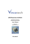
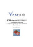
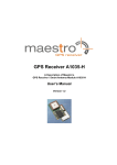
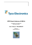
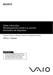
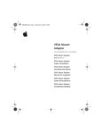
GPS Receiver A1035-E
A Description of Vincotech’s
GPS Smart Antenna Module A1035-E
User’s Manual
Version 1.3
Hardware Revision 01
Revision History
Rev.
1.0
1.1
1.2
1.3
Date
05-19-08
06-30-08
11-03-08
02-18-09
mm-dd-yy
V1.3 – Feb-09
Description
Initial Draft – preliminary information
Information added
New layout; moved to Vincotech
User’s Manual
Page 2 of 22
Disclaimer
THIS DOCUMENT CONTAINS PROPRIETARY INFORMATION OF VINCOTECH
GMBH. IT MAY NOT BE COPIED OR TRANSMITTED BY ANY MEANS, PASSED
TO OTHERS, OR STORED IN ANY RETRIEVAL SYSTEM OR MEDIA, WITHOUT
PRIOR CONSENT OF VINCOTECH OR ITS AUTHORIZED AGENTS.
THE INFORMATION IN THIS DOCUMENT IS, TO THE BEST OF OUR
KNOWLEDGE, ENTIRELY CORRECT. HOWEVER, VINCOTECH CAN NEITHER
ACCEPT LIABILITY FOR ANY INACCURACIES, OR THE CONSEQUENCES
THEREOF, NOR FOR ANY LIABILITY ARISING FROM THE USE OR
APPLICATION OF ANY CIRCUIT, PRODUCT, OR EXAMPLE SHOWN IN THE
DOCUMENT.
THE PRODUCT (HARD- AND SOFTWARE) DESCRIBED IN THIS DOCUMENTATION IS NOT AUTHORIZED FOR USE IN LIFE SUPPORT DEVICES OR
SYSTEMS WITHOUT THE EXPRESS WRITTEN APPROVAL OF VINCOTECH.
THIS DOCUMENT MAY PROVIDE LINKS TO OTHER WORLD WIDE WEB SITES
OR RESOURCES. BECAUSE VINCOTECH HAS NO CONTROL OVER SUCH
SITES AND RESOURCES, VINCOTECH SHALL NOT BE RESPONSIBLE FOR
THE AVAILABILITY OF SUCH EXTERNAL SITES OR RESOURCES, AND DOES
NOT ENDORSE AND IS NOT RESPONSIBLE OR LIABLE FOR ANY CONTENT,
ADVERTISING, PRODUCTS, OR OTHER MATERIALS ON OR AVAILABLE
FROM SUCH SITES OR RESOURCES. VINCOTECH SHALL NOT BE
RESPONSIBLE OR LIABLE, DIRECTLY OR INDIRECTLY, FOR ANY DAMAGE
OR LOSS CAUSED OR ALLEGED TO BE CAUSED BY OR IN CONNECTION
WITH USE OF OR RELIANCE ON ANY SUCH CONTENT, GOODS OR
SERVICES AVAILABLE ON OR THROUGH ANY SUCH SITE OR RESOURCE.
VINCOTECH RESERVES THE RIGHT TO CHANGE, MODIFY, OR IMPROVE
THIS DOCUMENT OR THE PRODUCT DESCRIBED HEREIN, AS SEEN FIT BY
VINCOTECH WITHOUT FURTHER NOTICE.
V1.3 – Feb-09
User’s Manual
Page 3 of 22
Table of Contents
1 Introduction ........................................................................................................ 6
1.1 Label ................................................................................................................. 6
1.2 Characteristics .................................................................................................. 7
1.3 Mechanical Characteristics ............................................................................... 7
1.4 Handling Precautions ........................................................................................ 7
2 Ordering Information ......................................................................................... 8
2.1 GPS Receiver A1035-E .................................................................................... 8
2.2 Packing of the A1035-E .................................................................................... 8
2.3 A1035-E Clips ................................................................................................... 9
2.4 Additional Equipment ........................................................................................ 9
3 Quick Start........................................................................................................ 10
3.1 Minimum Configuration ................................................................................... 10
3.2 Serial Port Settings ......................................................................................... 11
3.3 Improved TTFF ............................................................................................... 11
4 Mechanical Outline .......................................................................................... 12
4.1 Overview A1035-E .......................................................................................... 12
4.2 Connector A1035-E......................................................................................... 13
5 Pin-out Information .......................................................................................... 14
5.1 Layout A1035-E .............................................................................................. 14
5.2 Description A1035-E Signals .......................................................................... 15
5.3 General Comments ......................................................................................... 16
6 Electrical Characteristics ................................................................................ 17
6.1 Operating Conditions ...................................................................................... 17
6.2 Absolute Maximum Ratings ............................................................................ 17
7 Mounting........................................................................................................... 17
8 Quality and Reliability...................................................................................... 18
8.1 Environmental Conditions ............................................................................... 18
8.2 Product Qualification ....................................................................................... 18
8.3 Production Test ............................................................................................... 18
9 Applications and Hints .................................................................................... 19
9.1 1PPS pin (1 pulse per second pin).................................................................. 19
9.2 Enable Pin....................................................................................................... 19
9.3 Standby Pin..................................................................................................... 19
10 Demonstration Kit A1035-E ........................................................................... 20
11 Related Information ....................................................................................... 21
11.1 Contact.......................................................................................................... 21
11.2 Related Documents....................................................................................... 21
11.3 Related Tools ................................................................................................ 21
V1.3 – Feb-09
User’s Manual
Page 4 of 22
12 List of Tables .................................................................................................. 22
13 List of Figures ................................................................................................ 22
V1.3 – Feb-09
User’s Manual
Page 5 of 22
1 Introduction
Vincotech’s smart GPS antenna A1035-E is the combination of a highly integrated
GPS receiver module and a ceramic GPS patch antenna. The antenna is connected to the module via an LNA. The module is capable of receiving signals from
up to 12 GPS satellites and transferring them into position and timing information
that can be read over a serial port. Small size and high-end GPS functionality are
combined at low power consumption:
•
•
•
•
•
Operable at 1.8V / 73mW (typ.) @ trickle power mode
Small form factor of 21 x 21 mm (0.83” x 0.83”)
Standard power and I/O connector
Mountable without solder process
Field replaceable
The smart antenna module is available as an off-the-shelf component, 100% tested
and shipped in trays.
Note: The module can be offered for OEM applications with adaptation in form and
connection. Additionally, the antennas can be tuned to their final environment.
1.1 Label
The A1035-E’s labels hold the following information:
A1035-E200-01-1
YK 47/08
Vincotech
Product code (A1035-E) with software version (200) and
software revision (01) and hardware revision (1)
Factory (YK: Bicske) and date code (week/year: 47/08)
Figure 1: A1035-E labels
V1.3 – Feb-09
User’s Manual
Page 6 of 22
1.2 Characteristics
The antenna modules are characterized by the following parameters.
Channels
Correlators
Frequency
Tracking Sensitivity
Position Accuracy
Time To First Fix – TTFF
(theoretical minimum values;
values in real world may differ)
Stand alone
Obscuration recovery (1)
Hot start (2)
Warm (3)
Cold (4)
12, parallel tracking
> 32,000
L1 (= 1,575 MHz)
-157 dBm
< 5 m CEP (SA off)
0.1 s
<1s
< 35 s
< 37 s
Table 1: A1035-E characteristics
(1)
(2)
(3)
(4)
The calibrated clock of the receiver has not stopped, thus it knows precise time (to the µs level).
The receiver has estimates of time/date/position and valid almanac and ephemeris data.
The receiver has estimates of time/date/position and recent almanac.
The receiver has no estimate of time/date/position, and no recent almanac.
1.3 Mechanical Characteristics
Mechanical dimensions
Length
Width
Height
Weight
21.2 mm, 0.835”
21.2 mm, 0.835”
7.8 mm, 0.307”
5.6 g, 0.2 oz
Table 2: A1035-E dimensions and weight
1.4 Handling Precautions
The smart GPS antenna A1035-E is a module that is sensitive to electrostatic discharge (ESD). Please handle with appropriate care.
V1.3 – Feb-09
User’s Manual
Page 7 of 22
2 Ordering Information
2.1 GPS Receiver A1035-E
The order numbers are built as follows:
•
V23993A1035Exxx
“V23993” stands for Vincotech’s wireless and communication products, the “A1035E” for the A1035-E module. The “xxx” stands for the according firmware version. If
no firmware version is noted in an order, the latest version will be provided.
2.2 Packing of the A1035-E
The A1035-E comes in trays.
Figure 2: A1035-E tray specification (1)
One tray holds 96 A1035-E modules.
One box can hold 11 trays with a stacking height of about 12 mm. 11th tray is used
as cover, therefore 10 filled trays with a total of 960 modules in one complete box.
V1.3 – Feb-09
User’s Manual
Page 8 of 22
2.3 A1035-E Clips
In order to support easy mounting and dismounting of the A1035-E antenna modules, special clips have been developed. These clips can be ordered separately
(see “2.4 Additional Equipment”).
Figure 3: A1035-E clip
Details on the clip and a note how to use it can be found in the appropriate application notes / manuals.
2.4 Additional Equipment
V23993EVA1035E
V23993A1035ECLIP
Demonstration Kit (including one module V23993A1035E)
Mounting clip for A1035-E module
Table 3: Additional equipment
A detailed description of the EVA1035-E Evaluation Kit can be found in the appropriate manual.
V1.3 – Feb-09
User’s Manual
Page 9 of 22
3 Quick Start
In order to allow an easy and quick start with the modules A1035-E, this chapter
provides a short overview on the most important steps to receive NMEA messages
with position information on a serial port. For details please refer to the according
chapters.
3.1 Minimum Configuration
The following picture shows a recommended minimum configuration for the connection of a micro-controller within a 3.3 V environment
Figure 4: Recommended minimum configuration A1035-E
V1.3 – Feb-09
User’s Manual
Page 10 of 22
3.2 Serial Port Settings
The default configuration within the standard GPS firmware is:
•
Serial 0 (NMEA) 19,200 baud, 8 data bits, no parity, 1 stop bit, no flow control
3.3 Improved TTFF
In order to improve the TTFF (Time To First Fix), it is recommend to keep the Vcc
all the time and use Enable PIN (see chapter “9.2 Enable Pin”) or software standby
function.
V1.3 – Feb-09
User’s Manual
Page 11 of 22
4 Mechanical Outline
4.1 Overview A1035-E
All dimensions in [mm]
Figure 5: Mechanical outline overview A1035-E (bottom)
All dimensions in [mm]
Figure 6: Mechanical outline overview A1035-E (top)
V1.3 – Feb-09
User’s Manual
Page 12 of 22
All dimensions in [mm]
Figure 7: Mechanical outline overview A1035-E (side A)
All dimensions in [mm]
Figure 8: Mechanical outline overview A1035-E (side B)
4.2 Connector A1035-E
The power and I/O connector used on the A1035-E is a 1.27mm (0.05”) low profile,
double row socket with a height of 2.21mm (.087”) and a total of 22 contacts. Potential counterparts on the motherboard are e.g. Samtec 1.27mm (0.05”) micro
strips of the FTS series (e.g. FTS-111-02-L-DV-P-TR).
V1.3 – Feb-09
User’s Manual
Page 13 of 22
5 Pin-out Information
5.1 Layout A1035-E
Pin 1
Vcc
Vcc
Vcc
Vcc
Vcc
Vcc
GND
GND
GND
GND
GND
Pin 2
Pin 2
Vcc
Res
Stndby
Enable
Res
Res
Res
Rx
Tx
Res
Active
Vcc
Res
Stndby
Enable
Res
Res
Res
Rx
Tx
Res
Active
Pin 1
Vcc
Vcc
Vcc
Vcc
Vcc
Vcc
GND
GND
GND
GND
GND
Figure 9: Pin out information A1035-E (bottom and top view)
Bottom view is showing the side of the module that will face the carrier board.
V1.3 – Feb-09
User’s Manual
Page 14 of 22
5.2 Description A1035-E Signals
This table describes the functionality of the pins and their associated symbols.
Please note: all Vcc Pin must be connected to power supply!
Pin Symbol
1 Vcc
Function
Input
Description
1.8V VDC (power supply)
3
Vcc
Input
1.8V VDC (power supply)
5
Vcc
Input
1.8V VDC (power supply)
7
Vcc
Input
1.8V VDC (power supply)
9
Vcc
Input
1.8V VDC (power supply)
11
Vcc
Input
1.8V VDC (power supply)
13
GND
GND
Ground
15
GND
GND
Ground
17
GND
GND
Ground
19
GND
GND
Ground
21
GND
GND
Ground
Table 4: Pin description A1035-E (part 1)
Pin Symbol
2 Vcc
Function
Input
Description
1.8V VDC (power supply)
4
Res.
Reserved – leave open
6
Stndby
Input
Standby
8
Enable
Input
Enable
10
Res.
Reserved – leave open
12
Res.
Reserved – leave open
14
Res.
Reserved – leave open
16
RX
Input
Serial 19,200 baud input
18
TX
Output
Serial 19,200 baud output
20
1PPS
Output
1PPS – (pulse per second) Signal
22
Active
Output
High when module is working
Table 5: Pin description A1035-E (part 2)
V1.3 – Feb-09
User’s Manual
Page 15 of 22
5.3 General Comments
The following comments should be considered for a design with and use of the
module:
•
Standard configuration of serial port:
Serial 0 (NMEA) 19,200 baud, 8 data bits, no parity, 1 stop bit, no flow control
V1.3 – Feb-09
User’s Manual
Page 16 of 22
6 Electrical Characteristics
6.1 Operating Conditions
Pin
1,
2,
3
Description
Vcc
Peak Acquisition Current (1)
Average Acquisition Current (2)
Tracking Current (3)
Standby Current (4)
Min
1.8V
Typical
1.85V
120mA
60mA
40mA
20 µA
Max
1.9V
130mA
Table 6: Operating Conditions
(1) Peak acquisition current is characterized by millisecond bursts above average acquisition current
(2) Average current is typically only the first two seconds of TTFF
(3) Tracking current typically includes tracking and the post acquisition portion of TTFF
(4) During standby state: RTC block and core powered on and clock off.
6.2 Absolute Maximum Ratings
Symbol
VCC
Vin
Iout
Itdv
Parameter
Power Supply GSCi500x
Voltage to any input pin
Input current on any pin
Absolute sum of all input currents during overload condition
Min Max Unit
-0.3 1.95
V
-0.3 +2.0
V
-10 +10 mA
200 mA
Table 7: Absolute maximum ratings
Stresses beyond those listed under “Absolute Maximum Ratings” may cause permanent damage to the device. This is a stress rating only. Functional operation of
the device at these or any other conditions beyond those indicated in the operational sections of this specification is not implied. Exposure to absolute maximum
rating conditions for extended periods may affect device reliability.
7 Mounting
The A1035-E offers a power and I/O connector with a 1.27mm (0.05”) low profile,
double row socket with a total of 22 contacts. Potential counterparts on the motherboard are Samtec 1.27mm (0.05”) micro strips of the FTS series. For fixing the
A1035-E on a motherboard separately provided clips are recommended.
For details on the mounting clip and further mounting instructions please refer to the
according documents.
V1.3 – Feb-09
User’s Manual
Page 17 of 22
8 Quality and Reliability
8.1 Environmental Conditions
Operating temperature
Operating humidity
- 30 … + 85°C
Max. 85% r. H., non-condensing, at 85°C
Table 8: Environmental conditions
8.2 Product Qualification
Basic qualification tests:
•
•
•
•
•
•
Temperature Cycling –30°C … +85°C
Temperature Humidity Bias 85°C / 85% RH
High / Low Temperature Operating –30° / +85°C
High Temperature Operating Life +85°C
Vibration Variable Frequency
Mechanical Shock
Please contact Vincotech for detailed information.
8.3 Production Test
Each module is electrically tested prior to packing and shipping to ensure state of
the art GPS receiver performance and accuracy.
V1.3 – Feb-09
User’s Manual
Page 18 of 22
9 Applications and Hints
9.1 1PPS pin (1 pulse per second pin)
The 1PPS pin is an output pin.
In addition to precise positioning, GPS also allows for accurate timing due to the
synchronized atomic clocks in the GPS satellites. While the current date and time is
transmitted in NMEA sentences, an exact and accurate timing signal is provided via
the 1PPS pin of the A1035-E modules.
Note: The 1PPS clock accuracy directly depends on the position accuracy! The
GPS signals travel at the speed of light, therefore a position inaccuracy directly
translates into 1PPS inaccuracies.
10 m position deviation ≈ 33 ns 1PPS deviation (typically)
100 m position deviation ≈ 333 ns 1PPS deviation (typically)
The 1PPS signal is provided on a “as is” basis with no accuracy specification.
The given values are based on a 10 satellite, static GPS simulator scenario.
The 1PPS pin is an output pin.
9.2 Enable Pin
The Enable pin is an input PIN and high active.
The module will immediately switch to standby mode by pulling the Enable pin to
“low”. The RTC keeps running and the internal SRAM will be back upped. This
keeps the Ephemeris and Almanac stored. Pulling the Enable pin back to “high”
within 2 hours will end in hot start situation.
9.3 Standby Pin
The Standby pin is an input pin and high active.
Pulling Standby pin to high will activate “Keep Ephemeris Alive” mode with factory
preset variables (reactivating the acquisition / tracking mode after 60 minutes power
save mode). Please see Firmware manual A1082-A.
V1.3 – Feb-09
User’s Manual
Page 19 of 22
10 Demonstration Kit A1035-E
For demonstration and easy evaluation of GPS performance Vincotech offers an
Evaluation Kit (including one GPS A1035-E module) It contains a USB interface
with according drivers to connect easily to a PC. The USB interface is an extension
of the serial port 0, therefore sending NMEA sentences and accepting commands.
At the same time it provides power to the module.
For the development of new software and applications the Evaluation Kit also provides NMEA messages on C-MOS level via a terminal plug.
Figure 10: Evaluation kit EVA1035-E
For further information please contact Vincotech.
V1.3 – Feb-09
User’s Manual
Page 20 of 22
11 Related Information
11.1 Contact
This manual was created with due diligence. We hope that it will be helpful to the
user to get the most out of the GPS module.
Any inputs regarding possible errors or mistakable verbalizations, and comments or
proposals for further improvements to this document, made to Vincotech, Germany,
are highly appreciated.
Vincotech GmbH
Biberger Str. 93
82008 Unterhaching (Munich)
Germany
Tel.: +49 89 8780 67 0
Fax: +49 89 8780 67 351
[email protected]
www.vincotech.com/gps
11.2 Related Documents
•
•
•
•
•
•
GPS Evaluation Kit EVA1035-H (Vincotech)
GPS Firmware A1082-A (Vincotech)
GPS AppNote A1082 & A1035-E Power Supply (Vincotech)
GPS A1035-E Clip Specification (Vincotech)
GPS A1035-E Mounting Instruction(Vincotech)
Instant GPS IC Interface Control Drawing manual (SiRF)
11.3 Related Tools
•
GPS Cockpit (Vincotech)
V1.3 – Feb-09
User’s Manual
Page 21 of 22
12 List of Tables
Table 1: A1035-E characteristics ............................................................................. 7
Table 2: A1035-E dimensions and weight................................................................ 7
Table 3: Additional equipment.................................................................................. 9
Table 4: Pin description A1035-E (part 1) .............................................................. 15
Table 5: Pin description A1035-E (part 2) .............................................................. 15
Table 6: Operating Conditions ............................................................................... 17
Table 7: Absolute maximum ratings ....................................................................... 17
Table 8: Environmental conditions ......................................................................... 18
13 List of Figures
Figure 1: A1035-E labels.......................................................................................... 6
Figure 2: A1035-E tray specification (1) ................................................................... 8
Figure 3: A1035-E clip.............................................................................................. 9
Figure 4: Recommended minimum configuration A1035-E.................................... 10
Figure 5: Mechanical outline overview A1035-E (bottom) ...................................... 12
Figure 6: Mechanical outline overview A1035-E (top) ............................................ 12
Figure 7: Mechanical outline overview A1035-E (side A) ....................................... 13
Figure 8: Mechanical outline overview A1035-E (side B) ....................................... 13
Figure 9: Pin out information A1035-E (bottom and top view)................................ 14
Figure 10: Evaluation kit EVA1035-E ..................................................................... 20
V1.3 – Feb-09
User’s Manual
Page 22 of 22