1
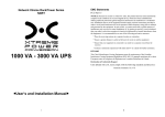
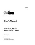
User Manual Installation Operation Maintenance 200 Watt ~ 490 Watt Auxiliary Lighting and Power Equipment 6005-100 Revision A *Due to continuous product improvement this document is subject to Change without prior notice. NOTICE: This document contains PROPRIETARY INFORMATION. Reproduction or distribution FORBIDDEN! This document contains proprietary and confidential information of Online Power, Inc. In consideration of the receipt of this document, the recipient agrees not to copy any of its contents, nor to disclose them to or allow them to be used by any person not currently an Online Power employee or an employee of the recipient having a need to know, without the express written consent of Online Power, and further agrees to surrender this document to Online Power when the reason for its receipt has terminated. Due to continuous product improvement this document is subject to change without prior notice. © 2009 Online Power, Inc. –All rights reserved I 6005-100 Rev A Congratulations on selecting one of the fine products from Online Power, the leader in power protection technology. Our wide product offering includes UPS (Uninterruptible Power Systems), power conditioners, automatic voltage regulators and specialty transformers (e.g., computer-grade, medical-grade). Since our founding in 1972, Online Power has shipped many of these fine products to discerning customers around the world for use on sensitive equipment and in critical applications. One of our goals is to make our manuals both comprehensive and easy to use. The new format of our user manual is the result of ideas and inputs from customers like you who have taken an active interest in our continued success. We invite and appreciate your feedback on our products and documentation via e-mail, fax, mail, or telephone. HEADQUARTERS Online Power 5701 Smith Street Commerce, CA 90040 SALES Phone: (800) 227-8899 FAX No: (323) 721-5017 E-mail: [email protected] Office Hours are 7:00 AM to 5:00 PM PST SERVICE If you require assistance, please call our 24-hour toll free hot line 800-PWR-SRVC (800-797-7782) or email to [email protected]. Please have the following information from your unit’ s nameplate available to speed assistance: Serial Number: KVA/Power Rating: Input Voltage: Output Voltage: Manufacturer Date: II 6005-100 Rev A IMPORTANT SAFETY SAVE THESE INSTRUCTION III 6005-100 Rev A IV 6005-100 Rev A V 6005-100 Rev A VI 6005-100 Rev A TABLE OF CONTENTS SECTION PAGE SECTION 1 –INTRODUCTION 1 SECTION 2 –SYSTEM DESCRIPTION 1 2.1 2.2 General Description System Configuration 1 3 SECTION 3 –SAFETY INFORNATION 4 SECTION 4 –STORAGE 5 SECTION 5 –INSTALLATION 5 5.1 5.2 5.3 Environment Installation Layout Connection to mains and loads 5 6 7 SECTION 6 –OPERATION 6.1 6.2 6.3 6.4 9 Staring and shutting down the UPS Button Operation Control Panel Functions Interpreting UPS messages 9 9 10 14 SECTION 7 –TROUBLE SHOOTING 15 SECTION 8 –MAINTENANCE 16 8.1 Replacing Batteries 16 SECTION 9 –COMMUNICATONS 17 SECTION 10 –OPTIONS 19 SECTION 11 –TECHNICAL SPECIFICATIONS 20 VII 6005-100 Rev A INSTRUCTIONS Special Symbols The following symbols used on the UPS warn you of precautions: RISK OF ELECTRIC SHOCK –Please observe the warning that a risk of electric shock is present. CAUTION: REFER TO OPERATOR’ S MANUAL - Refer to the operator’ s manual for additional information, such as important operating and maintenance instructions. SAFE GROUNDING TERMINAL - Indicates primary safe ground LOAD ON/OFF - Pressing this button turns on/off the output receptacles and the Indicator light. RJ-45 RECEPTACLE - The receptacle provides network interface connections and telephone or telecommunications equipment should not be plugged into it. Please do not discard the UPS or UPS batteries as the UPS may have valve regulated, lead–acid batteries. Please recycle batteries. VIII 6005-100 Rev A 1. Introduction The information provided in this manual covers single phase 200-490watt, uninterruptible power systems, their basic functions, operating procedures, and emergency situations, also including information on how to ship, store, handle and install the equipment. Only detailed requirements of the UPS units are described herein, and installation must be carried out in accordance with this manual. Electrical installations must also carefully follow local legislation and regulations. Only qualified personnel should conduct these installations as failure to acknowledge electrical hazards could prove to be fatal. Important Notice: To be sure that the UPS will be open correctly, the following items should be noticed: a. Read instructions carefully before operating the UPS. b. UPS power connect instruction should be followed. c. Please don’ t open the case to prevent danger. d. If the UPS will be stored for long period, the battery must be charged once every 90 days. e. Retain the load within the rating of UPS to prevent faults. f. Handle unusual events according to the trouble-shooting guide. g. Keep the UPS clean and dry. 2. System description Several different kinds of sensitive electrical equipment stay protected by a UPS (Uninterruptible Power System) including computers, workstations, process control systems, telecommunications systems, sales terminals, other critical instrumentation, etc. The purpose of the UPS is to protect these systems from poor quality utility power, complete loss of power, or other associated problems. Electrical interference abounds in many forms causing problems in AC power, from lightning, power company accidents and radio transmissions to motors, air conditioners, and vending machines, among others. So protection of sensitive electrical equipment is vital to protect against power outages, low or high voltage, slow voltage fluctuations, frequency variations, differential and common-mode noises, transients, etc. In order to prevent power line problems reaching critical systems causing damage to software, hardware and causing equipment to malfunction, the UPS helps by maintaining constant voltage, isolating critical load output if needed, and cleaning the utility AC power. 2.1 General description As a double conversion on-line UPS, it is able to supply uninterrupted, clean single-phase power to your critical systems while keeping batteries charged continuously, regardless of whether utility power fails or not. In event that a power failure lasts longer than a UPS backup time, it will shut down avoiding battery discharge, and as soon as voltage comes back, the UPS will automatically charge up and start recharging the batteries. As shown in fig.1 block diagram: An input filter reduces transients on the mains For maintaining full battery charge, AC-power is rectified and regulated in the rectifier feeding power to the inverter and battery converter. DC power is converted to AC in the inverter passing it on to the load. Power is maintained from the battery during a power failure. The converter increases voltage appropriately for the inverter. 1 6005-100 Rev A Fig.1. Block diagram Efficiency Optimizer function The Efficiency Optimizer function is a new feature for the UPS adding cost effectiveness, minimizing power loss and reducing power consumption. Alternating between bypass and on-line modes is achieved automatically and in accordance with the conditions of the utility power. On-line mode may be used during times of intermittent power supply, and bypass mode when power flows smoothly in order to obtain greatest efficiency. Irregularities can be detected in less than a second, and on-line mode reactivated immediately. Switching back to online mode occurs when input voltage is outside ±10% or nominal (±15% selectable), when input frequency is outside of ±3Hz or when no input line is available. Although high efficiency is standard, the default operation is in on-line mode. Bypass can be activated in the LCD panel; though on-line can be run permanently if preferred. Free Run Mode The UPS operates in free run mode when input frequency is outside of the selected input frequency range. Free run mode is when output frequency does not match input frequency. When starting the UPS, the frequency regulation detected is 50 or 60 Hz ±0.25Hz. Please refer to chapter 7.2 if you want bypass available while running in free run mode. Diagnostic tests When you start the UPS, a diagnostic test is automatically executed that checks electronics, battery, and reports any problems on the LCD display. An advanced battery management system always monitors the conditions of the batteries sends any forewarnings if replacement is needed. Otherwise every 30 days of normal mode operation, a battery discharge test is performed and any problems reported on the LCD display. Except during the first 24 hours after startup while the UPS is in charging mode (please see chapter 7.2), diagnostic tests can be performed manually from the front panel at any time. 2 6005-100 Rev A 2.2 System Configuration The UPS device and the internal backup battery make up the system. Depending on the site and load requirements of the installation, certain additional options are available as a tailored solution. Planning a UPS system, the following should be taken into consideration: The total demand of the protected system shall dictate the output power rating (Watts). Allow a margin for future expansion or calculation inaccuracies from measuring power requirements. Backup time at the indicated power rating is 90 minutes. The following UPS models are available Wall/Floor Mountable Lighting Inverter 90 minute battery back up (Batt. 24 VDC) Total/ WATT 200W 300W 490W Model Numbers Input/Output Voltages BTU/ Hr WM.20A01OP 120V/120V 216 WM.20R01OP 277V/120V 233 WM.20R25OP 277V/277V 233 WM.20A25OP WM.30A01OP 120V/277V 120V/120V 233 WM.30R01OP 277V/120V 353 WM.30R25OP 277V/277V 353 WM.30A25OP 120V/277V 353 WM.49A01OP 120V/120V 499 WM.49R01OP 277V/120V 543 WM.49R25OP 277V/277V 543 WM.49A25OP 120V/277V 543 Cabinet Dimension (W” xH” xD” ) 24 X 17 X 9.5 305 “ “ (NOTE) ** BTU/HR ARE APROX. NUMBER WITH TOLERANCE ± 15% FOR ALL MODELS 3 6005-100 Rev A 3. Safety Information Information presented here is vital to all personnel and please also read the UPS safety manual. Storage and Transportation Please handle with extreme caution since a high amount of energy is contained with the batteries. Always keep the unit in position as marked on the packaging and never drop the unit. Installation If flammable substances such as gases or fumes are present or if the room is airtight, a safety hazard situation exists, in which no electrical equipment should be operated. The instructions in this manual explain how to install the UPS safely. Not acknowledging such electrical hazards may be fatal, so keep this manual for all future reference. WARNING! It is strongly advisable not to open the UPS cabinet as the components have very high voltage and touching them may be fatal. Only a technician from the manufacturer or an authorized agent may service the unit. This UPS unit’ s output receptacles carry live voltage even when not connected to a power supply as it has its own energy source. User’ s operations The only operations that users are permitted to do are: Turning the UPS unit on and off Operating the users interface Connecting data interface cables Changing the batteries All such operations are to be performed exactly as instructed in this manual. The greatest care possible must be taken for any of these operations and any change thereof may prove very hazardous to the operator. 4 6005-100 Rev A 4. Storage Please adhere to the following instructions if the UPS is not installed immediately: Store the equipment as is in its original packing and shipping carton Do not store in temperatures outside the range of +15°C to +25°C. Ensure that the equipment is fully protected from wet or damp areas and from moist air. In order to maintain the vitality of the batteries, ensure that the UPS is recharged every 6 months for at least 8 hours. 5. Installation 5.1 Environment Ensure that all environmental concerns and requirements are met according to these technical specifications, otherwise the safety of installation personnel cannot be guaranteed and the unit may malfunction. Ensure that you remember the following when locating the UPS system and battery options: Avoid extremes of temperature and humidity. Maximal battery life can be attained with a recommended temperature range of 15 °C to 25 °C. Provide protection for the equipment from moisture. Ensure that the front of the UPS remains clear for user operation. Space and ventilation requirements must be met (see below). 5 6005-100 Rev A 5.2 Installation Layout: Customer to supply hardware and to ensure the wall structure and material is proper for the load handling of the unit 6 6005-100 Rev A 5.3 Connection to mains and loads Battery connection 7 6005-100 Rev A The installation is now complete 8 6005-100 Rev A 6. Operation Necessary information for operation of the unit is covered in this chapter. Normally the UPS runs automatically, but on those few occasions such as just after installation, all the starting and shutting down procedures are described herein. 6.1 Starting and shutting down the UPS Starting the UPS Ensure that installation was correct and successful and that the input power cable is connected to a well-grounded outlet. The UPS can be started by pushing the button on the front panel. The UPS should now start its inspection of: internal functions, main synchronization and inverter startup. Then power should start to be supplied via the outlets. During this inspection, the LCD will display “ Ready on” . The LED shall light up when output power has commenced and the LCD will display “ Line mode” . Switch on the loads. Shutting down the UPS Shut down and turn off the loads. Push the button on the front panel for five seconds. The alarm will sound and the UPS will shut down. The LCD will display UPS OFF for a few seconds. In emergency situations, the EPO located on the back of the unit should be used. 6.2 Button Operation Please note the three operating buttons on the front panel: 1. “ ”is an ON/ OFF button: (a). Push the “ ”button (at least 3 seconds) to turn on the UPS. (b). When UPS is working, push the “ ”button (at least 3 seconds) to turn off the UPS. 2. “ ”is an Enter button. Use this button to check content of UPS and the method is listed Below: (a). Push the “ ”button (at least 2 seconds) to check content of UPS. Each content can be displayed by pressing at once, and it has fifteen kinds of function to be checked. (b) If no pressing within 10 seconds, it will return to original status. 3. “ ”is a Function button. Each function can be enabled by pressing this button. (a). Push the “ ”button (at least 2 seconds) to choose which function that you want. Each content can be displayed by pressing at once, and it has fourteen kinds of function to be checked. (b). After choosing the function, push the “ ”button to enter the function that you want. (c). Push the “ ”button to choose other function again. (d). Push the “ ”button to enable your function. (e). Push the “ ”button to confirm and enable your function. (f). If no pressing within 10 seconds, it will return to original status. 9 6005-100 Rev A 6.3 Control Panel functions Operation of the UPS is indicated on the monitor panel with five LED indicators and an LCD screen. This display is also capable of alerting the user with audible alarms. ON This green LED is lit when UPS has been turned on. OUTPUT AVAIL When the UPS is in normal or static bypass modes, there is voltage at the output terminals and this LED will light up in green. BATT MODE While operating in battery mode. BYPASS MODE While operating in bypass mode, this LED will light up in yellow. FAULT If any internal error occurs in the UPS, this LED will light up in red and give off an audible alarm. Press any of the buttons on the front panel to turn off the alarm. 10 6005-100 Rev A Status of the UPS, measurements and alarms are all indicated on the LCD screen. Figure 6. Control panel Normal display The UPS status is shown in normal display mode. From here you have a choice to go to UPS meters display and the Setting display by pushing the button. UPS meters display Various measurements are available through the UPS meters display; pressing the button will scroll through the following meters: LCD message Description O/P VOLT= xxx, xV Shows Output AC voltage O/P FREQ= xx, x Hz Shows Output Frequency I/P VOL T= xxx, xV I/P FREQ= xx, x Hz Shows Input AC voltage Shows Input Frequency BAT VOLT= xx,xV Shows Battery Voltage O/P LOAD%= xx% Shows Load % of max load O/P W= xW O/P VA= xVA Shows Output Watts Shows Output VA O/P CURR= xA Shows Output Current BACKUP TIME= xx min Shows Estimated Backup time in minutes BAT CHARG= xx% Shows approximate percentage of Battery capacity TEMPERATURE= xxC Shows approximate ambient temperature BAT PACK NUM= x RATING = xxxxVA Shows External Battery Pack Number Shows UPS Rating CPU VERSION xx.x Shows CPU Version 11 6005-100 Rev A UPS configurations 1. Various settings that have been chosen are shown in the UPS setting display. 2. To enter configuration mode, press the be shown on the LCD display. button for one second. The first configuration parameter will 3. Press the button to scroll through the parameters. 4. Press the button to select the parameter. 5. Press the button to scroll through the options for the selected parameter; Press the button to select the option. You may be prompted to save the selection, if so press the button to either confirm or save your selection. Other options are saved and started automatically. See the table below for further details. 6. If no buttons are pressed (or user inactivity) for ten seconds, the UPS shall exit the configuration mode and return to normal mode displaying Line mode. Caution! The factory default settings do not necessarily have to be changed, although you are free to tailor the UPS to your specific needs. 12 6005-100 Rev A Settings Output Volt.Setting LCD display O/P V Setting Explanation Select Nominal Voltage Selection Factory default 208/220/230/240 V 230V 100/110/115/120/127 V 120V I/P F Setting Select input frequency range when UPS goes into free run mode Input/Bypass Voltage I/P Bypass Set Select Input Voltage range when bypass is available ±2% ±5% ±7% ±10% +10/-15% +15/-20% Free Run Mode Free Run Set Select if UPS can run in Free run mode (unsynchronized) ON/OFF ON Bypass disable If Enable is chosen, the UPS can go to bypass when unsynchronized. Disable/Enable Disable HE Mode Set Select if UPS runs in high efficiency mode ON/OFF OFF Force Manual Bypass Manual bypass Permanently force UPS to bypass. For service only.** ON/OFF OFF Management of Load groups Outlet Setting You can put the two load groups on and off form front panel 1 ON & 2 ON 1 OFF & 2 ON 1OFF & 2 OFF 1 ON & 2 OFF Both load segments ON Do Battery Test Battery Test Detect battery is normal or not. Silence Function Silence Set Enable or disable silence function ON/OFF OFF Bat Cabinet Set This setting is needed For UPS to predict Backup time 0 (only internal batteries) 1(one external cabinet) 2 (two external cabinets) 0 Site wiring alarm Sit Fault Set You can enable or disable the site wiring alarm Enable /Disable Disable Select Language Language Select load language English, German, French, Spanish, Italian. English Set Generator Mode Generator Set unit in generator mode. *** ON/OFF OFF Enable/Disable Enable Input/Frequency Bypass Enable/Disable at Free run mode He mode Setting Number of External battery Packs communication Set RS232 communication RS232 Control Set RS232 enable or disable 13 ±5% +10/-15% 6005-100 Rev A Manual test of the UPS Manual UPS or Manual Battery tests can be conducted from the UPS configuration as well and are functional even when the UPS is not charging the battery. Manual Battery test: Scroll the parameters until Manual Bat test displays on the LCD. Press the button twice. **) Note: In order for the UPS and power management software to operate normally, Manual Bypass should always be set to OFF as the load will not be protected by the unit when Manual Bypass is ON. This is aimed for operating an external maintenance bypass switch. ***) Note: You should turn UPS off and keep the AC power before you use “ Generator”function. (even you want to select “ \Generator\OFF”to back to normal mode). 6.4 Interpreting UPS messages Troubleshooting procedures described here give simple instructions in determining UPS malfunctions. Start the troubleshooting procedure if you witness any alarm indication on the control panel. Alarm indicators The UPS gives the following audible alarms: If UPS is on battery and the ON BATTERY LED is on, UPS will beep every 5 seconds. If the battery capacity is low and the ON BATTERY LED is flashing, the UPS will beep twice every 5 seconds. If UPS is on bypass and the BYPASSED LED is on, UPS will no beep. If UPS has an internal fault and the ALARM LED is on, the UPS will give a constant audible alarm displaying the cause on the LCD display. Silencing an alarm By pressing any of the three buttons on the front panel, the alarm can be turned off, except when the battery is low, which will cause the alarm to resound. On the LCD display, you can also choose silent alarm mode which will not warn you of any malfunction audibly. 14 6005-100 Rev A 7. Trouble Shooting Displayed on LCD Audible Alarm Output Overload The UPS is overloaded (in Line Mode). Your needs more Two Beeps per second equipment power than the UPS can provide. The UPS operates in bypass. Alarm Description What You Should Do Shut off the least important equipment connected to the UPS. If this solves the overload problem, the UPS will switch from bypass back to normal operation. No action needed. The UPS will return to normal operation when it successfully completes the battery test. Turn off protected loads. Turn off UPS and call your local dealer Battery Test No Beeps The UPS is doing a battery test. Over-Charge Constant beep Batteries are overcharged. Low Battery 2 beeps every 5seconds The unit is operating on The unit will restart Battery Power and will Automatically when acceptable shut down soon due to power returns. very low battery voltage On-Battery unit is operating on Save your data and perform a Once every 5 seconds The Battery Power. controlled shutdown. Charger Failure Constant beep Charger has failed. Phone the local dealer Over-Temperature Constant beep High ambient Temperature. Make sure the unit’ s fans and vent holes are not blocked, and make sure the ambient surrounding temperature is not above 40 degree C. If these conditions did not solve the problem, call your service representative. Output Short High output Voltage Low Output Voltage Constant beep Output short circuit Call the Local dealer Constant beep High output voltage Call the Local dealer Constant beep Low output voltage Call the Local dealer 2 Beeps per second High internal DC bus Voltage. Turn off protected loads. Turn off UPS and call your local dealer UPS mains connector polarity Wrong. Rotate the connector (Schuko). UPS installed to mains supply without ground. See page 15 on how to disable the Site wiring alarm Bus Fault Site wiring Fault 1 Beep per second Voltage detected Between Neutral and Ground Line abnormal 1 Beep per second Wrong AC Line backed up during auto restart 15 6005-100 Rev A 8. Maintenance With a minimal amount of maintenance, you can expect the UPS to have a long life free of trouble. The most critical issues for the reliability of the UPS are environmental issues. Ensure that the temperature and humidity are always according to specifications and keep the area around the unit clean and dust free. At a temperature of 25°C, the typical battery lifetime is 4 years. Also check at regular intervals of 6 to 12 months whether the back-up time of the battery is adequate. 8.1 Replacing batteries The batteries may be replaced without having to turn the UPS off or disconnecting the load due to the hot-swappable battery feature. WARNING! Batteries may cause electrical shock or burn from high short circuit currents. Please observe the following precautions: 1. Remove jewelry and metal objects such as watches and rings. 2. Use tools that have insulated handles. 3. Keep tools and other metal objects from contacting and away from the batteries. ELECTRIC ENERGY HAZARD. Do not attempt to rewire, alter, or change any battery wiring or connectors. Attempting to make such alterations can cause injury. Replace the batteries with the same number and type as originally installed batteries. DO NOT DISCONNECT the batteries while UPS is in Battery mode. 16 6005-100 Rev A 9. Communication Communication ports are located on the front for easy access as shown below One RS232 serial data interface, one USB data interface In addition there is an optional interface slot (SNMP) Option that allows you to install different communications cards. It can be used parallel with either the RS232 or USB ports. Currently there are two cards available for the optional interface slot. An SNMP/WEB card allows management and monitoring over a network or internet, and the AS/400 card allows voltage free relay contacts. Your local dealer will have more information about these option cards. Note the RS232 port cannot be used when the USB interface is in use. 17 6005-100 Rev A Connecting the UPS to a Computer The communication device for the UPS and PC comes as a complete package with power management software. Only the communication cable provided with UPS may be used to connect to your computer, which is accomplished through the UPS RS232 port. Also ensure that the operating system on your computer is supported. Instructions provided in the power management software will help with this installation. Other advanced power protection solutions such as SNMP are provided by your dealer. RS-232 Standard Interface port The RS-232 interface uses a 9-pin female D-sub connector. This information consists of data about utility, load and the UPS. The interface port pins and their functions are identified in the following table. Max rated Pin # Signal nameCaution! Direction (re values UPS)12VdcFunctions 2 3 TxD RxD 5 Common Output Input TxD Output RxD / Inverter Off Input Common 6 Output Ac Fail Output 8 9 Output Output Low Battery Output 12 VDC Power USB port (option) Connecting the UPS to your computer is accomplished through the USB port on the back of your computer. USB compliant hardware and operating system will be necessary including installation of a UPS driver. The serial port cannot be used when using the USB port. The USB cable is standard and can be bought separately. 18 6005-100 Rev A 10. Options 10.1 Auxiliray TVSS 10.2 Auxiliary Output Circuit Breaker 10 amp (max. 3) 10.3 SNMP 10.4 Communication interface, RS232 10.5 Floor mount brackets 10.6 Remote Status 19 6005-100 Rev A 11. Technical Specification Specifications for 120V/277V Capacity (W) Input Output 200W 300W Voltage Single Phase 120Vac or 277V Voltage Range 120Vac ±10% or 277V Frequency 50Hz or 60Hz +/- 4Hz Power Factor > 95% Voltage (on battery) Single Phase 120Vac or 277V Voltage Range 120Vac ±2% or 277V Frequency (on battery) 50 / 60 Hz +/-0.5% Transfer Time 0 ms Overload Recovery Auto transfer to UPS 490W High Efficiency mode (AC to AC) > 95 % Protection and Filtering UPS Design Technology On-Line / Fully digitized microprocessor controlled Surge Protection 120V (IEEE C62.41) / 230V (IEEEC61000-4-5 level 3) Overload Protection 125% for 1 minutes and 150% for 10 seconds Short Circuit Protection Circuit breaker Visual Display UPS on(green), line-mode(green), (LED model) battery mode(yellow), bypass(yellow), fault(red) Visual Display Input / output voltage, input / output frequency, System/Display/ Warning (LCD model) on-line mode, back up mode, battery capacity, load level Audible Alarm Beep every 5 sec UPS Fault Continuous beeping sound and LCD display Communication RS-232 Serial Port and USB Battery 90 min. 2X35 A/H Dimensions Inches (width x Height x depth) 2X50 A/H 2X50 A/H 24 x 17 x 9.5 Note: Due to continuous improvement specifications are subject to change without prior notice 20 6005-100 Rev A