1
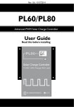
plasmatronics
SPS12D100 CHARGE REGULATOR
SOLAR POWER SUPPLY
CONTROLLER
MODEL SPS12D100B
100A CHARGE 50A LOAD
POSITIVE GROUND
Plasmatronics Pty Ltd
75 Newman Street
Thornbury VIC 3071 Australia
Ph: +61 3 9486 9902
Fax: +61 3 9480 3022
[email protected]
Plasmatronics
www.plasmatronics.com.au
P12D100B-V1
Page 1 of 17
plasmatronics
SPS12D100 CHARGE REGULATOR
TABLE OF CONTENTS
1. DESCRIPTION ............................................................................................................ 3
2. SPS12D100 - SPECIFICATIONS ...................................................................................... 4
3. OPERATION . ............................................................................................................. 5
3.1. CHARGE REGULATOR.................................................................................................. 6
3.2. CONTROL PANEL ...................................................................................................... 6
3.3. DISPLAY................................................................................................................. 7
3.4. LIGHTNING PROTECTION ............................................................................................. 9
3.5. MANUAL RESET ........................................................................................................ 9
3.6. CLEARING DATA MEMORY ........................................................................................... 9
3.7. ALARMS ................................................................................................................. 9
3.8. SERIAL PORTS ........................................................................................................ 10
4. INSTALLATION ........................................................................................................ 11
4.1. MOUNTING ........................................................................................................... 11
4.2. TEMPERATURE SENSOR ............................................................................................. 11
4.3. START UP ............................................................................................................. 12
5. BASIC FIELD SERVICE .............................................................................................. 12
5.1. SWITCH BOARD TEST PROCEDURE ................................................................................ 12
6. DIAGRAMS ......................................................................................................... 14 -17
Plasmatronics
P12D100B-V1
Page 2 of 17
plasmatronics
SPS12D100 CHARGE REGULATOR
THE SPS SERIES CHARGE REGULATOR
1.
DESCRIPTION
The SPSD is designed to control the charging of batteries from photovoltaic panels and to
control the load voltage supply for voltage sensitive equipment. It is designed for use in
remote power supply systems for telecommunications or monitoring equipment.
The charge regulation and load control voltages are fully adjustable. The display is used to
show battery voltage, load voltage, solar array voltage, charge current and load current.
On the charge side, two stage boost/float regulation is used. The regulation voltages are
adjustable via the keypad and display. Up to four stage bank switching can be used which
allows taper charging in the boost mode and low speed switching regulation in the float
mode. Coupled with controlled rise and fall time switching, this allows the regulator to
achieve very low levels of audio and radio frequency emissions. These low levels of
interference make the unit particularly well suited to operation of telecommunication
equipment in weak signal areas.
A Temperature sensor may be added to compensate for changes in battery temperature.
The load disconnect feature forces load disconnection when the battery voltage is too low or
too high. The low and high disconnect voltages are adjustable. A load of up to 50 amps can
be drawn.
The control board uses a microcontroller integrated circuit coupled with a 16 x 2 line liquid
crystal alphanumeric display and a 12 key membrane switch keypad. The display and
indicators will automatically turn off after 10 minutes if no key has been pressed. Set up data
is stored in non-volatile EEPROM. To protect against program loops or errors, a hardware
watchdog timer is used to automatically force a processor reset if an error should occur.
The use of a microcontroller allows the unit to collect statistics on the performance of the
power supply system. It logs daily charge and discharge amp hours and battery maximum
and minimum voltages for 32 days. This makes system performance assessment easier.
For adjustment, a sealed membrane keypad is used rather than a set of switches and
potentiometers. This eliminates the need for elaborate sealing against high humidity and the
risk of settings drifting.
A comprehensive set of alarms is provided. Seven user definable alarm inputs are provided
as well as the internally generated alarms. Six of these are available via voltage-free relay
contact pairs.
For more accurate remote control and monitoring, a serial port is available. This allows
remote examination of the performance of the system and adjustment of the operating
parameters if necessary. It can help reduce the need for high cost field trips into areas
where access is difficult. The serial port can be connected to a modem so that the unit may
be dialed up over the switched telephone network. Both RS232 and RS485 ports are
provided. The serial port is DC isolated to make connection to other equipment easier.
Simple modular construction allows field repair to be done in a short period by changing
over modules. Two special test modes can be enabled to help in rapid testing of the unit.
The unit is designed to be housed in a cabinet 500H x 400W x 210D mm which is sealed to
IP66 standard. The circuit boards have a conformal coating applied and the aluminium parts
are either anodised or powder coated. Circuit breakers are provided to protect the batteries
against fault conditions.
This version of the regulator is positive ground. That is, it switches on the negative side.
Plasmatronics
P12D100B-V1
Page 3 of 17
plasmatronics
SPS12D100 CHARGE REGULATOR
To guard against lightning, surge protection has been included on the array inputs and the
control logic board. High power Transorb diodes are mounted across each bank switch, the
load switch and the input to the logic board. All FET gates are protected with zener diodes
from each gate to source. All sense inputs have additional series resistance to help protect
them.
This operating manual contains a description of the operation of the control cabinet, a set of
specifications, and installation guide and a guide to setting the voltage adjustments.
2.
SPS12D100 - SPECIFICATIONS
SPS12D100
Nominal Voltage
Wire entry size maximum
12
95
Volt
mm²
30
30
100
13.5~17
12~13.5
12~ 15
170
60
35
Volt
Amp
Amp
Volt
Volt
Volt
mA
mA
mm²
Output Voltage Control
Continuous output current maximum
Current overload limit
Load cable entry size maximum
50
70
50
Amp
Amp
mm²
Alarm (See section 3.7)
Relay contact current (@48V)
Relay contact voltage maximum
Wire entry size maximum
Alarm Input sense current
Alarm Input open contact voltage
1
60
1
0.5
5
Amp
Volt (DC)
mm²
mA
V
-15 to +60
-20 to +70
< 5000
17
°C
°C
metres
kilograms
Regulator
Array input voltage maximum
Solar charge current maximum per bank
Solar charge current total maximum
Boost Max. adjustment range
Boost cut in voltage range
Float voltage adjustment range
Supply current maximum
Supply current typical
Array cable entry size maximum
Environment
Operating temperature range (for sealed enclosure)
Non failure conditions for short term exposure
Altitude
Weight (in cabinet)
Plasmatronics
P12D100B-V1
Page 4 of 17
plasmatronics
SPS12D100 CHARGE REGULATOR
3. OPERATION
This section contains a description of the functions of each section in the block diagram.
3.1. CHARGE REGULATOR
Charge regulators are used to protect the storage batteries from overcharging. This
particular regulator uses a two state boost/float type control scheme.
The photovoltaic panels are divided into banks (or sub arrays). In the boost mode, all banks
are connected so that the full charge current flows into the battery until it’s voltage reaches
the taper voltage (adjustable 13 ~ 17V). As the battery voltage continues to rise, banks are
progressively disconnected (beginning with bank D) until only one bank is charging. A time
delay occurs between changes in bank connection (adjustable 0 ~ 6 minutes). This is
necessary to allow the new conditions to stabilize and prevent oscillation. Banks A and B
can be paralleled and the unit used as a three bank regulator by selecting the 3 bank option
in the control set menu. Similarly, in 2 bank mode A, B & C are paralleled and in 1 bank
mode, all four are paralleled. This tapered charging results in less corrosion of the plates
and allows better charging of batteries in poor condition.
When the battery will sustain the boost maximum voltage (adjustable 13.5 ~ 17V), the
regulator will switch into the float mode.
In this mode, the charge current is reduced to that level which is necessary to keep the
battery voltage within a preset float range (float high and float low adjustable 12 ~ 15V).
Floating the batteries in this voltage range helps to keep them fully charged and prolongs
their life. To eliminate audio interference, the bank switching in the float mode can be no
faster than 1 change per second.
When the battery voltage remains below the boost cut-in voltage (adjustable 12 ~ 13.5) for
10 minutes, the regulator will switch back into boost mode and will remain in boost until the
voltage rises again to the boost maximum.
The charge current switching is done with rugged power MOSFET devices. These devices
result in a very low voltage drop across the bank switches when on and enable the unit to
achieve very low operating power dissipation. They are also arranged to as to block reverse
current flow due to panel wiring shorts and solar night loss currents. This design eliminates
the need for reverse blocking diodes.
The optional temperature sensor is able to compensate for battery temperature variations
over the range 0 ~ 60ºC.
3.2. CONTROL PANEL
An 8051 series microcontroller is used to control the unit. Voltages are measured using a
10 bit A to D converter and the processor compares these readings against those settings
stored in an EEPROM memory chip (Because the EEPROM is non-volatile, the settings will
not be lost if there is a break in power).
The controller uses a 16 x 2 line liquid crystal display to show its information and a 12 key
keypad to select which information is displayed, or to alter the settings (The display is a
special extended temperature range version).
To reduce the effects of noise and transients (or spikes), the voltage and current
measurements are processed through a digital smoothing filter with a time constant of 0.5
sec.
Plasmatronics
P12D100B-V1
Page 5 of 17
plasmatronics
SPS12D100 CHARGE REGULATOR
3.3. DISPLAY
The keypad of the SPS charge regulator is as shown in
Figure 0-1:
Figure 0-1 SPS Series Charge Regulator Keypad Layout
DISPLAY ON/OFF
To prevent the display being accidentally left on, the display will turn off if no key has been
pressed for more than 10 minutes. To reactivate the display, press any key.
DISPLAY SELECTION
The functions of the various keys are:
VOLTAGE DISPLAY
To display the battery or load voltage, press the corresponding key. Because of the
smoothing filter, the meters have a settling time of about 1 second. Voltage range 0 ~ 100V,
resolution 0.1V.
CURRENT DISPLAY
To display the charge or load current press the corresponding key. The current is measured
by using the built in current shunts. Display values are filtered as above. Range is 0 ~ 102A,
resolution 0.1A.
SOLAR DISPLAY
The solar display first shows the current from each bank and ‘ON’ if that bank is connected.
By pushing the INC button the display will now show the open circuit voltage of the bank. By
using the INC and DEC buttons, the user can select which bank is displayed. This feature
can be used to check the performance of each bank.
The number in the lower left hand corner is the regulator state (See the state transition
diagram on page 17 for an explanation of regulator state numbers).
REMOTE MONITOR
The remote monitor key allows the user to select the communication speed for the serial
remote monitor and control facility and the site number of the controller for use in
multistation systems. Use INC and DEC to adjust the site number and the REMOTE
MONITOR key to adjust the baud rate.
Plasmatronics
P12D100B-V1
Page 6 of 17
plasmatronics
SPS12D100 CHARGE REGULATOR
VIEW DATA
The view data key allows the user to read the performance data logged by the controller.
Each day, the controller measures the total charge amp hours, the total discharge amp
hours and records the minimum and maximum battery voltages. These readings are stored
in the EEPROM and can be viewed using the VIEW DATA button or via the remote monitor
link. 32 days data can be stored.
To view the data, press the VIEW DATA button. The first display that appears is the
information for the current day in progress. It shows the data collected during that day from
midnight on.
On the lower line of the display, the first number is the number of the day for which the
information is being displayed (0 is the current day). The next number is the minimum
battery voltage and then the maximum battery voltage. On the top line, the first number is
the charge amp hours and the second the discharge amp hours. By pressing the INC
button, the data from the previous day will be displayed (day 1). Pushing INC again will
move to the day before (day 2).
Further pushes of INC will continue back until day 32 after which it will return to day 0. The
DEC button, will move the other way.
To leave the status display just press another function key.
CONTROL SET
This key allows the regulation levels to be set. Each press of the key will access a different
setting. Adjust each variable using the INC (increase) or DEC (decrease) keys. Holding
down the INC or DEC key will provide the fastest rate of change.
1. Maximum boost voltage. This is the maximum voltage that the regulator will allow
the battery to charge to before it changes to the float mode.
2. Taper voltage setting. This is the maximum voltage that the regulator will allow
the battery to charge to, before it begins to reduce the charging current. The taper
voltage will be less than the boost maximum voltage.
3. Number of banks. Select number of separate banks in use.
4. Float maximum voltage.
5. Float minimum voltage. The regulator will try to keep the battery voltage between
these levels. The smaller the gap between the maximum and minimum, the faster
the float bank switching will be. For minimum bank switching noise, a gap of
0.5 ~ 0.7 volts is suggested.
6. Return to boost setting. When the battery voltage drops below this level, the unit
will switch from float back into the boost mode. (After a delay of about 10 minutes)
7. Temperature Compensation setting. If a temperature sensor is attached, the
temperature compensation feature can be enabled. About -5mV/oC/cell is normal.
If no temperature sensor is connected, the setting MUST be 0 (zero) otherwise the
regulator will assume that the battery is at 0ºC and correct accordingly.
8. Absolute Maximum Battery Voltage setting. Due to the time delays involved in
changing from one regulator state to the next, it is possible for the battery voltage
to overshoot the boost maximum voltage setting briefly. In some situations this is
not acceptable (e.g. over voltage cut outs on some inverters). To deal with this
problem, the SPSD has an absolute maximum voltage limit. If the battery voltage
rises to this limit, each bank turns off within 80 msec.
Plasmatronics
P12D100B-V1
Page 7 of 17
plasmatronics
SPS12D100 CHARGE REGULATOR
9. State Change Delay setting. Set time between bank connection changes in boost
mode. Adjustable 0 ~ 6 minutes.
10. LCD temperature setting. This is a device to aid in protecting the control unit
against condensation due to rapid cooling after a hot day in humid conditions. By
using the display backlighting control, it is possible, with the aid of insulation in the
top half of the enclosure, keep the display warm enough to keep above the dew
point and so keep the display dry. By leaving the bottom section of the control
board uninsulated, condensation will occur first in this area, and tend to dry the air
inside the enclosure. The control board senses the temperature in the top section
of the enclosure and tries to keep it at the set temperature. Because of the limited
power available, this will not be possible under very cold conditions, and the facility
should be disabled by setting the temperature to 0. This facility should be used
ONLY in areas subject to extreme humidity, and only during the wet season. A
setting of 35 should be adequate for most conditions.
11. Viewing Contrast. Adjust for best display contrast (varies with temperature).
12. Time (of day). Set present time of day. The daily data is saved at 0:0 hours each
day.
Pushing the control set button again will cause the display to return to the start of the
menu.
Note: The new values entered for controls will not be stored until you exit from the
control set mode. (This is done by pressing any display select key).
LOAD DISCONNECT SET
This key allows the user to adjust the battery voltages at which the load is disconnected and
reconnected and the generator is started.
Load disconnect
When the battery voltage drops below the disconnect setting, the time delay counter begins.
If the battery voltage stays low for the whole time delay then the load is disconnected. The
Load voltage screen indicates that the load is disconnected. When the battery voltage rises
above the reconnect voltage, for the length of the time delay, then the load will reconnect.
As a guide, the low battery load disconnect voltage should be in the range 11 ~ 11.7V and
the reconnect level between 12.5 ~ 13.5V. The time delay before disconnection is to prevent
false disconnects due to transient loads. Range is 1 to 250 seconds.
As a safety feature, if the load current exceeds the current limit, disconnection will occur
after only 0.3 seconds. The load will also be disconnected if the battery voltage is too high.
The high battery disconnect voltage is set to be 0.2 Volt above the absolute maximum
voltage. It will reconnect when the battery voltage drops below the boost max voltage.
Generator Start
When the battery voltage drops to the generator start voltage setting, the time delay counter
begins. If the battery voltage stays low for the whole time delay then the generator start
relay contacts will open, indicating that the generator should start. The generator relay led
indicates that the generator is enabled. When the battery voltage rises above the load
reconnect voltage+ 0.1V, for the length of the time delay, then the generator relay contacts
will close to indicate that the generator should stop. As a guide, the generator start voltage
should be in the range 11.2 ~ 12V. The time delay before start and stop is to prevent false
operation due to transient loads.
Plasmatronics
P12D100B-V1
Page 8 of 17
plasmatronics
SPS12D100 CHARGE REGULATOR
Battery Voltage Alarms
Two battery voltage alarm outputs are provided. These are low battery voltage and high
battery voltage. The low battery alarm activates when the battery voltage falls below the
generator start voltage - 0.1V. It will turn off again at generator start + 0.1V. The high battery
alarm activates when the battery voltage exceeds the absolute maximum voltage+0.1V. It
deactivates below the boost maximum voltage. The high and low alarms are available as
voltage free normally closed relay contacts and via the serial port.
METER ADJUST
This allows the various meter scale factors and offsets to be adjusted. The correction range
is limited to ±12%. These are adjusted in the factory and should not be adjusted without
proper measuring equipment. The INC and DEC keys are used to adjust the value. There
are slope and offset adjustments. INC and DEC control the offset directly. To adjust the
slope or gain, hold SOLAR button down while using INC and DEC. Pushing the METER
ADJUST button moves through the list.
At the start of the list, it is possible to enter the two test modes. TEST MODE A can be
selected by pressing the INC button and TEST MODE B by pushing the INC button twice.
Pushing the METER ADJUST key then starts the test mode.
Test mode A is useful for testing correct operation of the control system. In this mode, the
controller works normally, except that all time delays are reduced to 2 seconds so that
changes in state can be observed without wasting large amounts of time.
Test mode B is used for testing the switch board hardware. The controller does not operate
normally, but turns the charge switch on, then the load, performs a test write and read to the
EEPROM, cycles regulator through each operating state, sends data to the serial output and
then repeats this. Pressing the INC button will pause the cycle until the INC button is
pressed again. Pressing the DEC button will terminate the test mode.
3.4. LIGHTNING PROTECTION
The lightning protection circuitry consists of transient absorption diodes across the charge
switch FETs. Zener diodes are also installed from the gate to the source of each FET to
protect the gate oxide. The logic board has a 1.5kW transorb on the input and series
resistance on each of the sense leads to protect the ADC.
3.5. MANUAL RESET
A manual reset of the controller can be performed from the keypad. Push the METER
ADJUST key once. While holding down the SOLAR ARRAY key, press the CONTROL SET
key. The controller will now reset.
3.6. Clearing The Data Memory
It is possible to clear the 32 day data memory from the keypad. While in the VIEW DATA
mode, press the CONTROL SET button and hold down for 1 second. The display now asks
if you want to clear the data memory. To clear, press the INC button. To not clear, press
any other key.
3.7. ALARMS
Alarm Inputs
The controller has seven general purpose alarm inputs. These expect to have normally
closed voltage free contacts connected to them. When the contacts open, indicating an
alarm, the alarm led will light indicating that alarm is active and the alarm will be available to
be read via the serial port. The alarm contacts are connected between the common and the
Plasmatronics
P12D100B-V1
Page 9 of 17
plasmatronics
SPS12D100 CHARGE REGULATOR
alarm input. The alarm inputs have a 10Kohm pull up resistor to 5V. The alarm inputs have
a 10Kohm pull up resistor to 5V. See alarm circuit p16.
Warning: the alarm common is connected to battery negative. It has a resettable fuse in
series with it to prevent damage if it is accidently connected to battery positive.
Alarm Outputs
There are six internally derived alarms which are available as voltage free relay contacts.
The contacts are normally closed and open when the alarm condition is active. This allows
‘fail safe’ operation because a break in the cable will cause an alarm. They are also
available via the serial port.
These are:
1. Low battery voltage alarm (see above for details)
2. High battery alarm (see above for details)
3. Generator control (see above for details)
4. Logic fail alarm. This alarm indicates that the logic power supply has failed or that the
logic has not sent the correct information to the alarm. This will give an alarm in many cases
of logic failure but it is impossible to detect all forms of logic failure. The logic fail alarm relay
is normally energized, so it will give an alarm even if the power supply fails. Please note:
the logic fail alarm led (green) is normally ON - this indicates that the logic is OK. If
the logic alarm led is OFF then it indicates that the logic fail alarm is active. This is
the reverse of the other alarms.
5. Load alarm. If the load voltage is more than 0.5V below the battery voltage, and if, the
battery voltage is less than 12.5V, then the load alarm will activate. This alarm will also
activate if load disconnect has occurred (i.e. if Load voltage is less than 8V).
6. Solar bank fail. This alarm detects the failure of a bank switch block to turn off and also
missing/faulty or disconnected arrays. If any bank switch block fails open circuit or
permanently on, then this alarm will activate. The failure condition is tested for each 15
minutes. The result of the test is held until the next test is done. Permanently on is detected
by switching all banks off and testing for charge current greater than 6 A. If there is more
than 12 amp of total charge current, then open circuit failure is tested. This is done by
turning each bank on in turn and testing for a charge current greater than 0.75 A. This will
also indicate broken or missing/stolen arrays and damaged wiring. If the number of banks is
set to less than 4, then the banks must be paralleled as described in section 3.1. If any bank
is left unconnected, it will activate this alarm.
3.8 SERIAL PORTS
The controller has a serial port for connecting to remote monitoring and control equipment.
This serial port is available in two forms - RS232 and RS485.
RS232 communication is done using separate transmit and receive lines and is unbalanced.
The RS232 port has only transmit (TX) and receive (RX) and Signal Ground connections
available. No handshake lines (e.g. CTS, RTS, DSR, DTR) are used because flow control is
done in software. The port has 15kV ESD protection.
RS485 communication is balanced and oriented toward bus operation. The same pair of
wires is used for transmit and receive. The connection has an inverted and non inverted
output. The port is normally high impedance and only becomes low impedance when it is
Plasmatronics
P12D100B-V1
Page 10 of 17
plasmatronics
SPS12D100 CHARGE REGULATOR
transmitting. Because many devices can be on the same bus, there must be a control
protocol to prevent two devices talking at the same time. The SPSD controller uses a
master slave protocol - it will only speak when it is spoken to. To get data from the SPSD
controller the master computer sends a command to the SPSD which includes a site
number. If the received command matches the site number of the controller (set in the
remote monitor screen) then the controller will respond with the data requested.
The two ports are operated in parallel. It is not necessary to switch between ports. Connect
only the port being used. Both ports transmit the same data and the received data is
logically or-ed. i.e. data can be received on either port but not at the same time because
they will interfere.
To prevent grounding conflicts, the serial ports are optically isolated. The isolation can
withstand 500V.
4.
INSTALLATION
This section provides some notes on installation.
4.1. MOUNTING
The cabinet is sealed to IP66 standard and so can be installed outside if necessary.
However, it is best if it is under cover and out of direct sunlight.
4.2. TEMPERATURE SENSOR
If the temperature sensor is to be used, plug it into the two pin terminal on the left hand side
of the interface board. The sensor is polarized, but the connecter will not allow the sensor to
be connected back to front. So take care to connect the wire with the stripe on it to the Tinput as shown. The sensor acts as a current source which is proportional to temperature.
This means that the cabling to the sensor can be extended without having to worry about
voltage drops along the wire.
The sensor must be installed in good thermal contact with the battery case. Do not place
the sensor near but out of contact with the batteries. This will give false correction because
the air temperature will not be the same as the battery temperature. Good thermal contact
can be achieved in the following ways:
1. Glue the sensor to the battery case as shown in diagram Figure 0-2.
2. Wedge the sensor in the gap between two batteries in the bank with a piece of
foam rubber. The foam rubber will hold it against the battery as well as sealing
around it.
3. Place the sensor against the battery and cover it with a duct tape strip which goes
all the way round the battery and wraps back on itself a couple of times. This will
prevent it coming undone easily.
4. Sit one of the batteries on top of it. A space can be cut in the support shelf and a
piece of foam rubber used to hold it against the battery.
5. Wedge between the battery and the wall using foam rubber to insulate it from the
wall.
Notes:
1. It is very important to get the polarity of the battery connection correct! If in doubt,
check before connection with a meter or use a current limiting resistor in series
with the battery lead until the battery polarity has been shown to be correct.
Plasmatronics
P12D100B-V1
Page 11 of 17
plasmatronics
SPS12D100 CHARGE REGULATOR
Glue
Battery
Tape
Battery
Figure 0-2 - Sensor Installation
4.3. START UP
Install the regulator with all the circuit breaker switches and the logic board switched off.
Turn on the logic board switch first. The small yellow LED should come on indicating logic
power is good. The alphanumeric display should also light up and display an identifying
logo, the battery voltage. If this does not happen, then check the battery polarity or look for
loose connections. Check the plug between the logic board and the control board.
When the logic control is O.K., turn on the load/limiter circuit breaker, check that the load
current and voltage are correct via the keypad.
Finally, turn on the charge circuit breakers. Check each bank in turn using the SOLAR
button on the keypad.
5.
BASIC FIELD SERVICE
The SPSD was designed for fast easy field servicing. It uses four standardized circuit
boards: the switch block, interface, power supply and control boards. By keeping spares of
these boards, repair can be done by replacing the faulty board with a spare and returning
the faulty board for base or factory repair. This reduces the need for staff training. The basic
field repair procedure is:
Step 1
Using the spare control board and keypad, unplug the existing control board ribbon
cable and plug in the spare.
Step 2
Put the controller into test mode B and verify the operation of each bank on the switch
block and the interface board.
Step 3.
If switches are O.K., replace the control board. If not, then install spare interface board
and retest. If the switching is now O.K., the interface board was faulty.
Step 4.
Send the faulty boards back for testing or repair.
5.1. SWITCH BOARD TEST PROCEDURE
1. Put controller into TEST MODE B by pressing the METER ADJUST button,
pressing INC twice then pressing METER ADJUST again.
Plasmatronics
P12D100B-V1
Page 12 of 17
plasmatronics
SPS12D100 CHARGE REGULATOR
2. Using the INC key, pause the test in Solar Chr. Check that Gen LED is off. Check
that the displayed charge current is what should be expected from the bank under
the light levels at the time.
3. Check that the battery voltage is about the same as the bank voltage.
4. Remove pause by pressing INC again, and wait until bank B is being tested.
Pause again (by pressing INC) and repeat the current and voltage comparisons for
bank B. Check that all LEDs are off.
5. Repeat for banks C and D.
6. Check that the load current shown is appropriate. Check that the load voltage
reading is the same as the limiter output voltage. The additional number at the left
of the lower line is the alarm input byte. This shows the values of the alarm inputs
that the processor is reading. It is displayed in hex. Alarm 1 is bit 0 and Alarm 7 is
bit 6. The bit is 1 when the alarm is active.
7. Check the result of the EEPROM test.
8. Pause the test in state 0. All banks should have a charge current flowing. The total
charge current should equal the sum of the individual bank charge currents.
9. Continue to state 4. The banks should switch off starting with bank D until no
banks are on (state 4). Current should decrease as each bank is switched off.
10. Connect SI to SO to test serial port.
To terminate the test mode press the DEC button.
Plasmatronics
P12D100B-V1
Page 13 of 17
plasmatronics
Plasmatronics
SPS12D100 CHARGE REGULATOR
P12D100B-V1
Page 14 of 17
plasmatronics
Plasmatronics
SPS12D100 CHARGE REGULATOR
P12D100B-V1
Page 15 of 17
plasmatronics
Plasmatronics
SPS12D100 CHARGE REGULATOR
P12D100B-V1
Page 16 of 17
plasmatronics
Plasmatronics
SPS12D100 CHARGE REGULATOR
P12D100B-V1
Page 17 of 17