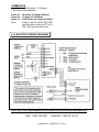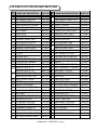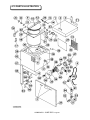
1
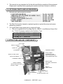
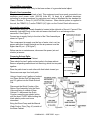
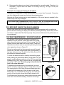
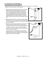
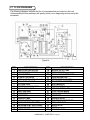
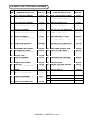
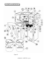
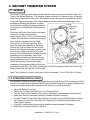
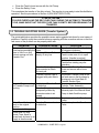
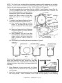
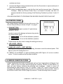
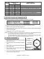
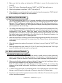
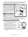
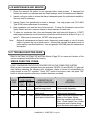
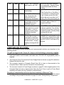
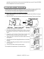
OPERATING AND SERVICE
MANUAL
FOR
SOLVENT RECYCLER AND GUN
CLEANER COMBO SYSTEM
MODEL
EXPLOSION PROOF, AND INTRINSICALLY SAFE
U.S. PATENT No. 4,785,836 & 5,876,567
MANUFACTURED BY
UNI-RAM CORPORATION
ONTARIO, CANADA
COMBO455S – JUNE 2003
CONTENTS
1. GENERAL
PAGE NUMBERS
1.1 INTRODUCTION............................................................................ 3
1.2 WARRANTY REGISTRATION ...................................................... 3
1.3 SYSTEM SPECIFICATION ........................................................... 4
A. SPRAY GUN CLEANER
B. SOLVENT RECYCLER
C. SOLVENT TRANSFER SYSTEM
1.4 ACCSESSORIY KIT ..................................................................... 5
1.5 OPTIONAL PARTS AND ACCESSORIES ................................... 6
1.6 STRUCTURE AND KEY COMPONENTS ..................................... 6
1.7 BEFORE USING ........................................................................... 6
1.8 SET UP AND PREPARATION ...................................................... 7
1.9 WORKING PRINCIPAL ................................................................ 9
2. SPRAY GUN CLEANER
2.1 CLEANING OPERATION INSTRUCTIONS ................................. 10
2.2 OPERATING TIPS......................................................................... 12
2.3 EFFICIENT USE OF GUN CLEANER ........................................... 13
2.4 DAILY MAINTENANCE - SOLVENT LEVELS ............................. 13
2.5 TROUBLE SHOOTING GUIDE ...................................................... 14
2.6 DIAGNOSTIC PROCEDURES ...................................................... 17
2.7 FLOW DIAGRAMS ........................................................................ 18
2.8 PARTS LISTS FOR GUN CLEANER ............................................ 19
2.9 PARTS ILLUSTRATION.................................................................20
3. SOLVENT TRANSFER SYSTEM
3.1 GENERAL .................................................................................... 21
3.2 OPERATING INSTRUCTIONS ................................................... 21
3.3 TROUBLE SHOOTING GUIDE ................................................... 22
COMBO455S – JUNE 2003 - Page 1
4. SOLVENT RECYCLER
4.1 SAFETY .........................................................................................23
4.2 BEFORE USING ............................................................................ 23
4.3 PREPARATION ............................................................................. 23
4.4 CONTROL PANEL........................................................................ 25
4.5 ERROR CONDITION CODES....................................................... 25
4.6 SETTING THE BOILING TEMPERATURE................................... 26
4.7 READY & RUN MODE.................................................................. 26
4.8 DISTILLATION PROCESS ........................................................... 27
4.9 REGULAR MAINTENANCE ......................................................... 27
4.10 MAINTENANCE AND SERVICE................................................. 29
4.11 TROUBLE SHOOTING GUIDE …………………………………… 29
z ERROR CONDITION CODES
z SYMPTOMS AND SOLUTIONS
z FUNCTION CHECK AND CALIBRATION
4.12 FUSE REPLACEMENT PROCEDURES ................................... 32
4.13 ELECTRIC WIRING DIAGRAM .................................................. 33
4.14 PARTS LIST FOR SOLVENT RECYCLER ............................... 34
4.15 PARTS ILLUSTRATION ............................................................ 35
5. SERVICE AND WARRANTY
5.1 WARRANTY REGISTRATION ..................................................... 36
5.2 SERVICE HOT LINE .................................................................... 36
5.3 WARRANTY TERMS ................................................................... 36
WARNING
DO NOT SMOKE, OR USE NEAR AN OPEN FLAME OR SPARKS.
DISCONNECT ALL POWER SOURCES (AIR OR ELECTRIC)
BEFORE PERFORMING MAINTENANCE SERVICE.
DO NOT RECYCLE NITROCELLULOSE! IT IS EXTREMELY
VOLATILE AND MAY IGNITE AT A LOW TEMPERATURE (135 TO
166°C, 275 TO 330°F).
COMBO455S – JUNE 2003 - Page 2
SOLVENT RECYCLER AND GUN
CLEANER COMBO SYSTEM
1. GENERAL
1.1 INTRODUCTION
All UNI-RAM products are engineered and manufactured to the highest performance
standards and have been subjected to detailed testing before shipment from the
factory. However, operator error such as use of inappropriate solvents, incorrect air
pressure, improper service or maintenance etc, could result in malfunction or
damage. Please pay attention to the cautions and warnings provided on labels
attached to this equipment and to those in this manual. Before operating this
equipment, please read the manual. It will help you to operate this equipment safely
and efficiently. Keep it readily available to the operator at all times. If you have any
questions about the operation of this equipment, call your distributor or the Uni-Ram
Product Hot Line:
USA: 1-800-735-4331
Canada: 1-800-417-9133
WARNING
DO NOT SMOKE, OR USE NEAR AN OPEN FLAME OR SPARKS.
DISCONNECT ALL POWER SOURCES (AIR OR ELECTRIC)
BEFORE PERFORMING MAINTENANCE SERVICE.
DO NOT RECYCLE NITROCELLULOSE! IT IS EXTREMELY
VOLATILE AND MAY IGNITE AT A LOW TEMPERATURE (135 TO
166°C, 275 TO 330°F).
1.2 WARRANTY REGISTRATION
1. The standard warranty for this equipment is 12 months from date of purchase by the end
user. An additional extended warranty of 6 months is available free if the Warranty
Registration Card (supplied with this Manual) is properly filled out and returned within 30
days of purchase.
2. Please fill in the space below as a permanent record for warranty purpose.
Supplier
Purchase Date
Invoice No.
Serial No.
Model No.
COMBO455S – JUNE 2003 - Page 3
1.3 SYSTEM SPECIFICATIONS
A. SPRAY GUN CLEANER
1. Timer controlled, automatic, washing of spray guns and paint utensils in less than 60
seconds. Compatible types: siphon, pressure feed, gravity feed.
2. Pushbutton activated, automatic, air flush cycle for removing dirty solvent from internal
cavities and passages.
3. Pushbutton activated, automatic, clean rinse cycle for rinsing both inside and outside of
spray guns and cups with clean solvent. The solvent is followed by a final air flush.
4. Powerful, heavy-duty wash pump specially designed for gun cleaner for long,
trouble-free service.
5. Stainless Steel Rinse pump with metering capability (100 cc) to minimize consumption of
clean solvent and to provide final air purging.
6. All stainless steel cleaning tank and lid for ease of maintenance and durability.
7. Automatic washing, air purging and rinsing of paint feeder hoses.
8. Automatic fume extraction system which is actuated upon opening of the cleaning tank.
9. Wash solvent pail and rinse solvent pail stored safely inside an all-stainless-steel base
cabinet.
B. SOLVENT RECYCLER
10. Fully explosion proof construction and intrinsically safe electric circuitry.
11. Certified by ETL for Class 1, Division 1, Group D, 230°, Under UL2208 CSA 22.2-30, 88
12. A powerful 1,500 Watt heater (100/120V AC, 15/13 Amp.).
13. Efficient direct heating system to eliminate cumbersome changing and disposal of
diathermic oil.
14. Large 5-US gallon (20 liter) distillation tank.
15. Durable, all-stainless-steel, enclosed cabinet safely stores the clean rinse and wash
solvent pails.
16. Fully computer-controlled, automatic distillation with many built-in safety programs.
17. Six Set Point Temperatures are listed below.
RANGE
90°C
115°C
140°C
165°C
190°C
200°C
(194°F)
(239°F)
(284°F)
(329°F)
(374°F)
(392°F)
READY LIGHTS
L
M
H
ON
ON
ON
ON
ON
ON
ON
ON
ON
ON
COMBO455S – JUNE 2003 - Page 4
18. The factory Set Point is 200°C (392° F).
19. Ambient temperature requirement: 5 to 35°C (41 to 95°F).
20. Safety heater thermostat - cuts off heater power if operating temperatures exceeds
220°C (428°F).
21. Safety timer - cuts off heater power after 6 hours of operation.
22. Empty tank safety timer - turns Heater off if boiling does not occur within 60 minutes.
23. Safety thermostat - monitors temperature at the Fan Motor and cuts off motor and heater
power if the temperature exceeds 125°C (257°F).
24. Safety pressure relief system of Tank Lid - prevents pressure higher than 0.5 to 1.0 p.s.i.
(0.03 to 0.06 Bar).
25. Self-Diagnostic System for constant monitoring of all functions. Problems and error
conditions are displayed by means of Error Codes. See page 25 for “Error Codes”.
26. Self-test mode enables the operator to test key functions.
C. SOLVENT TRANSFER SYSTEM
27. Automatic transfer of dirty solvent from gun cleaner unit to solvent recycler unit.
28. Heavy-duty transfer pump for transferring dirty solvent from the gun cleaner to the
solvent recycler and clean solvent back to the gun cleaner.
29. Safety interlock system to prevent accidental transfer when the tank lid is closed.
1.4 ACCESSORIES KIT
1. Check the Accessories you have received. Refer to the list of accessories below. If any
parts are missing, contact the supplier you purchased the equipment from.
Item
1.
2.
3.
4.
5.
6.
7.
8.
9.
10.
11.
12.
13.
14.
NAME AND PART NUMBERS
OPERATING MANUAL
TRIGGER LOCK SPRING
AIR FILTER ASSY
AIR INLET CAP (100-611)
ADAPTER NOZZLE, UNIVERSAL
ADAPTER NOZZLE, SATA
TAPERED PLUG, SIPHON PIPE
TANK LINER BAG
RETAINER FRAME, LINER BAG
LID SEAL GASKET
SOLVENT OUTLET TUBE (SPARE)
SOLVENT PAIL SET, 2 x 5 GALLONS
HOSE CLAMP, TRANSFER HOSE
FUSE KIT
PART NO.
MNL-COMBO455S
120-342
10-220
100-611
110-430
110-430SA
120-572F
LB900C-1
770-9110
770-2150N
770-8131
750-700
100-261
KIT-FUSE5N
GUN
CLEANER
RECYCLER
1 set
3 pieces
1 piece
3 pieces
1 piece
1 piece
1 piece
3 pieces
1 piece
1 piece
1 piece
1 set
1 piece
1 set
2. All Items listed above except item 9 and 12 are packaged in a sealed clear plastic bag.
The Retainer Frame and one Liner Bag are installed in the Recycler’s distillation Tank.
The pails are packed inside the base cabinet.
COMBO455S – JUNE 2003 - Page 5
3. This manual is a very important tool for the safe and effective operation of this equipment.
Please read it carefully before operating the machine and keep it handy for reference.
1.5 OPTIONAL PARTS AND ACCESSORIES
1. Optional parts and accessories include:
FLOW-THROUGH BRUSH .............................................
THREE PAIL SET (ON THREE PAIL MODEL ONLY) ....
FILTER PAD (Pack of 3)..................................................
TRIGGER LOCK SPRING (Pack of 3).............................
LID SEAL GASKET..........................................................
TANK LINER BAG ..........................................................
Part No. 144-399B
Part No. 760-7300
Part No. 100-381/3
Part No. 120-350
Part No. 770-2150N
SEE BELOW
2. The Filter Pad must be cleaned or replaced regularly to protect the pump and ensure
satisfactory operation.
3. It is a good idea to keep spare pads in stock at all times.
• The unit is supplied with a Liner Bag (Part No. LB900C-1) and Retainer Frame (Part
No. 770-9110) already installed inside Distillation Tank.
Liner Bag, 475゜F, Pack of 10
Liner Bag, 475゜F, Pack of 100
Liner Bag, 475゜F, Pack of 250
LB900C-10
LB900C-100
LB900C-250
1.6 STRUCTURE AND KEY COMPONENTS
LID CLAMP
SAFETY COVER
TANK LID
LID GASKET
TRANSFER TIMER
WASH TIMER
CLEANING TANK
AIR FLUSH BUTTON
CLEAN RINSE BUTTON
DISTILLATION TANK
RECYCLER BODY
CONTROL PANEL
SIPHON PIPE
BASE CABINET
SOLVENT TRANSFER
HOSE
RECYCLED SOLVENT
OUTLET TUBE
BRUSH
FOOT PEDAL
SPIGOT
OVERFLOW
FOOT PEDAL
PIPE
RINSE SOLVENT WASH SOLVENT PAIL
PAIL
COMBO455S – JUNE 2003 - Page 6
1.7 BEFORE USING
1. Carefully inspect the shipping carton for any sign of transport damage. Damage to the
carton often indicates transport damage to the equipment inside.
2. Carefully remove the equipment from the shipping carton.
3. Check the equipment, particularly the adjustable legs at the bottom of the unit,
immediately and carefully to ensure that it is not damaged. Report any transport damage
to the carrier without delay to initiate claim procedures. UNI-RAM Corporation is not
responsible for damage to equipment after it leaves our warehouse.
4. Serial Number Labels complying with applicable Marking and Labeling Standards for are
permanently fixed to the inside back of the Base cabinet door. Important information
including Serial Number, Model Number and Air Supply Specification is clearly marked
on the label.
5. Make sure that all markings and labels are not damaged or soiled and are clearly legible.
CAUTION AND REMARKS:
1.
The operator of this equipment should wear protective clothing according to local safety
and environmental regulations, with a minimum of: face goggles, gloves, apron and
respirator.
2.
Avoid inhaling fumes when working with the tank lids open.
3.
Check the Material Safety Data Sheets from your solvent supplier for flammability,
toxicity and boiling points of the solvents you are using.
4.
In case of malfunction during operation of the solvent recycler, the Self Diagnostic
system identifies the problem and the display screen displays error messages as listed
in page 25, Error Condition Codes.
IMPORTANT NOTICE
Always disconnect all power sources (air and electrical) before performing
maintenance service.
1.8 SET UP AND PREPARATION
THIS RECYCLER GUN CLEANER COMBO UNIT MUST BE CORRECTLY
PLACED IN THE WORKSHOP FOR PROPER OPERATION.
Positioning the unit:
• Position unit in a well-ventilated area away from sparks, heat and open flames.
• Make sure that there are at least 6 inches (15 cm) of space all around the unit.
• Set Adjustable Legs to suit floor level and solvent container height.
• Make sure that there is enough space in front of unit for opening the door, positioning
containers and opening the Safety Lid.
• Attach a vent hose (not supplied) to the vent outlet on top of the machine. The duct system
must not be under continuous vacuum. To stop or vary the rate of solvent venting from the
tank upon opening, use the Vent Control Valve on the side of the unit.
COMBO455S – JUNE 2003 - Page 7
Ground Wire connection:
Connect the Ground Wire firmly to the bare surface of a grounded metal object.
Electric Cord connection
The power cord is located at back of unit. This equipment must be properly connected to an
explosion proof power outlet (100/120 Volts AC, 14 Amp) by a qualified electrician,
according to proper procedures for explosion proof units as stipulated by the standard for
Class I, Division 1, Group D. (UL/ETL/CSA) locations. When electric power is supplied to
the unit, the "READY (L)" and/or "READY (H)" light s on the Control Panel will come on.
Air supply connection:
The Air Inlet Fitting (1/4” female threads) is located at the right side of the unit. Connect Filter
assembly (included) firmly to the inlet and ensure that there is no air leakage at the
connection. See Figure 2.
Connect an air supply firmly to the inlet of the Filter Assembly as
shown in Figure 2.
The compressed air supply must be free of water, dust, rust, tar,
grease and other foreign material and the air pressure must be
higher than 85 p.s.i. (5.8 Kg/cm2).
Before service or maintenance, disconnect the power (air and
electric) at source.
Preparing Solvent Pails:
Open the Door of the Base Cabinet.
DRAIN VALVE
There should be two 5-gallon solvent pails in the base cabinet.
Remove all packing material and cut the string, which ties two pails
together.
Place the pails close to each other with their labels toward you.
Remove screw caps from both pails.
VALVE HANDLE
MALE CONNECTOR
Figure 3
Using a funnel, pour 5 gallons of solvent
into Rinse Solvent Pail (left hand side)
and 2.5 gallons into the Wash Solvent
Pail.
Disconnect the Quick Coupler of the
Siphon Pipe Assembly from the Drain
Valve and bring it outside of Base
Cabinet. To disconnect the Quick
Coupler, press the gray plastic button
with the word “PUSH” while holding the
black plastic portion and move
downward.
Bring the Rinse Pump and the Manual
Wash Suction Tube (Tag. #1) outside of
the Base Cabinet.
Figure 2
Figure 4A
COMBO455S – JUNE 2003 - Page 8
Check to ensure that the Drain Valve Handle located under the Cleaning Tank is in the
closed (horizontal) position. See Figure 3.
Insert the Siphon Pipe Assembly into the Wash Solvent Pail (right hand side) through the top
spout.
Insert the Rinse Pump Assembly into the Rinse Solvent Pail (left hand side) through the top
spout (see Figure 4A and 4B).
Insert the Manual Wash Suction Tube (Tag #1) into the hole (Label #1) of the Rinse Solvent
Pail (left hand side) as shown in Figure 4A and 4B.
Place the Solvent Pails
inside the base cabinet so
that the Male Connector
(Figure 3) is aligned with
the top of the Siphon Pipe
Assembly (Figure 4B) and
then connect the Quick
Coupler of the Siphon Pipe
Assembly to the Male
Connector by pushing
hard upward. Turn the
handle of the Drain Valve
to the open position
(vertical).
FIGURE 4B
Connect the Solvent Transfer Hose (Tag #3) to the hose barb (label #3) of the Wash Solvent
Pail as shown in Figure 4 and secure with the Hose Clamp supplied.
Turn the Handle of the Drain Valve to the open (vertical) position and close the Cabinet Door.
NOTE: A SET OF DOUBLE CONTAINMENT PAILS IS AVAILABLE AND OPTIONAL
(NO. 750-9030)
WARNING
DO NOT SMOKE. DO NOT USE NEAR OPEN FLAME, SPARKS OR HEAT.
For maximum safety, wear protective clothing and safety glasses.
1.9 WORKING PRINCIPLES
As explained in Set Up And Preparation (Section 1.8), the Wash Solvent Pail and the Rinse
Solvent Pail are provided inside the base cabinet. The Rinse Solvent Pail should contain 5
gallons (19 liters) and the Wash Solvent Pail should contain 2.5 gallons (9.5 liters) of solvent
when first set up.
During the wash cycle, the main pump will take the dirty solvent from the Wash Solvent Pail
and push it under pressure through many Spray Jets and Nozzles so that the paint debris is
removed from interior passages and the exterior of the spray guns, cups etc. The used
COMBO455S – JUNE 2003 - Page 9
solvent and paint debris will drain into the Wash Solvent Pail.
During the air flush cycle, all used dirty solvent remaining in the interior passage of
the Spray Gun and Spray Manifolds will be evacuated by air pressure and drained
into the Wash Solvent Pail.
During the automatic clean rinse cycle,
approximately 100cc (3.4 oz) of clean solvent is
taken from the Rinse Solvent Pail and pumped
to the spray jets and nozzles and drained to the
Wash Solvent Pail on the right hand side. After
about 95 clean rinse cycles, the Wash Solvent
Pail (half full when first set up) will become full.
During a manual rinse operation, clean solvent
is also transferred to the Wash Solvent Pail.
CONDENSER
To verify the solvent level in the wash pail, you
must check it visually or judge it by the level in
the clean rinse pail. The starting levels in the
Clean Rinse and Wash pails were full and half
full respectively as shown in Figures 4A and 4B.
When the level in the Clean Rinse Pail is low, as
indicated by the Low Level Gauge (Figure 11)
on the Control Panel, the wash pail must be full
as the dirty solvent would have drained into it. It
is now time to transfer wash solvent for
recycling.
During the transfer cycle, activated by the Transfer
Timer, all dirty solvent (maximum 5 gallons) in the Wash Solvent FIGURE 5
Pail is automatically transferred to the Distillation Tank of the Solvent Recycler by the
Transfer Pump in about 2 minutes.
During the distillation cycle, the recycled solvent flows into the Rinse Solvent Pail. When the
Rinse Solvent Pail is full, excess solvent flows into the Wash Solvent Pail through the
over-flow tube. See Figure 5.
2. SPRAY GUN CLEANER
2.1 CLEANING OPERATION
Cleaning Spray Guns and Cups:
1. Any paint left in the Gun Cup should be emptied into a waste paint container for disposal
or recycling before using the machine. Please check your local waste disposal
regulations.
2. Lock the trigger of the Spray Gun in the open position with a Trigger Lock Spring
(supplied). See Figure 8.
3. Open the Lid of the Cleaning Tank and install an applicable Adapter Nozzle (Part No.
110-430 or 110-430SA) onto the Taper Nozzle as shown in Figure 7B.
COMBO455S – JUNE 2003 - Page 10
4. Fit the Paint Inlet of the Spray Gun onto the Adapter Nozzle. See Figure 7B.
5. The Paint Cup of a Gravity or Siphon type Spray Gun may be cleaned by placing it
upside down over the Spray Jets. See Figure 7A.
6. Close the Lid and turn the Timer Knob clockwise to start a wash cycle. The automatic
wash cycle is complete in about 45 seconds.
Automatic Wash
7. Pressurized solvent is pumped through the spray jets and nozzles by the wash pump.
Air Flush
8. Push the Air Flush Button for about 3 seconds to send air through the inside passages of
the Spray Gun and Paint Cup. This helps flush out dirty solvent.
Clean Rinse
9. Push the Clean Rinse Button for about 5 seconds
to rinse the inside passages of the Spray Gun and
Paint Cup with about 100cc (3.4 oz) of clean
solvent
Manual Wash
Manual Rinse
10. When the Foot Pedal on the left side is pressed,
solvent drawn by a Manual Wash Pump from the
Wash Solvent Pail will start flowing out from the
Wash Spigot (left side). Manual wash may be
performed by placing item to be washed in the
solvent flow or by using the Manual Flo-through
Figure 6
Brush (supplied). To use the Manual Brush, first
connect the end of solvent tube (black) to the
spigot as shown in Figure 6. In either case, the solvent used for manual washing will be
re-circulated back to the Wash Solvent Pail.
11. When the Foot Pedal on the right side is pressed, solvent drawn by a venturi from the
Rinse Solvent Pail will start flowing out from the Rinse Spigot (right side). Manual clean
rinse operation may be performed by placing item to be washed in the solvent flow or by
using the Manual Brush connected to the Rinse Spigot as shown in Figure 6. In either
case, the solvent used for manual rinse will be collected into the Wash Solvent Pail. To
control the consumption of the clean solvent to the adequate level while maximizing the
rinse efficiency, a flow of air is introduced with the clean solvent.
Cleaning is now complete.
COMBO455S – JUNE 2003 - Page 11
Figure 7B
2.2 OPERATING TIPS
Before cleaning, remove
excess paint items to be
cleaned.
1. Place
Paint
Cups
upside down over the
low
spray
jets
protruding through the
screen. See Figure 7A.
2. Install the Spray Gun
on to the appropriate
Figure 7A
cleaning nozzle with
the gun facing the corner jets as shown in Figure 7B.
Figure 8
3. Release the Air Cap of the spray gun two full turns and lock the trigger in the open
position with a Trigger Lock Spring. See Figure 8.
4. Guns can be washed with or without the Air Cap installed. The Air Cap can be stored
inside the cleaning cabinet.
5. The Paint Cup Lid of a Gravity Feed Gun may be cleaned on the lid holder.
6. The cleaning tank is not recommended for storage of spray guns.
7. After the cleaning operation has been completed, remove guns and paint cups from the
cabinet and wipe dry.
COMBO455S – JUNE 2003 - Page 12
8. During recycling there is no solvent in the wash pail for two pail models. Therefore, it is
advisable to recycle when the washer is not being used (e.g.: at night, for two pail
models only).
Automatic air purging and rinsing for all models
Press the Air Flush Button or Clean Rinse Button for no more than 5 seconds. Excessive
use of air flushing will cause loss of solvent through atomization.
Although the Rinse function may be used repeatedly, a 30 second pause is needed for the
Rinse Pump to be fully recharged.
IMPORTANT
UNI-RAM RECOMMENDS THE USE OF AN IN-LINE MOISTURE
SEPARATOR FILTER AND LUBRICATOR
2.3 EFFICIENT USE OF THE GUN CLEANER
Always clean spray guns and other related paint utensils immediately after use while the
paint is still wet. To keep your Spray Gun Cleaner operating efficiently, replace dirty solvent
and clean or replace the Filter Pad frequently. Dirty solvent will decrease the performance of
your equipment.
2.4 DAILY MAINTENANCE – SOLVENT LEVELS
MOISTURE FILTER ASSY
The Moisture Filter Assembly (included in accessory kit)
installed to the air inlet has a clear glass bowl and a water
drain valve at the bottom as shown in the drawing. The Filter
collects moisture and water from the air supply. Check the
Glass Bowl and drain water as required by pressing the drain
valve upward as shown in Figure 10.
Glass
Bowl
Solvent is continuously lost by evaporation as well through
normal use. The level in the recycler tank may decrease if it
has been sitting too long. The level in the Clean Solvent Pail
should be also checked regularly.
To check the clean rinse level, carefully observe the gauge
while pressing the Clean Rinse Button. If the level is full, the
gauge’s needle will temporarily rise to the “OK” area and then
fall back to the “LOW” area. If the level is low, the needle will
stay in the “LOW” area. This level gauge only indicates the
level in the clean rinse pail.
Drain Valve
Press to drain.
FIGURE 10
To determine the solvent level in the wash pail, you must
check it visually or judge it by the level in the clean rinse pail.
The starting levels in the Clean Rinse and Wash pails were
full and half full respectively. When the level in the Clean
Rinse Pail is low, as indicated by the gauge, the wash pail
must be full as the dirty solvent would have drained into it.
For efficient use of the recycler, make sure the recycler tank is
more than 75% full before starting. If there is not enough
FIGURE 11
COMBO455S – JUNE 2003 - Page 13
solvent after transferring wash solvent from the wash pail to the recycler tank, add solvent by
pouring it into the recycler tank directly, making sure to stay below the maximum level
indicated by the clamp ring. The recommended level, however, is 1 inch below clamp ring.
When the machine is not in use, drain solvent from the cleaning tank into the solvent
container. Keep the machine and surrounding area clean at all times. Make sure there is no
leakage from the solvent pails. Open the drain to the Solvent container before operating.
2.5 TROUBLE SHOOTING GUIDE (Gun Cleaner)
All air tube connections are provided with Quick Connects for easy disconnection: press and
hold the Release Ring (blue plastic) of the Connector to disconnect. After removing the
Service Cover (detail 3) by removing the 4 screws as shown in Figure 15, most air
connections and components can be accessed easily.
The guide table below provides the possible causes and suggested solutions for most cases
of problems, which may be experienced with the Gun Cleaner unit. Carefully study the
contents before proceeding with the corrective actions so that the real cause of the problem
can be properly dealt with.
PROBLEM
POSSIBLE CAUSE
SOLUTION
No air is supplied to Air Inlet. Supply at least 85psi (6 Kg/cm2)
of air to Air Inlet.
The Safety Cover of the
Close the Safety Cover to
Recycler is not closed.
release the inter-lock valve..
Pump and Timer appear
Low air pressure.
Check air pressure and increase
to be working normally but
to over 85psi (6 Kg/cm2)
there is little or no
Solvent level in Wash
Add solvent to Wash Solvent
washing action.
Solvent Pail is too low
Pail by pouring into Cleaning
Tank of Gun Cleaner.
Filter screen inside Air Inlet
Disconnect air supply and clean
Fitting is clogged with debris. the screen.
Blocked Spray Jets/Nozzle
Remove and clean with air
pressure.
Filter Pad is too dirty.
Clean or replace the Filter Pad.
Drain Valve is closed and
Turn Valve Handle to open
solvent is not draining.
(vertical) position.
Solvent is too dirty.
Replace the dirty solvent.
Suction passage is blocked. Apply air pressure to the bottom
end of the Suction Pipe
Assembly.
The pump is temporarily
Blow the air pressure into the
stalled by excessive water in exhaust pipe of the Manual
air supply,
Wash Pump to back flush the
pump.
Pump is defective and not
Replace or repair Pump.
actually pumping solvent.
Nothing on the gun
cleaner side works.
COMBO455S – JUNE 2003 - Page 14
PROBLEM
POSSIBLE CAUSE
Pump and Timer are
working but Inside
passage of Spray Gun is
not cleaned.
SOLUTION
Trigger Lock Spring is not
Install Trigger Lock Spring,
properly installed or Paint
release Air Cap 2 full turns and
valve of Spray gun is closed. repeat cleaning cycle. Make
sure Paint Valve is open.
Spray Gun is not properly
Make sure the Gun is firmly
installed onto Cleaning
installed and not too loose on
Nozzle.
cleaning nozzle. Use suitable
Nozzle Adapter as required.
Pump is not working, air is Pump is defective.
Repair or replace the pump.
escaping from top
Excessive water in air supply Blow air into the exhaust pipe to
exhaust pipe.
caused the pump to stall
back flush the pump
Pump and Timer are
Pump has a defective
Replace or repair Pump.
working but solvent is
diaphragm.
leaking around Tank Lid. Air pressure is too high.
Make sure the pressure
regulator (inside) is adjusted to
the correct pressure of 75 PSI.
Solvent is not draining
Drain Valve under Tank is
Open Drain Valve. (Handle
from Tank.
closed. (Handle is horizontal) should be in vertical position.)
Solvent is not draining
Filter Pad is too dirty.
Clean or replace Filter Pad.
from Tank.
Piece of cloth, paper, plastic, Remove Filter Pad and Work
etc. is blocking drain hole at Screen and clean the bottom of
the bottom of Tank.
Tank.
When Timer Knob is
Timer mechanism is
Replace defective Timer.
turned clockwise, it spins defective.
back to the original
position.
Timer is not clicking.
Pump does not stop,
unless Timer Knob is
turned back by hand or air
supply is disconnected.
Cleaning Function is
Rinse Pump is
Repair or replace the Check
working well but Clean
malfunctioning
Valve Assembly of the Rinse
Rinse does not work.
Pump
Clean Rinse Air Valve is
Repair or replace the Rinse Air
defective.
Valve Assembly
Excessive air leakage into Check Valve located at the
Repair or replace the Check
clean solvent when Rinse bottom of the Rinse Pump is Valve Assembly of the Rinse
Button is pressed.
leaking.
Pump
During washing operation, Combination Valve Assy is
Repair or replace the One-Way
dirty solvent is moving into dirty with debris or defective Check Valve Assembly in the
clean solvent pail.
and leaking.
Combination Valve.
(A poppet valve is defective
or has come out of Coil
Spring).
During washing cycle,
One-way Check Valve in the Repair or replace the One-Way
solvent is leaking from Air Combination Valve is
Check Valve Assembly in the
Rinse Valve. –
defective and leaking.
Combination Valve.
COMBO455S – JUNE 2003 - Page 15
PROBLEM
POSSIBLE CAUSE
Manual Wash Pump does The pump is temporarily
not work when the Wash stalled by excessive water in
Foot Pedal (left side) is
air supply,
pressed.
The Manual Wash Suction
Pipe in the Wash Solvent Pail
is blocked by thick paint or
debris.
The Manual Wash Pump is
defective.
Wash Foot Pedal Air Valve
(left side) is defective.
Manual rinse does not
The Manual Rinse Suction
work when the Rinse Foot Pipe in the Rinse Solvent Pail
Pedal (right side) is
is blocked by debris or some
pressed.
object.
The Manual Rinse Venturi is
clogged or defective.
SOLUTION
Blow the air pressure into the
exhaust pipe of the Manual
Wash Pump to back flush the
pump.
Clean out the suction passage of
the Suction Pipe.
Repair or replace the Manual
Wash Pump.
Repair or replace the Wash Foot
Pedal Air Valve Assembly.
Clean out the suction passage of
the Rinse Suction Pipe.
Clean the Manual Rinse Venturi.
Venturi has no moving part and
is not likely break-down.
Rinse Foot Pedal Air Valve
Repair or replace the Rinse Foot
(right side) is defective.
Pedal Air Valve Assembly.
Fume extraction system is The Adjuster Screw on Lid
Adjust screw on Lid Switch
still working when Tank
Striker Plate is out of
Plate. Loosen the Lock Nut and
Lid is closed.
adjustment.
turn Screw clockwise slowly until
Fume Extraction System stops
while lid is closed.
Safety Lid Switch is defective Repair or replace the Lid Switch
and malfunctioning.
Air Valve Assembly.
“Fish-eye” type damage to Contamination of paint
Replace all solvent with new. Do
new paint finishes
thinners by mineral spirits or not mix paint thinners and
other solvents containing
incompatible solvents or use
“oily” or “wax” components.
containers. Be especially
Cleaning clothes in contact
careful where paint thinners are
with mineral spirits, wax or
used in the same area as parts
other “oily” solvents was
washer solvents.
used.
COMBO455S – JUNE 2003 - Page 16
2.6 DIAGNOSTIC PROCEDURES
When the Pump does not work and there is no obvious malfunction (e.g.: excessive air
leaking out of the air exhaust), try the following:
1. Disconnect the air hose to the pump air inlet or Timer Air
Outlet by pressing the Release Ring. Turn the Timer
“ON”. If air blows out of the Timer when the Timer is
turned on and stops when the Timer is turned off, the
Timer is working well but the Pump may be defective.
Using a Hand Blow Gun, apply air pressure to the air
hose leading to the Air Inlet of the Pump. If the Pump
works normally, there may be a kink or blockage in the air
line.
2. When the Pump and Timer are working normally and the
Solvent Pail is full, but no solvent comes out of the Spray
Jets, either the pump is defective or the suction line before
the pump is blocked.
Figure 12
3. Disconnect the Suction Pipe Assembly from the bottom of
the Tank. Check the suction vacuum of the Pump by
closing the suction inlet of the Suction Pipe Assembly with
your fingers as shown in Figure 12 while the Pump is
working. If no vacuum is felt, the Pump is defective and
must be repaired or replaced.
If a good vacuum is felt, the Pump is normal and the
problem may be due to a blockage in the solvent hose or
the spray jets. Blow air into the Suction Hose as shown in
Figure 13 to clear out the blockage.
Figure 13
COMBO455S – JUNE 2003 - Page 17
2.7 FLOW DIAGRAMS
The following diagrams indicate the flow of compressed air and solvent in this unit.
Understanding the flow pathways will greatly assist you in diagnosing and servicing this
equipment.
Figure 14
ITEM
1
2
3
4
5
6
7
8
9
10
11
12
13
14
15
16
16A
17
DESCRIPTION
FUME EXTRACTION SYSTEM
FUME EXTRACTION VENTURI
AIR INLET FITTING
LID SAFETY AIR VALVE
SAFETY COVER TRANSFER AIR VALVE
CLEAN RINSE AIR VALVE
AIR FLUSH VALVE
FOOT PEDAL, MANUAL WASH
MANUAL WASH VALVE
WASH TIMER ASSY
SIPHON PIPE ASSY
SUCTION PIPE
TRANSFER TIMER
WASH SOLVENT PAIL
DIAPHRAGM PUMP, TRANSFER
DIAPHRAGM PUMP, GUN CLEANER
DIAPHRAGM PUMP, MANUAL WASH
OVER FLOW PIPE
ITEM
18
19
20
21
22
23
24
25
26
27
28
29
30
31
32
33
34
35
DESCRIPTION
SOLVENT OUTLET TUBE
RINSE PUMP ASSY
MANUAL WASH SUCTION TUBE
CLEAN SOLVENT PAIL
COMBINATION VALVE ASSY
TANK BOTTOM CONNECTOR
SPRAY MANIFOLD
TAPERED NOZZLE
WIDE ANGLE SPRAY JET
FLOW THROUGH BRUSH
MANUAL RINSE VENTURI
CONDENSER
TRANSFER VALVE
TRANSFER SOLVENT OUTLET
DISTILLATION TANK
VAPOR OUTLET
SPIGOT
LOW LEVEL GAGE
COMBO455S – JUNE 2003 - Page 18
2.8 PARTS LIST FOR GUN CLEANER
ITEM
1
2
3
4
5
6
7
8
9
10
11
12
NAME AND DESCRIPTION
MECH. TIMER ASSY, MANUAL
MECH. TIMER CONTROL KNOB
ACCESS PANEL
MECH. TIMER ASSY, MANUAL
RINSE VALVE ASSY
MANUAL SIPHON ASSY, UG4VFM
LID SWITCH ASSEMBLY
STRIKE PLATE ASSEMBLY
TRIGGER LOCK SPRING (3 PACK)
LID OR DOOR HANDLE
NOZZLE ADAPTER TUBE ASSY
AIR SUPPLY PLUG
13 FLOW-THROUGH BRUSH
14
15
16
17
18
19
21
22
22
23
24
25
26
27
28
29
PART NO.
ITEM
115-200/2
115-260F
760-4111
115-200
115-400B
140-270
114-800V
100-810A
120-350
120-318
110-430SA
115-450
30
31
32
33
34
35
36
37
38
39
40
144-399B
PAINT CUP HOLDER
LID ASSEMBLY WITH HANDLE
LID OPENING STOP ARM
TANK COMPLETE, SS, CENTRE
DELIVERY TUBE
SPRAY JET ASSEMBLY
RINSE SOLVENT HOSE
FRAME RETARD. SCREEN
FILTER PAD
SIPHON GUN CLEANER NOZZLE
CABINET
DOOR
PEDAL ASSY, FOOT SWITCH
DRAIN VALVE ASSEMBLY
HOSE, THINNER-RESIST, 3/8ID
TANK BOTTOM CONNECTOR
100-413F
140-320V
120-337S
760-3310
100-360
100-350
140-855
140-332S
100-380
110-356
760-6200S
760-6300S
100-750
10-171
RBH38X1116
100-456
41
42
43
44
45
46
47
48
49
50
NAME AND DESCRIPTION
QUICK COUPLING NIPPLE (MALE)
MANUAL WASH SUCTION TUBE
SOLVENT SUCTION PIPE ASSY
RINSE VALVE ASSY, FOOT
TRANSFER SUCTION PIPE
PAIL, GUN CLEANER, 5 GAL.
PAIL ONLY, W/O LID, WASH SOLV.
SPILL CONTAINMENT PAIL
OVERFLOW PIPE, PAILS
RINSE PUMP ASSY., 1 VALVE
LID CLAMP RINSE, PAIL LID
PAIL, RECYCLER, 5 GAL.
PAIL ONLY W/O LID, RINSE SOLV.
OUTLET TUBE, COPPER, URS500
HOSE CLAMP, #4, INSIDE TANK
OUTLET PE TUBE, URS500
COMBINATION VALVE BLOCK
DIAPHRAGM PUMP, GUN WASH
DIAPHRAGM PUMP, TRANSFER
LOW LEVEL GAGE
PUSH BUTTON, RINSE, MOLDED
RINSE VALVE ASSY
51 CONTROL BOX, SS
53
54
55
82
COMBO455S – JUNE 2003 - Page 19
PART NO.
120-421
140-271
140-500
112-500F
750-720
750-710G
750-712G
100-041
750-751
URP100-C
750-713
750-710R
750-712R
600-8121
100-261S
600-8131
UVB400KIT
UDP4TA
UDP4TA
167-470U
140-731F
115-400B
760-410S
2.9 PARTS ILLUSTRATION
Figure 15
COMBO455S – JUNE 2003 - Page 20
3. SOLVENT TRANSFER SYSTEM
3.1 GENERAL
The Solvent Transfer System automatically transfers dirty solvent from the Wash Pail to the
Tank of the Solvent Recycler. This transfer system consists of a Transfer Pump, a Transfer
Timer and a Transfer Shut Off Valve. The transfer system will operate only when the Safety
Cover and Tank Lid are open. This feature helps to prevent overfilling and damage to the
machine by allowing the operator to make
sure that the Liner Bag is properly installed in
the Tank and to observe the transfer process
directly.
Each time the Clean Rinse button is pressed
to perform a clean rinse operation,
approximately 100cc (3.4 oz) of clean solvent
is taken from the Rinse Solvent Pail on the left
hand side and transferred to the Wash
Solvent Pail on the right hand side. After
about 95 clean rinse operations, the Wash
Solvent Pail (half full when first set up) will
become full. Manual rinsing also moves clean
solvent to the Wash solvent Pail. The dirty
solvent in the Wash Solvent Pail must now be
transferred to the Distillation Tank of the
Solvent Recycler and recycled according to
the procedures provided in the next section.
When the recycling operation has been
completed, the recycled solvent will flow into
the Rinse Solvent Pail. If the Rinse Solvent pail overfills, the excess solvent will flow into the
Wash Solvent Pail through the over-flow pipe.
Note: Total volume of solvent in both pails should not exceed 7.5 to 8.0 Gal (28 to 30 liters).
3.2 OPERATING INSTRUCTIONS
The distillation operation should be performed when the Wash Solvent Pail has become full. At
this point, the rinse solvent pail should be half full and efficient rinsing is no longer possible even
though the washing and air flush operations will continue to function normally.
•
•
•
•
•
Open the Safety Cover fully.
Unlock the Lid Clamp and open the Lid of Recycler Tank.
Turn the lever of the Transfer Valve counter clockwise by 90 degrees as shown below.
Make sure that the Liner Bag is properly installed and that it is empty.
Turn the Transfer Timer Knob fully clockwise. The dirty solvent will start flowing out from
the Transfer Port into the Liner Bag. The transfer will be stopped automatically by the
Timer after 2 minutes.
• Close the Transfer Valve by turning the handle counterclockwise 90 degrees.
• Add solvent to the full level if it is still low.
COMBO455S – JUNE 2003 - Page 21
• Close the Tank Lid and secure with the Lid Clamp.
• Close the Safety Cover.
This completes the transfer of the dirty solvent. The recycler is now ready to start the distillation
operation. See the procedures in Section 4 (SOLVENT RECYCLER).
CAUTION:
TO AVOID OVERFILLING THE RECYCLER TANK DURING THE AUTOMATIC TRANSFER
CYCLE, MAKE SURE THAT THE RECYCLER TANK IS EMPTY BEFORE BEGINNING THE
TRANSFER
3.3 TROUBLE SHOOTING GUIDE (Transfer System)
The guide table below provides the possible causes and suggested solutions for most cases of
problems. Carefully study the contents before proceeding with the corrective actions so that the
real cause of the problem can be properly dealt with.
PROBLEM
Pump and Timer appear
to be working normally but
there is little or no dirty
solvent coming out from
Transfer Port.
Transfer Timer is working
but Transfer Pump is not
working.
When Timer Knob spins
back to the original
position.
Timer is not clicking.
Pump does not stop,
unless Timer Knob is
turned back by hand or air
supply is disconnected.
POSSIBLE CAUSE
Transfer Valve is not fully
open.
Washing Solvent Pail is
empty or very low.
SOLUTION
Turn the Handle of Transfer Valve
90 degrees clockwise.
Check Drain Valve of Cleaning
Tank to make sure it is in open
position. (Handle is vertical)
Add more solvent into Distillation
Tank before starting recycler
operation.
Transfer Suction Hose is
Connect the Transfer Suction
disconnected at Wash
Hose and secure with a hose
Solvent pail.
clamp.
Transfer Suction Pipe is
Disconnect Transfer Hose at the
clogged with paint debris.
pail and remove the blockage by
blowing air into Hose Barb of
Transfer Suction Pipe.
Air Valve of Transfer Timer Repair or replace Air Valve or
is defective.
Transfer Timer Assembly.
Transfer Pump is
Blow the air pressure into the
temporarily stalled by
exhaust pipe of the Manual Wash
excessive water in air
Pump to back flush the pump.
supply,
Transfer Pump is defective. Repair or replace the Transfer
Pump.
Transfer Timer mechanism Repair or replace the Transfer
is defective.
Timer.
COMBO455S – JUNE 2003 - Page 22
4. SOLVENT RECYCLER
4.1 SAFETY
Solvent recycler incorporated in this combo unit is engineered and manufactured to the
highest performance standards and has been subjected to detailed testing before
shipment from factory. This unit is also certified by ETL (Electric Testing Laboratory) to
be EXPLOSION PROOF CLASS 1, DIVISION 1, GROUP D – T2C, UNDER UL2208
STANDARDS AND CSA C22.2 No.30 and is the one of the safest equipment of this kind.
However, operator error such as use of inappropriate solvents, incorrect use of Liner
Bag, wrong temperature setting, improper service and maintenance etc, could result in
malfunction, damage or accident. Pay serious attention to all cautions and warnings
provided on labels affixed on this equipment as well as in this manual. Before operating
this equipment, please carefully read this manual, which is a key to the successful and
safe operation of this equipment. Keep this manual in good care and in place readily
available to operator at all times. If you have any questions about the operation of this
equipment, call your distributor or the UNI-RAM Product Hot Line:
USA: 1-800-735-4331
Canada: 1-800-417-9133
CAUTION
DO NOT USE THIS EQUIPMENT TO RECYCLE PARTS WASHER SOLVENTS. “FISH
EYE” DEFECTS MAY BE CAUSED WHEN PAINT OR LACQUER THINNER IS
CONTAMINATED WITH PARTS WASHER SOLVENTS.
4.2 BEFORE USING
•
•
The unit is supplied with a Liner Bag (Part No.LB900C-1) and Retainer Frame (Part No.
770-9110) already installed inside Distillation Tank.
Two more Liner Bags (Part No. LB900C-1) are also supplied with this equipment as spares,
but please order before you run out, using the table below.
Liner Bag, 475゜F, Pack of 10
Liner Bag, 475゜F, Pack of 100
Liner Bag, 475゜F, Pack of 250
LB900C-10
LB900C-100
LB900C-250
MAKE SURE EXCESS LINER BAG MATERIAL DOES NOT BLOCK VAPOR OUTLET OF
RESERVOIR TANK.
4.3 PREPARATION
When the Wash Solvent Pail becomes full, transfer the dirty solvent from the Wash Solvent Pail
to the Distillation Tank according to the procedures described in section 3.2 OPERATING
INSTRUCTION (PAGE 21).
The capacity of the tank is 20 liters (5.0 US gallon). A minimum of 6 liters (1.5 US gallon) is
recommended.
Do not overfill the tank or dirty solvent will flow into the Condenser and cause blockage,
discoloration of distilled solvent etc.
COMBO455S – JUNE 2003 - Page 23
NOTE: The Tank Lid is provided with an automatic pressure relief mechanism as a safety
measure. In the event of a pressure increase inside the Tank, the Safety Pressure Relief
System will start releasing pressure at 0.5 to 1.0 PSI (0.035 to 0.070 kglcm2)
1
The unit is supplied with a Liner Bag (Part No. LB900C-1) and Retainer Frame (Part No.
770-9110) installed in the Tank. The Liner Bag may be used several times. However, the
life of the bag depends on several factors
including the type of solvent, temperature
settings etc. When reusing a Liner Bag,
make sure that it is not damaged or
leaking.
2
To install a Liner Bag and Retainer Frame,
follow the procedures described below:
(a) First, install Liner Bag so that the
bottom of the Bag sits flat on the
bottom of Reservoir Tank. (See Figure
1)
(b) Insert your fingers into loop of Retainer
Ring and squeeze to reduce diameter
as shown in Figure 2.
(c) Insert Retainer Ring into Liner Bag
inside Reservoir Tank and release two
fingers to that it will sit just above the
step of Reservoir Tank as shown in
Figure 3.
(d) Fold down lip of Liner Bag all around as shown in Figure 4.
Observe safety precautions noted in item 1, 2, and 3
above, and carefully pour dirty solvent into Liner Bag
inside Reservoir Tank. Keep Reservoir Tank clean by
making sure that no dirty solvent is poured outside of the
Liner Bag.
3. Close Reservoir Lid and secure with Lid Clamp.
Make sure that the Reservoir Lid is firmly seated to
avoid leakage.
4. Open Door and place an approved solvent collecting container (20 liter or 5 US gallon) in
the area provided. Insert Condenser Outlet Tube into top opening of the collecting
COMBO455S – JUNE 2003 - Page 24
container as shown.
5. Connect the Alligator clamp provided at the end of the Ground wire to expose metal part of
the solvent receiving container.
NOTE: Adjust the adjustable legs to suite the floor level and the type and size of Receiving
Container. Make sure Solvent Outlet Tube is not kinked or blocked, and that it is
properly inserted into the top opening of the Receiving Container by at least 1 inch (2.5
cm).
YOU ARE NOW READY TO PROGRAM THE ENCORE SOLVENT RECYCLING UNIT.
4.4 CONTROL PANEL
The Control Panel is located at the top right corner of the
Solvent Recycler Body as shown in Figure 1 on page 6.
1. PUSH BUTTONS:
The keypad control panel consists of 2 push buttons
labeled as follows:
In order to prevent the damage and ensure long service
life, press buttons gently.
(1)
0
To turn off the distillation operation.
(2)
I
To turn on the distillation operation.
These buttons are also used to change the boiling point set up.
2. LED LIGHTS - READY:
See page 4.
3. OTHER LED LIGHTS – HEAT AND FAN:
HEAT light is on; the heater is on. If it is flashing, the heater is on at the reduced power. FAN
light is on; the unit Cooling Fan is on.
4. If READY (H) and READY (L) lights are flashing when HEAT light is off, en error condition
exists. The error conditions are described as below:
4.5 ERROR CONDITION CODES
A SELF DIAGNOSIS FEATURE IS PROVIDED WITHIN THE COMPUTER SYSTEM OF THE
UNIT. When an error has been detected during the operation, READY (H) and READY (L)
lights will start flushing indicating the following error conditions. Heater is turned off
automatically for safety except in code “22” condition. Press “OFF” button to stop error code,
and press “ON” button to resume operation after error condition has been corrected. Refer to
the ERROR CONDITION CODES (Page 29) section of Trouble Shooting Guide for details.
COMBO455S – JUNE 2003 - Page 25
ERROR
CODE
11
12
21
22
23
24
31
32
33
FLUSHING OF LED
LIGHTS
READY (H) READY (L)
1 TIME
1 TIME
1 TIME
2 TIMES
2 TIMES
1 TIME
2 TIMES
2 TIMES
2 TIMES
3 TIMES
2 TIMES
4 TIMES
3 TIMES
1 TIME
3 TIMES
2 TIMES
3 TIMES
3 TIMES
DESCRIPTION OF
ERROR CONDITIONS
Tank Thermocouple is defective and has open circuit.
Condenser Thermocouple has open circuit.
Heater Circuit has open circuit due to broken fuse.
Heater Triac is defective and Heater is still “ON”
Condenser is overheating.
Code 23 condition lasts over 10 minutes.
Tank is either empty or not enough solvent.
Reset occurred due to power interruption.
Recycling not finished in 6 hours.
4.6 SETTING THE BOILING TEMPERATURE
Three boiling temperature settings are available as indicated by LED lights:
“READY (L)” LED LIGHT IS ON
>>>>>>>>>>>>>>
“READY (H)” LED LIGHT IS ON
>>>>>>>>>>>>>>
“READY (L)” & “READY (H)” ARE ON >>>>>>>>>>>>>>
150°C (302°F)
200°C (392°F)
175°C (347°F)
To change the temperature setting, follow the procedures as described below:
1. Make sure that "HEAT" and "FAN" lights are off.
2. Press and hold "OFF" button. Press "ON" button once or twice to obtain desired setting as
indicated by LED lights.
3. Release both "OFF" and "ON" buttons together.
NOTE: All temperature settings are indications for the start point of the boiling phase and will
vary according to the solvent used and the extent of contamination.
The dirty solvent often includes different types of oil, which have boiling points higher
than 200°C (392°F), the highest temperature attainable in this unit.
4.7 READY & RUN MODE
1.
Open Reservoir Tank Lid and Install Lining Bag
and Retainer Frame.
2.
Pour used solvent into Lining Bag in Reservoir
Tank.
3.
Close Tank Lid, secure with Lacking Clamp and
close Outer Cover.
4.
Open Cabinet Door and place clean, empty
solvent container inside.
5.
Lift and insert Solvent Outlet Tube into spout of
Solvent Container and close Door
COMBO455S – JUNE 2003 - Page 26
6. Make sure that the setting as indicated by LED lights is correct for the solvent to be
recycled.
7. Press “ON” button. Recycling will start and “HEAT” and “FAN” lights will come on.
8. When boiling phase is completed, “HEAT” light will go off.
9. When distillation is completed and the unit is cooled to the safe temperature, “FAN” light will
go off indicating unit is ready for the next operation
4.8 DISTILLATION PROCESS
1.
The initial heating phase takes 10 to 15 minutes, depending on the volume and the boiling
point of solvent being distilled, room temperature, etc. During this process, both "HEAT"
Light and "FAN" Light are on, indicating that the Heater and the Fan Motor are turned on.
"READY (L)" and/or "READY (H)" LED Light(s) also flash(es) indicating which of the six set
point temperatures the unit is using.
2.
The boiling phase begins when the temperature reaches typical boiling temperature of the
solvent being processed. This temperature will vary with solvent type and the extent of
contamination of that solvent. During this phase, most of the heat goes into vapor
generation with no increase or only a small temperature increase at the thermo-sensor and
the distilled solvent starts dripping from the outlet tube into the Receiving Container at a
rate of 2.5 to 3.0 gallons (9.5 -11.5 liters) per hour.
3.
When the components of the dirty solvent with boiling temperature lower than the set-point
temperature have all evaporated, the temperature at the Thermo-Sensor starts increasing
more rapidly.
4.
When the temperature reaches the set point, the Heater is turned off and the "HEAT" Light
goes off.
5.
When the temperature goes down to 60°C (144°F), the Cooling Fan stops and "FAN" Light
goes off, indicating the unit is ready for next process.
4.9 REGULAR MAINTENANCE
PROCEDURE FOR REPLACING LINER BAG:
1. Even when a liner bag is used to collect the residue, a small amount of clean solvent will
remain in the bottom of the Reservoir because of condensation of solvent at the end of
boiling phase. Clean the Reservoir Tank with a brush and clean damp cloth after each use.
2. When pouring the dirty solvent, make sure that all of it goes into the Liner Bag so that no
dirty solvent gets between the Liner Bag and Reservoir Tank.
Note: To avoid scratches and other damage to the Reservoir Tank, do not clean with
abrasives or hard metal instruments. Use plastic or wooden tools to clean out residues if
necessary.
3. To ensure a long service life of Lid Gasket (Part No. 770-2150N) and also to prevent vapor
leakage, carefully clean the inside edge of Reservoir where the Lid Gasket seats.
4. Keep the area around the equipment clean and clear of all debris. Do not store the recycled
solvent inside the equipment.
COMBO455S – JUNE 2003 - Page 27
5. Always use the Bag Retainer Frame (Part No. 770-9110) supplied with the unit, when using
the liner bag (Part No. LB900C-1). Remove Residue from Linger Bag, clean bottom of
Solvent Reservoir; check Liner Bag to determine if can be reused without leakage.
PROCEDURES FOR CLEANING THE CONDENSOR:
Condenser must be checked regularly and
cleaned as required to ensure that it is free of
dust and debris. Dust and debris collected on
the opposite side of the condenser are not
visible through the Upper Screen in the back
of the unit. If the condenser is over-heating
due to the excessive dust, the operation will
stop and LED Lights will show either of two
error codes 23 or 24. To clean the dirty
condenser, blow off the dust by air blowgun
as shown in the illustration on the right or use
vacuum cleaner.
PROCEDURES FOR REPLACING LID
GASKET:
Lid Gasket (Part No. 770-2150N), which is
exposed to high temperature and solvent
vapor during the distilling process, is subject
to normal wear.
Before the Lid is closed, make sure that the top inside edge of the of the Reservoir Tank where
Lid Gasket seats is completely wiped clean to be free of any paint or dirty solvent.
This will greatly prolong the life of the Lid Gasket. When leakage of solvent vapor due to wear or
damage is found, the Lid Gasket must be replaced with a new one as soon as possible.
REPLACE LID GASKET BY THE FOLLOWING PROCEDURES:
1. Open the Reservoir Tank Lid.
2.
Hold the top of Lid in open position by left hand and
loosen Center Screw by 3 complete turns with a
Philip Screw Driver. Inner Plate and Lid Gasket will
come loose from Outer Plate of Lid.
3.
Remove the defective Lid Gasket. Install a new Lid
Gasket (Part No. 770-2150N) into the groove
between Outer Plate and Inner Plate of the Lid.
Care should be taken not to scratch Lid Gasket.
4. Make sure that Lid Gasket is evenly stretched all
around and tighten Center Screw completely. This
completes the Lid Gasket replacement.
Note: It is recommended to keep a few Lid Gaskets (Part No. 770-2150N) in stock as
spares.
COMBO455S – JUNE 2003 - Page 28
4.10 MAINTENANCE AND SERVICE
1. Check the reservoir lid gasket for any damage before each process. A damaged Lid
Gasket can result in an improper seal and Vapor leakage, which is hazardous and wasteful.
2. Inspect cooling air outlet to ensure that there is adequate space for undisturbed ventilation.
Vacuum clean if necessary.
3. Inspect Power Cord periodically for wear or damage. Use only proper cord (16/3 AWG
Type SOW) when replacement is necessary.
4. Keep condenser coils and fins free of dust and dirt. To clean the Condenser, remove the
Upper Screen and use a vacuum cleaner to clean between fins and coils.
5. To clean out condenser tube, close two threaded side inlet holes with fingers or 1/4"NPT
male plugs and place air nozzle into bottom outlet hole and flush with air at about 30 p.s.i. (2
kg/cm2). Make sure to remove two 1/4"NPT male plugs used.
Note:
Before all maintenance and service work, disconnect power supply or turn off at main
switch to prevent the risk of electrocution. All electrical services and repairs must be
performed by a certified electrician. Use only genuine UNI-RAM parts for maintenance
and repairs.
4.11 TROUBLE SHOOTING GUIDE
Refer to the Parts List (Page 34) and Parts Sketch (Page 35) for name and location of the
various component mentioned in this section.
ERROR CONDITION CODES:
A SELF-DIAGNOSIS FEATURE IS PROVIDED WITHIN THE COMPUTER SYSTEM.
When an error has been detected during the operation, READY (H) and READY (L) lights will
start flashing indicating the following error conditions. Heater is turned off automatically for
safety except in code “22” condition. Press “OFF” button to stop error code, and press “ON”
button to resume operation after error condition has been corrected.
ERROR
CODE
11
12
21
FLUSHING OF
LED LIGHTS
READY
READY
(H)
(L)
1 TIME
1 TIME
DESCRIPTION OF
ERROR CONDITIONS
Tank Thermo is defective
and has open circuit.
1 TIME 2 TIMES Condenser Thermo has
open circuit.
2 TIMES 1 TIME Heater Circuit has open
circuit due to broken fuse.
ACTION
REQUIRED
Repair or replace Tank
Thermocouple Assembly.
Repair or replace Condenser
Thermocouple Assembly
A short circuit has occurred in the
Heater or the Heater Wiring.
Check the condition with a circuit
tester. Check Heater Fuse, Heater
Thermostat and/or heater wiring.
Repair the defect and replace Fuse.
COMBO455S – JUNE 2003 - Page 29
22
2 TIMES 2 TIMES Heater Triac is defective
and Heater is still “ON”
23
2 TIMES 3 TIMES Condenser is
overheating.
24
2 TIMES 4 TIMES If code 23 condition last
over 10 minutes, this
code will show and
operation is terminated.
3 TIMES 1 TIME Tank is either empty or
not enough solvent and
boiling did not occur
within 45 minutes.
3 TIMES 2 TIMES Micro Controller has
been reset due to power
interruption, or drop in
voltage of power supply
during the recycling
operation.
3 TIMES 3 TIMES Recycling not finished in
6 hours due to power
interruption or because
the set point was too low
for the solvent. Usually
nothing is wrong with the
unit.
31
32
33
Disconnect the power supply as
soon as possible. Replace Power
Control Board inside the Motor
Housing.
Clean dirty Condenser. (See page
28)
Check Cooling Fan or Fan Motor. If
the Condenser is overheating due
to lack of space around the unit,
position the unit to provide 4 to 6
inches (10 to 15cm) around the unit.
Check Tank to make sure that there
is at least 1 gallon (4 liters) of
solvent in the Tank.
Press “OFF” and then “ON” buttons
to resume operation. Turn off the
Electricity at the source for about 30
seconds if possible. Usually nothing
is wrong with the unit.
Raise Set Point and try again.
If “READY (H)” setting did not work,
the solvent has boiling point higher
than 200°C(392°F) and cannot be
recycled.
SYMPTOMS AND SOLUTIONS:
Some of the possible trouble symptoms and recommended solutions are described in the
following section.
The unit is plugged in but “Power On” lamp is not lit indicating no electricity supplied
1. There is no power is supplied to the electrical receptacle to which the unit is plugged. Check
main fuses and/or circuit breaker and make sure 100/120V AC single-phase power is
supplied.
2. The Computer Fuse (F3) located on Power Supply Board as shown on page 32 is defective.
Replace the defective fuse.
3. The connector located on Computer Board (Item #5) is loose or disconnected at the
Computer Board. Make sure the Terminal is connected firmly.
4. The connector located on Power Supply as shown on page 32, which supplies power to the
Computer Board is loose or disconnected. Open the Front Cover to pull out Power Board
Assembly and make sure the Connector is inserted firmly.
Recycling is completed but still a lot of solvent remaining in Reservoir Tank
1. Boiling temperature setting is too low. Raise the set temperature as required for the solvent
according to the procedures described on page 26 under “Setting Boiling Temperature".
COMBO455S – JUNE 2003 - Page 30
2. The solvent to be recycled contains too much oil or other contamination, which make the
boiling temperature higher. Raise the set point if possible. Some solvent has boiling point
higher than 200°C(392°F) and cannot be recycled by this unit.
Thinner vapor leaking from Lid Gasket
1. Lid Gasket (Item 10) has excessive wear, crack or
other defect. Replace the defective Lid Gasket.
Follow the procedures on page 28 of the Operation
Manual.
2. Reservoir Tank (Item #21), around top edge where
Lid Gasket is seated, is scratched, dented or
otherwise damaged causing leakage. Repair the
defect or replace Reservoir Tank Assy as required.
4.
Reservoir Lid (Item #9) is not positioned correctly in relation to the Reservoir Tank. Adjust
the Lid by loosening the two hex bolts on the Tank Lower Hinge (Item #13). Close the Lid in
the correct position and tighten two bolts firmly.
Liner Bag is burnt or melting
Liner bag of lower quality does not withstand the high temperature. Make sure that genuine
Uni-ram Liner Bags are used. See page 23 for the correct part numbers of liner bags.
Computer seems to malfunction
If the Computer should appear to malfunction, causing strange symptoms, it could be due to
power interruption, or drop in voltage of power supply during the recycling operation.
Discontinue the power supply by unplugging or by turning off main power switch or
Breaker for one minute, reinstate the power supply and operate the unit again.
If this has not solved the problem, contact us for further advice.
“Fish Eye” Problem
If mineral sprit such as the Parts Washer Solvents, Varsol, etc. has been introduced into the
equipment, the distilled solvent may be dirty with such mineral spirit, causing “Fish Eye”
problems in the paint finish. It may be necessary to distill 5 to 10 gallons of paint or lacquer
thinner to remove contamination.
FUNCTION CHECK AND CALIBRATION:
The functions and performance of the unit may be checked easily by following the procedures.
This test is useful if some malfunction is suspected.
Note: Water absorbs heat energy much more than the solvents and takes much longer to
recycle. If the unit works we// with water, it means it will work faster with solvent.
1. Remove the Liner Bag and the Retainer Frame from the Reservoir tank.
2. Fill the Reservoir Tank with 1 to 2 gallons (7.6 to 15 liters) of clean water.
3. Set the Set-Point temperature to READY (L) range which will provide the highest boiling
temperature of 150°C (302°F).
Note: READY (L) light is on before the unit is turned on and flashing during the operation.
4. Run the unit until the water has been almost completely distilled.
5. If however, the water is still remaining in the tank when the unit has automatically turned
itself off, it could indicate that a temperature off-set has occurred and calibration may be
COMBO455S – JUNE 2003 - Page 31
required to correct the off-set or that some technical defect has occurred. Contact UNI-RAM
Service Department for the service instructions.
4.12 FUSE REPLACEMENT PROCEDURES
A Snap ring Pliers is not required to remove the Front Cover of Motor Housing as shown below.
Fuse may blow due to power surge, lightning, and shock during transportation, etc.
To prevent shock, disconnect power supply before starting these procedures.
Replace the fuse according to the following procedure
1. Three Fuses are located on the Power Control Board mounted inside the Motor Housing as
shown on the right.
2. Open Front Doors, and remove screen covering the motor housing. The front end of Motor
Housing is now exposed for service work.
3. Remove the Snap Ring from the front end of Motor Housing
by pulling two curved ends of Snap Ring closer with your
fingers.
4. Using pliers, grab the Head of Center Screw located on the
Front Cover Assy as shown below and pull out gently.
6.
Check each fuse to locate the fuse that has been burnt out
and replace it.
7.
Carefully push the Power Supply Board back into the Motor
Housing.
8.
Install the Snap Ring and make sure that it is securely locked
into the groove.
9.
Close the Door and connect the power supply.
This completes the replacement of the defective fuses.
COMBO455S – JUNE 2003 - Page 32
COMBO455S
100/120V AC, 50/60 Cycles, 13/15 Amps
1,500 Watts Heater Element
Fuses F1: 20.0 Amp. for Heater Element
Fuses F2: 1.0 Amp. for Fan Motor
Fuses F3: 0.0625 Amp. for Computer Board
Note:
Fuses F1 and F3 are 250 VAC 3AG
type fast action fuses and F3 is 25
VDC 3AG type fast action fuse.
4.13 ELECTRIC WIRING DIAGRAM
CALL THE TOLL FREE NUMBERS LISTED BELOW FOR FURTHER INFORMATION
USA: 1-800-735-4331
CANADA: 1-800-417-9133
COMBO455S – JUNE 2003 - Page 33
4.14 PARTS LIST FOR SOLVENT RECYCLER
ITEM
NO.
1
2
3
4
5
6
8
9
10
11
12
13
14
15
16
17
18
19
20
21
22
23
24
25
26
27
28
29
30
31
32
33
34
35
NAME AND DESCRIPTION
ITEM
PART NO. NO.
OUTER SAFETY COVER ASSY
770-3310
PULL HANDLE, DOOR & LID
120-318
STAY, SAFETY COVER
770-3370
FRONT SCREEN (NOT SHOWN)
760-6278
COMPUTER ASSY, URS5/600
600-3450
SWITCH PANEL
600-3461
POWER CORD
500-4700
TANK LID ASSY
770-2100
LID GASKET, BLACK, 70DU
770-2150N
FRICTION PLATE, LID STAY
770-3730
LID HOLDER BAR ASSY
700-2230
U-BRACKET LOWER HINGE
770-2251
HINGE PIN BOLT, 1/4"-20X4.5”L
99-436HH
HEX BOLT
99-406SS
LID CLAMP ASSY
900-2220
FRONT CLAMP CATCH, SS
770-2261
COVER, HEATER TERMINAL
960-1365
RETAINER RING, SS
770-9110S
LINER BAG, PACK OF 10
LB900C-10
LINER BAG, PACK OF 100
LB900C-100
TANK & HEATER ASSY, 120V
500-1100
TANK & HEATER ASSY, 240V
600-1100
VAPOR OUTLET FITTING
770-1151L
HEX NUT
100-463
TRANSFER VALVE ASSY
750-3300
FLARE ELBOW, 3/8"NPT-1/2"T
Z50-8B
HEX LOCK NUT, HINGE PIN, 3/8"
99-543DH
BACK PANEL
600-3131
REAR SCREEN ASSY(NOT SHWN) 600-3140
SIDE INSULATOR PAD
600-1210
BOTTOM INSULATOR PAD
770-1230
CONDENSER & TUBE ASSY
600-5100
CONDENSER THERMOSTAT
900-5152
HEATER THERMOSTAT
960-1830
FRONT COVER, MOTOR HOUSING 600-4320
SNAP RING, HOUSING COVER
600-4131
36
37
38
39
40
41
42
43
44
45
46
47
48
49
50
51
52
53
54
55
56
57
58
59
60
61
62
63
64
65
66
67
68
NAME AND DESCRIPTION
PART NO.
POWER BOARD, URS500, 100V
500-4310
POWER BOARD, URS600, 120V
600-4310
DOOR ASSY
760-6300S
SCREW ¼”-20X5/8”L
99-404SR
CONNECTOR, COMPUTER CORD 770-4283
CONNECTOR, POWER CORD
770-4284
SEALING FITTING, 1/2"NPT
770-4286
CLOSE NIPPLE, ½”NPTX1”L
10-179
REDUCER ADAPTER
Z123-CB
MOTOR HOUSING TUBE
600-4110
FAN MOTOR ASSY, 120V
500-4210
FAN MOTOR ASSY, 240V
600-4210
REAR COVER, MOTOR HOUSING 600-4115
FAN, 5-BLADE, 8"OD, CCW
600-4230
SNAP RING, MOTOR SUPPORT
600-4133
770-4282
½” ELBOW 90°,GAL(NOT SHWN)
HEX NUT
100-463
WIRE, HEATER - PWR BOARD
770-4810
WIRE, THERMOSTAT - PWR BRD
770-4820
UNION ASSY, 1/2"NPTx2
700-4283
LONG NIPPLE, 1/2"NPTX 6"L
10-421
DOOR LOCK
960-3230
ELBOW, 90D, BRASS
Z9139-6B
UNION NIPPLE, HEX
110-473
PE OUTLET TUBE, CONDENSER
600-8131
WIRE, THERMOSTAT - HEATER
770-4850
OUTLET TUBE, COPPER
600-8121
ADJUSTABLE FOOT
110-531L
O-RING, MOTOR SUPPORT
600-4137
OUTLET TUBE GUIDE
600-3129
HOSE CLAMP, 1/2"ID.SS, #4
100-261S
GROUND WIRE WITH CLIP
148-8830
RECYCLER BODY
760-3112
CROSS MEMBER
760-6230S
BASE CABINET ASSEMBLY
760-6210S
COMBO455S – JUNE 2003 - Page 34
4.15 PARTS ILLUSTRATION
COMBO455S – JUNE 2003 - Page 35
5. SERVICE AND WARRANTY
5.1 WARRANTY REGISTRATION
Please refer to Page 3, General, and 1.2 Warranty Registration.
5.2 SERVICE HOT LINE
Call the toll free numbers listed below for further information.
USA: 1-800-735-4331
CANADA: 1-800-417-9133
5.3 WARRANTY TERMS
WARRANTY
This UNI-RAM product has been manufactured and engineered to high performance standards, and
has been subject to detailed factory test before shipment.
12 Month Warranty Complete Unit
It is warranted by UNI-RAM for twelve (12) months from established purchase date. UNI-RAM
Manufacturing will repair or replace, free of charge, to the original purchaser any parts found to be
defective in material of workmanship as determined by factory service personnel, with the exception of
the replaceable items listed below under “Condition of Warranty”.
Service labour to install such parts will be supplied without charge for this twelve-month period, at our
factory. The complete unit must be returned to the UNI-RAM Factory or approved Service Centre,
transportation pre-paid, together with a letter of explanation.
Service and Parts:
In connection with Service Labour required to repair or replace parts after this twelve-month period will
be based on the service labour rate and the parts prices effective at the time of repair.
Conditions of Warranty:
Since UNI-RAM have no control over the working conditions, materials involved and the
circumstances under which the purchaser stores, handles, or uses the product, we make no warranty
or condition, either expressed or implied with respect to this product, or its fitness for any purpose; or
the result to be obtained from its use; other than instructions provided. No representative of Uni-Ram
Corporation or their Distributors has the authority to waive or change this provision, which applies to all
sales.
These warranties apply only to the original purchaser and do not apply if the unit has been misused,
subjected to overloading, neglect, wear or accident, altered or used for any purpose other than
according to the operating and installation instructions provided, or subjected to fire, floods, or other
acts of God.
These warranties do not cover transportation, interior or exterior finishes, pump packing, O-rings and
seals, screens, filters, nozzles, or air jets or unit with serial number altered or removed.
The use of unauthorized chemicals or solvents with acid content in this unit shall render this warranty
null and void.
Use only UNI-RAM RECYCLING BAGS. These high temperature and chemical resistant bags are
tested to Uni-ram specifications and approved by Uni-ram Corporation to contain recycling solvents in
the distillation tank. Use of bags not approved by Uni-ram Corporation can void the warranty of the
Uni-ram solvent recycler.
Attempts at self-repair or alterations by the owner shall also constitute a violation of these warranty.
COMBO455S – JUNE 2003 - Page 36