1
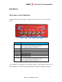
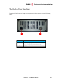
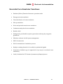
CAEN Tools for Discovery n Electronic Instrumentation DT5800D Dual Channel Desktop Digital Detector Emulator with channel correlation Getting Started and Operating Manual September 2013 CAEN Electronic Instrumentation CAEN S.p.A. Via Vetraia, 11 55049 Viareggio (LU) - ITALY Tel. +39.0584.388.398 Fax +39.0584.388.959 [email protected] www.caen.it © CAEN SpA – 2013 Disclaimer No part of this manual may be reproduced in any form or by any means, electronic, mechanical, recording, or otherwise, without the prior written permission of CAEN SpA. The information contained herein has been carefully checked and is believed to be accurate; however, no responsibility is assumed for inaccuracies. CAEN SpA reserves the right to modify its products specifications without giving any notice; for up to date information please visit www.caen.it. CAEN S.P.A. – DT5800D User Manual 2 CAEN Electronic Instrumentation Table of Contents How This Manual Is Organized ................................................................ 5 Calibration ..................................................................................................................................... 5 System Recovery and Update ................................................................................................. 5 Reference........................................................................................................................................ 5 Safety Instructions ....................................................................................... 6 Symbols ........................................................................................................................................... 6 Precautions .................................................................................................................................... 6 Operating Environment ............................................................................................................ 7 Cooling ............................................................................................................................................. 7 Cleaning .......................................................................................................................................... 7 Calibration ..................................................................................................................................... 8 Power ............................................................................................................................................... 8 Hardware......................................................................................................... 9 The Front of Your Emulator .................................................................................................... 9 The Back of Your Emulator .................................................................................................. 10 Essential Core Emulator Functions...................................................... 11 Running the Software ............................................................................... 12 Installation .................................................................................................................................. 12 Program Execution .................................................................................................................. 13 First Run ...................................................................................................................................... 14 One Touch Interface ................................................................................................................ 17 Setting Area ................................................................................................................................ 18 Main Settings ............................................................................................................................................................ 19 Channel 1 Mode / Channel 2 Mode ........................................................................................................... 20 Run / Debug ........................................................................................................................................................ 20 Spectrum Quantization .................................................................................................................................. 21 Connector Router.............................................................................................................................................. 22 CH 1 / CH 2 ................................................................................................................................................................ 25 General settings ................................................................................................................................................. 28 Energy Mode ....................................................................................................................................................... 29 Signal Shape ........................................................................................................................................................ 36 Multi-Shape ......................................................................................................................................................... 44 Shape Interpolator ........................................................................................................................................... 46 Time Distribution ............................................................................................................................................. 47 Pile-up .................................................................................................................................................................... 50 Noise Emulation ................................................................................................................................................ 52 Interference ......................................................................................................................................................... 53 Baseline Drift ...................................................................................................................................................... 54 LSFR Settings ...................................................................................................................................................... 57 Sequence ...................................................................................................................................... 58 Correlated Events ................................................................................................................................................... 61 Timing Settings .................................................................................................................................................. 62 Statistical Settings ............................................................................................................................................ 62 Climatic Operating Condition ...................................................................................................................... 64 Display Area ............................................................................................................................... 65 CSV File Format......................................................................................................................... 67 Shape ............................................................................................................................................................................ 67 Spectrum .................................................................................................................................................................... 67 CAEN S.P.A. – DT5800D User Manual 3 CAEN Electronic Instrumentation Time distribution .................................................................................................................................................... 68 Interference ............................................................................................................................................................... 68 Signal Generator ...................................................................................................................................................... 68 Sequence in Energy Mode and in Time Distribution .............................................................................. 69 Calibration ................................................................................................... 70 System Recovery and Update ................................................................ 72 CAEN S.P.A. – DT5800D User Manual 4 CAEN Electronic Instrumentation How This Manual Is Organized We cover your instrument's unique hardware and software features in the sections: Hardware Essential Core Functions User Interface Calibration The Calibration of the Emulator is described in order to be performed in total autonomy by the end user with the only support of a multimeter and of the internal fully automatic procedure, which is initialized through a file available on nuclearinstruments.eu and on the mass storage support delivered with the instrument. A guideline is provided. System Recovery and Update No problem if a failure occurs in the firmware of the system or if an update is requested. The system recovery and update procedure is fully automatic and no needs human attendance. Reference The Reference section is set aside and covers items like Certifications, how to contact CAEN for Support, and to always maintains the most current specification information. The website should always be checked for updates. CAEN S.P.A. – DT5800D User Manual 5 CAEN Electronic Instrumentation Safety Instructions This section contains instructions that must be observed to keep the instrument operating in a correct and safe condition. You are required to follow generally accepted safety procedures in addition to the precautions specified in this section. The overall safety of any system incorporating this instrument is the responsibility of the assembler of the system. Symbols This symbol appears in the instrument's documentation to alert you to important safety considerations. CAUTION of potential damage to instrument, or WARNING of potential for bodily injury, or system malfunctions. Attend to the accompanying information to protect against personal injury or damage. Do not proceed until conditions are fully understood and met. Precautions Use proper power supply. Use only the power supply shipped with this instrument and certified for the country of use. Connect and disconnect properly. Do not connect/disconnect leads while they are connected to a current/voltage source. Observe all terminal ratings. Do not apply a voltage to any input that exceeds the maximum rating of that input. Use only within operational environment listed. Do not use in wet or explosive atmospheres. Use indoors only. Keep product surfaces clean and dry. Do not block the cooling vents. Leave a minimum six-inch (15 cm) gap between the instrument and the nearest object. Keep the underside and the upper side clear of papers and other objects. Do not remove the covers or inside parts. Refer all maintenance to qualified service personnel of CAEN. CAEN S.P.A. – DT5800D User Manual 6 CAEN Electronic Instrumentation Do not operate with suspected failures. Do not use the product if any part is damaged. In case of incorrect behaviors, cease operation immediately and sequester the instrument from inadvertent use. Operating Environment Temperature: 5 to 40 °C. Humidity: Maximum relative humidity 80 % for temperatures up to 31° C decreasing linearly to 50 % relative humidity at 40° C (or at the upper operational temperature limit). Altitude: Up to 10,000 ft (3,048 m) at or below 25° C. Cooling The instrument relies on forced air cooling with internal fans and vents. Take care to avoid restricting the airflow to any part of the instrument. Around the sides and rear, leave a minimum of 15 cm (6 inches) between the instrument and the nearest object. At the bottom, the emulator feet (up or down) provide adequate clearance. CAUTION. Do not block emulator vents. Always keep the area beneath the emulator clear of paper and other items. Cleaning Clean only the exterior of the instrument using a damp, soft cloth. Do not use harsh chemicals or abrasive elements. Under no circumstances submerge the instrument or allow moisture to penetrate it. Unplug the power before cleaning. CAUTION. Do not attempt to clean internal parts. Refer to qualified service personnel of CAEN. CAEN S.P.A. – DT5800D User Manual 7 CAEN Electronic Instrumentation Calibration The instrument is calibrated at the factory prior to being shipped. The recommended calibration interval is five years. Calibration can be performed by the end user through the included automatic calibration function, which is initialized through a file available on nuclearinstruments.eu and on the mass storage support delivered with the instrument. Extended warranty, calibration, and upgrade plans are available for purchase. Contact CAEN sales representative to purchase a service plan. Power Use only the power supply shipped with this instrument and certified for the country of use. All I/O digital gates are LVCMOS compliant. The dynamic range of the analog outputs is 4.4 V @ 50 output impedance and 8.8 V @ high impedance. CAEN S.P.A. – DT5800D User Manual 8 CAEN Electronic Instrumentation Hardware The Front of Your Emulator Numbered labels on the image correspond with descriptions on the following table. 1 8 2 Number 1 2 3 4 5 6 7 8 3 4 5 6 7 Description Blue LED – Analog output CH1 status Active low intensity: normal operation Active high intensity: saturation Analog output CH1 Digital input CH1 Digital output CH1 Digital output CH2 Digital input CH2 Analog output CH2 Blue LED – Analog output CH2 status Active low intensity: normal operation Active high intensity: saturation CAUTION. All I/O gates are LVCMOS compliant. The dynamic range of the analog outputs is 4.4 V @ 50 output impedance and 8.8 V @ high impedance. CAEN S.P.A. – DT5800D User Manual 9 CAEN Electronic Instrumentation The Back of Your Emulator Numbered labels on the image correspond with descriptions on the following table. 1 Number 1 2 2 Description Power Supply Connector (+12 V central terminal positive) USB Interface Connector CAEN S.P.A. – DT5800D User Manual 10 CAEN Electronic Instrumentation Essential Core Emulator Functions Emulator/Pulser/Function Generator operation mode Energy spectrum emulation Time distribution of events emulation Pile-up emulation Noise and periodic interference emulation Continuous and pulsed reset emulation Baseline drift Debug mode: predictable sequence generation with step-by-step pulse generation Windows software for full system management USB 2.0 connection DLL for automation of emulation process Replay on analog channels of recorded or synthetized signals Generation of shifted copy of a signal with 11 ps step (i.e. correlated event emulation) Load / download in CSV format of parameters/shapes/spectra CAEN S.P.A. – DT5800D User Manual 11 CAEN Electronic Instrumentation Running the Software Installation Do not connect the Emulator before you install the software CAEN DOCK. On the PC where you decide to host the system, login as Administrator and run NuclearInstrumentsDock_Setup . If driver installation fails, you can install them manually from the ‘Drivers’ folder on the mass storage support delivered. CAEN S.P.A. – DT5800D User Manual 12 CAEN Electronic Instrumentation Program Execution When the program is opened, lists all available Emulators connected to the system bus with both USB and Ethernet. If the emulator is not listed check the connection and press ‘Scan Now’. If you do not have hardware connected you can start the software in simulation mode by checking ‘SOFTWAREEMULATOR’. Identified the emulator verify that the program has put the check mark next to the name. Then press ‘Connect All’ and wait for the physical connection attempt to the hardware. The GUI start corresponds to the end of the process. The whole operation could take up to 30’’. CAEN S.P.A. – DT5800D User Manual 13 CAEN Electronic Instrumentation First Run The first time the software runs, you must import the calibration file. The software automatically detects the absence of it and advances a query for loading. The file is contained in the ‘Calibration’ folder on the on the mass storage support delivered. In case of failure of the file research, the standard calibration procedure described in the Section ‘Calibration‘ can be executed. The function “Get From Web” allows downloading on the host the calibration parameters related to your DDE from the website detectoremulator.com. CAEN S.P.A. – DT5800D User Manual 14 CAEN Electronic Instrumentation User Interface The picture shows the main panel of the User Interface. The interface is partitioned in two main distinct areas plus a fast control panel and a report line fixed at the bottom of the display. The report line returns the true generation conditions of both channels, labeled as A and B. In particular: - In (cps) : Ideal number of events that should be generated in accordance with the programmed statistic. - Out (cps) : Number of events actually generated that is limited due to pile-up or to saturation of the output analog stage in case of “analog exponential”. - Live (%) : - Counts Ratio between the number of pulses that should be generated and the number of events actually generated. : Generated event counter resettable through the button by side. The virtual LED turns to red color when the programmed statistic of generation is no more feasible due to pile-up limit or to saturation of the output analog stage in case of “analog exponential”. On the left side of the display are all the settings that initialize and control each channel of the instrument (Setting Area). On the right side the actual CAEN S.P.A. – DT5800D User Manual 15 CAEN Electronic Instrumentation configuration of the Emulator is shown by means of graphs for each channel (Display Area). CAEN S.P.A. – DT5800D User Manual 16 CAEN Electronic Instrumentation One Touch Interface After starting the software, the panel “One Touch Interface” is available for quick handling of the instrument. Through a series of virtual knobs, the main parameters of signal generation of the two channels can be regulated. Rate, amplitude and exponential shape can be controlled. The controllable noise is only white. The number of piled up pulse is fixed at 16 events. The panel can be switched off and activated anytime through the command in top left corner of the main display. CAEN S.P.A. – DT5800D User Manual 17 CAEN Electronic Instrumentation Setting Area The setting area of the main panel has five menus: Main Settings. Control of the main functions of the instrument. CH1. Control of specific settings of Channel 1 CH2. Control of specific settings of Channel 2 Sequence. Management of reproduction of recorded sequences Correlated events. Definition of delay properties in the generation of correlated events. CAEN S.P.A. – DT5800D User Manual 18 CAEN Electronic Instrumentation Main Settings CAEN S.P.A. – DT5800D User Manual 19 CAEN Electronic Instrumentation Channel 1 Mode / Channel 2 Mode Both Channel 1 (CH 1) and Channel 2 (CH 2) can independently operate as Emulator/Pulser or Sequence Player. In the Emulator/Pulser mode, the instrument generates a statistic or deterministic sequence of pulses. In the Sequence Player mode, the instrument loads from the outside the sequence of pulses that reproduces. Run / Debug The operative conditions are free-running (default mode at start-up) and stepby-step debug. The free-running of emulation is based on the generation of pseudo-random numbers by means of Linear Feedback Shift Registers (LFSR). The randomness of the seed value starting the generation process ensures the emulation of different sequences, even if in agreement with the set statistical characteristics. From the other side, fixing the seed value (in CH1 and CH2 menus) allows to generate always the same identical sequence. This is at the basis of the step-bystep debug. After setting a value of the seed, the generation process starts and evolves either free-running or one step at a time. CAEN S.P.A. – DT5800D User Manual 20 CAEN Electronic Instrumentation In this latter mode, by enabling the LFSR control flag (as in the picture above), the LSFRs can be stopped and then made switching for one clock cycle. During the LSFRs freezing, the output is still present and corresponds to the last generated pulse that is repeated iteratively. In the meanwhile the LSFRs are paused, the reset command can be used to reset the status of the LSFRs that returns to the seed value set initially. After resetting, the same former sequence is re-generated either in free-running or step-by-step mode . Alternatively, by enabling the Time Base Generator control flag, the debug procedure stops the time base generators, which operatively means that the generation of pulses is inhibited and can be activated to produce a pulse at a time at the output of the emulator. If reset is asserted when the generation is stopped, the LFSRs are reset and the sequence can be started back from the beginning equal to itself either in free-running or pulse-by-pulse mode. The Multistep mode consists in responding to the command with the generation of an a-priori fixed number of pulses (16 in the picture above). After the packet of pulses is produced, the instrument enters in stand-by mode with the same possible evolution of the other operative conditions. Spectrum Quantization It is well known that the re-quantization of a spectrum over a different number of bins introduces distortions in its shape due ultimately to an aliasing effect. The spectrum emulated should have resolution in bins equal to the number of bins of the target device that reconstructs it from the emulated pulses. As a rule, the reference spectrum in the emulator has resolution above the request one. In order to get the matching of bin resolution, a decimation process is implemented in the instrument with three possible processing procedures. The spectrum is divided in windows of equal amplitude automatically calculated on the basis of the target resolution and for each window the first bin or the bin CAEN S.P.A. – DT5800D User Manual 21 CAEN Electronic Instrumentation with highest number of counts is taken as result of the decimation. Third way of decimation is consider only the first part of the spectrum over a number of bins congruent with the target resolution. Connector Router The emulator front-end consists of six configurable I/O ports, analog and digital. The picture shows the configuration sheet for I/O digital settings. CAUTION. All I/O gates are LVCMOS compliant. The dynamic range of the analog outputs is 4.4 V. Input 1 / Input 2. All signals are considered normally in the low LVCMOS state and active in correspondence of transitions to high LVCMOS state. - - Disable : disabling of the gate Gate 1 / Gate 2 : the internal trigger of pulses is put in AND with an external signal of trigger S Gate 1 / S Gate 2 : the Strong Gate signal inhibits instantaneously the output signal Trigger 1 / Trigger 2 : the pulse generation is synchronized with the switching of the input signal. Care should be paid to the uncertainty in the generation time due to the sampling period of the input signal equal to 8 ns Run/Stop : on/off control of the internal LFSRs (remote control of and ) Step Over : generation process advanced by one step (remote control of ) Reset LFSR / Restart Memory : reset of the status of the LSFRs that returns to the seed value set initially (remote control of ) Baseline Reset (B ) : reset of the value of the baseline CAEN S.P.A. – DT5800D User Manual 22 CAEN Electronic Instrumentation CAEN S.P.A. – DT5800D User Manual 23 CAEN Electronic Instrumentation Digital Out 1 / Digital Out 2. Outputs are pulses with duration defined in the field Pulse width (ns) of the Connector Router mask (see picture above). The electrical standard is LVCMOS. - Disable : disabling of the gate Trigger : the direct output of the time-base generator, independently on the finalization of generating a correspondent pulse Accepted Trigger : the direct output of the time-base generator that corresponds to the actual generation of the correspondent pulse. This means one Accepted Trigger pulse for every analog pulse at the output ON/OFF : state of activation of the channel Machine Overloaded : no more availability of generation engines, which means excess of pile-up. The signal is asserted high until the condition persists Analog Saturation : saturation of the dynamic range of the analog output (below screenshot of Analog Saturation digital signal – green – correspondent to the saturation of the analog output – red) CAEN S.P.A. – DT5800D User Manual 24 CAEN Electronic Instrumentation CH 1 / CH 2 CAEN S.P.A. – DT5800D User Manual 25 CAEN Electronic Instrumentation CAEN S.P.A. – DT5800D User Manual 26 CAEN Electronic Instrumentation CAEN S.P.A. – DT5800D User Manual 27 CAEN Electronic Instrumentation General settings Channel Enable. If selected the output is activated. Otherwise the output is fixed to zero with low impedance. Equivalent to the main button OUTPUT ENABLE. Anti-alias filter. Insert a RC filter on the output of the DAC to improve signal shape. Output filter. Insert an LC 7th order filter on the output to improve noise suppression. Rise time of the output signal is 16ns. Invert. If selected the polarity of the output is changed. Digital Gain. Digital amplification of the output signal between 0 and 2. Digital Offset. Reference offset expressed as a fraction of 216 levels of quantization, i.e. between -2.2 V and +2.2 V that is applied before the gain stage. Pulsed Reset Detector. If selected, the output of a pulsed reset detector is emulated. The output is a staircase whose dynamic is limited by the fields Minimum Value (minimum -32767 levels corresponding to -2.2 V) and Maximum Value (maximum 32768 levels corresponding to +2.2 V). It is possible to scale the output signal setting the Minimum number of events that at full amplitude saturate the dynamic of the staircase. CAEN S.P.A. – DT5800D User Manual 28 CAEN Electronic Instrumentation Energy Mode The emulation modes are Pulser, i.e. generation of pulses with amplitude and time distribution fixed RTG – Random Tail Generator, i.e. generation of pulses with fixed amplitude and pseudo-random statistical time distribution Emulator of Radiation Sources, i.e. generation of pulses statistically distributed whose spectrum corresponds to a given starting spectrum Pulser – Select the flag Single Line and adjust the slider position to regulate the amplitude of the pulses at the output. In the panel box Time Distribution set the constant value of the rate by means of the slider, from 10-2 cps to 5 Mcps. RTG – Random Tail Generator – Select the flag Single Line. In the panel box Time Distribution select the flag File and indicate a time distribution of the pulses, i.e. the probability of occurrence of the successive pulse after a certain time. For instance, loading the exponential time distribution implies that is maximum the probability of occurrence of next pulse after one clock period, i.e. 8 ns. Emulator of Radiation Sources – Select the flag Spectrum Emulation and load a reference energy spectrum and a time distribution in the panel box Time Distribution. CAEN S.P.A. – DT5800D User Manual 29 CAEN Electronic Instrumentation The reference spectrum can be loaded (‘Load File’ button) as a .csv file (see Section CSV File Format) ANSI N4242, result of an experimental measurement or a Matlab© synthesis. The Spectrum Import Tool allows the upload of the spectrum in .csv or N4242 format. CAEN S.P.A. – DT5800D User Manual 30 CAEN Electronic Instrumentation In presence of multiple N4242 spectra, the command window “Spectrum Available” allows selecting the desired source. The tool allows to adjust the dynamic of the input spectrum to the resolution of 16384 bins of the instrument. Both a scaling and an offset regulation are available. By checking the “Interpolate” button, the scaling is performed by means of a linear interpolation, otherwise each new bin is created on basis of the nearest value of the bin on the left. The function of “Adj Peak” sets the highest peak of the input spectrum at the value 65535. The spectrum can be generated internally to the Emulator. The tool for the internal generation is run by the ‘Preset’ button. The internally generated spectrum can be edited by the procedure ‘Edit’. The button ‘Remove’ resets the actual reference spectrum. The picture shows the screen shot of the interface of the ‘Spectrum Editor’ tool. CAEN S.P.A. – DT5800D User Manual 31 CAEN Electronic Instrumentation The tool allows to design a spectrum of lines. Rectangular or Gaussian widening can be introduced for each line that is centered in the bin ‘Channel’ and has height equal to the correspondent value in ‘Counts’. An arbitrary number of lines can be introduced (‘+’) and deleted ( ‘–‘). The synthetized spectrum can be saved as .spectrum file. The spectrum is represented on a scale with maximum resolution of 14 bits, while the resolution of the Emulator is 16 bits. A scale factor is present to adjust the spectrum resolution to the instrument range, e.g. Scale x2 for spectrum with resolution of 14 bits. CAEN S.P.A. – DT5800D User Manual 32 CAEN Electronic Instrumentation The picture shows a screen shot of the output of the emulator initialized as in the example above with the spectrum of the isotope 60Co. Through the “Isotopes DATABASE” menu, it is possible to select from the periodic table of elements one of the isotopes of each atom. Among all correspondent X and Gamma spectral lines, a set is created and is added in the spectrum under synthesis with the specification of the relative activity. The operation can be repeated aggregating an arbitrary number of elements. Finally, the energy calibration is performed by setting the energy in keV unit corresponding to 0 V, the energy corresponding to the full scale of 2 V, and the desired resolution in eV unit. The resolution equal to 0 eV corresponds to monoenergetic lines. CAEN S.P.A. – DT5800D User Manual 33 CAEN Electronic Instrumentation The ‘Sequence’ option allows to load the amplitudes of an a-priori defined sequence of pulses. The same option is in the section ‘Time Distribution’ and allows the loading of the correspondent temporal distances between the pulses. In this way, it is possible to emulate repetitively the stored sequence made up to 500 kpulses. Also a partially defined sequence can be stored. The following combinations are available. Load sequence of amplitudes but time distribution at constant or statistical rate Load sequence of temporal distances but amplitudes constant or statistically generated as above described CAEN S.P.A. – DT5800D User Manual 34 CAEN Electronic Instrumentation All features of the emulation process (noise, signal shape, …) are active except the generation of amplitudes from a spectrum. The picture shows a screenshot of stored amplitude sequence. CAEN S.P.A. – DT5800D User Manual 35 CAEN Electronic Instrumentation Signal Shape The emulator is able to generate both exponential signals and signals of arbitrary shape. The exponential signal is generated through the cascade of two IIR filters. The first one sets the time constant of the exponential shape and the second one adjusts the rise time. For the analogy with an analog pulser, this operation mode is referred as “Analog (RC)”. The maximum number of piled-up events is limited only by the saturation of the analog output stage and the Poisson statistical distribution of the events is guaranteed at any rate. The generation of signals of arbitrary shape is realized by means of 16 memories of 4096 points each. Signals longer than 4096 points can be obtained with a linear interpolator available at the output of each memory. If piled-up events exceed the maximum number of 16, the statistical distribution of the output events is not more Poissonian. In this case the virtual LED on the report line fixed at the bottom of the display turns to red color indicating that the programmed statistic of generation is no more feasible. By default, the emulator generates an exponential signal with rise-time and falltime adjustable by the user. The block “Analog RC operates at a frequency equal to half the system clock and is therefore not capable of generating correctly signals with time constant and/or rise time shorter than 16 ns. The system is initialized in the “Auto” operation mode and automatically selects between “Fast” and “Analog (RC)” mode depending on the values of time constant and rise time programmed by the user. The “Fast” mode uses 16 memories to generate the exponential signal. After setting the time constants of rise and fall of the signal, the system automatically CAEN S.P.A. – DT5800D User Manual 36 CAEN Electronic Instrumentation implements the shape and activates the interpolators (if necessary) choosing the most suitable interpolation factor. This signal is referred “analog exponential” and is different from the “fast exponential” among the preset shapes. After setting the time constants of rise-time (trise) and fall-time (τ), the system automatically implements the shape and activates the interpolators (if necessary) choosing the most suitable interpolation factor. This feature is not available with the Multishape operating mode. The generation flow of the exponential shape is the cascade of the following steps. 1. An ideal exponential shape is generated according to the definition { ( ) 2. The shape pass through a first-order IIR low-pass filter with bandwidth equal to . 3. The system calculates the sample in correspondence to which the filtered shape at full-scale gets off below the LSB of the DAC. 4. On this basis, the system calculates the factor of subsampling: 500 points are reserved to the rising edge, the remaining 3596 are for the tail. 5. The subsampled shape is programmed and the factors for the linear interpolation of rising and falling edges are calculated. The output signal of the emulator can be shaped according to a specific reference shape. The shape is arbitrary and of maximum 4096 samples. A set of available shapes can be created and the actual shape of the output signal chosen from time to time. CAEN S.P.A. – DT5800D User Manual 37 CAEN Electronic Instrumentation The shapes can be loaded (Load File button) as .csv files, result of an experimental measurement or a Matlab© synthesis, or can be generated internally to the instrument. The tool ‘Shape Preset’ for the internal generation is run by the ‘Preset button. The generated shape can be edited by the procedure ‘Edit’. The button ‘Remove’ deletes the selected shape. A set of signal shapes is built in the Emulator. The characteristic parameters of each shape can be adjusted by the operator. { CAEN S.P.A. – DT5800D User Manual 38 CAEN Electronic Instrumentation { CAEN S.P.A. – DT5800D User Manual 39 CAEN √ Electronic Instrumentation ( ) CAEN S.P.A. – DT5800D User Manual 40 CAEN { ( Electronic Instrumentation ) CAEN S.P.A. – DT5800D User Manual 41 CAEN { ( Electronic Instrumentation ) CAEN S.P.A. – DT5800D User Manual 42 CAEN ( ) ( Electronic Instrumentation ) { CAEN S.P.A. – DT5800D User Manual 43 CAEN Electronic Instrumentation Multi-Shape The instrument can be initialized to simultaneously generate signals with different shapes in order to test pulse shape discriminators. Two different waveforms can be programmed with programmed probability of occurrence. The option is enabled by checking the “Enable Multi-Shape feature” box. After setting the probability of occurrence for Shape A, press the Shape A button, which will light up red, and click on the form to be assigned as Shape A. Repeat the same sequence for Shape B. Shape A and Shape B waveforms are displayed in the system monitor CAEN S.P.A. – DT5800D User Manual 44 CAEN Electronic Instrumentation In case of Multi-Shape operation mode, the resources for the pile-up emulation are shared between the two shapes (see Pile-up Section). CAEN S.P.A. – DT5800D User Manual 45 CAEN Electronic Instrumentation Shape Interpolator Since the system clock is equal to 125 MHz, i.e. 8 ns of sampling period, and the compliant signal shapes are at maximum 4096 samples long, the maximum time duration of a signal is 33 us. In order to get signals up to 26 ms of length, the real signal can be ideally divided in two parts, rising and falling, each on linearly interpolated with different factors. The ideal separation between rising and falling edge of the real signal can be automatically detected (Auto Detect) or fixed by the operator (Corner Point). CAEN S.P.A. – DT5800D User Manual 46 CAEN Electronic Instrumentation Time Distribution The time generation of the pulses can be at constant rate from 10-2 cps to 5 Mcps. The range of variability of the occurrence times of consecutive pulse is between 255 and +255 clock periods (8 ns). The ‘Scale factor’ allows to lengthen the maximum interval between adjacent pulses. A Poisson distribution can be directly selected by checking the “Poisson distribution” box and selecting the related average rate. The plots show screenshots of the output in case of constant and variable rate. CAEN S.P.A. – DT5800D User Manual 47 CAEN Electronic Instrumentation In alternative, the time distribution can be loaded from .csv file (see Section CSV File Format) and is considered symmetric with respect to the origin of time. In practice the system modulates a constant rate distribution with the statistic time distribution loaded. Consider the exponential time distribution shown in the picture. CAEN S.P.A. – DT5800D User Manual 48 CAEN Electronic Instrumentation Suppose to fix the reference constant rate at 100 kcps, i.e. consecutive pulses distant 10 us. The resulting distribution of the occurrence times of pulses is exponential and the distances are between and The Scale factor allows to enlarge the distribution. In the same scenario, ‘Scale’=2 implies that the resulting distribution of the occurrence times of pulses is exponential and the distances are between and The Sequence command corresponds to the load of the sequence of temporal distances for the generation of an a-priori defined sequence of pulses. The picture shows a screenshot of a temporal distances sequence stored. CAEN S.P.A. – DT5800D User Manual 49 CAEN Electronic Instrumentation Pile-up The phenomenon of the pile-up can be emulated by varying the field of label x from a minimum of 0 (absence of pileup) to a maximum of 15 overlapping events. If the critical condition of saturation occurs due to excessive pile-up of pulses, the time-base generator continues calculating new occurrence times but with no actual generation of the correspondent pulses. If this is the case, attention should be paid that the reset and restart of the LFSRs even with the same seed does not correspond to the reproduction of the same pulse sequence. In case of Multi-Shape operation mode, the resources for the pile-up emulation are shared between the two shapes, which means that only 8 events with the same shape may be piled-up. The maximum number of piled-up events for each shape can be set. The Dead time parameter fixes the minimum distance between two adjacent pulses. Paralyzable and Non Paralyzable flags active the correspondent operation modes. CAEN S.P.A. – DT5800D User Manual 50 CAEN Electronic Instrumentation In the paralyzable system, if a new event is fired during the dead-time interval, the counter of the generation time is reset and re-initialized with a new value. In the non-paralyzable system, an event generated in the dead-time is simply disposed. The pictures show screenshots of the output signal in case of different dead-time specifications. CAEN S.P.A. – DT5800D User Manual 51 CAEN Electronic Instrumentation Noise Emulation At present, random numbers and flicker, i.e. 1/f, noise, white noise, random walk and shot noise can be emulated. All noise contributions are defined in classic literature. The white noise is actually a pseudo-white noise because it is digitally generated and limited in band by the DACs whose sampling frequency is set to 125 MHz. The white noise is generated by a LFSR at 64 bits. Also the flicker noise is generated starting from a custom LFSR and shaped by an array of filters, which correspond to the following set of available noise corner frequencies. Noise Corner Frequencies (kHz) 0,1 0,5 1 5 10 50 100 500 1000 The fields labeled ‘magnitude’ define the maximum amplitude of the noises in levels and the field ‘corner’ sets the corner frequency between the two noise contributions. CAEN S.P.A. – DT5800D User Manual 52 CAEN Electronic Instrumentation Interference As .cvs file (see Section CSV File Format), an interference can be introduced into the emulation process and added to the signal periodically or randomly with an average frequency. The interference amplitude can be scaled according to a constant level or to a random varying level. The picture shows an interference from a switching power supply. CAEN S.P.A. – DT5800D User Manual 53 CAEN Electronic Instrumentation Baseline Drift If ‘Enable baseline drift’ is selected, a signal is summed up to the output of the emulator. This signal can be loaded as .csv file or designed internally by means of the specific tool Baseline Designer. The system reserves 4096 points for the baseline signal, which are key-points for a process of linear interpolation. The following picture shows a screen shot of the interface of the Baseline Designer. CAEN S.P.A. – DT5800D User Manual 54 CAEN Electronic Instrumentation The columns ‘Sample’ and ‘Value’ contain the positions and the correspondent values of the key-points. The column ‘Fast’ indicates the modality of interpolation. If the field ‘Fast’ is set to ‘0’, a slow interpolation is performed (suited to emulate slowly variable signals up to drifts of several seconds). If the field ‘Fast’ is set to ‘1’, a fast interpolation is performed (suited to emulate fast variable signals correspondent to the presence of circuits of reset or quenching). The precision of both interpolation procedures can be regulated by means of the slow and fast interpolation sliders. The reset of the baseline signal is accomplished - automatically at the end of the sequence representing the signal; manually by means of the ‘RESET’ button; externally by means of a digital signal (for instance from a quenching circuit) connected to one of the digital inputs of the Emulator. The picture shows the output of the emulator in presence of a linearly varying superposed signal. CAEN S.P.A. – DT5800D User Manual 55 CAEN Electronic Instrumentation CAEN S.P.A. – DT5800D User Manual 56 CAEN Electronic Instrumentation LSFR Settings All the LFSRs of each channel can be initialized in terms of the values of the starting seeds. The seeds can be forced for each LSFR by the operator or can be automatically and randomly set by an internal procedure, global or local. Each LFSR can be stopped, resetted and activated independently. CAEN S.P.A. – DT5800D User Manual 57 CAEN Electronic Instrumentation Sequence Arbitrary Waveform Generator The Emulator can be used as a traditional waveform generator, reproducing at the output signals loaded as .csv files in a memory of 1 Mpoints (corresponding to the length of 8 ms) for each channel. In order to reproduce longer signals, the physical samples of the loaded waveform can be used as key-points of an interpolation process. The interpolation factor can be fixed in the field ‘Clock per step’ up to 223. The amplitude of the generated signal can be controlled by the parameter ‘Gain’. CAEN S.P.A. – DT5800D User Manual 58 CAEN Electronic Instrumentation Function Generator The Emulator can be used also as programmable generator of the following items: Sine, Square wave, Ramp, Saw-tooth, Impulse, .Sinc, DC level, Noise. - Sine Amplitude: -4V a +4V on 1 M Frequency: 1Hz-10MHz Offset: -4V a +4V on 1M The implemented “Autophase” feature automatically calculates the initial phase in order to minimize the harmonic distortion - Square wave Amplitude: -4V a +4V on 1 M Frequency: 1Hz-10MHz Offset: -4V a +4V on 1M - Ramp Amplitude: -4V a +4V on 1 M Frequency: 1Hz-10MHz Offset: -4V a +4V on 1M The symmetry of the shape can be adjusted by setting the relative percentage of rising and falling edges. - Saw-tooth Amplitude: -4V a +4V on 1 M Frequency: 1Hz-10MHz Offset: -4V a +4V on 1M - Impulse Amplitude: -4V a +4V on 1 M Frequency: 1Hz-10MHz Offset: -4V a +4V on 1M The steepness of the edges referred to the period and the duty cycle are adjustable. - Sinc Amplitude: -4V a +4V on 1 M Frequency: 1Hz-10MHz Offset: -4V a +4V on 1M CAEN S.P.A. – DT5800D User Manual 59 CAEN Electronic Instrumentation The number of zero-crossings of the sine cardinal into a period can be programmed. - DC level Offset: -4V a +4V on 1M - Noise Amplitude: -4V a +4V on 1 M Frequency: 1Hz-10MHz The generated noise has white spectrum. CAEN S.P.A. – DT5800D User Manual 60 CAEN Electronic Instrumentation Correlated Events CAEN S.P.A. – DT5800D User Manual 61 CAEN Electronic Instrumentation Timing Settings Two pulses identical or generating according to different statistics by at the same time, can be separated by a programmable delay from 0 to 2 ms with resolution of 11 ps. The delay can be fixed in terms of number of fundamental periods (8 ns) plus a multiple number of taps of 11 ps. Statistical Settings Two options: CH2 is a replica of CH1, also in terms of noise, just shifted in time or CH2 has its own statistic of generation, with the only correlation in the coincidence of the generation instant of the pulses.. The picture shows two identical pulses shifted. The option "Only some pulses on Channel 1 and Channel 2 are correlated" allows the generation of two signals, A and B, completely uncorrelated that only occasionally are correlated. The correlated signals follow a statistical emission energy that does not depend on the temporal statistics of the two emission channels. The generation of statistics related events is enabled by checking the "enable statistic correlated events" box. CAEN S.P.A. – DT5800D User Manual 62 CAEN Electronic Instrumentation CAEN S.P.A. – DT5800D User Manual 63 CAEN Electronic Instrumentation In this operation mode from the emulation point of view, the emission can be considered as a third channel completely independent from physical Channel 1 and Channel 2, which injects its output simultaneously in them. It is possible to simulate pile-up among event from the Channel 1 and Channel 2 and the correlated signals but also emulate pile-up among correlated signals. Climatic Operating Condition In order to guarantee the stability of the delay a sophisticated compensation of temperature and humidity (optional) conditions is implemented in the Emulator. CAEN S.P.A. – DT5800D User Manual 64 CAEN Electronic Instrumentation Display Area The Display Area gives in real-time to the operator a complete graphical overview of the operating status of the Emulator. The consultation of information in this area is straightforward. Where possible, the scales of the graphs can be swapped between digital and physical units by means of the command . In particular, in case of the spectrum Channels are converted in Voltage. In case of the signal, on the x-axis Samples are converted in Time and on the yaxis Levels are converted in Voltage. The picture shows the possible axes quotation in case of signal plot. CAEN S.P.A. – DT5800D User Manual 65 CAEN Electronic Instrumentation CAEN S.P.A. – DT5800D User Manual 66 CAEN Electronic Instrumentation CSV File Format Shape The values are organized in column format. Each value begins a new paragraph Value #1 Value #2 Value #3 Value #4 Value #5 Value #6 …….. The values represent the amplitude of the shape and are quantized to 16 bits (from -32768 to 32767 integer). The maximum number of samples of the waveform is 4096, but a lower size can be used. Spectrum The values are organized in column format. Each value begins a new paragraph Value #1 Value #2 Value #3 Value #4 Value #5 Value #6 …….. The values represent the probability and are quantized to 16 bits (from 0 to 65535). The number of bins is equal to 16384 (14 bits). If a lower number of bins is inserted, the remaining are automatically set to zero. CAEN S.P.A. – DT5800D User Manual 67 CAEN Electronic Instrumentation Time distribution The values are organized in row format. Values are separated by commas Value #1,Value #2,Value #3,Value #4,Value #5,Value #6,…….. The values express the probability that an event occurs at a certain distance in time from the previous one. They are quantized to 8 bits (from 0 to 255 integer). The number of bins must be 256. Each bin represents the distance in clock cycles multiplied by the Scale Factor (see the Section ‘Time Distribution’) Interference The values are organized in row format. Values are separated by commas Value #1,Value #2,Value #3,Value #4,Value #5,Value #6,…….. The values represent the amplitude of the interference samples and are quantized to 16 bits (from -32768 to 32767 integer). The maximum number of samples of the waveform is 4096, but a lower size can be used. Signal Generator The values are organized in row format. Values are separated by commas Value #1,Value #2,Value #3,Value #4,Value #5,Value #6,…….. The values represent the amplitude of the interference samples and are quantized to 16 bits (from -32768 to 32767 integer). The maximum number of samples of the waveform is 106, but a lower size can be used. CAEN S.P.A. – DT5800D User Manual 68 CAEN Electronic Instrumentation Sequence in Energy Mode and in Time Distribution You have to generate two files, one of amplitudes of events and one of temporal distances between events. For each file, the values are organized in row format. Values are separated by commas Value #1,Value #2,Value #3,Value #4,Value #5,Value #6,…….. The maximum length of the list is 500 kword. The values of the file of amplitudes modulate the amplitudes of the signal shape. The values of the file of temporal distances represent the temporal distances between events as multiples of the clock period CAEN S.P.A. – DT5800D User Manual 69 CAEN Electronic Instrumentation Calibration The picture shows the screen shot of the interface of the Calibration tool. CAEN S.P.A. – DT5800D User Manual 70 CAEN Electronic Instrumentation The calibration consists in balancing the outputs of CH1 and CH2 to be identical for the same signal. For this purpose a configurable gain is available. Moreover, the correspondence of channels/voltage can be assessed. The calibration is carried out through a multimeter with reading scale down to uV. Operatively, the Emulator produces an output on CH1 and CH2 and the operator has to insert the result of the measurement of this output in the boxes labeled ‘mV’. Automatically the new correction parameters of gain and offset are calculated and permanently stored into the instrument. The output must be terminated at 50 during calibration procedure. CAEN S.P.A. – DT5800D User Manual 71 CAEN Electronic Instrumentation System Recovery and Update The system recovery and update procedure is fully automatic and no needs human attendance. Even if the Emulator firmware is corrupted, the instruments automatically enters the procedure ‘Firmware Upgrade’. Even if the procedure should be aborted during execution, there would be no consequences to the instrument. Operatively, the configuration consists of three steps. Bootloader mode entrance. After running the procedure through ‘Load and Program’, the instrument is busy for 20’’ and responds changing the status of the ‘Bootloader MODE’ in Bootloader. Erasing FLASH. The system FLASH is erased. Programming. The FLASH is initialized with the new firmware and the process is verified in real-time. The update procedure is terminated with the re-start of the Emulator. CAEN S.P.A. – DT5800D User Manual 72