1
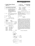
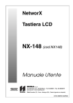
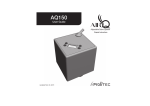
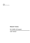
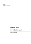
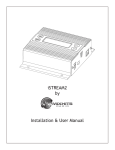
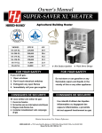
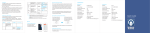
iScent2
by
Nel-Tech Labs, Inc.
Installation & User Manual
Patents Pending
Index:
Introduction ........................................................................................................................3
iScent2 Layout Summary.....................................................................................................4 - 7
LCD Layout Summary ......................................................................................................8
LCD Menu Descriptions.................................................................................................. 9 - 10
Web Summary .......................................................................................................................
11
Installation ...................................................................................................................... 12 - 15
Programming & Operation....................................................................................................
16
Connectivity Test ............................................................................................................. 17
LCD & LAN Status Messages .......................................................................................... 18
Warranty & FCC .............................................................................................................. 19
Introduction:
The iScent2 is an intelligent easy-to-use scenting system utilizing advanced microprocessor controlled fragrance
oil level, pump & atomizing diffuser technology. This system can be used in a wide range of applications from
retail point-of-purchase displays to entice a product purchase to patient waiting rooms to calm occupants.
Unpacking and Inspection:
Before you begin installation, unpack and verify you have all the correct parts.
(1) iScent2
(1) Starter bottle of fragrance oil (This may come in a separate package)
(2) 18" of tubing to extend/direct nebulized output.
(1) 15VDC @ 1.67A power supply
(1) Accessory Kit - Includes four wall mount screws and rubber feet
(1) Instruction manual
Optional Items:
(1) Ethernet cable (if equipped with LAN option)
(1) 2.4GHz Antenna (if equipped with WIRELESS option)
If you are missing any of these parts STOP and call your dealer.
3
iScent2 Layout Summary:
Front of Unit
1
5
2
6
3
4
7
1. NEBULIZER OUT NOZZLE - Nebulized scent is output from this nozzle and can be extended up to
18" with the included tubing. Any connection to the nozzle is NOT TO EXCEED 18"!
2. MEMBRANE KEYPAD - Used to locally program iScent2.
3. DOOR - Used to access 500mL scenting bottle.
4. GRADUATED CLEAR WINDOW - Used to visually check backlit 500mL scenting bottle.
5. 2 x 16 LCD DISPLAY - Displays unit information
6. WIRELESS ANTENNA (optional) - Used to connect iScent2 to a 802.11a/b wireless network.
7. BARREL LOCK - Used to lock door.
4
Side of Unit
1
2.4GHZ
ANT
LAN
2
OFF
(0)
ON
(1)
4
5
6
FAN
OUTPUT
15VDC
1.67A
POWER
SENSOR
INPUT
3
1. LAN - This optional RJ-45 jack is used to connect the unit to a wired LAN.
2. 2.4GHZ ANT - This RP-SMA screw jack is used to attach the optional high-gain WiFi antenna.
3. SENSOR INPUT - This 2-pin modular jack is used to connect to the Pressure Sensor option (#ISCENT2PS).
This option is used when connecting the iScent2 to a HVAC system. When this sensor is activated, only
nebulized scent will be dispensed when the units schedule calls for scenting AND the pressure sensor is
triggered when the HVAC’s fan is running.
4. POWER - Switch to turn the power ON or OFF.
5. 15VDC @ 1.67A - Jack is used for the connection of the supplied AC to DC power supply.
6. FAN OUTPUT - This 2.5mm jack is used for connection of the Modular Fan option (#ISCENT2FAN). This
option is used to direct nebulized scent in a specific direction.
5
Side of Unit (Interior View)
1
2
This is a side view with parts removed to show the nebulizer & bottle detail.
1. NEBULIZER - Nebulizer assembly where 500mL scenting bottle is attached.
2. BOTTLE - 500mL bottle containing scenting oil.
6
Front of Unit (Door Removed View)
1
1
1
1
This is a front view of the unit with parts removed to show the wall mounting holes.
1. WALL MOUNT HOLES - Holes used to wall mount iScent2.
7
LCD Menu
8
iScent2 07.33.D3
Oil Level 100%
(MENU push)
New/Edit
UP=Yes / DOWN=No
(MENU push)
Activate?
UP=Yes / DOWN=No
(MENU push)
Press UP Arrow
to(MENU
Callback
push)
Date and Time
01/01/14 - 12:00
(MENU push)
WiFi Status
OFF
(MENU push)
IP Mode
DHCP
(MENU push)
IP
XXX.XXX.XXX.XXX
(MENU push)
Subnet
XXX.XXX.XXX.XXX
(MENU push)
Gateway
XXX.XXX.XXX.XXX
(MENU push)
Connect-Back #1
XXX.XXX.XXX.XXX
(MENU push)
CB Port #1
XXXX
(MENU push)
Connect-Back #2
XXX.XXX.XXX.XXX
(MENU push)
CB Port #2
XXXX
(MENU push)
Format Unit
And Reboot
(MENU push)
Firmware Version
vXX.XX.X
(MENU push)
Backlight is Off
UP=On / DOWN=Off
(MENU push)
Sensor is Off
UP=On / DOWN = Off
(MENU push)
* CALIBRATION *
* Press UP to Cal *
(MENU push)
MAC Address
XX:XX:XX:XX:XX:XX
(MENU push)
Serial Number
KXXXXXXX
Select Schedule
1
Set Day
All
Set Start Time
00:00 AM
Set Stop Time
11:59 PM
Set On Interval
60s
Set Off Interval
60s
Save Schedule
UP=Yes / DOWN=No
(MENU push)
(MENU push)
(MENU push)
(MENU push)
(MENU push)
(MENU push)
Scent Schedule
EEEEEEEEEEEEEEEE
Scent Schedule
*EEEEEEEEEEEEEEE
Other Changes?
UP=Yes / DOWN=No
All
Monday
Tuesday
Wednesday
Thursday
Friday
Saturday
Sunday
Mon - Fri
Sat - Sun
Schedule
Saved
Schedule
Not Saved
(MENU push)
(MENU push)
(A)ctivate
(D)eactivate
Delete
Do Nothing
LCD Menu (Continued)
To add a new schedule:
1. MENU to the New/Edit screen.
2. Press the UP arrow.
3. Select Schedule number by:
a. Press the UP or DOWN arrow to choose the slot.
b. Press SELECT to set the slot.
4. Set Start Time schedule by:
a. Press the UP or DOWN arrow to choose the hour.
b. Press SELECT to set the hour.
c. Press the UP or DOWN arrow to choose the minutes.
d. Press SELECT to set the minutes.
e. Press the UP or DOWN to choose AM or PM.
f. Press SELECT to set AM or PM.
5. Set Stop Time schedule by:
a. Press the UP or DOWN arrow to choose the hour.
b. Press SELECT to set the hour.
c. Press the UP or DOWN arrow to choose the minutes.
d. Press SELECT to set the minutes.
e. Press the UP or DOWN to choose AM or PM.
f. Press SELECT to set AM or PM.
6. Set ON Interval in seconds by pressing the UP or DOWN arrows, then pressing SELECT.
7. Set OFF Interval in seconds by pressing the UP or DOWN arrows, then pressing SELECT.
8. To Save Schedule press the UP arrow or DOWN to cancel.
To Activate, Deactivate or Delete a scheduled slot:
1. MENU to the Activate? screen.
2. Press the UP arrow.
3. Once in the Scent Schedule menu press the UP or DOWN arrow to choose slot to be changed.
4. An asterisk “*” will signify the slot that is currently chosen.
5. When the correct slot has been chosen then press SELECT.
6. Press UP or Down to choose the following actions:
a. (A)ctivate - This activates the slot you have programmed in the scheduler.
b. (D)eactivate - This deactivates a slot that might be used at a later time.
c. Delete - This deletes the slot and changes status to “E”.
d. Do Nothing - Returns to the previous menu.
Note: User will not be able to Activate a schedule with a zero Interval.
Error will show on the LCD - “ Can’t Activate, Zero in Schedule”.
To Set Date and Time:
1. MENU to the Date and Time menu.
2. Press SELECT to edit .
3. Adjust the date or time using the UP or DOWN arrows, pressing SELECT to move to the next field.
Note: If unit is Internet connnected the time and date will automatically be set from the server.
9
LCD Menu (Continued)
To take unit out of WiFi :
1. MENU to the WiFi Status menu.
2. Press the UP or DOWN arrows to change from ON to OFF.
3. Press SELECT.
4. Press UP to confirm setting.
5. Unit will reboot into Wired Mode if confirmed from previous step.
To Set IP Mode:
1. MENU to the IP Mode screen.
2. Press UP or DOWN to choose DHCP to STATIC.
3. Press SELECT to set DHCP or STATIC. Note unit will reboot after this setting.
To change IP, Subnet, Gateway, Connnect-Back & CB Port:
1. MENU to the IP, Subnet or Gateway screen.
2. Press SELECT and the first octet will be able to be edited.
3. Press the UP or DOWN arrows to choose the new octet setting.
4. Press SELECT to move to the next octet group.
5. Once the last octet is chosen, then press SELECT to set the address.
To change the Backlight that creates a glow effect behind the fragrance bottle:
1. MENU to the Backlight screen.
2. Press UP to turn it ON or DOWN to turn it OFF.
(Default Setting is ON)
To change the Sensor input (if equipped) for HVAC installations to verify FAN is running:
1. MENU to the Sensor screen.
2. Press UP to turn it ON or DOWN to turn it OFF.
(Default Setting is OFF)
To Calibrate Liquid Level Sensor:
1. MENU to *Calibration* screen.
2. Verify iScent2 does not have any bottle installed and door is closed.
3. Press the UP arrow.
4. When instructed reinsert the bottle.
5. Press the MENU button.
6. Unit will take a few initial liquid level readings and display this on the main menu.
Note: Hold the UP or DOWN arrows for more than 5 seconds
to make settings numbers jump ahead faster.
10
Web Browser (Feature on firmware version 07.33 or higher)
The iScent2 LCD has a built-in password protected web browser that will display the units serial number, firmware
version and MAC address. This browser will also allow the units communication mode, connect-back address and
port to be changed.
When changing Mode either DHCP or STATIC must be typed in the “New Settings” column. When
changing to STATIC mode the IP, Subnet and Gateway must all be entered or the settings will not take
when submitted. The Status will indicate if the settings have been updated to the unit.
11
Installation:
Step 1: Wall or shelf mount the unit. Rubber feet and screws are supplied in the accessory kit. Wall mount hole
locations are shown on “Front of Unit (Door Removed View)” drawing on page 7 of manual.
Step 2: Verify the power switch on the right side of the unit is set to OFF. Attach the included power pack to a
wall or power strip receptacle, then attach the other end to the jack on the right side of the unit labeled 12VDC.
Step 3: If using the optional LAN or Wireless see additional detailed instructions in this manual.
Step 4: If using the optional Fan or Pressure Sensor see additional detailed instructions in this manual.
Step 5: If this is the first time using the unit then a liquid level calibration must be done (see Page 10).
Attach the 500mL bottle of scenting oil to the bottom of the nebulizer assembly in the following manner:
a. Unlock and open door.
b. Carefully tilt the bottle enough to fit in the door and feed the nebulizer tube inside the bottle.
c. Screw bottle in a counter-clockwise motion to bottom of nebulizer until snug.
d. Close and lock the door.
Nebulizer
Tube
Step 6: Slide the power switch on the right side of the unit to ON and iScent2 will perform boot sequence.
Step 7: After boot unit will be ready for programming - see “iScent2 Programming & Operation” on page 16 of
manual.
12
Installation - Optional Modular Fan Add-On (ISCENT2FAN) :
Step 1: Attach Fan Add-On Module to nebulizer output barb and turn to desired direction.
Step 2: Connect 2.5mm plug to 2.5mm FAN OUTPUT jack on right side of unit.
13
Installation - Optional Pressure Sensor Add-On (ISCENT2PS) :
Step 1: Attach pressure sensor switch to the plenum of HVAC system.
Step 2: Always follow the individual instructions that come with the sensor for proper installation.
Step 3: Verify power on the iScent2 unit is OFF.
Step 4: Attach the pre wired connector from the Pressure Switch to the SENSOR INPUT on the iScent2.
Step 5: Turn the power on the iScent2 unit to the ON position and let unit boot.
Step 6: Using the menu tree on page 8 go to the “Sensor” menu and press UP to turn sensor input ON.
Tube to HVAC duct
Example of one type of many different possible sensors installations.
14
Installation - Optional LAN or Wireless Option:
Hardwired LAN (Default) - If connected to the Hardwired LAN set the local networks type of IP - either DHCP
or STATIC. If using DHCP everything should set automatically. If using STATIC then use one of these three
methods:
Method 1. The LCD display and keypad (see page 8 - 10).
Method 2. The built in web browser (see page 11 for web portal screen shot).
a. Type the IP of the unit in either IE or Firefox.
b. Type the default password - TLKDIG.
c. Check off STATIC.
d. Enter in IP, Subnet & Gateway.
e. Set DNS and Connect-Back information if required.
f. Click the “Submit” button.
g. Unit will reboot and new settings will take effect.
Method 3. Dealer set through NTL Studio. Call your dealer for details.
Wireless LAN - If connected to the Wireless LAN the only secure method is to use the built-in web portal using
the following steps (see page 11 for web portal screen shot):
Step 1: Type the IP of the unit in either IE or Firefox.
Step 2: Type the default password - TLKDIG
Step 3: Check off “Use 802.11 WiFi Network Port”
Step 4: Enter in WiFi Network Name.
Step 5: Enter in WiFi Network Password with the type of security encryption method.
Example 1: Password is apple and the security is WEP then enter your password as: apple,WEP64
Example 2: Password is TesT1234 and security is WPA then enter your password as: TesT1234,WPA
Example 3: On an unsecured network enter your password as: NONE
Note: After the comma on the encryption type (WEP, WPA or WPA2) there is no space!
Step 6: Set to DHCP or STATIC network. If STATIC then set IP, Gateway and Subnet.
Step 7: Set DNS and Connect-Back information if required.
Step 8: Click the “Submit” button.
Step 9: Unit will reboot into Wireless Mode.
Note: Distance on the Wireless Mode is about 125ft. line-of-sight.
Walls, furniture and other items can reduce this distance.
Note: See Page 10 for taking unit out of WiFi Mode after it has been set on the unit.
15
Programming:
Step 1: Set units date and time (see page 9).
Step 2: If using the LAN or wireless option check connectivity to the Internet (see page 17).
Step 3: If this is first time using the unit then calibrate the liquid level sensor (see page 10).
Step 4: Verify bottle is installed (see page 12).
Step 5: Program a schedule slot (see page 9).
Step 6: Activate schedule slot (see page 9).
Step 7: Return to main menu.
Operational Flowchart:
Unit is IDLE
NO
Is Schedule Active?
NO
YES
Is Schedule Calling
For Scenting Action
YES
Wait for 60s
Is SENSOR INPUT
Activated?
YES
NO
Is HVAC fan ON?
NO
YES
Scent for
“SCENT ON INTERVAL”
& Turn ON
FAN OUTPUT
Scent for
“SCENT OFF INTERVAL”
& Turn OFF
FAN OUTPUT
Important Note: Most of the units functions including feedback of oil liquid levels can be remotely
operated and monitored by special software. See your dealer for more details.
16
Connectivity Test:
Step 1: Verify the power switch on the right side of the unit is set to ON.
Step 2: On the LCD menu verify unit has a valid IP, subnet and gateway.
IP
010.001.001.206
Example:
Subnet
255.255.255.128
Gateway
010.001.001.120
Step 3: On the LCD menu go to “ Press UP Arrow To Callback ” and press the UP ARROW.
Press UP Arrow
To Callback
Step 4: The LCD will display “ Forcing Connect Please Wait ”
Forcing Connect
Please Wait
Step 5: If there is a Connect-Back record waiting for the unit then the LCD will display “ ACTIVE CONNECT
XXX.XXX.XXX.XXX ”.
Example:
ACTIVE CONNECT
10.1.1.171
If there is no record waiting then it will display “ CONNECTING TO XXX.XXX.XXX.XXX
moments on the LCD to confirm a successful connectivity.
Example:
” for a few
CONNECTING TO
10.1.1.171
17
Other LCD Status Messages:
Unit is booting:
BOOTING...
PLEASE WAIT...
Unit is initializing:
SYSTEM IS
INITIALIZING...
Unit is getting ip address:
iScent2
SEEKING IP
Dealer is connected to unit:
DIRECT CONNECT
IS ACTIVE
Unit is connected to dealer:
ACTIVE CONNECT
XXX.XXX.XXX.XXX
Format and reboot in progress :
FACTORY RESET
In PROCESS
Unit is formatting:
System is
Formatting
Unit is changing IP Modes:
SAVING CHANGES
UNIT WILL REBOOT
Unit cannot find a valid IP:
Connect-Back IPs
Not Valid
LAN LED Indicators
MADE IN
THE USA
LAN
CHANNEL B
CHANNEL A
IN
OUT
600Ω
8Ω
IN
OUT
600Ω
8Ω
POWER
OFF
Action
10MB
Not Used
100MB
18
LED
OFF
FLASHING
SOLID
Action
No Activity
Activity
Link
LED
OFF
FLASHING
SOLID
ON
Limited Warranty
TERMS: Nel-Tech Labs warrants to the original purchaser (“Buyer”) that the Product sold is free from defects in material and
workmanship at the time of purchase. The warranty period begins at the time of Product’s original purchase by the first end-user. The
warranty applies for five (5) years from the original date of purchase, or as long as the product is owned by the original purchaser,
whichever comes first. Included in the warranty are parts and labor. Buyer must provide written notice to Nel-Tech Labs of any defective
part or conditions within the warranty period. If the defect is not the result of improper use, service, maintenance or installation,
and if the equipment has not been otherwise damaged or modified after shipment, Nel-Tech Labs or its authorized representative
shall either replace or repair the defective Product at Nel-Tech Labs’s option. No credit shall be allowed for work performed by
Buyer or unauthorized parties. Out-of-warranty repairs are invoiced at the current Nel-Tech Labs hourly rate plus the cost of parts,
shipping and handling. In the event that the product serial number is missing or has been tampered with in any way, the foregoing
warranty is void and without effect and Nel-Tech Labs shall have no liability whatsoever on account of defects to such product.
CONSUMABLES: The iScent2 is designed to work with specific fragrance oils that meet stringent guidelines both in usability and
safety. Use of any oil other than what is supplied by Nel-Tech Labs, Inc. or its exclusive oil suppliers will void the warranty.
LIMITATIONS: Except as stated above, there are no warranties, express or implied, that extend beyond the specifications for the
product. Nel-Tech Labs expressly disclaims any warranty, express or implied, that equipment sold hereunder is of merchantable
quality or that it can be used, or is fit for any particular purpose. Buyer purchases and accepts equipment solely on the basis of the
warranty here in above expressed. Under no circumstances shall Nel-Tech Labs be liable by virtue of this warranty or otherwise
for any special indirect, secondary or consequential damages to any person or property arising out of the use or inability to use the
product.
REPAIRING OR REPLACING PRODUCT: Buyer may obtain the repair or replacement of any eligible part or equipment covered
under this warranty through a Nel-Tech Labs dealer only. Buyer is responsible for all shipping and handling charges in connection
with the performance of this warranty. Products returned to Nel-Tech Labs must be securely packaged to prevent damage in transit,
freight prepaid, and insured for replacement value. A return authorization number assigned by Nel-Tech Labs must be clearly marked
on the outside of the shipping container. Proof of purchase must accompany shipment. Items delivered to Nel-Tech Labs without a
return authorization clearly marked on the outside of the shipping container, and/or without proof of purchase is refused.
CONTACT: Please contact Nel-Tech Labs at the address and phone number below to receive a return authorization number and to
arrange for the repair or replacement of a flawed part covered by this warranty. Please indicate the Product’s serial number in all
correspondence or a RMA authorization number in the absence of a serial number. Nel-Tech Labs, 4 Ash Street Extension, Derry,
NH 03038, Phone: 1.603.425.1096.
COPYRIGHT NOTICE: Unauthorized or unlicensed use of copyrighted audio content is illegal and Nel-Tech Labs, Inc. takes no
responsibility for such action by the user of this equipment.
FCC Part 15 : This equipment has been tested and found to comply within the limits for a Class A digital device, pursuant to Part
15 of the FCC rules. These limits are designed to provide reasonable protection against harmful interference when the equipment is
operated in a commercial environment. This equipment generates, uses and can radiate radio frequency energy and, if not installed
and used in accordance with the instruction manual, may cause harmful interference to radio communications. Operation of the
equipment in a residential area is likely to cause harmful interference in which case the user will be required to correct interference at
his own expense. In order to maintain compliance with FCC regulations shielded cables must be used with this equipment. Operation
with non-approved equipment or unshielded cables is likely to result in interference to radio & television reception.
Changes or modifications not expressly approved by Nel-Tech Labs could void the users’ authority to operate the equipment.
IC ES 003 : This Class A digital apparatus complies with Canadian ICES-003 C et appareil numérique de la classe A est conform e
à la norme NMB-003 du Canada.
CE CONFORMITY : The Nel-Tech Labs iScent conforms with the following standards, in accordance with the EU Safety, EMC
Emissions, & EMC Immunities : EN 60950-1:2001, EN 55022:1998 for Class A, EN 55024:1998 + A1:2001 + A2:2003, EN 610004-2:1995 + A1:1998, EN 61000-4-3:1995, EN 61000-4-4:1995, EN 61000-4-5:1995, EN 61000-4-6:1996, EN 61000-5-11:1994.
19
Nel-Tech Labs, Inc.
4 Ash Street Extension
Derry, NH 03038
1.800.344.4685
nel-techlabs.com
iscent2_manual
Rev. D - 06/15
Copyright © 1984 - 2015 by Nel-Tech Labs, Inc.
Patents Pending