1
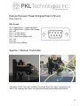
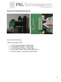
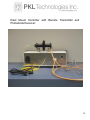
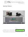
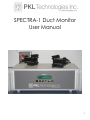
SPECTRA-1 Duct Monitor
User Manual
1
About This Manual
Document Purpose and Intended Audience
This document provides the user of Spectra-1 Duct Monitor gas analyzer with
instructions for setting up and performing real-time measurements of select gases.
Document Summary
Chapter
Description
Chapter 1: User Information/Warranty
Contains descriptive information about
Spectra-1 Duct Monitor laser based
gas detection instrument.
Warranty description.
Chapter 2: Set-up and operation
Provides set-up and installation
instructions. System configuration and
user settings overview.
Chapter 3: Troubleshooting
Contains recommended steps to
isolate and correct common problems.
Chapter 4: Specifications
Contains technical specifications.
2
Chapter 1
User Information
Caution – use of controls or adjustments or performance of procedures other than
those specified herein may result in hazardous radiation exposure.
Class 1 Laser Product
Spectra-1 contains no user serviceable components. All service work to be performed
by PKL Technologies Inc. personnel only. Return Spectra-1 to PKL Technologies Inc.
for any service or repair work. Spectra-1 is not to be opened or modified in any way –
broken seal will void warranty.
Do not operate Spectra-1 if the unit is not complete.
No scheduled maintenance required for continued Class 1 compliance.
Please refer to Chapter 2 for proper instrument set up and operation – failure to do so
may cause instrument damage or inaccurate data reported.
This Laser Product is designated as Class 1 during all procedures of operation.
Spectra-1 Serial Number:
Wavelength:
nm
Laser Power for classification:
<10 mW
Beam Diameter:
<20mm at aperture
Divergence:
>1.5 mrad
Transverse Beam Mode:
TEM00
Emissions:
Continuous Wave
Tested By:
Test date:
3
Warranty
PKL Technologies Inc. hereby represents and warrants all Products manufactured by
PKL Technologies Inc. to be free from defects in workmanship or material during a
period of twelve (12) months from the date of delivery. If any Product proves however to
be defective in workmanship or material within the period herein provided PKL
Technologies Inc. undertakes to the exclusion of any other remedy to repair or at its
own option replace the defective Product or part thereof free of charge and otherwise on
the same conditions as for the original Product or part without extension to original
warranty time. Defective parts replaced in accordance with this clause shall be placed at
the disposal of PKL Technologies Inc.
PKL Technologies Inc. also warrants the quality of all repair and service works
performed by its employees to products sold by it. In case the repair or service works
should appear inadequate or faulty and should this cause malfunction or non-function of
the product to which the service was performed PKL Technologies Inc. shall at its free
option either repair or have repaired or replace the product in question. The working
hours used by employees of PKL Technologies Inc. for such repair or replacement shall
be free of charge to the client. This service warranty shall be valid for a period of six (6)
months from the date the service measures were completed.
The warranty is however subject to the following conditions:
a) A substantiated written claim as to any alleged defects shall have been received by
PKL Technologies Inc. within thirty (30) days after the defect or fault became known.
This warranty does not however apply when the defect has been caused through:
a) Normal wear and tear or accident.
b) Misuse or other unsuitable or unauthorized use of the Product or negligence or error
in storing, maintaining or in handling the Product or any equipment thereof.
c) Wrong installation or assembly or failure to service the Product or otherwise follow
PKL Technologies Inc. service instructions including any repairs or installation or
assembly or service made by unauthorized personnel not approved by PKL
Technologies Inc. or replacements with parts not manufactured or supplied by PKL
Technologies Inc.
d) Modifications or changes of the Product as well as adding to it without PKL
Technologies Inc. prior authorization.
e) Other factors depending on the Customer or a third party.
Notwithstanding the aforesaid PKL Technologies Inc. liability under this clause shall not
apply to any defects arising out of materials, designs or instructions provided by the
Customer.
This warranty is expressly in lieu of and excludes all other conditions, warranties and
liabilities, express or implied, whether under law, statute or otherwise.
4
Chapter 2
Set-up and Operation
Selecting Location
Spectra-1 is an open-path gas sensing instrument. A clear line of sight between the
Spectra-1 remote transmitter and the remote photodiode receiver is required. Typical
stack/duct applications provide for openings on opposite sides of the stack/duct. Where
flanges are used ensure parallelism of opposing flange faces. The Spectra-1 remote
transmitter is mounted on one side of the stack/duct, and the remote photodiode
receiver is mounted on the opposite side of the stack/duct. Purge gas connections may
be required – Nitrogen is typically used. Purge gas pressure should be set just above
stack/duct pressure.
Remote Transmitter and Receiver Positioning
Spectra-1 remote transceivers are placed on an adapter flange with an adjustable
mount. The adjustable mount is used to aim the Spectra-1 remote transceiver through
the stack/duct onto the retro-reflector on the opposing side of the stack/duct.
Adjustments will be required to adjust to the remote transceiver to provide the desired
signal level. This will be done after Spectra-1 is powered up.
An infrared sensor card is very useful for initial alignment through stack/duct.
A fiber coupled single mode visible laser source is also useful for alignment through the
stack/duct.
The Spectra-1 remote transceivers are preconfigured for specified stack diameters and
dust loading for optimal signal level.
5
Spectra-1 Control Unit
2 X 20 character LCD display:
● gas concentration
● ppm or ppm-m
● distance (optical path length)
● signal level bar graph
● signal level % reading
● configuration/menu display
Keypad for system configuration:
● distance (stack or duct diameter – optical path length)
● gas concentration - ppm or ppm-m
● averaging time .5 to 60 seconds
● maximum signal level set (i.e. 95%)
● minimum signal level set (i.e. 2%)
● RS232 com port setting (baud rate)
● calibration settings (Factory Set)
● Spectra-1 settings output
● display IP address
6
Spectra-1 Control Unit – rear panel
A
B
C
D
E
F
A.
B.
C.
D.
E.
F.
ON/OFF Switch & 100-240VAC 50/60Hz input (Fuse 5mm X 20mm, 1A 250V)
FC/APC single mode fiber optic output to remote transceiver
Female DB9 power out / signal return to/from remote transceiver (see pin-out)
RJ45 Ethernet socket
Male DB9 RS232 serial data output (see pin-out) (Nul modem cable required)
USB
RS232 Serial Output Pin-out:
[Rear panel E]
DB-9 Male
Pin 1: NC
Pin 2: Rx
Pin 3: Tx
Pin 4: NC
Pin 5: Gnd
Pin 6: NC
Pin 7: NC
Pin 8: NC
Pin 9: NC
7
Remote Receiver Power & Signal Return Pin-out:
[Rear Panel C]
DB-9 Female
Pin 1: Signal Return – (Alpha 6460 Blue)
Pin 2: Signal Return + (Alpha 6460 Orange)
Pin 3: NC
Pin 4: -12 VDC (White)
Pin 5: +12 VDC (Green)
Pin 6: Cable Shield (Alpha 6460)
Pin 7: NC
Pin 8: NC
Pin 9: DC Ground (Black)
Spectra-1 Remote Transmitter
Adjustable FC/APC fiber optic connector for Single Mode fiber cable. Adjustments are
used to aim outgoing laser beam onto opposite mounted remote photodiode receiver.
8
Remote Photodiode Receiver
Remote Photodiode Wiring:
Labeled on photodiode PCB.
1.
2.
3.
4.
5.
– 12 VDC (White) Shielded 18 AWG Cable
DC GND (Black) Shielded 18 AWG Cable
+ 12 VDC (Green) Shielded 18 AWG Cable
Out Gnd Return Signal – (Blue) ALPHA 6460 Cable
Out Return Signal + (Orange) ALPHA 6460 Cable
9
Rack Mount Controller with Remote Transmitter and
Photodiode Receiver:
10
Spectra-1 Start-up
Power switch is turned on. Spectra-1 will display:
PKL TECHNOLOGIES INC
SPECTRA-1 BOOTING
This will be displayed during internal computer boot-up – approximately 2 minutes.
11
After Spectra-1 booting period display reads:
After warm up period display reads:
This takes as long as the data averaging
period setting. (1 second +)
After warm up, display will read no data
available, if not in optical alignment.
Proper optical alignment with the photodiode
receiver will produce the following normal
operational display output.
SPECTRA-1 Warm up
™™™™™
Starting...
HF 250M
No data available
78.35PPM
™™™
HF 250M
LVL 31%
Signal Level (LVL) should fall between 30% and 80% for best operation.
Configuration Menu – Spectra-1 Options
Press CONFIG/MENU key to enter Spectra-1 options.
Use the arrow keys ▲▼ to select the menu item you wish to change. (Scrolling menu)
Press the ENTER/SELECT key to make change. After making a change press the
ENTER/SELECT key. Press the RUN key to return to normal Spectra-1 operation.
>Distance to refl. ↓
PPM or PPMM
<ENTER>
Dist to reflector
250.™ [m] ↕↔
▼
>PPM or PPMM
Set Averaging
↕
Units: PPM or PPMM
PPMM ↕
▼
12
>Set averaging
Max signal level
↕
<ENTER>
Samples to average
004 Seconds ↕↔
▼
>Max signal level
Min signal level
↕
Maximum signal level
95 % ↕
↕
Minimum signal level
3 % ↕
▼
>Min Signal level
Com settings
▼
>Com settings
Logging options
↕
Baud rate
9600 ↕
▼
>Logging options
Data log dump
↕
Logging
Enabled ↕
▼
>Data log dump
Calibration
↕
Dump data to USB
Yes ↕
▼
>Calibration
↕
Spectra-1 settings
Do not change - Factory Calibration!
▼
13
>Spectra-1 settings↕
Laser temperature
<ENTER>
Dump settings
No ↕
▼
>Laser temperature ↕
Display IP address
Laser temperature
32.50 [C] ↕
▼
>Display IP address↕
Periods to average
IP address is
Press any key
▼
>Periods to average↕
Minimum r2 filter
Periods to average
080 sets ↑∆~
▼
>Minimum r2 filter
Data log space
↕
Min r2 value (0=off)
0.0 ↑
▼
>Data log space
↕
Serial data debug
168MB currently
Press any key
▼
>Serial data debug
↑
Dump data to serial
Disabled ↕
14
CONFIG/MENU Items Description:
Distance to refl.
PPM or PPMM
Set averaging
Max signal level
Min signal level
Com settings
Logging options
Data log dump
Calibration
Spectra-1 settings
Laser Temperature
Display IP address
Periods to average
Minimum r2 filter
Data log space
Serial data debug
- Distance between Spectra-1 and the retro-reflector
(or duct optical path length)
- Change from PPM mode to PPM-M mode
- Set Spectra-1 averaging from .5 to 60 seconds
- Maximum signal level setting for data analysis
- Minimum signal level setting for data analysis
- Baud rates: 2400, 9600, 19200, 38400, 57600, 115200, 230400
- Enable or disable internal data logging (168MB allocated)
- Internally logged data transfer to USB memory stick (Optional)
- Do not change factory settings!
- Serial output of internal settings of Spectra-1
- Set laser diode temperature set point (future development)
- Display IP address when connected to Ethernet
- Internal sampling rate – Do not adjust!
- Filter to display data with a minimum r2 value
- Internal data logging memory remaining
- Serial data debug data string output via serial port(leave disabled)
Serial Data Output/Logging Format:
2007-03-12
2007-03-12
2007-03-12
2007-03-12
2007-03-12
11:37:14
11:37:18
11:37:22
11:37:26
11:37:30
MDT,0x00000001,NH3,0.46,0.00,ppmm,21%,5.0,11,0,0,0
MDT,0x00000001,NH3,0.38,0.00,ppmm,21%,5.0,12,0,0,0
MDT,0x00000001,NH3,0.41,0.00,ppmm,21%,5.0,11,0,0,0
MDT,0x00000001,NH3,0.31,0.00,ppmm,21%,5.0,12,0,0,0
MDT,0x00000001,NH3,0.35,0.00,ppmm,21%,5.0,11,0,0,0
Format is : t,s,g,r,p,w,P,T,d,c,e,l,h
t = time with time zone, 24 hour clock
s = status code – see below
g = gas species
r = averaged r-squared value
p = averaged gas concentration
w = ppm-m or ppm units
P = signal level %
d = distance to retro-reflector (meters)
c = number of samples in averaging period
e = number of times we tried to get a sample set but did not
l = number of low signal level samples (also included in e)
h = number of high signal level samples (also included in e)
15
Status codes:
0x00000001 Normal Signal Present
0x00000002 No Signal Present
0x00000004 Low Signal Level
0x00000008 High Signal Level
0x00000010 Unstable Signal Level (Both High and Low Signal Levels)
0x00000020 Log File Full (Less than 10MB Free Space)
16
Serial Port Connection:
Connect serial port cable (DB-9 female-female)
from RS232 output on Spectra-1 to com port
on laptop or desktop computer.
A null modem cable is required.
In the case that there is no DB-9 serial port
available, a USB serial adapter may be used.
Plugable USB Serial Converter works well.
The serial port connection speed is set in the
CONFIG/MENU set-up of Spectra-1. This is
outlined in the Configuration Menu section.
Once connection is established Spectra-1
DataView or HyperTerminal may be used.
Data bits: 8
Parity: none
Stop bits: 1
Flow control: none
Plugable USB serial adapter
Spectra-1 DataView Program for
Data display and logging
17
Chapter 3
Troubleshooting
Common Problems:
●
Mains Power Connection
●
Transceiver Pin-out verification and testing for +12VDC and -12VDC
●
Fiber output power level (using fiber power meter)
●
Serial Port Communication
Check baud rate setting, and correct DB-9 cable connection.
Check com port settings on laptop or desktop computer.
●
Low Signal Level
Check for alignment
Ensure Spectra-1 transmitter and photodiode optical surfaces are clean.
Check for clear obstruction free optical path.
●
High Signal Level
Re-check transmitter alignment.
●
Stable Spectra-1 Transmitter and Receiver Mounting
Ensure Spectra-1 transmitter and photodiode receivers are suitably mounted to
eliminate alignment problems.
●
Please consult with factory for any problems encountered. Your help will provide
for a more extensive and detailed troubleshooting guide.
18
Chapter 4
Specifications
Spectra-1 Dimensions:
Rack Mount Controller:
Power Input: 100-240VAC 50/60Hz input on rear panel
19