1
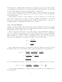
Tutorial on agent-based models
in NetLogo
Instructor: Catherine Beauchemin ([email protected])
Assistant: Laura Liao
Department of Physics, Ryerson University
June 16, 2011
Abstract
This tutorial written in NetLogo will introduce the participant to designing and
implementing an agent-based model. The project will consist of modelling T cell movement within a lymph node. It is broken into a series of incremental steps of increasing
complexity. Each step is described in detail and the code to type in is initially provided. However, the project has room to grow in complexity and biological realism so
participants who finish more rapidly will be assisted in bringing their project beyond
the scope of the tutorial or in developing a project of their own.
Suggested reading
In preparation for the class and tutorial, participants are encouraged to read:
• N Moreira. In pixels and in health: Computer modeling pushes the threshold of medical
research. Science News, 169(3):40–44, 21 Jan, 2006.
• C Beauchemin, J Samuel, J Tuszynski. A simple cellular automaton model for influenza
A viral infections. J. Theor. Biol., 232(2):223–234, 21 Jan, 2005.
doi:10.1016/j.jtbi.2004.08.001.
• DM Catron, AA Itano, KA Pape, DL Mueller, and MK Jenkins. Visualizing the first
50 hr of the primary immune response to a soluble antigen. Immunity, 21(3):341–347,
Sep, 2004. doi:10.1016/j.immuni.2004.08.007.
1
1.1
NetLogo: A basic introduction
Getting NetLogo
To obtain NetLogo for your computer operating system (Mac, Linux, Windows), visit the
NetLogo website at http://ccl.northwestern.edu/netlogo.
1
1.2
Looking at a finished model from the Models Library
We’ll now have a look at what an example finished client looks like.
1. Select “File” → “Models Library”
2. Select “Sample Models” → “Biology” → “Tumor”
You see 3 tabs:
Interface: Where the simulation gets displayed and the end-user can interact with it using
the available sliders, buttons, etc. which were made available by the author of the
model.
Information: Where you can find general information about the model: what it is, how to
use it, etc. It is essentially the help page for the model.
Procedure: Where the NetLogo code driving the model is located. You can modify it and
see what happens or you can write brand new code.
1.2.1
Exploring the Interface tab
The “setup” button is a standard button in NetLogo and it is used to initialize the model,
i.e., set up the starting conditions for your model. For example, how many cells do you want
initially, where should they be, what colour should they be, what should be their initial state
(e.g., infected, uninfected, dead).
The “go” button does exactly what you’d expect: it makes the simulation go. But be
sure to press “setup” before you press go.
The remaining buttons allow you to trigger certain actions during the course of the
simulations. The various sliders and switches allow you to adjust various parameters or
conditions of the simulations: You can play around with them even as the simulation is
running. Finally, the monitors and plots are used to display variables of the simulations
(e.g., how many cells there are).
Note that if you want to restart the simulation, you can press “go” to stop the currently
running simulation and then press “setup” to reinitialize it.
Now that you know how to run a model, let’s learn how to make one.
1.3
Some NetLogo basics
The NetLogo User Manual is available at http://ccl.northwestern.edu/netlogo/docs/.
Here, I will provide a quick intro to help you get started.
A NetLogo simulation consists of a world made up of rectangles (in 2D) or blocks (in 3D)
called “patches” within which mobile agents called “turtles” can move and evolve based on
the turtles and patches around them and those encountered along their path. The patches
can also evolve; more on that later.
There are 3 types of agents of importance for us in NetLogo:
2
Patch: A small rectangle (in 2D) or block (in 3D) of the simulation world. A patch is
identified by its coordinate, (x, y) or (x, y, z). Thus it CANNOT move but it can hold
variables (e.g., its colour, how long ago it was visited, what type of a site it is). You
cannot have different breeds of patches: there is only one set of patches making up
your world.
Turtle: A mobile agent which can go from one patch to another based on whatever rules
are defined for its motion. Because it can move, a turtle agent is identified not by its
coordinate but instead by a “who” number. Turtles can also hold variables, and you
can have different breeds of turtles (different types of turtle agents, e.g., rabbits and
hares).
Link: A connection which can be created between two turtle agents. It appears as a line
corresponding to the shortest path between the two turtles. A link is identified by the
who number of the two turtles it links. Links can hold variables, and you can have
different breeds of links.
Note that by default the NetLogo world uses toroidal boundary conditions meaning that
anything which disappears off one edge of the world reappears on the opposite side. You
can change this (in NetLogo 2D only) under “Settings...” by unchecking the “World wraps”
checkboxes. For our two projects, we’ll use the default periodic boundary conditions.
2
2.1
Project: T cell movement within lymph nodes
Project description
This project consists of T cells moving around within a 3D lymph node, encountering antigenloaded dendritic cells (DCs) and making brief contacts. You will first create 100 T cells and
have them move around randomly. You’ll then introduce 2 DCs and when a T cell encounters
a DC, the T cell will stop moving for 3 min before resuming its regular motion. You will keep
track of how many T cells have encountered a DC and you’ll plot how that number evolves
over time. You will also plot the tracks of some T cells, much like what gets recorded during
two-photon microscopy experiments. Some extensions of this project include: making each
DC bear different antigens and tracking how many cells have encountered each DC and how
many have encountered both, tracking how the number of contacts changes for different T
cell movement models.
2.2
2.2.1
Step-by-step instructions
Creating our set of T cells and DCs
This project is in 3D so you will need to use Netlogo 3D. Since our T cells and DCs will
be moving around, they will be turtles. To make things clearer, we’ll create two breeds of
turtles: T cells and DCs. At the very top of your ‘Procedure’ tab, you should enter:
3
breed [tcells tcell]
breed [DCs DC]
; the T cells
; the dendritic cells (DCs)
When creating a new breed, the first word is the plural name of the breed and the second
is its singular name. For example, if we were creating a breed of mice, we’d probably want
breed [mice mouse]. Note that ; is used to indicate a comment: everything after the ; is
ignored by NetLogo.
We’ll create the T cells and DCs as circles which map to spheres in NetLogo 3D. We’ll
make the DCs twice as large as the T cells. We’ll make 100 green T cells and 2 red DCs. So
let’s write the ‘setup’ function to do this:
to setup
clear-all
set-default-shape turtles "circle" ; all turtles will be circles (spheres)
create-tcells 100 [
set color green
; make T cell green
setxyz random-xcor random-ycor random-zcor ; put T cell at random location
]
create-DCs 2 [
set size 2
; make DC of size 2 (twice that of T cells)
set color red
; make DC red
setxyz random-xcor random-ycor random-zcor
]
end
Let’s link the ‘setup’ function to a ‘setup’ button. Go to your ‘Interface’ tab. Make
sure ‘Button’ is selected, press ‘Add’, and click anywhere in the Interface window. Under
‘Commands’ type ‘setup’, i.e. the name of the function you just created. Every time you
click the ‘setup’ button, your ‘setup’ function is run. Click it a few times to see how your
initial setup changes.
2.2.2
Setting the T cells in motion
We’d like to make our T cells move. To begin with, let’s make them move randomly, but with
a preference for continuing in their current direction (i.e. no drastic turn-arounds). We’ll
create a ‘go’ function just below our ‘setup’ function in our Procedure tab:
to go
ask tcells [
right random-normal 0 90 ; Pick random turn angle: avg = 0 std dev = 90 deg
roll-right random-normal 0 90 ; Pick random roll angle
forward 1
]
end
4
The ‘right angle’ command turns your turtle to the right by angle degrees. Here, instead
of specifying the exact angle, we use ‘random-normal 0 90’ which will pick a random angle
from a normal distribution of mean zero and standard deviation 90◦ .
Now, create a button as before, but this time enter ‘go’ in the ‘Command’ and check the
‘Forever’ checkbox. Click the button: wow, look at these T cells go! You can adjust the
speed with the slider.
But perhaps you’d like to create a button to see the T cells move by one step only.
Sure, create a button as before, enter ‘go’ in the ‘Command’, but this time, do not check
the ‘Forever’ checkbox and you might want to change the display name to ‘one step’ or
something similar to distinguish it from the other ‘go’ button.
2.2.3
Let’s get Physical
Alright, we have nice little balls moving around a grid, travelling at a speed of one patch
per time step. What is that?! We need to map the time and space in our model to REAL
physical time and space. Here is how to do this.
Since we did not specify the size of our tcells, NetLogo created them with a diameter of
one (1). So without even noticing, we have decided that a distance of 1 in our simulation
space corresponds to a physical distance of 8 µm in real life, i.e. the diameter of a T cell.
This seems like a good choice so we’ll leave it like that. As for time, let’s decide that each
time step of our simulation corresponds to 0.5 min (or 30 s). So let’s define
0.5 min
1 time step
8 µm
ds =
1 patch
dt =
Based on the two-photon microscopy literature, we know T cells move at a speed of about
16 µm/min. How do we convert that to units of patch per time step for use in NetLogo?
16 µm
0.5 min
1 patch
vNetLogo =
×
×
1 min
1 time step
8 µm
8 µm
1 patch
=
×
1 time step
8 µm
1 patch
=
1 time step
So, more generally, if you want to convert your real speed to a NetLogo speed, you’d write:
vNetLogo = vreal life ×
real time
1 patch
dt
×
= vreal life ×
1 time step real space
ds
So let’s adjust our simulation accordingly. At the top of our file, above all functions, add
the following line
5
globals [ dt ds tcell-step ]
; dt = duration of one step in min/time step
; ds = size of one patch in um/patch
; tcell-step = size of tcell step in patches/time step
in ‘to setup’ add
set dt 0.5 ; 0.5 min per time step
set ds 8
; 8 um per patch
set tcell-step 16 / ds * dt ; (16 um/min)*(1 patch/8 um)*(0.5 min/time step)
and modify your ‘to go’ to be
to go
ask tcells [
right random-normal 0 90
roll-right random-normal 0 90
forward tcell-step
]
tick-advance dt
end
Now your tick counter in the 3D View is in minutes. Let’s adjust its label accordingly.
Click on ‘Settings’ and under ‘Tick counter label’ enter ‘Time (min)’, and hit ‘Ok’. I also
recommend you set the update to ‘on ticks’ rather than ‘continuous’.
2.2.4
Designing T cell-DC contacts
Two-photon microscopy has taught us that when a T cell encounters a DC, it will pause
for about 3 min before resuming its regular motion. We also know that DCs have dendrites
approximately 19 µm [3]. Therefore, we can design T cell-DC contact by imposing the
following two rules:
• A T cell is considered in contact with a DC if it is within a radius of 19 µm of the DC.
Note that for us, this corresponds to a distance of 2 patches (19 µm × 1 patch/(8 µm)).
• A T cell stops moving for 3 min once it is in contact with a DC.
For this purpose it might make sense to use links. We will create a link between a T cell and
a DC when the distance requirement is met, and we could give the link a property tDCfree
which would keep track of the time left before the T cell is free from the DC.
At the top of the file, before the functions, add
links-own [ tDCfree ]
6
This states that all links will now have a variable called tDCfree. It is like globals
variables, but it belongs only to a specific type of agent, in this case the link agents. Next,
we’ll break the to go function into several functions to make the code clearer. In your code,
replace the to go function with
to go
move-tcells ; move T cell movement commands into a function
identify-DCbound-tcells ; new function to identify DC-bound T cells
update-link-status
; new function to update DC-T cell links
tick-advance dt
end
to move-tcells ; function for T cell motion
ask tcells [
right random-normal 0 90
roll-right random-normal 0 90
forward tcell-step
]
end
to identify-DCbound-tcells ; function to identify DC-bound T cells
end
to update-link-status ; function to update the DC-T cell links
end
Here, we’ve left the definition of the two new functions to later. It’s good to make your
changes incrementally. Now check that your code still works as before by pressing the ‘setup’
and ‘go’ buttons. If all is still working, you’re ready to start creating the identify-DCbound-tcells
function. What we want is to:
• Create a directed link from the DC and all T cells within a 2 patch diameter.
• Make the link red, just like the DC.
• Set the tDCfree to 3 min
• Make the linked T cells blue
Here is how you do this in NetLogo
to identify-DCbound-tcells ; function to identify DC-bound T cells
ask DCs [
create-links-to tcells with [ color != blue ] in-radius 2 [
set color red ; make the link red
7
set tDCfree 3 ; bound for 3 minutes
ask end2 [ set color blue ] ; make the linked T cell blue
]
]
end
For each DC, create-links-to creates a link from that DC to all T cells whose colour is not
blue which are located within a radius of 2 patches. The with [color != blue] ensures
that only T cells that are not blue (i.e. that are not already linked to a DC) are considered.
The ask end2 [...] means ask the turtle at the end of the link (in this case it is a T cell
since the directed link is from the DC to the T cell) to become blue.
That’s great, but now the T cells remain blue forever and their link to the DCs are never
removed. Time to write our update-link-status function:
to update-link-status ; function to update the DC-T cell links
ask links [
set tDCfree tDCfree - dt ; update time remaining for link
if tDCfree < 0 [ ; if tDCfree has elapsed
ask end2 [ set color green ] ; set T cell to its green colour
die ; kill the link (delete it)
]
]
end
Wow, this is awesome! But I sure wish we could track of how many encounters took place. . .
2.2.5
Counting the DC-T cell encounters
It would be nice to know how many DC-T cell encounters occured. That’s where a Monitor
comes in handy. First, let’s create a global variable in our Procedure to keep track of DC-T
cell encounters: we’ll call it nDCmeet. So
globals [ dt ds tcell-step nDCmeet ]
; ...
; nDCmeet = number of DC-T cell encounters
and then somewhere within create-links-to in the identify-DCbound-tcells function,
you can add
set nDCmeet nDCmeet + 1
Now, in your ‘Interface’ tab, add a ‘Monitor’. Under ‘Reporter’ enter nDCmeet and under
‘Display name’ something like Number of DC-T cell encounters for clarity. Now run the
simulation and see how the Monitor gets updated and keeps growing as more and more
encounters occur.
8
2.2.6
Plotting the DC-T cell encounters
Ah, yes, a graph would be nice indeed. Here’s how you do this. In your to go function, just
above tick-advance dt add the following line
plotxy ticks nDCmeet
This will plot the number of DC-T cell contacts made thus far (nDCmeet) as a function of
time (ticks).
In your ‘Interface’ tab, add a ‘Plot’, call it something meaningful like Number of DC-T
cell encounters and set appropriate names for the x and y axis labels (e.g., time (min),
and Number). Now run the simulation and see what happens... cool!
2.3
Open-ended problems
Well, that was fun. Now it’s your turn! Below are a few challenging additions for you to
work into your code. If you have time, dive in and see how far you can get.
To assist you in writing the code, the following resources will be invaluable:
NetLogo User Manual You will find it at http://ccl.northwestern.edu/netlogo/docs.
In particular, under Reference, check out the Programming Guide and the NetLogo
Dictionary (from the left-hand side menu).
Models Library You will find those within NetLogo under ‘File’ → ‘Models Library’. In
particular, check out the ‘Code Examples’ models which are very helpful. Most of these
codes are also available online at http://ccl.northwestern.edu/netlogo/models,
but not the ‘Code Examples’, unfortunately. Read the Models’ description to see if it
is likely to contain the type of code/behaviour you are looking to code-up in your own
simulation.
2.3.1
A 2-antigen system
This extension consists of making each of the 2 DCs bear different antigens and tracking how
many cells have encountered each DC, and how many have encountered both. You could,
for example, assign a different colour to your 2 DCs and have T cells change their colour to
match that of the DC they have encountered, and have each T cell record internally how
many times they have encountered each DC. You could also use colour to visually identify
those T cells which have encountered both.
2.3.2
The effect of T cell movement
This extension consists of exploring how different modes of movement for T cells affect the
number of DC-T cell encounters over the course of the simulation. For inspiration for T cell
movement, check out these references: [1, 2, 4].
9
2.3.3
Random walk versus chemotaxis
This extension consists of exploring the effect of chemokine-biased T cell movement. You
could make your DCs secrete chemokines (into their patch), have the chemokines diffuse
(check out the diffuse function) to neighbouring sites, and have T cells move preferentially
towards the sites with more chemokines (check out the uphill function).
2.4
A new project altogether
If you’d rather try another project, why not try to model the progress of an influenza viral
infection in vitro in a cell culture. You could create a grid of 50 × 50 confluent cells which
will be either uninfected (white), latently infected (green), infectious (red), or dead (black).
At each time step, you would determine if uninfected cells become infected based on the
number of infectious neighbours they have, would turn latently infected cells into infectious
cells after 6 h, and would turn infectious cells into dead cells after 24 h. You could plot the
fraction of cells in each state over time.
References
[1] J. B. Beltman, A. F. Marée, J. N. Lynch, M. J. Miller, and R. J. de Boer. Lymph node
topology dictates T cell migration behavior. J. Exp. Med., 204(4):771–780, 2007.
[2] T. R. Mempel, S. E. Henrickson, and U. H. von Adrian. T-cell priming by dendritic cells
in lymph nodes occurs in three distinct phases. Nature, 427(6970):154–159, 8 January
2004.
[3] M. J. Miller, A. S. Hejazi, S. H. Wei, M. D. Cahalan, and I. Parker. T cell repertoire
scanning is promoted by dynamic dendritic cell behavior and random T cell motility in
the lymph node. P. Natl. Acad. Sci. USA, 101(4):998–1003, 27 January 2004.
[4] M. J. Miller, S. H. Wei, I. Parker, and M. D. Cahalan. Two-photon imaging of lymphocyte
motility and antigen response in intact lymph node. Science, 296(5574):1869–1873, 7 June
2002.
10