1
AJ71E71-S3
Ethernet Interface Module
(Hardware)
Thank you for buying the Mitsubishi General Use PC MELSEC-A Series.
Before use, please read this manual carefully and correctly operate the
module with a sufficient understanding of the A series PC functions and
performance.
Please place this manual in a location where it is available to end users.
MODEL
MODEL
CODE
AE71S3-U-H/W-E
13J854
IB (NA) 66687-B (9809) MEE
The United States
Canada
United Kingdom
Germany
Taiwan
Hongkong (& China)
Singapore (& Malaysia)
Thailand
Australia
Republic of South Africa
Mitsubishi Electronics America, Inc., (Industrial Automation Division)
800 Biemann Court, Mt. Prospect, IL 60056.
Phone : (708) 298-9223
Mitsubishi Electric Sales Canada, Inc., (Industrial Automation
Division)
4299 14th Avenue, Markham, Ontario L3R OJ2
Phone : (416) 475-7728
Mitsubishi Electric UK Ltd., (Industrial Sales Division)
Travellers Lane, Hatfield, Herts., AL10 8XB
Phone : (0707) 276100
Mitsubishi Electric Europe GmbH, (Industrial Automation Division)
Gothaer Strasse 8, Postfach 1548, D-4030 Ratingen 1
Phone : (02102) 4860
Setsuyo Enterprise Co., Ltd.,
(106) 11th FI., Chung-Ling Bldg., 363, Sec. 2, Fu-Hsing S. Rd.,
Taipei,Taiwan. R.O.C.
Phone : (02) 732-0161
Ryoden International Ltd., (Industrial & Electrical Controls Division)
10/F., Manulife Tower, 169 Electric Rd., North Point, Hong Kong.
Phone : 8878870
MELCO Sales Singapore Pte. Ltd., (Industrial Division)
307 Alexandra Rd. #05-01/02, Mitsubishi Electric Bldg., Singapore
0315. Phone : 4732308
F.A. Tech Co., Ltd.,
1138/33-34 Rama 3 Rd., Yannawa, Bangkok 10120.
Phone : (02) 295-2861-4
Mitsubishi Electric Australia Pty. Ltd., (Industrial Controls Division)
348 Victoria Rd., Rydalm ere, N.S.W. 2116.
Phone : (02) 684-7200
M.S.A. Manufacturing (Pty) Ltd., (Factory Automation Division)
P.O. Box 39733, Bramley, Johannesburg 2018.
Phone : (011) 444-8080
When exported from Japan, this manual does not require application to the
Ministry of International Trade and Industry for service transaction
permission.
Specifications subject to change without notice.
Printed in Japan on recycled paper.
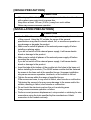
SAFETY PRECAUTIONS
(Read these precautions before using.)
When using Mitsubishi equipment, thoroughly read this manual and the
associated manuals introduced in the manual. Also pay careful attention to
safety and handle the module properly.
These precautions apply only to Mitsubishi equipment. Refer to the CPU
module user’s manual for a description of the PC system safety precautions.
These !SAFETY PRECAUTIONS! classify the safety precautions into two
categories: "DANGER" and "CAUTION".
DANGER
CAUTION
Procedures which may lead to a dangerous
condition and cause death or serious injury if not
carried out properly.
Procedures which may lead to a dangerous
condition and cause superficial to medium injury, or
physical damage only, if not carried out properly.
Depending on circumstances, procedures indicated by
CAUTION may
also be linked to serious results.
In any case, it is important to follow the directions for usage.
Store this manual in a safe place so that you can take it out and read it
whenever necessary. Always forward it to the end user.
[DESIGN PRECAUTIONS]
DANGER
• When controlling (changing data, program or operation status (status
control) in particular) a PC while it is running via a device such as a
personal computer connected to the special function module, configure an
interlock circuit in the sequence program so that the safety of the overall
system is always maintained.
Especially, when performing the above control for a remote PC from an
external device, troubles occurring on the PC side due to data
communication error may not be handled immediately. Determine error
handling methods between the external device and the PC CPU for when
data communication errors occur, in addition to configuring an interlock
circuit in the sequence program.
[DESIGN PRECAUTIONS]
CAUTION
• When laying AUI cable (transceiver cable)/coaxial cable, do not bundle
with or place near main circuit or power line.
Keep them at least 100 mm (3.94 in.) away from such cables.
Noise may cause erroneous operation.
[INSTALLATION PRECAUTIONS]
CAUTION
• Use the PC in the environment given in the general specifications section
of this manual. Using the PC outside the range of the general
specifications may result in electric shock, fire, or erroneous operation or
may damage or degrade the product.
• Make sure to switch all phases of the external power supply off when
installing or placing wiring.
If you do not switch off the external power supply, it will cause electric
shock or damage to the product.
• Make sure to switch all phases of the external power supply off before
mounting the module.
If you do not switch off the external power supply, it will cause electric
shock or damage to the product.
• Insert the tabs at the bottom of the module into the holes in the base unit
before installing the module. (The Q2AS series module shall be fastened
by screws in the base unit at the specified torque.) Improper installation
may cause erroneous operation, accidents, or the module to fall out.
• Tighten the screw within the range of specified torque.
If the screws are loose, it may result in fallout, short circuits or malfunction.
Tightening the screws to far may cause damage to the screw and/or the
module, resulting in fallout, short circuits or malfunction.
• Do not touch the electronic parts or the unit conducting area.
It may cause erroneous operation or failure.
• Perform correct pressure-displacement, crimp-contact or soldering for wire
connections using the tools specified by the manufactures. Attach
connectors to the module securely.
[WIRING PRECAUTIONS]
CAUTION
• Do not connect the AUI cable when the module installation station's power
is turned on.
• Make sure to secure communication cable and power supply cable
connected to the module is stored in the conduct or fixed with cramps.
Failure to do so may cause a malfunction or damage to the module or
cables due to dangling or inadvertent handling of cables.
• Tighten the screw within the range of specified torque.
If the screws are loose, it may result in short circuits or malfunction.
Tightening the screws to far may cause damage to the screw and/or the
module, resulting in fallout, short circuits or malfunction.
• Do not grab on the cable when removing the communication cable
connected to the module.
When removing the cable with a connector, hold the connector on the side
that is connected to the module.
Pulling the cable that is still connected to the module may cause a
malfunction or damage to the module or cable.
• Be sure that cuttings, wire chips, or other foreign matter do not enter the
module.
Foreign matter may start a fire or cause an accident or erroneous
operation.
[STARTING AND MAINTENANCE PRECAUTIONS]
DANGER
• Do not touch live terminals.
It may cause erroneous operation.
• Make sure to switch all phases of the external power supply off before
cleaning or retightening terminal screw.
If you do not switch off the external power supply, it will cause a damage to
a module or malfunction.
If the screws are loose, it may result in fallout, short circuits or malfunction.
Tightening screws too far may cause damages to the screws and/or the
module, resulting in fallout, short circuits or malfunction.
[STARTING AND MAINTENANCE PRECAUTIONS]
CAUTION
• Do not disassemble or rebuild the module.
It may cause accidents, erroneous operation, injury, or fire.
• Turn off the power before mounting and dismounting the module.
Mounting or dismounting the module while the power is on may damage
the module or cause erroneous operation.
[PRECAUTIONS WHILE OPERATING]
DANGER
• Do not write data in the "system area" in the buffer memory of the special
function module.
Also, of the output signals directed to the special function module from the
PC CPU, do not output (switch on) the signals that are "use-prohibited."
If data is written to the "system area" or output is performed with respect to
a "use-prohibited" signal, it may result in the malfunctioning of the PC
system.
CAUTION
• When controlling (changing data, program or operation status (status
control) in particular) a PC while it is running via a device such as a
personal computer connected to the special function module, read the
manual carefully and conform if the overall safety is maintained.
Failure to perform correct operations to change data, program, or the
status may result in system malfunction, machine damage or an accident.
• When performing remote RUN/STOP for the PC CPU on the station
loading this module (or the present station), it is recommended to read the
manual thoroughly and use the function stated as "data communication
when PC CPU is stopped."
If remote RUN/STOP is performed without using the "data communication
when PC CPU is stopped" function, the communication line will be
disconnected (by the close processing), since the output signal to this
module from the PC CPU turns off. Therefore, all data communication will
be disabled thereafter, including the remote RUN/STOP control of the PC
CPU from other nodes.
[DISPOSAL PRECAUTIONS]
CAUTION
• When disposing of this product, handle it as industrial waste.
Related Manuals
The following product are available for this equipment. Refer to the table given
below to choose suitable manuals.
Related Manual
Manual Name
Manual No.
(Model code)
Ethernet Interface Module User's Manual
Products of SH-3598-C
or later (13J856)
Please read Ethernet Interface Module User’s Manual (Details) before using
this module.
Correspondence to EMC DIRECTIVE
To make the PCs compliant with the EMC directive, refer to Chapter 2 "EMC
AND LOW-VOLTAGE DIRECTIVE" in the PC user's manual (Hardware).
* When the PC CPU user's manual (Hardware) does not include Chapter 2
"EMC AND LOW-VOLTAGE DIRECTIVE", refer to QnA Series CPU
Compatible High-Speed Accessing Basic Base Unit – Additional
Explanation for Product Conforming to EMC Standards (IB-68837)
(optional).
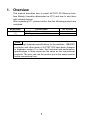
1. Overview
This manual describes how to install AJ71E71-S3 Ethernet Interface Module (hereafter abbreviated as E71) and how to wire them
with external devices.
After unpacking E71, please confirm that the following products are
contained.
Model name
AJ71E71-S3
(*1)
Product name
AJ71E71-S3 Ethernet Module
BCN T-type adapter (UG-274/u)
No. of items
1
1
Point
Even though hardware specifications for the switches, 10BASE2
connector and other areas of AJ71E71-S3 have been changed
in hardware version C or later, the functional and performance
specifications in those areas are the same as the conventional
products. The user can use the product just in the same manner
as the conventional one.
1
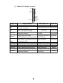
2. Performance Specifications
Performance Specifications of E71 are described below.
For general specification, refer to User’s Manual of CPU module to be used.
Specifications
10BASE2 (Cheaper10BASE5
net)
(Ethernet)
10 Mbps
Base band
Topic
Transmission
specifications
Sending/receiving communication data memory
for storage
Data transmission speed
Transmission method
Maximum distance
925 m (3034.77 ft.)
2500 m (8202.10 ft.)
between nodes
Maximum segment length
185 m (606.96 ft.)
500 m (1640.42 ft.)
Maximum number of
30 nodes per segment 100 nodes per segment
nodes
Minimum distance
0.5 m (1.64 ft.)
2.5 m (8.20 ft.)
between nodes
Fixed buffer
1 k word × 8
Random access buffer
3 k word × 2
Number of external nodes that can be
communicated with a single initial
processing
Max. 20 stations
* More external nodes can be connected
by repeating the initial processing.
Number of input output power points
5 V DC internal consumption current [A]
32 points
0.48 (When using 10BASE2)
0.26 (When using 10BASE5)
That which satisfies the
specifications of the
transceiver and the AUI
cable, considering the
voltage drop of the
module (Maximum 0.8 V)
12 V DC external power supply capacity
250 (9.84) × 37.5 (1.48) × 119 (4.69)
0.52 (1.144)
External dimensions [mm (inch)]
Mass [kg (lb)]
For general specification, refer to User's Manual of PC CPU to be used.
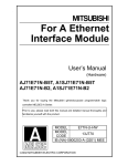
Notes
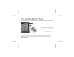
The following diagram indicates the longest between the modes,
and the segment length.
Segment length
Node Transceiver
Terminator
Node
Node
Repeater
Maximum
distance
between nodes
2
Node
Node
Segment length
Segment length
Repeater
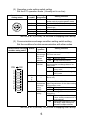
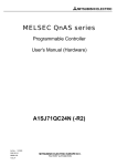
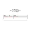
3. Settings and Names of Each Part
AJ71E71-S3
RUN
BUF 1
BUF 2
BUF 3
BUF 4
BUF 5
BUF 6
BUF 7
BUF 8
RDY
BSY
COM.ERR.
RAM CHK
RAM ERR.
ROM CHK
ROM ERR.
FROM/TO
(*1)
0:ONLINE
1:OFFLINE
2:TEST1
3:TEST2
4:TEST3
Display LED
SELFCHECK
S.C.ERR.
MODE
SW
ON
1
2
3
4
5
6
7
8
EXT.POWER
Operation mode setting switch
Communications exchange
condition setting switch
1) External power supply terminal
+12V
2) External supply power source
“ON” verification lamp
INPUT
12B
(FG)
3) Connector of the AUI cable
connection
10BASE 5
10BASE 5
10BASE 2
10BASE 2
4) The switch for 10 BASE5,
10 BASE2 switch over
5) Connector of the 10 BASE2
connection
*1 The seal shows the hardware version and software version of a
module.
(Example)
A
B
It shows that the software version is B.
It shows that the hardware version is A.
No.
Designation
Contents
1) External power source Power source terminals for power source supply to the
supply terminal
transceiver in the connection of 10BASE5.
* When connecting with 10BASE2, this connection is
unnecessary.
2) External power source Lamp for verifying if power is being supplied to the transceiver
supply "ON"
when used as 10BASE5.
verification lamp
* When connecting with 10BASE2, verification is unnecessary.
3) Connector of the AUI Connector for the connection of AUI cable (transceiver cable) for
cable connection
10BASE2 to E71.
4) The switch for
Switch for interface switch over of 10BASE5 and 10BASE2.
10BASE5, 10BASE2 At the time of shipping from the factory it is set to the 10BASE5
switch over
side.
5) Connector of the
Connector for the connection of coaxial cable for 10BASE2 to
10BASE2 connection E71.
3
(1) Display LED display contents
RUM
BUF1
BUF2
BUF3
BUF4
BUF5
BUF6
BUF7
BUF8
RDY
BSY
CCMERR
RAM CHK
RAM ERR.
ROM CHK
ROM ERR.
FROM/TO
SELFHCECK
S.C.ERR.
Display LED
RUN
Display contents
When lamp is lit
Lamp is not lit
Normal operation display
Normal
Abnormal
Standard display of communication
RDY
Light flashing during on-line operation
exchange completion
Display during execution of communiBSY
Executing
Not executing
cation exchange processing
Display of communication exchange During detection of ab- Normal (no
COM.ERR
abnormality detection
normality
abnormalities)
Display during data reading
During the execution of Not reading/
FROM/TO
(FROM)/display during data writing (TO) reading/writing
writing
BUF1
Display of telecommunication line conto
nection status of connection No.n cor- Open completed
Closed status
BUF8
responding to BUFn.
RAM CHK
Display during execution of RAM test During execution of test Not testing
RAM ERR.
RAM abnormality
Normal
Display of RAM abnormality detection
ROM CHK
Display during execution of ROM test During execution of test Not testing
ROM ERR.
ROM abnormality
Normal
Display of ROM abnormality detection
SELF CHECK Display during self back to back test During execution of test Not testing
Display of self back to back
Back to back
S.C.ERR.
Normal
abnormality detection
abnormality
4
(2) Operation mode setting switch setting
Set the E71 operation mode. (Usually set to on-line)
Operation mode
setting switch
67
F0 12
89
E
BCD
A
Setting
number
Setting
designation
0
On-line
1
2
Off-line
Test 1
3
4
5 to F
Test 2
Test 3
Setting contents
Execute communication exchange with
another node by regular operation mode.
Parallel off this module from network.
Execute self diagnosis from self back
to back test.
Execute RAM test.
Execute ROM test.
Use is impossible
345
This is set at “0 (on-line)” at the time of shipping from factory.
(3) Communications exchange condition setting switch setting
Set the conditions for data communication with other nodes.
Communications exchange
condition setting switch
Switch
1
2
SW
1
2
3
4
5
6
7
8
Setting designation
TCP time out
error temporary circuit
process
selection
Data code
selection
ON
3
to
6
7
8
CPU communications
exchange
timing
setting
Initial timing
setting
Setting contents
Selection of circuit processing when a
TCP time out error.
OFF Close the circuit.
ON Do not close the circuit.
Select a classification of data codes of
communication exchange data of another node.
OFF Communication exchange by
binary code.
ON Communication exchange by
ASCII code.
Use is impossible.
(Set to off)
During the RUN of PC CPU, select
approval/prohibition of the data reading
from another node.
OFF Writing prohibited.
ON Writing approved.
Select the timing which starts initial
processing.
OFF Quick start (start without delay)--when entirely constructed in a
single network.
ON Normal start (start after a 20 second delay)---when entirely constructed in multiple networks.
This is set at “0 (on-line)” at the time of shipping from factory.
5
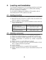
4. Loading and Installation
The following is explanations of the handling precautions and installation environment which is common to modules when handling
E71 from unpacking to installation.
For the details of loading and installation of the module, refer to
User’s Manual of PC CPU module to be used.
4.1
Handling precautions
The following is an explanation of handling precautions of the module.
(1) Because the case of the E71 is made of resin, be careful not to
drop it or expose it to strong impact.
(2) Execute tightening of the module's installation screws within the
range indicated below.
Screw position
Electrical supply cord
connection terminal screw (M4
screw)
Module fixing screw (Normally
unnecessary) (M4 screw)
4.2
Tightening torque range
98 to 137 N⋅cm (10 to 14 kg ⋅ cm)
(8.7 to 12.1 lb. ⋅ inch)
78 to 118 N⋅cm {8 to 12 kg ⋅ cm}
(6.9 to 10.4 lb. ⋅ inch)
Installation environment
Do not install the Q2AS series PC in the following environments.
(1) Where the ambient temperature exceeds the 0 to 55°C range.
(2) Where the ambient humidity exceeds the 10 to 99% RH range.
(3) Where condensation is produced by sudden temperature
changes.
(4) Where corrosive or combustible gas is present.
(5) Where dust, iron powder and other conductive powder, oil mist,
salt, or organic solvents are prevalent.
(6) In direct sunlight.
(7) Where a strong electric or magnetic field is generated.
(8) Where vibration and shock may be transmitted directly to the
module.
6
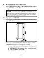
5. Connection to a Network
The following is an explanation of the connection method of the E71
to the 10BASE5 or the 10BASE2.
Point
Installation procedures of the 10BASE5 and 10BASE2 require
sufficient safety measures. For the execution of such operations
as terminal processing of connection cable, trunk line cable etc.,
please consult with a trained professional.
5.1
Connection to 10BASE2
The following is an explanation of the method of connecting the E71
to the 10BASE2 network.
[2] [1]
Diagram 5.1 Connection diagram of the coaxial cable for 10BASE2
Method of connecting the coaxial cable for 10BASE2
1) Line up the ratchet [2] with the groove [1] in diagram 5.1
while pushing it in.
2) While pushing in the connector, turn it 1/4 turn to the right.
3) Turn the connector until it locks.
4) Verify that the connector has locked.
7
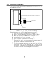
5.2
Connection to 10BASE5
The following is an explanation of the method of connecting E71 to
the 10BASE5 network.
Transceiver supply power source (Refer to Chapter 2)
A AUI Cable
Transceiver
B
Retainer
Diagram 5.2 AUI Cable connection diagram
Method of connecting the AUI cable (transceiver cable)*1
1) Slide the retainer in the A direction of diagram 5.2.
2) Plug in the AUI cable side connector as far as it will go.
3) Slide the retainer in the B direction of diagram 5.2.
4) Verify that the AUI cable is locked.
5) Input the power supply to the transceiver.*2
*1 Execute AUI cable connection when the power supply of
the module installation station is turned off.
*2 For the transceiver, generally use that which has the function called SQETEST or heartbeat (as a function of the
transceiver, a signal for confirming that the transceiver is
functioning normally after sending a communication)
8
Point
When connection to the network is made using the 10BASE5, if
countermeasures against high-frequency and noise generated in
the installation environment of E71 is necessary, attach a ferrite
core *3 to the transceiver side of the AUI cable to eliminate
these effects.
*3 ZCAT 2032-0930 manufactured by TDK can be used.
AUI
cable
Ferrite core
Coaxial cable
for 10BASE5
Transciver
9
2
4.2
(0.17)
(0.08)
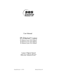
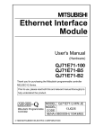
6. External Dimensions
AJ71E71-S3
RUN
BUF 1
BUF 2
BUF 3
BUF 4
BUF 5
BUF 6
BUF 7
BUF 8
RDY
BSY
COM.ERR.
RAM CHK
RAM ERR.
ROM CHK
ROM ERR.
SELFCHECK
S.C.ERR.
FROM/TO
0:ONLINE
1:OFFLINE
2:TEST1
3:TEST2
4:TEST3
MODE
SW
ON
1
2
3
4
5
6
7
8
250 (9.84)
EXT.POWER
+12V
INPUT
12B
(FG)
10BASE 5
10BASE 5
10BASE 2
4.2
(0.17)
106 (4.17)
13.3
(0.47)
12
10BASE 2
37.5 (1.48)
(0.52)
mm (inch)
10