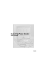
1
Model FRD100 Frequency Response Detector Hardware User’s Manual 197332B / 1103 Printed in U.S.A. FCC Notice This equipment generates, uses, and can radiate radio–frequency energy and, if not installed and used in accordance with this manual, may cause interference to radio communications. As temporarily permitted by regulation, operation of this equipment in a residential area is likely to cause interference, in which case the user at his own facility will be required to take whatever measures may be required to correct the interference. Company Names Princeton Applied Research is part of Advanced Measurement Technology, Inc, a division of AMETEK, Inc. It includes the businesses formerly trading as EG&G Princeton Applied Research, EG&G Instruments (Princeton Applied Research) and PerkinElmer Instruments (Princeton Applied Research) Declaration of Conformity This product conforms to EC Directives 89/336/EEC Electromagnetic Compatibility Directive, amended by 92/31/EEC and 93/68/EEC, and Low Voltage Directive 73/23/EEC amended by 93/68/EEC. This product has been designed in conformance with the following IEC/EN standards: EMC: BS EN55011 (1991) Group 1, Class A (CSPIR 11:1990) BS EN50082–1 (1992): IEC 801–2:1991 IEC 801–3:1994 IEC 801–4:1988 Safety: BS EN61010–1: 1993 (IEC 1010–1:1990+A1:1992) Trademarks AMETEK® and the 8 and logos are registered trademarks of AMETEK, Inc. Microsoft is a registered trademark, and Windows a trademark, of Microsoft Corporation Table of Contents Table of Contents Chapter One, Introduction 1.1 How to Use This Manual ............................................................................................................................ 1-1 1.2 What is a Frequency Response Detector?..................................................................................................... 1-1 1.3 Key Specifications and Benefits................................................................................................................... 1-2 Chapter Two, Installation & Initial Checks 2.1 Installation.................................................................................................................................................. 2-1 2.1.01 Introduction........................................................................................................................................ 2-1 2.1.02 Rack Mounting .................................................................................................................................. 2-1 2.1.03 Inspection........................................................................................................................................... 2-1 2.1.04 Line Cord Plug................................................................................................................................... 2-1 2.1.05 Line Voltage Selection and Line Fuses ................................................................................................ 2-1 2.2 Initial Checks.............................................................................................................................................. 2-3 2.2.01 Introduction........................................................................................................................................ 2-3 2.2.02 Initial Checks Software ...................................................................................................................... 2-3 2.2.03 Procedure........................................................................................................................................... 2-4 Appendix A, Specifications Appendix B, Connectors B1 Rear Panel Connections ...............................................................................................................................B-1 B.1.01 Line Power Switch.............................................................................................................................B-1 B.1.02 Line Power Input Assembly ...............................................................................................................B-1 B.1.03 RS232 Connector ..............................................................................................................................B-1 B.1.04 AUX RS232 Connector .....................................................................................................................B-2 B.1.05 GPIB Connector ................................................................................................................................B-2 B.1.06 DIGITAL OUTPUTS Connector .......................................................................................................B-2 B.1.07 REF TTL Connector..........................................................................................................................B-3 B.1.08 REF IN Connector.............................................................................................................................B-3 B.1.09 OSC OUT Connector.........................................................................................................................B-3 B.1.10 REF MON Connector ........................................................................................................................B-3 B.1.11 PRE-AMP POWER Connector ..........................................................................................................B-3 B.1.12 SIG MON Connector.........................................................................................................................B-4 B.1.13 CH1 and CH2 Connectors .................................................................................................................B-4 B.1.14 A and B/I Signal Input Connectors.....................................................................................................B-4 B.1.15 TRIG Connector ................................................................................................................................B-4 B.1.16 ADC 1 and ADC 2 Connectors ..........................................................................................................B-4 B.1.17 DAC 1 and DAC 2 Connectors ..........................................................................................................B-4 B.1.18 FAST X, FAST Y Connectors ...........................................................................................................B-4 i TABLE OF CONTENTS Appendix C, Cable Diagrams C1 RS232 Cable Diagrams .............................................................................................................................. C-1 Index Warranty ................................................................................................................................. End of Manual ii Introduction Chapter 1 1.1 How to Use This Manual The Model FRD100 Frequency Response Detector is normally supplied as part of a 7VMRGIXSR (TTPMIH 9IWIEVGL electrochemistry impedance measuring system. As such it is operated via the GPIB interface from the Electrochemistry PowerSUITE or other 7VMRGIXSR (TTPMIH 9IWIEVGL software packages, and consequently users do not usually need to concern themselves with any details of how to program the instrument. This manual therefore gives general instructions for verifying that the Model FRD100 is operating correctly, together with its specifications when used in standalone applications. The manual is split into the following chapters:Chapter 1 - Introduction Provides an introduction to the manual, briefly describes what a Frequency Response Detector is and the types of measurements it may be used for, and lists the major specifications of the FRD100. Chapter 2 - Installation and Initial Checks Describes how to install the instrument and gives a simple test procedure that may be used to check that the unit has arrived in full working order. Appendix A Gives the detailed specifications of the instrument Appendix B Details the pinouts of the connectors on the rear panel. Appendix C Shows the connection diagrams for suitable RS232 null-modem cables to couple the unit to PC operating under 32-bit Microsoft Windows or 100% compatible computer. New users are recommended to unpack the instrument and carry out the procedure in chapter 2 to check that it is working satisfactorily. Once this has been done the instrument can be connected to the associated 7VMRGIXSR (TTPMIH 9IWIEVGL potentiostat and controlling software, using the information supplied with these items. If at any stage in the future it is suspected that the FRD100 has a fault then the procedure in chapter 2 can be used again to help isolate the problem. 1.2 What is a Frequency Response Detector? In its most basic form a Frequency Response Detector (FRD) measures the gain (or attenuation) and phase shift of an external electrical network as a function of frequency. It includes a precision sinusoidal oscillator of programmable frequency and amplitude, the output of which is connected to the network under test, normally via the 1–1 Chapter 1, INTRODUCTION potentiostat. The resulting current and voltage are detected by the potentiostat and passed back to the FRD, where a process of digital multiplication and filtering is used to measure their amplitude and phase with respect to the oscillator signal. The controlling software can then use this information to calculate the resulting network complex impedance, and plot this as the frequency is swept over the desired range. Modern instruments, such as the model FRD100, include many extra features beyond this basic function. This built in flexibility means that although such features may not be exploited by current releases of the system software, they may well be used by future versions, giving the possibility of upgrading systems without having to replace hardware. In summary, the model FRD100 can function as a:- Frequency Response Measuring System Vector Voltmeter Phase Meter Transient Recorder Precision Oscillator Noise Measurement Unit These characteristics, all available in a single unit, make it an invaluable addition to any 7VMRGIXSR (TTPMIH 9IWIEVGL impedance measuring system. 1.3 Key Specifications and Benefits The 7VMRGIXSR (TTPMIH 9IWIEVGL Model FRD100 represents a significant advance in the application of DSP technology in the design of an FRD. Until recently, limitations in the available semiconductor devices have restricted the operating frequency range of such instruments to at most a few hundred kilohertz. The model FRD100, with its use of the latest technology, extends this limit to 2 MHz. What is more, it does this without compromising any other important specifications. Key specifications include: Frequency range: 0.001 Hz to 120 kHz Voltage sensitivity: 2 nV to 1 V full-scale Current input mode sensitivities: 2 fA to 1 µA full-scale 2 fA to 10 nA full-scale Line frequency rejection filter 1–2 Measurement of in-phase and quadrature components of the input signal, together with calculation of resulting magnitude and phase Very low phase noise of < 0.0001° rms Output time constants: 10 µs to 100 ks Chapter 1, INTRODUCTION Direct Digital Synthesizer (DDS) oscillator with variable amplitude and frequency Oscillator frequency and amplitude sweep generator 8-bit programmable digital I/O port for external system control Two auxiliary ADC inputs and two auxiliary DAC outputs Full range of auto-modes Standard IEEE-488 (GPIB) and RS232 interfaces 32,768 point internal curve storage buffer 1–3 Chapter 1, INTRODUCTION 1–4 Installation & Initial Checks Chapter 2 2.1 Installation 2.1.01 Introduction Installation of the model FRD100 in the laboratory or on the production line is very simple. It can be operated on almost any laboratory bench or be rack mounted, using the optional accessory kit, at the user's convenience. With an ambient operating temperature range of 0 °C to 35 °C, it is highly tolerant to environmental variables, needing only to be protected from exposure to corrosive agents and liquids. The instrument uses forced-air ventilation and as such should be located so that the ventilation holes on the sides and rear panels are not obstructed. This condition is best satisfied by leaving a space of at least 2" (5 cm) between the side and rear panels and any adjacent surface. 2.1.02 Rack Mounting An optional accessory kit, part number K02002, is available from 7VMRGIXSR (TTPMIH 9IWIEVGL to allow the model FRD100 to be mounted in a standard 19-inch rack. 2.1.03 Inspection Upon receipt the model FRD100 Frequency Response Detector should be inspected for shipping damage. If any is noted, 7VMRGIXSR (TTPMIH 9IWIEVGL should be notified immediately and a claim filed with the carrier. The shipping container should be saved for inspection by the carrier. 2.1.04 Line Cord Plug A standard IEC 320 socket is mounted on the rear panel of the instrument and a suitable line cord is supplied. 2.1.05 Line Voltage Selection and Line Fuses Before plugging in the line cord, ensure that the model FRD100 is set to the voltage of the AC power supply to be used. A detailed discussion of how to check and, if necessary, change the line voltage setting follows. CAUTION: The FRD100 may be damaged if the line voltage is set for 110 V AC operation and it is turned on with 220 V AC applied to the power input connector. 2–1 Chapter 2, INSTALLATION & INITIAL CHECKS The FRD100 can operate from any one of four different line voltage ranges, 90– 110 V, 110–130 V, 200–240 V, and 220–260 V, at 50–60 Hz. The change from one range to another is made by repositioning a plug-in barrel selector internal to the Line Input Assembly on the rear panel of the unit. Instruments are normally shipped from the factory with the line voltage selector set to 110–130 V AC, unless they are destined for an area known to use a line voltage in the 220–260 V range, in which case, they are shipped configured for operation from the higher range. The line voltage setting can be seen through a small rectangular window in the line input assembly on the rear panel of the instrument (figure 2-1). If the number showing is incorrect for the prevailing line voltage (refer to table 2-1), then the barrel selector will need to be repositioned as follows. Observing the instrument from the rear, note the plastic door immediately adjacent to the line cord connector (figure 2-1) on the left-hand side of the instrument. When the line cord is removed from the rear-panel connector, the plastic door can be opened outwards by placing a small, flat-bladed screwdriver in the slot on the right-hand side and levering gently. This gives access to the fuse and to the voltage barrel selector, which is located at the right-hand edge of the fuse compartment. Remove the barrel selector with the aid of a small screwdriver or similar tool. With the barrel selector removed, four numbers become visible on it: 100, 120, 220, and 240, only one of which is visible when the door is closed. Table 2-1 indicates the actual line voltage range represented by each number. Position the barrel selector such that the required number (see table 2-1) will be visible when the barrel selector is inserted and the door closed. Figure 2-1, Line Input Assembly VISIBLE # 100 120 220 240 VOLTAGE RANGE 90 110 200 220 – – – – 110 V 130 V 240 V 260 V Table 2-1, Range vs. Barrel Position Next check the fuse rating. For operation from a nominal line voltage of 100 V or 120 V, use a 20 mm slow-blow fuse rated at 2.0 A, 250 V. For operation from a nominal line voltage of 220 V or 240 V, use a 20 mm slow-blow fuse rated at 1.0 A, 250 V. 2–2 Chapter 2, INSTALLATION & INITIAL CHECKS To change the fuse, first remove the fuse holder by pulling the plastic tab marked with an arrow. Remove the fuse and replace with a slow-blow fuse of the correct voltage and current rating. Install the fuse holder by sliding it into place, making sure the arrow on the plastic tab is pointing downwards. When the proper fuse has been installed, close the plastic door firmly. The correct selected voltage setting should now be showing through the rectangular window. Ensure that only fuses with the required current and voltage ratings and of the specified type are used for replacement. The use of makeshift fuses and the short-circuiting of fuse holders is prohibited and potentially dangerous. 2.2 Initial Checks 2.2.01 Introduction The following procedure checks the performance of the FRD100. In general, this procedure should be carried out after inspecting the instrument for obvious shipping damage. NOTE: Any damage must be reported to the carrier and to 7VMRGIXSR (TTPMIH 9IWIEVGL immediately. In addition the shipping container must be retained for inspection by the carrier. Note that this procedure is intended to demonstrate that the instrument has arrived in good working order, not that it meets specifications. Each instrument receives a careful and thorough checkout before leaving the factory, and normally, if no shipping damage has occurred, will perform within the limits of the quoted specifications. If any problems are encountered in carrying out these checks, contact 7VMRGIXSR (TTPMIH 9IWIEVGL or the nearest authorized representative for assistance. 2.2.02 Initial Checks Software The FRD100 is supplied with a 3.5" floppy disk containing the Initial Checks software program and a model C01003 9-pin female to 9-pin male modem eliminator RS232 cable. A PC operating under 32-bit Microsoft Windows with a standard RS232 interface COM1 or COM2 port is required to run the software which provides a quick and simple check of some of the main operating parameters of the instrument and allows various instrument outputs to be measured. The program also allows the user to set the GPIB communications interface parameters if values other than the factory defaults are to be used. Note that before the initial checks procedure can be performed it is essential to establish proper RS232 communications between the host computer and the FRD100. If the supplied C01003 cable is not available, or unsuitable for the computer’s connectors, then please refer to appendix D, RS232 Cable Diagrams, for information on the correct cable type to be used with your computer. 2–3 Chapter 2, INSTALLATION & INITIAL CHECKS 2.2.03 Procedure 1) Ensure that the FRD100 is set to the line voltage of the power source to be used, as described in section 2.1.05 2) With the rear panel mounted power switch (located at the extreme left-hand side of the instrument when viewed from the rear) set to 0 (off), plug in the line cord to an appropriate line source. 3) Connect a 9-way RS232 cable to the connector on the FRD100’s rear panel marked RS232. Connect the other end of the RS232 cable to the host computer's COM1 or COM 2 RS232 connector. If the host computer has a 25-way connector then a 25-way to 9-way cable must be used or alternatively a 9-way to 25-way adapter used with a 9-way to 9-way cable. 4) Using a BNC cable, connect the OSC output connector to the A input connector on the rear panel of the FRD100. 5) Turn the FRD100 power switch to the I (on) position. 6) Turn on the host computer and wait for it to boot and display the Windows desktop. 7) Put the Initial Checks disk in the disk drive and use Run on the Start menu to start the program INITCHECKS.EXE 8) The Initial Checks program will now run. The opening screen will appear, as shown in figure 2-2. Figure 2-2, Initial Checks Procedure, Opening Screen Click the Next button to continue, which displays a second screen where the model number of the instrument being checked is entered. Click the FRD100 button and then click Next. The following screen shows the required connections, but since these have already been made, click the Next button again. This accesses the Program Options menu, shown in figure 2-3 below. 2–4 Chapter 2, INSTALLATION & INITIAL CHECKS Figure 2-3, Initial Checks Procedure, Program Options Menu 9) The instrument is supplied set to a GPIB address of 12 and with a GPIB termination of <CR><LF> character pair. In addition the GPIB line EOI asserted with the last character that is sent. If the unit will be used under GPIB control and if these settings are not acceptable then it is useful to adjust them at this stage. Click the Configure GPIB button to access the Configure GPIB menu, shown below in figure 2-4. Figure 2-4, Initial Checks Procedure, Configure GPIB Menu 10) Set the GPIB address and terminator settings as required. Note that when the Test Echo to RS232 port box is checked, commands sent to the instrument and responses from it via the GPIB interface are echoed to the RS232 port. This can be of use during program debugging but in normal use the option should not be selected. Once the required settings have been entered, click Back to return to the Program Options menu. 2–5 Chapter 2, INSTALLATION & INITIAL CHECKS 11) Click on the Initial Checks button to access the Perform Checks menu, shown below in figure 2-5. Figure 2-5, Initial Checks Procedure, Perform Checks Menu - Opening Screen 12) Click on the Start Checks button. The program automatically checks for and switches to the serial port (COM 1 or COM 2) to which the lock-in amplifier is connected. 13) Once communications have been established the Comments section shows a list of commands being sent to the FRD100 which set it to a defined state. Once this has happened, the signal magnitude and reference phase are shown in the lower section of the display, as shown in figure 2-6. Figure 2-6, Initial Checks Procedure, Perform Checks Screen – Outputs Displayed 14) Note that although the actual output readings may vary from those listed above, they should be close to 100 % full-scale (magnitude) and 0° (phase). If this is achieved then one can be reasonably confident that the FRD100 has not suffered 2–6 Chapter 2, INSTALLATION & INITIAL CHECKS any shipping damage and is in good working order. Click on the Next button to finish the procedure. Note: The FRD100 is factory set with a baud rate of 9600 and Echo enabled. The initial checks program can only implement a baud rate of either 9600 or 19200 and Echo handshaking. If Echo is not implemented then full communication will be lost. Therefore before any subsequent use of the Initial Checks disk, it is essential to make sure that the FRD100 is set for either 9600 or 19200 baud and Echo enabled. The Windows HyperTerminal program can be of use in such cases. 2–7 Chapter 2, INSTALLATION & INITIAL CHECKS 2–8 Specifications Appendix A Measurement Modes X Y R θ In-phase Quadrature Magnitude Phase Angle Noise The unit can measure and report via the bus the value of any of these outputs Harmonic Detection of signals at harmonics, n, of the reference frequency where n ≤ 32 Noise Measures noise in a given bandwidth centered at the reference frequency F Signal Channel Voltage Inputs Modes Full-scale Sensitivity Dynamic Reserve Impedance FET Device Bipolar Device Voltage Noise FET Device Bipolar Device CMRR Frequency Response Gain Accuracy Distortion Line Filter Grounding Current Input Mode Full-scale Sensitivity Low Noise Wide Bandwidth Dynamic Reserve Frequency Response Low Noise Wide Bandwidth Impedance Low Noise Wide Bandwidth A only or Differential (A-B) 2 nV to 1 V in a 1–2–5 sequence > 100 dB 10 MΩ // 30 pF 10 kΩ // 30 pF 5 nV/√Hz at 1 kHz 2 nV/√Hz at 1 kHz > 100 dB at 1 kHz degrading by 6 dB/octave 0.001 Hz to 120 kHz 0.5 % typ (full bandwidth) –90 dB THD (60 dB AC Gain, 1 kHz) attenuates 50, 60, 100, 120 Hz BNC shields can be grounded or floated via 1 kΩ to ground Low Noise or Wide Bandwidth 2 fA to 10 nA in a 1–2–5 sequence 2 fA to 1 µA in a 1–2–5 sequence > 100 dB (with no signal filters) –3 dB at 500 Hz –3 dB at 50 kHz < 2.5 kΩ at 100 Hz < 250 Ω at 1 kHz A-1 Appendix A, SPECIFICATIONS Noise Low Noise Wide Bandwidth Gain Accuracy (midband) Low Noise Wide Bandwidth Line Filter Grounding 13 fA/√Hz at 500 Hz 130 fA/√Hz at 1 kHz ≤ 0.6 % typ ≤ 0.6 % typ attenuates 50, 60, 100, 120 Hz BNC shield can be grounded or floated via 1 kΩ to ground Reference Channel TTL Input (REF TTL Mode) Frequency Range 1 mHz to 120 kHz Analog Input (EXT REF Mode – factory default) Impedance 1 MΩ // 30 pF Sinusoidal Input Level 1.0 V rms** Frequency Range 1 Hz to 120 kHz Squarewave Input Level 100 mV rms** Frequency Range 300 mHz to 120 kHz **Note: Lower levels can be used with the analog input at the expense of increased phase errors. Phase Set Resolution Accuracy Noise at 100 ms TC, 12 dB/octave Internal Reference External Reference Orthogonality Drift Acquisition Time Internal Reference External Reference 0.01º increments 0.5º typ < 0.0001º rms < 0.01º rms at 1 kHz 90º ±0.0001º < 0.01º/ºC below 10 kHz < 0.1º/ºC above 10 kHz instantaneous acquisition 2 cycles + 50 ms Reference Frequency Meter Accuracy 120 kHz > F > 40 kHz ±4 Hz 40 kHz > F > 400 Hz ±0.8 Hz at F = 40 kHz improving to ±0.008 Hz at F = 400 Hz 400 Hz > F > 1 mHz ±0.040 Hz at F = 400 Hz improving to better than ±0.0001 Hz at F = 1 mHz A-2 Appendix A, SPECIFICATIONS Demodulator and Output Processing Description 2 × 18-bit ADCs driving two DSP elements managed by a powerful 68000-series host processor Output Zero Stability Digital Outputs Displays Analog Outputs No zero drift on all settings No zero drift on all settings < 5 ppm/ºC Harmonic Rejection –90 dB Time Constants Digital Outputs Fast Outputs Roll-off 5 ms to 100 ks in a 1–2–5 sequence 10 µs to 640 µs in a binary sequence 6, 12, 18 and 24 dB/octave Synchronous Filter Operation Available for F < 10 Hz Offset Auto and Manual on X and Y: ±300 % FS Frequency Range Setting Resolution Absolute Accuracy 0.001 Hz to 120 kHz 0.001 Hz 25 ppm + 30 µHz Distortion (THD) –80 dB at 1 kHz Oscillator Amplitude Range Setting Resolution 1 mV to 500 mV 501 mV to 2 V 2.001 V to 5 V Accuracy 0.001 Hz to 60 kHz 60 kHz to 120 kHz Stability 1 mV to 5 V 1 mV 4 mV 10 mV ±0.3 % ±0.5 % 50 ppm/ºC Output Impedance 50 Ω Maximum Input Resolution Accuracy Input Impedance ±10 V 1 mV ±20 mV 1 MΩ // 30 pF Auxiliary Inputs A-3 Appendix A, SPECIFICATIONS Sample Rate ADC 1 only ADC 1 and 2 Trigger Mode Trigger input 40 kHz max 13 kHz max Int, ext or burst TTL compatible CH1 CH2 Outputs Function Amplitude Impedance X, Y, R, θ, Noise and auxiliary functions ±10 V 1 kΩ Fast X and Fast Y Outputs Time Constant Amplitude Update Rate Output Impedance ≤ 640 µs ±10 V 166 kHz nominal 1 kΩ Signal Monitor Amplitude Impedance ±10 V FS 1 kΩ Aux D/A Output 1, 2 Maximum Output Resolution Accuracy Output Impedance ±10 V 1 mV ±10 mV 1 kΩ Outputs 8-bit Digital Output Reference Monitor Output Waveform Impedance Power – Low Voltage 8 TTL compatible lines that can be independently set high or low to activate external equipment 0 to 3 V rectangular wave TTL-compatible ±15 V at 100 mA rear panel 5-pin 180° DIN connector for powering compatible preamplifiers Data Storage Data Buffer Size Max Storage Rate From FRD outputs From ADC A-4 32k 16-bit data points, may be organized as 1×32k, 2×16k, 3×10.6k, 4×8k, etc. up to 800 16-bit values per second up to 40,000 16-bit values per second Appendix A, SPECIFICATIONS Interfaces RS232, IEEE-488. A auxiliary RS232 port is provided to allow "daisy-chain" connection and control of multiple units from a single RS232 computer port. Power Requirements Voltage Frequency Power 110/120/220/240 VAC 50/60 Hz < 40 VA General Dimensions Width Depth Height With feet Without feet Weight 432 mm (17 ") 415 mm (16.4 ") 74 mm (2.9 ") 60 mm (2.4 ") 7.4 kg (16.3 lb) All specifications subject to change without notification A-5 Appendix A, SPECIFICATIONS A-6 Connectors Appendix B B1 Rear Panel Connections Figure B-1, Model FRD100 Rear Panel Layout As shown in figure B-1, the line power switch, line power voltage selector, two RS232 connectors, a GPIB (IEEE-488) connector, digital I/O port, preamplifier power connector and sixteen BNC signal connectors are mounted on the rear panel of the instrument. Brief descriptions of these are given in the following text. B.1.01 Line Power Switch CAUTION: The model FRD100 may be damaged if the line voltage is set for 110 V AC operation and it is turned on with 220 V AC applied to the power input connector. Please ensure that the line voltage selector is set to the correct line voltage before switching on. Press the end of the switch marked I to turn on the instrument's power, and the other end marked O to turn it off. B.1.02 Line Power Input Assembly This houses the line voltage selector and line input fuse. To check, and if necessary change, the fuse or line voltage see the procedure in section 2.1.05. B.1.03 RS232 Connector Figure B-2, RS232 and AUX RS232 Connector (Female) This 9-pin D type RS232 interface connector implements pins 1, 2, 3 and 7 (Earth Ground, Transmit Data, Receive Data, Logic Ground) of a standard DTE interface. To make a connection to a PC operating under 32-bit Microsoft Windows, it is normally sufficient to use a three-wire cable connecting Transmit Data to Receive Data, Receive Data to Transmit Data, and Logic Ground to Logic Ground. Appendix D shows the connection diagrams of cables suitable for computers with 9-pin and 25pin serial connectors. Pinouts for this connector are shown below: B-1 Appendix B, CONNECTORS Pin 2 3 5 7 Function RXD TXD GND RTS Description Data In Data Out Signal Ground Request to Send - Always +12 V All other pins are not connected B.1.04 AUX RS232 Connector This connector is used to link other compatible equipment together in a "daisy-chain" configuration. Up to 16 instruments can be connected in this way. Each unit must be set to a unique address. Pinouts for this connector are the same as those for the mian RS232 connector given above in section B.1.03 B.1.05 GPIB Connector The GPIB interface connector conforms to the IEEE-488 1978 Instrument Bus Standard. The standard defines all voltage and current levels, connector specifications, timing and handshake requirements. B.1.06 DIGITAL OUTPUTS Connector Figure B-3, Digital Outputs Connector This connector provides eight TTL output lines, each of which can be set high or low via the computer interfaces. It is most commonly used for controlling auxiliary apparatus, such as lamps, shutters and heaters. Each output line is capable of driving three LSTTL loads. The connector will mate with a 20-pin IDC header plug (not supplied). The pinout is as follows:Pin 1 2 3 4 5 6 7 8 9 10 11 12 13 14 15 B-2 Function Ground Ground D0 Ground D1 Ground D2 Ground D3 Ground D4 Ground D5 Ground D6 Appendix B, CONNECTORS 16 17 18 19 20 Ground D7 Ground TTL Trigger Input +5 V D0 = Least Significant Bit D7 = Most Significant Bit B.1.07 REF TTL Connector This connector is provided to allow TTL-compatible pulses to be used as the reference input, if the best possible phase accuracy at low external reference frequencies is required, when it usually gives better results than the REF IN connector. B.1.08 REF IN Connector This is the general purpose input connector for external reference signals. Note: If the best possible phase accuracy at low external reference frequencies is required, then a TTL reference signal should be applied to the rear panel REF TTL input instead. B.1.09 OSC OUT Connector This is the output connector for the internal oscillator and has a nominal impedance of 50 Ω B.1.10 REF MON Connector The signal at this connector is a TTL-compatible waveform synchronous with the reference. This output monitors correct reference channel operation but its polarity is not uniquely defined so that it does not necessarily show the correct phase relationship with the SIG MON output. B.1.11 PRE-AMP POWER Connector Figure B-2, Preamplifier Power Connector This connector supplies ±15 V at up to 100 mA and can be used for powering an optional remote preamplifier. Pinouts for this connector are shown below. B-3 Appendix B, CONNECTORS Pin 1 2 3 Function –15 V Ground +15 V Pins 4 and 5 are not connected. Shell is shield ground B.1.12 SIG MON Connector The signal at this connector is that immediately prior to the main analog-to-digital converter and after the preamplifier, line filter and anti-alias filters. B.1.13 CH1 and CH2 Connectors The signal at these connectors is an analog voltage corresponding to a selected output, such as X, Y, R, θ, etc., as set by the CH 1 n and CH2 n. The minimum time constant that can be used is 5 ms. The full-scale output voltage range is ±10.0 V B.1.14 A and B/I Signal Input Connectors The A connector is the signal input connector for use in single-ended and differential voltage mode. The B/I connector is the signal input connector for use in differential voltage mode (A-B) and is also the signal input connector when current input mode is selected. B.1.15 TRIG Connector This connector accepts a TTL-compatible input and can be used for triggering the digitization of the voltages present at the auxiliary analog-to-digital converters (ADCs) or for triggering data acquisition to the internal curve buffer. The input operates on the positive edge only. B.1.16 ADC 1 and ADC 2 Connectors The input voltages at these connectors are digitized and can be read via the ADC command. The input voltages are sampled and held when the ADC is triggered, with several different trigger modes being available. These modes can be set by the TADC command. The input voltage range is ±10.000 V and the resolution is 1 mV. B.1.17 DAC 1 and DAC 2 Connectors There are two digital-to-analog converter (DAC) output connectors. The output voltages at these connectors can be set by DAC command. The output range is ±10.000 V and the resolution is 1 mV. B.1.18 FAST X, FAST Y Connectors The signals at these two connectors are the X channel and Y channel output signals derived from a point after the first stage of output low-pass filtering. The maximum time constant that can be used is 640 µs, with a fixed slope of 6 dB/octave. B-4 Cable Diagrams Appendix C C.1 RS232 Cable Diagrams Users who choose to use the RS232 interface to connect the model FRD100 to a standard serial port on a computer will need to use one of two types of cable. The only difference between them is the number of pins used on the connector which goes to the computer. One has 9 pins and the other 25; both are null-modem (also called modem eliminator) cables in that some of the pins are cross-connected. Users with reasonable practical skills can easily assemble the required cables from parts which are widely available through computer stores and electronics components suppliers. The required interconnections are given in figures C-1 and C-2. Figure C-1, Interconnecting RS232 Cable Wiring Diagram C-1 Appendix D, CABLE DIAGRAMS Figure C-2, Interconnecting RS232 Cable Wiring Diagram C-2 Index Index ADC trigger input B-4 ADC1 connector B-4 ADC2 connector B-4 Auxiliary ADC's B-4 CH1 connector B-4 CH2 connector B-4 Curve storage trigger input B-4 DAC1 connector B-4 DAC2 connector B-4 Differential voltage input mode B-4 DIGITAL OUTPUTS connector B-2 FAST X connector B-4 FAST Y connector B-4 Fuses line 2-1 ratings 2-2 GPIB interface connector B-2 Initial checks 2-3 Input overload indicators B-4 Inspection 2-1 Key specifications 1-2 Line cord 2-1 Line power input assembly B-1 Line power switch B-1 Line voltage selection 2-1 Operating environment 2-1 OSC OUT connector B-3 PREAMP POWER connector B-3 Rack mounting 2-1 Rear panel layout B-1 REF IN connector B-3 REF MON connector B-3 REF TTL connector B-3 RS232 interface AUX RS232 connector B-2 connector B-1 SIG MON connector B-4 Signal input connectors B-4 Single-ended voltage input mode B-4 Specifications detailed listing of A-1 for auxiliary inputs A-3 for data storage buffer A-4 for demodulator A-3 for measurement modes A-1 for oscillator A-3 for outputs A-4 for reference channel A-2 for signal channel A-1 TRIG connector B-4 What is a Frequency Response Detector? 1-1 INDEX-1 Index 2 $GYDQFHG 0HDVXUHPHQW 7HFKQRORJ\ ,QF a/k/a 7VMRGIXSR (TTPMIH 9IWIEVGL, a subsidiary of AMETEK®, Inc. :$55$17< Princeton Applied Research* warrants each instrument of its own manufacture to be free of defects in material and workmanship. Obligations under this Warranty shall be limited to replacing, repairing or giving credit for the purchase price, at our option, of any instrument returned, shipment prepaid, to our Service Department for that purpose within ONE year of delivery to the original purchaser, provided prior authorization for such return has been given by an authorized representative of Princeton Applied Research. This Warranty shall not apply to any instrument, which our inspection shall disclose to our satisfaction, to have become defective or unworkable due to abuse, mishandling, misuse, accident, alteration, negligence, improper installation, or other causes beyond our control. This Warranty shall not apply to any instrument or component not manufactured by Princeton Applied Research. When products manufactured by others are included in Princeton Applied Research equipment, the original manufacturer's warranty is extended to Princeton Applied Research customers. Princeton Applied Research reserves the right to make changes in design at any time without incurring any obligation to install same on units previously purchased. THERE ARE NO WARRANTIES THAT EXTEND BEYOND THE DESCRIPTION ON THE FACE HEREOF. THIS WARRANTY IS IN LIEU OF, AND EXCLUDES ANY AND ALL OTHER WARRANTIES OR REPRESENTATIONS, EXPRESSED, IMPLIED OR STATUTORY, INCLUDING MERCHANTABILITY AND FITNESS, AS WELL AS ANY AND ALL OTHER OBLIGATIONS OR LIABILITIES OF PRINCETON APPLIED RESEARCH, INCLUDING, BUT NOT LIMITED TO, SPECIAL OR CONSEQUENTIAL DAMAGES. NO PERSON, FIRM OR CORPORATION IS AUTHORIZED TO ASSUME FOR PRINCETON APPLIED RESEARCH ANY ADDITIONAL OBLIGATION OR LIABILITY NOT EXPRESSLY PROVIDED FOR HEREIN EXCEPT IN WRITING DULY EXECUTED BY AN OFFICER OF PRINCETON APPLIED RESEARCH. 6+28/' <285 (48,30(17 5(48,5( 6(59,&( A. Contact the Customer Service Department (865–482–4411) or your local representative to discuss the problem. In many cases it will be possible to expedite servicing by localizing the problem. B. If it is necessary to send any equipment back for service, we need the following information. 1. Model number and serial number. 5. Your telephone number and extension. 2. Your name (instrument user). 6. Symptoms (in detail, including control settings). 3. Your address. 7. Your purchase order number for repair charges (does not apply to repairs in warranty). 4. Address to which the instrument should be returned. 8. Shipping instructions (if you wish to authorize shipment by any method other than normal surface transportation). C. U.S. CUSTOMERS Ship the equipment being returned to: Advanced Measurement Technology, Inc. 801 S. Illinois Avenue Oak Ridge, TN 37831 ATTN: Customer Service Phone: Fax: E-mail: 865–482–4411 865–483–2133 [email protected] D. CUSTOMERS OUTSIDE OF U.S.A. To avoid delay in customs clearance of equipment being returned, please contact the factory or the nearest factory distributor for complete shipping information. Copyright © 2003, Advanced Measurement Technology, Inc. All rights reserved. *Princeton Applied Research is a registered trademark of Advanced Measurement Technology, Inc. All other trademarks used herein are the property of their respective owners.