1
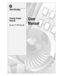
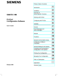
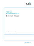
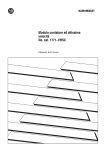
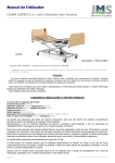
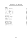
Installation Instructions Configurable Flowmeter Module (Catalog Number 1771-CFM) Contents Use this document as a guide when installing a Configurable Flowmeter module. To This icon is used when additional information is available in the Configurable Flowmeter Module User Manual, publication 1771Ć6.5.99. Important User Information Calculate power requirements Set the module operation jumpers See page 1 4 4 Set the input channel jumpers 5 Determine CFM module placement 6 Key the backplane connector 6 Install the module 7 Make connections to the field wiring arm 8 Ground the module 11 Configure the module 12 Interpret module status and input data 15 For this reference information Diagnostics Status indicators Specifications Important User Information See page 16 16 18 Because of the variety of uses for the products described in this publication, those responsible for the application and use of these products must satisfy themselves that all necessary steps have been taken to assure that each application and use meets all performance and safety requirements, including any applicable laws, regulations, codes and standards. In no event will Rockwell Automation be responsible or liable for indirect or consequential damage resulting from the use or application of these products. Any illustrations, charts, sample programs, and layout examples shown in this publication are intended solely for purposes of example. Since there are many variables and requirements associated with any particular installation, Rockwell Automation does not assume responsibility or liability (to include intellectual property liability) for actual use based upon the examples shown in this publication. Publication 1771ĆIN043B-EN-P - July 2002 2 Configurable Flowmeter Module Allen–Bradley publication SGI–1.1, Safety Guidelines for Application, Installation, and Maintenance of Solid–State Control (available from your local Rockwell Automation office), describes some important differences between solid–state equipment and electromechanical devices that should be taken into consideration when applying products such as those described in this publication. Reproduction of the contents of this copyrighted publication, in whole or part, without written permission of Rockwell Automation, is prohibited. Throughout this publication, notes may be used to make you aware of safety considerations. The following annotations and their accompanying statements help you to identify a potential hazard, avoid a potential hazard, and recognize the consequences of a potential hazard. WARNING ! ATTENTION Identifies information about practices or circumstances that can cause an explosion in a hazardous environment, which may lead to personal injury or death, property damage, or economic loss. Identifies information about practices or circumstances that may lead to personal injury or death, property damage, or economic loss. ! IMPORTANT Publication 1771ĆIN043B-EN-P - July 2002 Identifies information that is critical for successful application and understanding of the product. Configurable Flowmeter Module ATTENTION ! 3 Environment and Enclosure This equipment is intended for use in a Pollution Degree 2 industrial environment, in overvoltage Category II applications (as defined in IEC publication 60664–1), at altitudes up to 2000 meters without derating. This equipment is considered Group 1, Class A industrial equipment according to IEC/CISPR Publication 11. Without appropriate precautions, there may be potential difficulties ensuring electromagnetic compatibility in other environments due to conducted as well as radiated disturbance. This equipment is supplied as “open type” equipment. It must be mounted within an enclosure that is suitably designed for those specific environmental conditions that will be present, and appropriately designed to prevent personal injury resulting from accessibility to live parts. The interior of the enclosure must be accessible only by the use of a tool. Subsequent sections of this publication may contain additional information regarding specific enclosure type ratings that are required to comply with certain product safety certifications. See NEMA Standards publication 250 and IEC publication 60529, as applicable, for explanations of the degrees of protection provided by different types of enclosures. Also, see the appropriate sections in this publication, as well as the Allen–Bradley publication 1770–4.1, (“Industrial Automation Wiring and Grounding Guidelines”), for additional installation requirements pertaining to this equipment. Publication 1771ĆIN043B-EN-P - July 2002 4 Configurable Flowmeter Module ATTENTION ! Preventing Electrostatic Discharge This equipment is sensitive to electrostatic discharge, which can cause internal damage and affect normal operation. Follow these guidelines when you handle this equipment: • Touch a grounded object to discharge potential • • • • • Calculate Power Requirements static. Wear an approved grounding wriststrap. Do not touch connectors or pins on component boards. Do not touch circuit components inside the equipment. If available, use a static–safe workstation. When not in use, keep modules in appropriate static–safe packaging. Your CFM module receives its power through the 1771 I/O chassis backplane from the chassis power supply. The maximum current drawn by the CFM module is 0.8A. Add this value to the requirements of all other modules in the I/O chassis to prevent overloading the chassis backplane and/or backplane power supply. Setting the Module Operational Jumper ATTENTION ! CFM QRD QRC Publication 1771ĆIN043B-EN-P - July 2002 When using a 1771-P7 or 1771-PS7 power supply to power an I/O chassis, you cannot place more than four CFM modules in this chassis. The interaction between the four CFM modules and the 1771-P7 or 1771-PS7 power supply (not 16A limit) prevents the power supply from powering up. If you are using the 1771ĆCFM as a Set the jumper to replacement for a 1771ĆQRC module (no BTW / 3 word BTR) QRC replacement for a 1771ĆQRD module (1 word BTW / 9 word BTR) QRD CFM module (software configurable) CFM 19807 5 Configurable Flowmeter Module Set the Input Channel Jumpers These jumpers Are used to set flowmeter jumpers (F0ĆF3) flowmeter for lowĆpass filter (70Hz) or highĆspeed operation gate jumpers (G0ĆG3) gates for +5Ć12V or +12Ć30V operation The CFM module is configured for high-speed operation. If any input channel will be accepting input from a mechanical switch, you need to set the flowmeter jumper for that input channel to filter operation. The filter provides debouncing for the mechanical switch. ATTENTION ! 1 Remove the four screws securing the side cover to the module and remove the covers. 19805 2 Reposition the flowmeter and gate jumpers associated with each input channel according to your requirements The flowmeter and gate jumpers2 can be set independent of each other (you can select the filter action for each flowmeter input and a voltage for each and gate input independently). The frequency of counting must be less than 70Hz when the filter mode is selected. If the frequency exceeds 70Hz, the CFM module will not read the incoming pulse. 5-12V FILTER1 12-30V G0 HIGH SPEED F1 G1 F0 gate jumpers F3 G2 F2 flowmeter jumpers G3 19806 1 2 3 In the filter position, the module will not read frequencies above 70Hz. Jumpers are shown in default settings. Reposition the cover and secure with the four screws removed in step 1. 19813 Publication 1771ĆIN043B-EN-P - July 2002 6 Configurable Flowmeter Module Determine CFM Module Placement Use of data table Input Image Bits Output Image Bits Read Block Words Write Block Words Place your module in any slot of the I/O chassis except for the extreme left slot. This slot is reserved for processors or adapter modules. 8 8 41 max 60 max 2Ćslot addressing Place the CFM module in any Place the CFM module in any module group with any 8Ćbit or module group with any 8Ćbit, 8Ćbit bblock oc transfer a s e module. od e 16Ćbit 6 b oor bblock oc transfer a s e module. od e Key the Backplane Connector ATTENTION ! 1Ćslot addressing 1/2Ćslot addressing no restrictions The CFM module's printed circuit board is slotted in two places on the rear edge. These slots are intended to mate with the plastic keying bands supplied with the I/O chassis. Observe the following precautions when inserting or removing keys: • insert or remove keys with your fingers • make sure that key placement is correct Incorrect keying or the use of a tool can result in damage to the backplane connector and possible system faults. Position the keying bands in the backplane connectors to correspond to the key slots on the CFM module. Place the keying bands: S between 2 and 4 S between 6 and 8 19808 Publication 1771ĆIN043B-EN-P - July 2002 Configurable Flowmeter Module Install the Module WARNING ! ATTENTION ! 1 Place the module in the card guides on the top and bottom of the chassis that guide the CFM module into position. Important: Apply firm even pressure on the module to seat it into its backplane connector. When you insert or remove the module while backplane power is on, or you connect or disconnect the wiring arm with field power applied, an electrical arc can occur. This could cause an explosion in hazardous location installations. Be sure power is removed or the area is nonhazardous before proceeding. 1771ĆA1B, ĆA2B, ĆA3B, ĆA3B1, ĆA4B I/O chassis Snap the chassis latch over the top of the module to secure it. Remove power from the 1771 I/O chassis backplane before you install the CFM module. Failure to remove power from the backplane could cause: 1771ĆA1B, ĆA2B, ĆA3B1, ĆA4B Series B I/O chassis • injury • equipment damage due to Swing the chassis locking bar down into place to secure the modules. Make sure the locking pins engage. unexpected operation • degradation of performance At power-up, the active and fault indicators are on. An initial module self-check occurs. If there is no fault, the fault indicator turns off. See page 16 for information on interpreting the status indicators. The 1771–CFM module is a modular component of the 1771 I/O system requiring a properly installed system chassis. Refer to publication 1771–IN075 for detailed information on acceptable chassis, proper installation and grounding requirements. Limit the maximum adjacent slot power dissipation to 11W maximum. 19809 2 Attach the wiring arm (1771ĆWN) to the horizontal bar at the bottom of the I/O chassis. 1771ĆWN 17643 The wiring arm pivots upward and connects with the module so you can install or remove the module without disconnecting the wires. Publication 1771ĆIN043B-EN-P - July 2002 7 8 Configurable Flowmeter Module Make Connections to the Field Wiring Arm Even Numbered Terminals 2Ć40 Connect your I/O devices to the 40-terminal field wiring arm (cat. no. 1771-WN) shipped with the CFM module. Remove power to all I/O devices before you connect them to the wiring arm. Failure to remove power from your I/O devices could cause: ATTENTION ! • injury • damage to module circuitry • equipment damage due to unexpected operation not used 2 not used 4 G0 RET 6 G1 RET 8 F0 (500mV) 10 F0 Input 12 F1 (500mV) 14 F1 Input 16 dc source #1 @ 12mA RET (- proximity pickup) 18 dc source #2 @ 12mA RET (- proximity pickup) 20 F2 (500mV) 22 F2 Input 24 F3 (500mV) 26 F3 Input G2 RET 28 30 G3 RET 32 Output 0 Customer V dc #1 RET (Outputs 0 & 1 RET) The following tables and wiring diagrams represent wiring for a flowmeter input (F0), a gate input (G0), and an output (O0). See the wiring-arm diagram for the terminals used in wiring F1-F3, G1-G3, and O1-O3. F0 wiring Terminal signal input 12 signal common 11 Output 2 36 38 Customer V dc #2 RET (Outputs 2 & 3 RET) 40 1 Chassis GND 3 +5V dc RET 5 G0 7 G1 9 F0 (TTL) 11 F0 RET 13 F1 (TTL) 15 F1 RET 17 +24V dc source #1 @ 12mA 19 +24V dc source #2 @ 12mA 21 F2 (TTL) 23 F2 RET 25 F3 (TTL) 27 F3 RET 29 G2 31 G3 33 Customer V dc #1 (5 to 30V) 35 Output 1 37 Customer V dc #2 (5 to 30V) 39 Output 3 1771ĆWN Actual wiring runs in this direction. If multiple power sources are used, do not exceed the specified isolation voltage. For this threshold (ON/OFF) voltage Jumper 50 mV no jumper 500 mV 11 Ć 10 1.3 V 11 Ć 9 Publication 1771ĆIN043B-EN-P - July 2002 34 Odd Numbered Terminals 1Ć39 10689ĆI The sensor cable must be shielded. The shield: • must extend the length of the cable, but be connected only at the 1771 I/O chassis • must extend up to the point of termination Important: The shield should extend to the termination point, exposing just enough cable to adequately terminate the inner conductors. Use heat shrink or another suitable insulation where the wire exits the cable jacket. 9 Configurable Flowmeter Module Wiring Examples Standard Magnetic Pickup 50mV threshold (F0) Standard Magnetic Pickup 500mV threshold (F0) 1771ĆWN 1 3 5 7 9 F0 (TTL) Ċ not 1 used 1 F0 RET 2 4 6 8 10 12 not used Ċ F0 (500mV) F0 Input Input + Device - Important: To use a channel for 500mV sensor, jumper the 500mV pin to the appropriate RET. For Channel 0, jumper pin 10 to pin 11. 1 3 5 7 9 F0 (TTL) Ċ not 1 used 1 F0 RET 2 4 6 8 10 12 F0 (500mV) F0 Input Input + Device - À À Standard TTL or Open Collector 1.3V threshold (F0) 1771ĆWN Important: To use a channel in TTL, jumper the appropriate TTL pin to the appropriate RET. To use Channel 0 in TTL, jumper pin 9 to pin 11. 2 4 6 8 10 12 not used Ċ F0 (500mV) F0 Input Input + Device - 1771ĆWN 1 3 5 7 9 11 Standard Prover/Store Count (G0) 1771ĆWN external device G0 RET F0 (TTL) F0 RET 5-12V dc OR 12-30V dc + S 1 2 4 6 8 10 12 1 3 G0 5 7 9 11 À À Standard Proximity using CFM Module Source (F0) 1771ĆWN 2 4 6 8 not used Ċ F0 (500mV) 10 12 14 F0 16 Input 18 +24V dc source #1 @ 12mA RET (- proximity pickĆup) 20 + Input + - Device - 1 3 5 7 9 F0 (TTL) Ċ not used 11 F0 RET Ċ not used 13 +24V dc source #1 @ 12mA to power a proximity transducer 15 17 19 À À Publication 1771ĆIN043B-EN-P - July 2002 10 Configurable Flowmeter Module Wiring Examples (continued) Standard Output (O0) External + Power Supply #1 5Ć30V dc @ 2A - 28 30 32 34 36 38 40 À Output 0 + LOAD 0 - À + - Customer V dc #1 RET (Outputs 0 & 1 RET) 27 29 31 33 35 37 39 Customer V dc #1 (5 to 30V) Output 1 LOAD 1 À 1771ĆWN À For new installations, terminate the shields at the chassis. While not recommended, existing installations can continue to terminate the shields at the return (RET) terminal. If multiple power sources are used, do not exceed the specified isolation voltage. Alternate Wiring Method - Low-signal amplitude or High-noise applications lowĆsignal amplitude or highĆnoise applications For low-signal amplitude or high-noise applications, you can use this alternate wiring for your 1771-CFM/C module 1771ĆWN 2 4 6 8 input or output signal 10 12 input device + - conduit or other conductive enclosure Publication 1771ĆIN043B-EN-P - July 2002 1 3 5 7 9 11 signal RET 11 Configurable Flowmeter Module Ground the Module Use the following diagrams to ground your I/O chassis and CFM module. 1 Chassis Ground When you connect grounding conductors to the I/O chassis grounding stud, place a star washer under the first lug, then place a nut with captive lock washer on top of each ground lug. Torque the nut with captive washer to 18(+3) pound-inches. Remove a length of cable jacket from the Belden 8761 cable. ground lug nut 2 nut and captive washer grounding stud Pull the foil shield and bare drain wire from the insulated wires. star washer bare drain wire I/O chassis side plate insulated wires Twist the foil shield and drain wire together to form a single strand. 4 Attach a ground lug. shield and drain twisted together 19480 À Use the cup washer if crimpĆon lugs are not used. foil shield 3 ground lugÀ SingleĆpoint Grounding Extend shield to termination point. Expose just enough cable to adequately terminate inner conductors. Use heat shrink tubing or other suitable insulation where wire exits cable jacket. 20 20104 When using shielded cable wire, ground the foil shield and drain wire only at one end of the cable. We recommend that you wrap the foil shield and drain wire together and connect them to a chassis mounting bolt. At the opposite end of the cable, tape exposed shield and drain wire with electrical tape to insulate it from electrical contact. For additional grounding information, see the Industrial Automation Wiring and Grounding Guidelines, publication 1770-4.1. shield and drain twisted together #10 threadĆforming screw externalĆtooth washers 19923 Publication 1771ĆIN043B-EN-P - July 2002 12 Configurable Flowmeter Module Configure the Module To configure the CFM module, you enter BTW and BTR instructions into your ladder logic, then you enter data into the BTW instruction. This data should conform to the input device and specific application that you have chosen. You can configure the module using I/O configuration software or by editing bits in the BTW instruction. During normal operation, the processor transfers 1 to 60 words to the CFM module when you program a BTW instruction to the CFM module’s address. IMPORTANT You must program at least one BTW, with a word length of 4, to get useful data back from the CFM module. Your PLC processor gets data from the CFM module using BTR instructions in your ladder logic program. The CFM module transfers up to 41 words to the PLC processor’s data table file. The words contain module status and input data from each channel. You should program a block transfer read length of zero (0). When a BTR of 0 is programmed, the CFM module will determine the correct number of words (41) to return. Publication 1771ĆIN043B-EN-P - July 2002 Input Capabilities The CFM module accepts input for up to four channels (mode dependent). Each of the four input channels may accept these input signals: • magnetic pickup — 50mV to 30V ac • 3-30V dc pulses with open collector (TTL compatible) • proximity probe inputs – compatible with Bently Nevada 3300 (5mm and 8mm) proximity transducer systems – provides two isolated 24V dc power supplies (rated at 12mA) to power external devices Output Capabilities The CFM module has four assignable outputs. These outputs are designed for applications that require fast response. The outputs: • are electronically current limited to 2A • can be assigned to any input channel with user-selectable turn-on and turn-off values • are current sourcing at 5-30V dc (1A maximum per output) • must be connected to an external power supply • are in groups of two — this lets you use two separate external power supplies if desired (one for outputs 0&1 and one for outputs 2&3) Outputs may be forced on or off independent of count or frequency value. They may be forced on and off by setting bits in the BTW configuration block. IMPORTANT You can assign as many as four outputs to a given channel; however, you can not use the same output with two different channels. 13 Configurable Flowmeter Module Modes of Operation You configure the CFM module for these modes of operation: Prover Totalizer • accurately measure counts using a flowmeter or positive displacement meter • trigger outputs directly from the CFM module Ċ trigger on total, frequency, acceleration • monitor flow total, rate, and rate of change independent of your PLC processor scan times • store counts based on external input • scale the frequency and count to engineering units • interface to a prover Indicators/ Alarms overrange overflow overspeed acceleration √ Nonresettable Totalizer operate in the Totalizer mode with the count reset function disabled to prevent loss of accumulated value overrange overflow overspeed acceleration √ Use this mode To Total reset √ • monitor the frequency of an input with high accuracy (e.g. shaft) overspeed 1 • monitor the rate of speed change HighĆresolution Frequency overrange • operate outputs based on speed or (channels 0&1 or channels 2&3) acceleration rate of change • scale the frequency to engineering units • monitor the direction of shaft rotation • monitor rate of change and frequency overspeed Direction Sensor1 • trigger outputs based on direction, frequency, acceleration (channels 0&1 or channels 2&3) rate of change overrange • scale the frequency and count to engineering units 1 This mode uses two channels for one input (your input device is connected to F0 or F2, while F1 or F3 is unused). In this mode of operation Scaler values Rollover value √ √ √ √ √ √ You can assign outputs that are programmable to trigger Totalizer on total, rate, rate change (acceleration), total overflow or prover status Nonresettable Totalizer on total, rate, rate change (acceleration), total overflow or prover status HighĆresolution Frequency on frequency or frequency rate of change (acceleration) Direction Sensor on either CLOCKWISE or COUNTERĆCLOCKWISE direction, acceleration or frequency (outputs are triggered ON only) If you want to configure the module through I/O Configuration software (if you are using a PLCĆ5 family processor1) by editing bits at the address of the BTW instruction You enter the appropriate information on the CFM module edit screens. edit the data file addresses in the BTW instruction to match your particular application. Use the word assignments on page 14 to edit the bits that apply to your application(s). 1 See PLCĆ5 Programming Software I/O Configuration Manual, publication 6200Ć6.4.12, for supported processors. Publication 1771ĆIN043B-EN-P - July 2002 14 Configurable Flowmeter Module BTW Word Assignments Word(s)À BitÁ 15 14 13 12 11 10 09 08 07 06 05 04 03 02 01 00 Block ID & Resets 1 Header 2 Output 1 Trigger 3 Output 3 Trigger Prover Run Initialize Overflow Reset Total Reset Output 0 Trigger Tie Output 0 to Channel Output 2 Trigger Tie Output 2 to Channel Channel 1 Channel 0 Output 1 and Output 0 Trigger & Select Tie Output 1 to Channel Output 3 and Output 2 Trigger & Select Tie Output 3 to Channel Input Channel Operating Mode 4 Channel 3 Channel 0 (words 5Ć14) 5, 15, 25, 35 Frequency in 10ths Bandwidth Limit Sampling Termination 6, 16, 26, 36 Channel 2 Input Channel Configuration ÉÉÉÉ ÉÉÉÉ ÉÉÉÉ Channel 1 (words 15Ć24) 4x High Hz Prover Type Channel 2 (words 25Ć34) Debounce Filtering Channel 3 (words 35Ć44) Acceleration Calculation Time Minimum Frequency Sampling Time 7, 17, 27, 37 Number of Pulses to Terminate Sampling 8, 18, 28, 38 Highest Allowable Frequency 9, 19, 29, 39 Acceleration Alarm Value (what rate to trigger on) Frequency Scaler Multiplier 10, 20, 30, 40 Frequency Scaler Divisor 11, 21, 31, 41 Total Scaler Multiplier 12, 22, 32, 42 Total Scaler Divisor 13, 23, 33, 43 Rollover Value Ċ Most Significant Digit (0Ć999 x 10,000) 14, 24, 34, 44 Rollover Value Ċ Least Significant Digit (0Ć9,999) Output 0 (words 45Ć48) Output Configuration Output 1 (words 49Ć52) Output 2 (words 53Ć56) 45, 49, 53, 57 Output ON value Ċ Most Significant Digit (0Ć999 x 10,000) 46, 50, 54, 58 Output ON value Ċ Least Significant Digit (0Ć9,999) 47, 51, 55, 59 Output OFF value Ċ Most Significant Digit (0Ć999 x 10,000) 48, 52, 56, 60 Output OFF value Ċ Least Significant Digit (0Ć9,999) À Valid BTW lengths are: 0, 1, 2, 3, 4, 14, 24, 34, 44, 48, 52, 56, 60. Á ALL numeric values are in binary.  When scaling is used, all outputs are still controlled by the actual value not the scaled value. For detailed BTW descriptions, see chapter 4, (publication 1771Ć6.5.99). Publication 1771ĆIN043B-EN-P - July 2002 Output 3 (words 57Ć60) 15 Configurable Flowmeter Module Interpret Module Status and Input Data Your PLC processor gets data from the CFM module using BTR instructions in your ladder logic program. The CFM module transfers up to 41 words to the PLC processor’s data table file. The words contain module status and input data from each channel. You should program a block transfer read length of zero (0). When a BTR of 0 is programmed, the CFM module will determine the correct number of words (41) to return. BTR Word Assignments Word(s) Bit ÉÉÉÉÉÉ ÉÉÉÉÉÉÉÉÉÉÉÉÉÉÉÉÉÉÉÉÉÉ ÉÉÉÉÉÉ ÉÉÉÉÉÉÉÉÉÉÉÉÉÉÉÉÉÉÉÉÉÉ ÉÉÉÉÉÉ ÉÉÉÉÉÉÉÉÉÉÉÉÉÉÉÉÉÉÉÉÉÉ ÉÉÉÉÉÉÉÉÉÉÉ ÉÉÉÉÉÉÉÉÉÉÉ ÉÉÉ ÉÉ ÉÉÉ ÉÉ ÉÉÉ ÉÉ ÉÉÉ ÉÉ ÉÉÉ ÉÉ 15 14 13 12 11 10 09 08 07 06 05 04 03 02 01 00 Block ID & Resets 1 Header PowerĆup bit Output Status & Diagnostics 2 Output Status Error Words & Diagnostics Mode Indication 3 Channel 3 Channel 2 Channel 1 Channel 1 Status 4 Prover Status Overrange Alarm Channel 0 Status Overflow Status Overspeed Alarm Acceleration Alarm Overspeed Alarm Acceleration Alarm 5 Prover Status Channel 0 (words 6Ć14) Overrange Alarm Prover Status Channel 3 Status Overrange Alarm Channel 0 Overspeed Alarm Acceleration Alarm Overspeed Alarm Acceleration Alarm Channel 2 Status Overflow Status Prover Status Overrange Alarm Input Channel Data Channel 1 (words 15Ć23) Channel 2 (words 24Ć32) 6, 15, 24, 33 Percent of Full Scale (Rate % of High RPM value) 7, 16, 25, 34 Frequency (0Ć120 ) MSD 8, 17, 26, 35 Frequency (0Ć999) LSD 9, 18, 27, 36 Total MSD (0Ć999) ÉÉÉÉÉÉÉÉÉÉÉÉÉÉÉÉÉÉÉÉ ÉÉÉÉÉÉÉÉÉÉÉÉÉÉÉÉÉÉÉÉ ÉÉÉ ÉÉÉ 10, 19, 28, 37 Total LSD (0Ć9,999) 11, 20, 29, 38 Acceleration (rate of change of frequency) 12, 21, 30, 39 Overflow Status Channel 3 (words 33Ć41) Direction 13, 22, 31, 40 Prover Total Count Value or Store Count Value Ċ MSD (0Ć999) 14, 23, 32, 41 Prover Total Count Value or Store Count Value Ċ LSD (0Ć9,999) not used Overflow Status * Numeric values are in binary except for Diagnostics (word 2, bits 00Ć07)* For detailed BTR descriptions, see chapter 5, (publication 1771Ć6.5.99). Publication 1771ĆIN043B-EN-P - July 2002 16 Configurable Flowmeter Module Diagnostics and Troubleshooting The CFM module returns diagnostics to the PLC processor in words one and two of the BTR file. These diagnostics give you the word in the BTW configuration block that has caused an error to occur. In the event that there are multiple incorrect BTW words, the CFM module only returns the first incorrect word. IMPORTANT word 1 15 14 13 12 0 0 1 0 15 11 10 09 08 07 14 13 12 11 10 09 08 07 Output Status reflects current operating state of outputs. b12 = Output 0 b13 = Output 1 b14 = Output 2 b15 = Output 3 Status Indicators Indicators ACTIVE INPUTS/OUTPUTS F0 F1 F2 F3 G0 G1 G2 G3 O0 O1 O2 O3 STATUS S0 S1 S2 S3 S4 S5 S6 S7 06 05 04 03 02 01 00 PowerĆup Bit indicates if a valid BTW has occurred since powerĆup or since last switched from Program to Run mode. Header (CFM module ID) must be 0010. word 2 ÉÉÉÉÉÉÉÉÉÉÉÉÉÉ ÉÉÉÉÉÉÉÉÉÉÉÉÉÉ ÉÉÉÉÉ ÉÉÉÉÉ 06 05 04 03 VALUES: 0 = OFF 1 = ON 02 01 VALUES: 1= no or invalid BTW 0 = yes 00 Error Words & Diagnostics displays invalid BTW word number (0Ć60 BCD). 99 = invalid BTW length The CFM module provides these status indicators: If indicator Is ON ACTIVE the CFM module is successfully receiving power and operational INPUTS (F0ĆF3 & G0ĆG3) OUTPUTS (O0ĆO3) S1 STATUS FAULT Is OFF a. Check FAULT LED Ċ if on, follow the steps listed under if FAULT is ON. a signal is present at the designated input terminal b. Check the power supply. a signal is not present at the designated input terminal the module has commanded an output on the output is off PowerĆup Bit (BTR word 1, bit 00) is ON (=1) Ċ BTW hasn't occurred since powerĆup, or invalid BTW, or PLC processor in Program mode S2 BTW is occurring PowerĆup Bit (BTR word 1, bit 00) is OFF (=0) Ċ valid BTW has occurred since powerĆup or since last switched from Program to Run mode S3 BTR is occurring 1. Turn off power to the I/O chassis backplane and wiring arm. BTR is not occurring BTW is not occurring 2. Reseat the CFM module in the I/O chassis. FAULT 3. Restore power to the I/O chassis backplane and wiring arm. Important If the fault LED remains on, there may be an internal problem. Contact your local AllenĆBradley representative for additional assistance. Publication 1771ĆIN043B-EN-P - July 2002 normal operation Configurable Flowmeter Module 17 Hazardous Locations The following information applies when operating this equipment in hazardous locations: Products marked CL I, DIV 2, GP A, B, C, D" are suitable for use in Class I Division 2 Groups A, B, C, and D Hazardous Locations and nonhazardous locations only. Each product is supplied with markings on the rating nameplate indicating the hazardous location temperature code. When combining products within a system, the most adverse temperature code (lowest T" number) may be used to help determine the overall temperature code of the system. Combinations of equipment in your system are subject to investigation by the local Authority Having Jurisdiction at the time of installation. WARNING ! EXPLOSION HAZARD • Do not disconnect equipment unless power has been removed or the area is known to be nonhazardous. • Do not disconnect connections to this equipment unless power has been removed or the area is known to be nonhazardous. Secure any external connections that mate to this equipment by using screws, sliding latches, threaded connectors, or other means provided with this product. • Substitution of components may impair suitability for Class I, Division 2. • If this product contains batteries, they must only be changed in an area known to be nonhazardous. Informations sur l'utilisation de cet équipement en environnements dangereux: Les produits marqués CL I, DIV 2, GP A, B, C, D ne conviennent que une utilisation en environnements de Classe I Division 2 Groupes A, B, C, D dangereux et non dangereux. Chaque produit est livré avec des marquages sur sa plaque d'identification qui indiquent le code de température pour les environnements dangereux. Lorsque plusieurs produits sont combinés dans un systéme, le code de température le plus défavorable (code de température le plus faible) peut eatre utilisé pour déterminer le code de température global du systéme. Les combinaisons d'equipements dans le systéme sont sujettes à inspection par les autorités locales qualifiées au moment de l'installation. AVERTISSEMENT RISQUE D'EXPLOSION • Couper le courant ou s'assurer que l'environnement est classé non dangereux avant de débrancher l'équipement. • Couper le courant ou s'assurer que l'environnement est classé non dangereux avant de débrancher les connecteurs. Fixer tous les connecteurs externes reliés à cet équipement à l'aide de vis, loquets coulissants, connecteurs filetés ou autres moyens fournis avec ce produit. • La substitution de composants peut rendre cet équipement inadapté à une utilisation en environnement de Classe 1, Division 2. • S'assurer que l'environnement est classé non dangereux avant de changer les piles. ! Publication 1771ĆIN043B-EN-P - July 2002 18 Configurable Flowmeter Module Specifications Number of Input Channels 4 Module Location 1771ĆA1B, ĆA2B, A3B, ĆA3B1, ĆA4B (series A and B) I/O chassis 1771ĆAM1, ĆAM2 I/O chassis with integral power supply, adapter Maximum Count Value 0-9,999,999 (programmable) BTW Processing Time (worst case) 5.5ms Ċ on a configuration change Module Scan Time 1.3-5ms (depending on configuration and frequency) Maximum Input Frequency 100kHz @ flowmeter Input (maximum frequency is 120kHz Ć 100kHz @ gate input overrange occurs at 100kHz) Inputs per Channel 2 - flowmeter input Ċ used for all modes gate input Ċ used in Totalizer and Nonresettable Totalizer modes Flowmeter (F0-F3) Input Voltage 50mVĆ30V ac Ċ Magnetic Pickup 5Ć30V dc (TTL compatible) Bently 3300 5 & 8 mm Ċ Proximity Pickups Flowmeter (F0-F3) Input Impedance 5KΩ ± 30% resistive Gate (G0-G3) Voltage 5-12 and 12-30V dc Gate (G0-G3) Current 22mA maximum Number of Outputs 4 Maximum Output OffĆstate Leakage Current less than 300μA @ 30V dc Maximum OnĆstate Voltage Drop 0.6Ω x current Output Control Any number of outputs are assignable to any of 4 channels. One turn-on" value and one turn-off" value per output. Output Voltage 5 to 30V dc, customer supplied Output Current 1A per channel sourced out of module All outputs can be on simultaneously without derating. Output Switching Time outputs triggered by Total: turn ON < 100μs; turn OFF < 100μs all other turn ON and OFF times < 1ms Filtering (F0ĆF3 inputs) Ċ jumper selectable highĆspeed or lowĆpass filter jumper (filter = below 70Hz) Debouncing (G0ĆG3 inputs) Ċ software selectable 1s (approximate) between transitions with no minimum pulse width Ċ Totalizer and Nonresettable Totalizer modes only Module dc Source Output 24V dc; 12mA; ripple: ±5%; noise: 240mV peakĆtoĆpeak Backplane Current 0.8A maximum, 5V dc Customer Supply 5 to 30V dc Isolation Voltage Tested to withstand - for 60s 500V between input and backplane, 1500V between output and backplane, 500V between isolated channels, 1500V between isolated outputs and gates Module Power Dissipation 13W (maximum); 2W (minimum) Module Thermal Dissipation 54.2 BTU/hr (maximum); 6.8 BTU/hr (minimum) Maximum Adjacent Slot Power Dissipation 11W Input Conductors Wire Type Category Length Belden 8761 Category 21 304.8m (1000ft) Output Conductors Wire Size Category 14AWG (2.5mm2) solid or stranded copper wire rated @ 60oC or greater Category 21 Publication 1771ĆIN043B-EN-P - July 2002 Configurable Flowmeter Module 19 Environmental Conditions Operating Temperature IEC 60068-2-1 (Test Ad, Operating Cold) IEC 60068-2-2 (Test Bd, Operating Dry Heat) IEC 60068-2-14 (Test Nb, Operating Thermal Shock) 32 to 131°F (0o to 60oC) Storage Temperature IEC 60068-2-1 (Test Ab, Unpackaged, Nonoperating Cold) IEC 60068-2-2 (Test Bb, Unpackaged, Nonoperating Dry Heat) IEC 60068-2-14 (Test Na, Unpackaged, Nonoperating Thermal Shock) -40 to 185°F (-40 to 85oC) Relative Humidity IEC 60068-2-30 (Test Db, Unpackaged, Nonoperating Damp Heat) 5 to 95%, noncondensing Shock Operating Nonoperating IEC 60068-2-27 (Test Ea, Unpackaged Shock) 30g 50g Vibration IEC 60068-2-6 (Test Fc, Operating) 2g @ 10-500Hz ESD Immunity IEC 61000-4-2 4kV contact discharges Radiated RF Immunity IEC 61000-4-3 10V/m, with 1kHz sine-wave 80% AM from 30MHz to 1000MHz 10V/m, with 200Hz 50% Pulse 100%AM from at 900MHz EFT/B Immunity IEC 61000-4-4 +1kV @ 5kHz on signal ports Surge Transient Immunity IEC 61000-4-5 +2kV line-earth (CM) on signal ports Conducted RF Immunity IEC 61000-4-6 10V rms with 1kHz sine wave 80% AM from 150kHz to 30MHz Emissions CISPR 11 Group 1, Class A (with appropriate enclosure) Enclosure Type Rating None (open-style) Keying (lower backplane connector) Between 2 and 4 Between 6 and 8 Field Wiring Arm Catalog Number 1771ĆWN Wiring Arm Screw Torque 9 pound-inches (1.0Nm) User Manual Publication 1771-6.5.99 (See User Manuals on page 20.) Certifications (when product is marked) UL 1 2 UL Listed Industrial Control Equipment CSA CSA CSA Certified Process Control Equipment CSA Certified Process Control Equipment for Class I, Division 2 Group A, B, C, D Hazardous Locations European Union 94/9/EEC ATEX Directive, compliant with: EEx2 EN 50021; Potentially Explosive Atmospheres, Protection n" European Union 89/336/EEC EMC Directive, CE2 compliant with: EN 50082-2, Industrial Immunity EN 61236, Meas./Control/Lab., Industrial Requirements EN 61000-6-2, Industrial Immunity EN 61000-6-4, Industrial Emissions C-Tick2 Australian Radiocommunications Act, compliant with: AS/NZS 2064, Industrial Emissions You use this conductor category information for planning conductor routing as described in publication 1770Ć4.1, Industrial Automation Wiring and Grounding Guidelines. See the Product Certification link at www.ab.com for Declarations of Conformity, Certificates and other certification details Publication 1771ĆIN043B-EN-P - July 2002 20 Configurable Flowmeter Module European Zone 2 Certification This equipment is intended for use in potentially explosive atmospheres as defined by European Union Directive 94/9/CE. The LCIE (Laboratoire Central des Industries Electriques) certifies that this equipment has been found to comply with the Essential Health and Safety Requirements relating to the design and construction of Category 3 equipment intended for use in potentially explosive atmospheres, given in Annex II to this Directive. The examination and test results are recorded in confidential report No. 28 682 010. Compliance with the Essential Health and Safety Requirements has been assured by compliance with EN 50021 (1999). IMPORTANT Observe the following additional Zone 2 certification requirements: • This equipment is not resistant to sunlight or other sources of UV radiation. • The secondary of a current transformer shall not be open-circuited when applied in Class I, Zone 2 environments. • Equipment of lesser Enclosure Type Rating must be installed in an enclosure providing at least IP54 protection when applied in Class I, Zone 2 environments. • This equipment shall be used within its specified ratings defined by Allen-Bradley. • Provision shall be made to prevent the rated voltage from being exceeded by transient disturbances of more than 40% when applied in Class I, Zone 2 environments. User Manuals Thank you for purchasing this product. This product has a user manual associated with it. If you would like a manual, you can: S download a free electronic version from the internet:: www.ab.com/manuals or www.theautomationbookstore.com S purchase a printed manual by: – contacting your local distributor or Rockwell Automation representative, – visiting www.theautomationbookstore.com and placing your order – calling 1.800.963.9548 (USA/Canada) or 001.330.725.1574 (Outside USA/Canada) The publication number of the user manual for your product is listed under Specifications." CSA logo is a registered trademark of the Canadian Standards Association PLC is a registered trademark of AllenĆBradley Company, Inc. PLCĆ2/02, PLCĆ2/05, PLCĆ2/16, and PLCĆ2/17 are trademarks of AllenĆBradley Company, Inc. Europe/Middle East/Africa: Rockwell Automation, Brühlstraße 22, D-74834 Elztal-Dallau, Germany, Tel: (49) 6261 9410, Fax: (49) 6261 1774 Asia Pacific: Rockwell Automation, 55 Newton Road, #11-01/02 Revenue House, Singapore 307987, Tel: (65) 351 6723, Fax: (65) 355 1733 Publication 1771ĆIN043B-EN-P - July 2002 Supersedes Publication 1771-5.43 - April 1996 Publication 1771ĆIN043B-EN-P - July 2002 PN957689-89 Copyright 2002 Rockwell Automation, Inc. Printed in USA