1
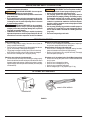
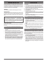
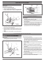
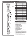
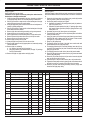
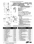
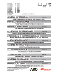
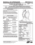
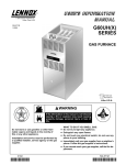
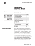
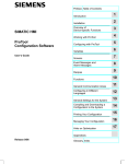
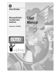
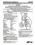
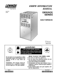
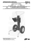
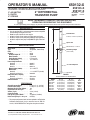
650132-X
OPERATOR’S MANUAL
650133-X
650137-X
INCLUDING: OPERATION, INSTALLATION & MAINTENANCE
INCLUDE MANUAL: SĆ632 GENERAL INFORMATION MANUAL (PN 97999Ć624)
2” DIFFERENTIAL
TRANSFER PUMP
2” AIR MOTOR
2:1 RATIO
6” STROKE
RELEASED:
8-3-71
REVISED:
12-10-02
(REV. T)
READ THIS MANUAL CAREFULLY BEFORE INSTALLING,
OPERATING OR SERVICING THIS EQUIPMENT.
It is the responsibility of the employer to place this information in the hands of the operator. Keep for future reference.
SERVICE KITS
• Use only genuine AROR replacement parts to assure compatible
pressure rating and longest service life.
• 66098 for repair of 60702 air motor section.
• 637044 for repair of lower pump end (Teflon upper and lower).
• 637045 for repair of lower pump end (UHMWĆPE upper and lower).
• 637355 for repair of lower pump end (UHMWĆPE upper / Teflon lowĆ
er).
60702 Air Motor
Air Inlet 1/4 Ć 18 N.P.T.F. (not shown)
A"
Spacer Tube
SPECIFICATIONS
Model Series . . . . . . . . . . . . . . . . .
Type . . . . . . . . . . . . . . . . . . . . . . .
Ratio . . . . . . . . . . . . . . . . . . . . . . .
Air Motor . . . . . . . . . . . . . . . . . . . .
Air Motor Repair Kit . . . . . . . . . .
Motor Diameter . . . . . . . . . . . . . .
Stroke (Double Acting) . . . . . . . .
Air Inlet (female) . . . . . . . . . . . . .
Lower Pump End Series
650132ĆX . . . . . . . . . . . . . . . . .
650133ĆX . . . . . . . . . . . . . . . . .
650137Ć1 . . . . . . . . . . . . . . . . .
Material Outlet (female) . . . . . . . . .
Material Inlet
650132ĆX . . . . . . . . . . . . . . . . . . .
650133ĆX and 650137Ć1 . . . . . . .
Pump Drum Size / Capacity
650132ĆX . . . . . . . . . . . . . . . . . . .
650133ĆX and 650137Ć1 . . . . . . .
Dimensional Data . . . . . . . . . . . . .
65013XĆX
Air Operated, Transfer Pump
2:1
60702
66098
2" (5.08 cm)
6" (15.24 cm)
1/4 Ć 18 N.P.T.F.
¬
(2 N.P.T. thread)
B"
``C" Lower Pump End
1 Ć 11Ć1/2 N.P.T.F. (female)
immersed
Wall mount
55 gallon
see chart
0 Ć 150 p.s.i. (0 Ć 10.3 bar)
0 Ć 300 p.s.i. (0 Ć 20.7 bar)
120
8.0
4.4 oz. (131 ml)
28.8
4.2 gallons (15.8 liters)
81 db(A)¬
The pump sound pressure level has been updated to an Equivalent
Continuous Sound Level (LAeq) to meet the intent of ANSI S1.
13Ć1971, CAGIĆPNEUROP S5.1 using four microphone locations.
INGERSOLL-RAND COMPANY
P.O. BOX 151 D ONE ARO CENTER D BRYAN, OHIO 43506Ć0151
& (419) 636-4242 D FAX (419) 633-1674
66670 Bung Adapter
66283ĆX
66281ĆX
66601Ć10
1/2 Ć 14 N.P.T.F.
PERFORMANCE
Air Inlet Pressure Range . . . . . . . .
Fluid Pressure Range . . . . . . . . . .
Maximum Rec'd Cycles / Minute . .
Displacement In3 Per Cycle . . . . . .
Volume / Cycle . . . . . . . . . . . . . . . .
Cycles Per Gallon . . . . . . . . . . . . .
Flow @ 120 Cycles / Minute . . . . . .
Noise Level @ 90 p.s.i. Ć 40 c.p.m. .
Material Outlet 1/2 Ć 14 N.P.T.F.
E2002 D PRINTED IN U.S.A.
Material Inlet
FIGURE 1
Accessories Available: 61113 Wall Mount Bracket.
MODEL
650132ĆC
650132Ć2C
650133
650133Ć1
650133Ć4
650133Ć5
650137Ć1
``A'' (mm)
41Ć1/2" (1054.1)
41Ć1/2" (1054.1)
52Ć7/8" (1343.0)
52Ć7/8" (1343.0)
52Ć7/8" (1343.0)
52Ć7/8" (1343.0)
53" (1346.2)
``B'' (mm)
22Ć3/8" (568.3)
22Ć3/8" (568.3)
33Ć3/4" (857.3)
33Ć3/4" (857.3)
33Ć3/4" (857.3)
33Ć3/4" (857.3)
33Ć7/8" (860.4)
``C"
66283
66283Ć3
66281
66281Ć1
66281
66281Ć3
66601Ć10
OPERATING AND SAFETY PRECAUTIONS
• Refer to General Information sheet for additional safety preĆ
cautions and important information.
WARNING EXCESSIVE AIR PRESSURE. Can cause personĆ
al injury, pump damage or property damage.
• Do not exceed the maximum inlet air pressure as stated on the
pump model plate.
• Be sure material hoses and other components are able to withĆ
stand fluid pressures developed by this pump. Check all hoses
for damage or wear. Be certain dispensing device is clean and
in proper working condition.
WARNING HAZARDOUS PRESSURE. Do not exceed maxiĆ
mum inlet air pressure of 150 p.s.i. (10.3 bar). Operating pump
at higher pressure may cause pump damage and / or personal
injury and / or property damage.
• COMPONENT RUPTURE. This pump is capable of producing
high material pressure as stated on pump model plate. Be sure
material hoses and other components are able to withstand
•
•
•
•
fluid pressures developed by this pump.
WARNING STATIC SPARK. Can cause explosion resulting in
severe injury or death. Ground pump and pumping system.
Sparks can ignite flammable material and vapors.
The pumping system and object being sprayed must be
grounded when it is pumping, flushing, recirculating or sprayĆ
ing flammable materials such as paints, solvents, lacquers,
etc. or used in a location where surrounding atmosphere is
conducive to spontaneous combustion. Ground the dispensĆ
ing valve or device, containers, hoses and any object to which
material is being pumped.
Use the pump grounding lug provided on metallic pumps for
connection of a ground wire to a good earth ground source.
Use Aro Part No. 66885Ć1 Ground Kit or a suitable ground wire
(12 ga. min.).
Use hoses incorporating a static wire.
TROUBLE SHOOTING
Pump continually cycles.
• Check for empty material supply. Disconnect the air (from the
pump), replenish material supply.
• Check to see if the connecting rod has disassembled from the matĆ
ing rod. See assembly of lower pump end (figure 4).
• The ball may be wedged or sticking open in the foot valve body.
NOTE: Replace the ball or the foot valve if either are damaged.
• Check for worn or damaged (32 or 46) upper packing.
Material on one stroke only (fast upstroke).
• Check for worn or damaged (37) lower material piston. Replace pisĆ
ton (see lower pump end instructions). See figure 7.
Material leakage out the top of the pump body.
• Check for worn or damaged (32 or 46) upper packing. See lower
pump end instructions and replace the upper packing.
• Remove (41) ball from the (42 or 43) foot valve body. Thoroughly
clean and replace (see figure 7).
Material on one stroke only (fast downstroke).
• The ball in the foot valve may not be checking or sealing properly.
Remove the ball from foot valve and inspect. If the ball or foot valve is
damaged, replace with new parts. If the ball or foot valve is not damĆ
aged, thoroughly clean both parts and reassemble (see lower pump
end instructions).
Air leakage out of the exhaust holes. (See Air Motor Instructions)
• Check to see if the (9) valve plate is loose or has disassembled from
the (11) spacer.
• Check for worn or damaged (10) piston.
• Check for worn or damaged (19) O" ring.
• Check for worn or warped (9) valve plate.
• Worn or damaged (14) O" ring. Replace (14) O" ring.
OPTIONAL ACCESSORIES
640081ĆB STRAP WRENCH
61113 BRACKET
FIGURE 2
PAGE 2 OF 8
650132ĆX
GENERAL DESCRIPTION
INSTALLATION
The Aro 2" differential 2:1 ratio transfer pumps have been designed for
the application and transfer of a wide range of corrosive and nonĆcorroĆ
sive materials. These pumps may be directly mounted in the 2" bung of a
standard drum or when using a 61113 mounting bracket, the pump can
be mounted on the wall or in an open head drum.
FLUSH PUMP
1. Connect fluid hose to pump outlet and be sure all fittings are tight.
2. Turn air regulator knob counterĆclockwise until it turns freely.
3. Pump has been tested in oil and a small amount remains for protecĆ
tion against rusting. Immerse lower pump end in compatible solvent.
4. Connect air hose coupler to connector on FRL.
5. Turn air regulator knob clockwise until air motor starts operating.
6. Flush pump with oil.
7. Disconnect air supply from air motor.
• CAUTION: Solvent used for flushing may not be compatible with
material being pumped. If this is the case, flush again with a compatĆ
ible solvent.
• If pump does not function properly, disconnect air and relieve all
pressure. Refer to Trouble Shooting.
AIR MOTOR
The 2" pump uses a differential, double acting style of air motor.
SPACER SECTION
The air motor is connected to the lower pump end by a spacer tube, this
protects the air motor section from possible contamination due to normal
wear and eventual leakage of material past the upper material piston
seals.
PUMP RATIO X
INLET PRESSURE TO PUMP MOTOR
=
MAXIMUM PUMP
FLUID PRESSURE
Pump ratio is an expression of the relationship between the pump motor area and the
lower pump end area. EXAMPLE: When 150 p.s.i. (10.3 bar) inlet pressure is supplied
to the motor of a 5:1 ratio pump it will develop a maximum of 750 p.s.i. (52 bar) fluid presĆ
sure (at no flow) Ć as the fluid control is opened, the flow rate will increase as the motor
cycle rate increases to keep up with the demand.
LOWER PUMP SECTION
Models covered by this manual have either threaded or unĆthreaded maĆ
terial inlets.
AIR AND LUBE REQUIREMENTS
• Do not operate pump continuously at speeds in excess of 75 cycles
per minute.
• Excessive air pressure will shorten the life of the pump.
• Use an air regulator to control operating pressure and cycle rate.
• Filtered and oiled air will allow the pump to operate more efficiently
and yield a longer life to operating parts and mechanisms.
• It is recommended that an oiler be installed in the airline as close as
possible to the pump. This increases the service life of the pump by
reducing wear of the air motor's internal parts.
• DAILY: Fill air line lubricator with a good grade of S.A.E. NO. 90
W nonĆdetergent gear oil, adjust to 1 to 2 drops per minute.
• Lack of or an excessive amount of lubrication will affect the perforĆ
mance and life of this pump. Use the recommended lubricants.
650132ĆX
OPERATING INSTRUCTIONS
1. Turn air regulator knob clockwise until air motor starts to cycle.
2. Allow pump to cycle slowly until it is primed and all air is purged from
the fluid hose or dispensing valve.
3. Turn off dispensing valve and allow pump to stallĆcheck all fittings for
leakage.
4. Change air regulator setting until desired pressure and flow is obĆ
tained.
5. Inspect airline filter, open petcock to flush moisture or residue from
bowl.
• If pump is to be inoperative for more than a few hours at a time, disĆ
connect air supply and relieve all pressure from the system.
MAINTENANCE
The basic pump consists of two major components: 1. Air Motor, 2. LowĆ
er Pump. The air motor is removable and is to be serviced separately.
Refer to air motor manual for service and parts. Disassembly should be
done on a clean work bench.
• Periodically flush entire pump system with a solvent that is compatĆ
ible with the material being pumped.
• Refer to disassembly procedures of air motor for correct breakdown.
• Before reassembling, lubricate parts where required. When reasĆ
sembling O" rings or parts adjacent to O" rings, care must be exerĆ
cised to prevent damage to O" rings and O" ring groove surfaces.
• SERVICING. Disconnect air lines and carefully bleed the pressure
off the system before servicing or cleaning pump, or removing fluid
hose or gun.
PAGE 3 OF 8
PUMP SERVICE PROCEDURES
PUMP DISASSEMBLY
Refer to Figure 3.
NOTE: All threads are right hand.
CAUTION: Do not clamp the pump tightly.
1. Thread a 1/2" nipple into the material outlet.
2. Place the 2" differential pump assembly in a vise as shown. Rotate
the pump assembly so that the 1/2" nipple is resting against the vise.
90826
76216
76208
FIGURE 4
PUMP REASSEMBLY
FIGURE 3
Refer to Figure 3.
1. Place the 2" air motor in a vise with the needle valve or pipe nipple
resting against the jaws of the vise, as shown.
2. Insert the 90826 tip of the lower assembly into the 76216 separating
tube of the air motor.
3. Insert the 90826 tip of the lower pump assembly through the outside
edge of the slot in the 76208 plunger tip, center the 90826 tip in the
76208 plunger tip and pull out until the 90826 tip is retained.
4. Thread the air motor into the material outlet body and tighten by usĆ
ing a strap wrench on the air motor 76216 separating tube.
3. Unthread the air motor from the material outlet body by using a strap
wrench on the air motor separating tube.
4. Push the connecting rod, in the lower pump assembly, to one side
and pull down until the air motor separates from the lower pump asĆ
sembly.
5. The pump is now in two assemblies: air motor and lower pump asĆ
sembly.
2” AIR MOTOR SERVICE PROCEDURES
2” AIR MOTOR DISASSEMBLY
Refer to Figure 5.
1. Place the air motor in the vise with a needle valve or a 1/4" pipe nipĆ
ple resting against the jaws of the vise, as shown.
FIGURE 5
PAGE 4 OF 8
NOTE: All threads are right hand.
2. Place a strap wrench around the (1) cap and remove the cap. NOTE:
If the (6) cylinder comes off with (1) cap, place the cap in a vise and
use a strap wrench around the cylinder and unscrew from cap.
NOTE: Do not squeeze or use pipe wrench on (6).
3. Place a strap wrench around the (6) cylinder and unscrew and reĆ
move the cylinder.
4. Pull the (7) assembly and (15) plunger out of the (18) body and lay
aside.
5. Remove the (17) spring and (16) O" ring from the (18) body.
6. Place the (18) body in the vise and loosen the (21) lock ring with a
strap wrench.
7. Place a strap wrench around the (22) separating tube and unthread.
8. Remove the (20) washer and (19) O" ring from the (18) body.
9. Clamp the flats of the (7) piston and spacer assembly in the vise. ReĆ
move the plunger tip from the (7) spacer and piston assembly.
NOTE: Do not remove the (13) plunger tip from the (15) plunger, unĆ
less replacing parts.
10. Remove the (12) gasket from the (13) plunger tip. NOTE: Do not mar
or damage o.d. of (15) plunger.
11. Remove the three (8) screws from the spacer and piston assembly.
12. Remove the (9) valve plate and (11) valve spacer.
650132ĆX
60702 2’’ AIR MOTOR PARTS LIST
ITEM DESCRIPTION
n SERVICE KIT PARTS
1
1 Cap
3
FIGURE 6
4
5
1
Y325Ć138
3 Spring
1
77208
4 Button
1
90638
5 Washer
1
77290
6 Cylinder
1
76074Ć2
1
61088
8 Screw (#4 Ć 40 x 3/8")
3
Y222Ć54ĆC
9 Valve Plate
1
76090
10 Piston Assembly
1
60656
11 Valve Spacer
1
76856
1
F21Ć53
13 Plunger Tip
1
76208
14 O" Ring (1/8" x 1Ć1/4" o.d.)
1
Y325Ć214
15 Plunger
1
76215
1
Y325Ć134
17 Spring
1
76070
18 Pump Body
1
76077Ć2
1
77803
20 Washer
1
76075
21 Lock Ring
1
76100
22 Separating Tube
1
76216
n 12 Gasket
8
9
7
n 16 O" Ring (3/32" x 2Ć1/16" o.d.)
11
12
13
14
15
16
17
18
19
20
21
22
93005
Ground Screw
650132ĆX
66098
76073Ć2
n 7 Spacer & Piston Assembly
6
PART NO.
1
n 2 O" Ring (3/32" x 2Ć5/16" o.d.)
2
10
QTY
n 19 O" Ring (.275" x 1.837" o.d.)
2” AIR MOTOR REASSEMBLY
Refer to Figure 6.
1. Insert the (11) valve spacer through the bottom of the (10) piston asĆ
sembly.
2. Place the (9) valve plate on top of the piston assembly (side with
three protrusions) to face (10) piston and align the three holes with
the three posts of the (11) spacer.
3. Fasten the valve plate down with the three (8) screws (this is the (7)
spacer and piston assembly). Lay aside.
4. Thoroughly grease the (19) O" ring and place into the (18) body.
5. Place the (20) washer in the (18) body.
6. Screw the (22) separating tube securely to the (18) body.
7. Tighten the (21) lock ring.
8. Grease the (16) O" ring and place over the threads of the (18) body.
9. Place the (17) spring into the (18) body.
10. Place the (15) plunger with (13) plunger tip through the (22) spacer
tube and through the (18) body.
NOTE: To prevent damage to (19) O" ring, apply light film of grease on
(15 and 13) assembly.
11. Place the (12) gasket over the threads of (13) plunger tip.
12. Screw the (7) spacer and piston assembly onto the (13) plunger tip
and tighten with wrenches, using flats provided.
13. Thoroughly grease the inside of the (6) cylinder and insert it over the
(7) spacer and piston assembly.
14. Thread the (6) cylinder on the (18) body.
15. Screw the (1) cap, with (2) ring, (3) spring, (4) button and (5) washer,
in place on the (6) cylinder and tighten with a strap wrench.
PAGE 5 OF 8
LOWER PUMP SERVICE PROCEDURES
LOWER PUMP DISASSEMBLY
LOWER PUMP END REASSEMBLY
Refer to Figure 7.
NOTE: All threads are right hand.
CAUTION: Do not place wrench any other place other than the
knurled part of the (33) suction tube.
1. Clamp the lower pump assembly in the vise, clamping on solid part
of (26) pump body. NOTE: Do not clamp directly on outlet hole.
2. Place a pipe wrench or strap wrench on the knurled part of the (33)
suction tube and remove the suction tubes.
3. Grasp the (34) lower piston rod and remove the rod and piston asĆ
sembly by pulling straight out.
4. Place a pipe wrench or strap wrench on the knurled part of the (28)
inner suction tube and remove.
5. Remove (25) tube and bushing assembly, using a strap wrench.
6. Clamp the (42 or 43) foot valve on flats in vise.
7. Place a pipe wrench on the knurled portion of (33) suction tube.
8. Remove (33 and 35) suction tubes from (42 or 43) foot valve.
9. Remove (42 or 43) foot valve from vise.
10. Remove (40) ball stop and (41) ball.
11. Clamp the (34) lower piston rod in the vise on flats.
12. Remove (29) cotter pin and (27) upper piston rod, remove by turning
counterĆclockwise.
13. Remove (30) nut, releasing
a. (31) washer, (32) seal and (31) washer or
b. (44) spring washer, (45) female washer, four (46) ``V" packings
and (47) male washer.
14. Remove the (39) nut, (38) washer and (37) piston.
Refer to Figure 7.
CAUTION: Apply Loctite Nickel antiĆseize compound to all stainless
steel threads unless the service manual calls for Loctite 271 threadlockĆ
er.
1. Clamp the (34) lower piston rod on flats in vise, put the (36) washer
and (37) piston in place as shown (lips up).
2. Put the (38) washer and (39) nut in place.
3. a. Assemble (31) washer, (32) seal (lips down) and (31) washer to
(34) lower piston rod or
b. Assemble (47) male washer, four (46) ``V" packings (lips down),
(45) female washer (lips down) and (44) spring washer to (34)
lower piston rod.
4. Assemble (30) nut to (34) lower piston rod and tighten.
5. Thread the (27) upper piston rod into (34) lower piston rod until the
cotter pin holes line up.
6. Insert (29) cotter pin and bend legs apart (flatten legs and head).
CAUTION: Be sure to flatten cotter pin, as shown in cross section
(see figure 7), to prevent damage to packings.
7. Clamp on (26) pump body.
8. Thoroughly grease the inside of the (28) inner suction tube and
thread securely into the (26) pump body.
9. Thoroughly grease the (32, 37 and 46) packings, insert the (27) upĆ
per piston rod through the (28) inner suction tube and (26) pump
body, (24) tip end first.
10. Thoroughly grease the inside of the (33 and 35) suction tubes.
11. Place the (33 and 35) suction tubes over the (37) piston and thread
into the (26) pump body.
12. Place the (41) ball into the (42 or 43) foot valve. Insert the (40) ball
stop into the (42 or 43) foot valve.
13. Thread the (42 or 43) foot valve into the (33 or 35) suction tube.
14. Tighten the lower pump section by placing a bar in the bottom slot in
the (43) foot valve or a wrench on the flats of (42) foot valve.
15. Place the (25) tube and bushing assembly over the (24) tip and
thread into the (26) pump body.
LOWER PUMP END PARTS LIST
ITEM DESCRIPTION (Size in inches)
QTY
PART NO. [MTL]
ITEM DESCRIPTION (Size in inches)
24 Connecting Rod Tip
(1)
90826
[C]
Y=37
25 Tube and Bushing Assembly
(1)
66280
[SS]
~
26 Pump Body
(1)
91821
[SS]
38 Washer
27 Upper Piston Rod
(1)
91812
[SS]
28 Inner Suction Tube
(1)
91814
29 Cotter Pin (3/32" o.d. x 3/4" long)
(1)
30 Nut (5/16" Ć 18)
31 Washer
Y=~
= 32
Seal
~
QTY
PART NO. [MTL]
(66281, 66283, 66601Ć10)
(1)
91484
[T]
(66281Ć1, 66281Ć3, 66283Ć3)
(1)
91523
[UH]
(1)
91489
[SS]
39 Nut (3/8" Ć 24)
(1)
Y115Ć14
[SS]
[SS]
40 Ball Stop
(1)
90825
[SS]
Y15Ć32ĆS
[SS]
41 Ball (.8125" dia.)
(1)
90815
[SS]
(1)
Y108Ć5ĆS
[SS]
42 Foot Valve Body (66283ĆX)
(1)
90932
[SS]
43 Foot Valve Body (66281ĆX, 66601Ć10)
(2)
91487
(1)
90823
[SS]
(models 66281, 66283, 66601Ć10)
(1)
93848Ć2
[T/SS]
Y 44
Spring Washer (66281Ć3, 66283Ć3)
(1)
96033
[SH]
(models 66281Ć1)
(1)
93848Ć1
[UH/SS]
Y 45
Female Washer (66281Ć3, 66283Ć3)
(1)
95331
[SS]
(66281ĆX)
(1)
91817
[SS]
Y 46
``V" Packing (66281Ć3, 66283Ć3)
(4)
95330Ć4
[UH]
(66283ĆX)
(1)
91820Ć2
[SS]
Y 47
Male Washer (66281Ć3, 66283Ć3)
(1)
95332
[SS]
(66601Ć10)
(1)
92443Ć2
[SS]
48 ``O" Ring (66601Ć10 only)
(1)
91189
[T]
(1)
91811
[SS]
=
Items included in service kit
637044
33 Suction Tube
34 Lower Piston Rod (66281ĆX, 66601Ć10)
[SS]
Piston
(66283ĆX)
(1)
91819Ć2
[SS]
~
Items included in service kit
637045
35 Suction Tube (66601Ć10 only)
(1)
92442
[SH]
Y
Items included in service kit
637355
36 Washer
(1)
91816
[SS]
PAGE 6 OF 8
650132ĆX
LOWER PUMP END PARTS LIST
24
k
25
l Use Loctite #271 threadlocker on these threads.
s Use Teflon tape and Nickel antiĆseize on these threads.
k
MATERIAL CODE
26
[C] = Carbon Steel
[SH] = Hard S'Steel
[SS] = Stainless Steel
[T] = Teflon
[UH] = UHMWĆPE
27
Cotter Pin needs to be installed as
shown. Flatten the head and legs.
s
28
29
30
44
33
31
45
32
46
31
47
48
6628XĆ3 ONLY
35
33
34
36
37
38
s
40
66601Ć10 ONLY
41
39
s
40
41
43
42
FIGURE 7
650132ĆX
PAGE 7 OF 8
PN 97999Ć34
PAGE 8 OF 8
650132ĆX