1
Preface, Table of Contents
SIMATIC HMI
ProTool
Configuration Software
Introduction
1
Installation
2
Overview of
Device-Specific Functions
3
Working with ProTool
4
Configuring with ProTool
5
Variables
6
Screens
7
Event Messages and
Alarm Messages
8
Recipes
9
User’s Guide
Functions
10
General Communication Areas
11
Configuring in Different
Languages
12
General Settings for the System
13
Compiling and Downloading a
Configuration to the System
14
Printing Your Configuration
15
Managing Your Configuration
16
Hints on Optimization
17
Appendices
Release 9/96
Glossary, Index
Trademarks
SIMATIC is a registered trademark of SIEMENS AG.
Microsoft, MS and MS-DOS are registered trademarks, and Windows is a trademark of
Microsoft Corporation in the United States and other countries.
Copyright
Subject to change without prior notice.
Copyright Siemens AG 1995 All Rights Reserved
Although the contents of this publication have been checked for agreement with the hardware and software described, we do not accept liability for total agreement since differences cannot be completely excluded.
The information in this publication is checked at regular intervals and
necessary corrections included in the next release. Your suggestions for
improving this publication are welcome.
Passing on and reproduction of these documents, and utilization and disclosure of their contents is prohibited unless specifically authorized.
Violations shall be cause for damage liability.
All rights reserved, particularly in the event a patent is issued or a utility
model patent is registered.
Preface
Purpose
With ProTool, you perform system-specific configuration for Operator Panels
(OPs) having graphics displays. The ProTool User’s Guide explains the way
in which you use the ProTool configuration tool and what configuring involves. The manual is applicable to the Operator Panels
– OP37,
– OP25,
– OP35 and
– OP45.
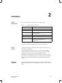
How it fits in
This manual is part of the SIMATIC HMI documentation. The documentation
includes the mauals for the configuration tool, the Operator Panels and communciation between the PLC and the OP. Below, you will find an overview
diagram and a description of when you require the different manuals.
PC
Configuration
OP
Installation
Operation
!
!
PLC
Connection
ProTool User’s Guide
Release 09/96
"
i
Preface
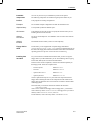
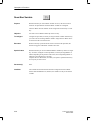
Document Type
Getting started
Product brief
Target Group
Beginners
Contents
This document guides you step by step through the
configuration of
a screen containing static text
a screen containing an input/output field
and a bar graph
changing from one screen to another
a message
A document is available for each of the following:
– OP3, OP5, OP15
– OP7, OP17
– OP25, OP35, OP45
ProTool
User’s Guide
Configurer
Provides information for working with the ProTool
configuring tool.
It contains
basic rules for configuration
a detailed description of objects and functions that
you can configure
examples of configuring objects
This document is valid for OPs having graphics displays.
ProTool/Lite
User’s Guide
Configurer
Same contents as the ProTool User’s Guide. This
document is valid for OPs having text based displays.
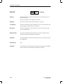
ProTool
Online Help
Configurer
Provides information on your computer (PU or PC)
screen for working with the ProTool configuring tool.
The online Help is context-sensitive and contains
a general description of the editors to be found in
ProTool
a detailed description of the different fields in the
dialog boxes
a comprehensive description of the functions
Application Example
Commissioning
Instructions
Beginners
Example configurations are supplied with ProTool
together with the associated PLC programs. This document describes
how you load the examples onto the OP and the
PLC
how you can run the example
how you can upgrade the connection for your
application
ii
ProTool User’s Guide
Release 09/96
Preface
Document Type
OP37
Equipment Manual
Target Group
Commissioning
engineers, users
Contents
Describes the OP hardware and general operation. It
contains
OP25, OP35, OP45
Equipment Manual
installation and commissioning
OP7, OP17
Equipment Manual
electrical installation with connection of the PLC,
printer and configuration computer
OP5, OP15
Equipment Manual
OP modes
a description of the OP device
OP operation
description of the standard screens supplied with
the software and their usage
how to install options
maintemance and replacement of spare parts
OP3
Equipment Manual
Commissioning
engineers, users,
programmers
Describes the OP hardware, general operation and
the connection to a SIMATIC S7.
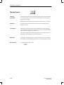
Communication
User’s Guide
Programmers
Provides information on connecting OPs to the following PLCs:
SIMATIC S5
SIMATIC S7
SIMATIC 500/505
block drivers for other PLCs
This document describes
the configuration and parameters required to
connect the OP to the PLC and to the network
the user data areas used for exchanging data
between the OP and the PLC
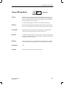
Other PLCs
Online Help
Programmers
Provides information for connecting OPs to PLCs
such as
Mitsubishi
Allen Bradley
Telemecanique
The drivers for connections to these PLCs are located
on separate floppy disks and are referred to as
NATIVE drivers. Installation of a driver also installs
the associated online Help.
ProTool User’s Guide
Release 09/96
iii
Preface
How the manual is
organized
The ProTool User’s Guide is organized as follows:
Chapters 1–4
contain general information. This is information about what
ProTool represents, what functions ProTool supports and
how ProTool is run under Windows.
Chapter 5
describes the basic approach to configuration with ProTool.
You should study this chapter before you start configuring.
Chapters 6–10 contain detailed information on how to configure different
objects. Instructions are given on step-by-step basis.
Chapters 11–17 show you how to
– create your configuration in different languages
– compile and download your configuration to the OP
– print your configuration
– copy and archive your configuration.
Conventions
Applicability
Obtaining
product support
iv
The following conventions are used in this manual:
VAR_23
Typewriting identifies inputs or outputs as shown on the
screen. They may be commands, filenames, entries in dialog boxes or system messages.
F1
Names of keys are shown in a different type for identification purposes.
File →
Edit
Menu items are shown in this form. The whole path is
always specified, showing how the menu item is accessed.
Variable
Dialog boxes as well as fields and buttons in dialog boxes
are shown in italic type.
The different issues of the User’s Guide apply to the following ProTool
versions:
Issue 07/94
Valid for ProTool versions up to and including 1.31.
Issue 09/95
Extensions and revisions.
Valid for ProTool version 2.0 or later.
Issue 09/96
Correction of errors and inclusion of the OP37.
Valid for ProTool version 2.5 or later.
In the event of technical queries, please get into touch with your point of contact at the Siemens agency or branch which takes care of your affairs. You
will find the addresses in Appendix D Siemens Worldwide. In addition, you
can call our hotline on +49 (911) 895-7000 (Fax 7001).
ProTool User’s Guide
Release 09/96
Preface
Abbreviations
The abbreviations used in the Protool User’s Guide have the following
meanings:
AG
AM
ANSI
AS 511
ASCII
EM
EM
LED
MPI
OLE
OP
PC
PG
PPI
PLC
RAM
UM
ProTool User’s Guide
Release 09/96
Automatisierungsgerät (German for ”PLC”)
Alarm Message
American National Standards Institute
Driver of the PU interface to the SIMATIC S5
American Standard Code for Information Interchange
Event Message
Equipment Manual
Light-Emitting Diode
Multipoint Interface (SIMATIC S7)
Object Linking and Embedding
Operator Panel
Personal Computer
Programming Unit
Point to Point Interface (SIMATIC S7)
Programmable Logic Controller
Random Access Memory (working memory)
User Manual
v
Preface
vi
ProTool User’s Guide
Release 09/96
Contents
1
Introduction . . . . . . . . . . . . . . . . . . . . . . . . . . . . . . . . . . . . . . . . . . . . . . . . . . . . . . . . . . . . .
1-1
2
Installation . . . . . . . . . . . . . . . . . . . . . . . . . . . . . . . . . . . . . . . . . . . . . . . . . . . . . . . . . . . . . .
2-1
3
Overview of Device-Specific Functions . . . . . . . . . . . . . . . . . . . . . . . . . . . . . . . . . . .
3-1
4
Working with ProTool . . . . . . . . . . . . . . . . . . . . . . . . . . . . . . . . . . . . . . . . . . . . . . . . . . . .
4-1
4.1
4.1.1
4.1.2
4.1.3
4.1.4
General Handling . . . . . . . . . . . . . . . . . . . . . . . . . . . . . . . . . . . . . . . . . . . . . . . .
Opening Several Configurations and Editors . . . . . . . . . . . . . . . . . . . . . . . . .
Using Online Help . . . . . . . . . . . . . . . . . . . . . . . . . . . . . . . . . . . . . . . . . . . . . . . .
Status Bar in ProTool . . . . . . . . . . . . . . . . . . . . . . . . . . . . . . . . . . . . . . . . . . . . .
All Menus . . . . . . . . . . . . . . . . . . . . . . . . . . . . . . . . . . . . . . . . . . . . . . . . . . . . . . .
4-1
4-3
4-4
4-6
4-6
4.2
Tool Bar . . . . . . . . . . . . . . . . . . . . . . . . . . . . . . . . . . . . . . . . . . . . . . . . . . . . . . . .
4-8
4.3
General Settings . . . . . . . . . . . . . . . . . . . . . . . . . . . . . . . . . . . . . . . . . . . . . . . . .
4-10
4.4
Information Functions . . . . . . . . . . . . . . . . . . . . . . . . . . . . . . . . . . . . . . . . . . . . .
4-11
4.5
Dialog Boxes . . . . . . . . . . . . . . . . . . . . . . . . . . . . . . . . . . . . . . . . . . . . . . . . . . . .
4-12
Configuring with ProTool . . . . . . . . . . . . . . . . . . . . . . . . . . . . . . . . . . . . . . . . . . . . . . . .
5-1
5.1
Procedure for Configuration . . . . . . . . . . . . . . . . . . . . . . . . . . . . . . . . . . . . . . .
5-2
5.2
Special Features of STEP 7 Integration . . . . . . . . . . . . . . . . . . . . . . . . . . . . .
5-6
5.3
The Most Important Objects and Their Settings . . . . . . . . . . . . . . . . . . . . . .
5-11
5.4
Partitioning the Display . . . . . . . . . . . . . . . . . . . . . . . . . . . . . . . . . . . . . . . . . . .
5-13
5.5
Editors . . . . . . . . . . . . . . . . . . . . . . . . . . . . . . . . . . . . . . . . . . . . . . . . . . . . . . . . . .
5-17
5.6
Copying to and from the Clipboard . . . . . . . . . . . . . . . . . . . . . . . . . . . . . . . . .
5-21
5.7
Assigning Function Keys . . . . . . . . . . . . . . . . . . . . . . . . . . . . . . . . . . . . . . . . . .
5-22
Variables . . . . . . . . . . . . . . . . . . . . . . . . . . . . . . . . . . . . . . . . . . . . . . . . . . . . . . . . . . . . . . . .
6-1
6.1
Using Variables to Perform Settings . . . . . . . . . . . . . . . . . . . . . . . . . . . . . . . .
6-5
6.2
Dependencies between Representation and Type of Variable . . . . . . . . . .
6-6
6.3
Dispalying Timers on the OP . . . . . . . . . . . . . . . . . . . . . . . . . . . . . . . . . . . . . .
6-9
6.4
Example of a Local Variable . . . . . . . . . . . . . . . . . . . . . . . . . . . . . . . . . . . . . . .
6-11
6.5
Using the STEP 7 Symbol Table . . . . . . . . . . . . . . . . . . . . . . . . . . . . . . . . . . .
6-12
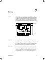
Screens . . . . . . . . . . . . . . . . . . . . . . . . . . . . . . . . . . . . . . . . . . . . . . . . . . . . . . . . . . . . . . . . .
7-1
7.1
7.1.1
7.1.2
7.1.3
7-5
7-5
7-6
7-7
5
6
7
Text, Character Graphic and Graphic . . . . . . . . . . . . . . . . . . . . . . . . . . . . . . .
Text . . . . . . . . . . . . . . . . . . . . . . . . . . . . . . . . . . . . . . . . . . . . . . . . . . . . . . . . . . . .
Character Graphic . . . . . . . . . . . . . . . . . . . . . . . . . . . . . . . . . . . . . . . . . . . . . . .
Graphics . . . . . . . . . . . . . . . . . . . . . . . . . . . . . . . . . . . . . . . . . . . . . . . . . . . . . . . .
ProTool User’s Guide
Release 09/96
i
Contents
7.2
7.2.1
7.2.2
Input and Output . . . . . . . . . . . . . . . . . . . . . . . . . . . . . . . . . . . . . . . . . . . . . . . . .
Input/Output Fields Containing a Symbolic Display . . . . . . . . . . . . . . . . . . .
Dynamic Attributes . . . . . . . . . . . . . . . . . . . . . . . . . . . . . . . . . . . . . . . . . . . . . . .
7-11
7-14
7-18
7.3
Bar graphs . . . . . . . . . . . . . . . . . . . . . . . . . . . . . . . . . . . . . . . . . . . . . . . . . . . . . .
7-20
7.4
7.4.1
7.4.2
Trend Graphics . . . . . . . . . . . . . . . . . . . . . . . . . . . . . . . . . . . . . . . . . . . . . . . . . .
Trends . . . . . . . . . . . . . . . . . . . . . . . . . . . . . . . . . . . . . . . . . . . . . . . . . . . . . . . . . .
Pattern Trends . . . . . . . . . . . . . . . . . . . . . . . . . . . . . . . . . . . . . . . . . . . . . . . . . . .
7-22
7-24
7-26
7.5
The Hide and Multiplex Options . . . . . . . . . . . . . . . . . . . . . . . . . . . . . . . . . . . .
7-30
7.6
Detecting a Called Screen on the PLC . . . . . . . . . . . . . . . . . . . . . . . . . . . . . .
7-34
Event Messages and Alarm Messages . . . . . . . . . . . . . . . . . . . . . . . . . . . . . . . . . . . .
8-1
8.1
Event Messages . . . . . . . . . . . . . . . . . . . . . . . . . . . . . . . . . . . . . . . . . . . . . . . . .
8-5
8.2
Alarm Messages . . . . . . . . . . . . . . . . . . . . . . . . . . . . . . . . . . . . . . . . . . . . . . . . .
8-7
9
Functions . . . . . . . . . . . . . . . . . . . . . . . . . . . . . . . . . . . . . . . . . . . . . . . . . . . . . . . . . . . . . . .
9-1
10
General Communication Areas . . . . . . . . . . . . . . . . . . . . . . . . . . . . . . . . . . . . . . . . . . .
10-1
10.1
10.1.1
10.1.2
Interface Area for Non-SIMATIC PLCs . . . . . . . . . . . . . . . . . . . . . . . . . . . . . .
Control and Acknowledgement Bits . . . . . . . . . . . . . . . . . . . . . . . . . . . . . . . . .
Data Areas in the Interface Area . . . . . . . . . . . . . . . . . . . . . . . . . . . . . . . . . . .
10-1
10-3
10-6
10.2
10.2.1
10.2.2
10.2.3
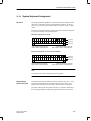
OP Keyboard and LED Assignments . . . . . . . . . . . . . . . . . . . . . . . . . . . . . . . 10-8
System Keyboard Assignment . . . . . . . . . . . . . . . . . . . . . . . . . . . . . . . . . . . . . 10-9
Function Keyboard Assignment . . . . . . . . . . . . . . . . . . . . . . . . . . . . . . . . . . . . 10-10
LED Assignment . . . . . . . . . . . . . . . . . . . . . . . . . . . . . . . . . . . . . . . . . . . . . . . . . 10-11
8
11
Configuring in Different Languages . . . . . . . . . . . . . . . . . . . . . . . . . . . . . . . . . . . . . . .
11-1
12
General Settings for the System . . . . . . . . . . . . . . . . . . . . . . . . . . . . . . . . . . . . . . . . . .
12-1
13
Compiling and Downloading a Configuration to the System . . . . . . . . . . . . . . . .
13-1
13.1
13.1.1
13.1.2
Downloading a Configuration to the OP . . . . . . . . . . . . . . . . . . . . . . . . . . . . .
Downloading a Configuration to the OP25, OP35 or the OP37 . . . . . . . . .
Downloading a Configuration to the OP45 . . . . . . . . . . . . . . . . . . . . . . . . . . .
13-2
13-2
13-4
13.2
Managing Configuration Data on the OP . . . . . . . . . . . . . . . . . . . . . . . . . . . .
13-5
13.3
Troubleshooting Download Problems . . . . . . . . . . . . . . . . . . . . . . . . . . . . . . .
13-8
14
Printing Your Configuration . . . . . . . . . . . . . . . . . . . . . . . . . . . . . . . . . . . . . . . . . . . . . .
14-1
15
Managing Your Configuration . . . . . . . . . . . . . . . . . . . . . . . . . . . . . . . . . . . . . . . . . . . .
15-1
15.1
File Structure . . . . . . . . . . . . . . . . . . . . . . . . . . . . . . . . . . . . . . . . . . . . . . . . . . . .
15-1
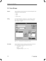
15.2
Project Manager . . . . . . . . . . . . . . . . . . . . . . . . . . . . . . . . . . . . . . . . . . . . . . . . .
15-6
Hints on Optimization . . . . . . . . . . . . . . . . . . . . . . . . . . . . . . . . . . . . . . . . . . . . . . . . . . . .
16-1
16.1
Polling time and update time . . . . . . . . . . . . . . . . . . . . . . . . . . . . . . . . . . . . . . .
16-1
16.2
Optimizing Loading and Saving Times . . . . . . . . . . . . . . . . . . . . . . . . . . . . . .
16-2
16
ii
ProTool User’s Guide
Release 09/96
Contents
A
Description of Functions . . . . . . . . . . . . . . . . . . . . . . . . . . . . . . . . . . . . . . . . . . . . . . . . .
A-1
B
PLC Jobs . . . . . . . . . . . . . . . . . . . . . . . . . . . . . . . . . . . . . . . . . . . . . . . . . . . . . . . . . . . . . . .
B-1
C
System Limits for OP25/35/37 . . . . . . . . . . . . . . . . . . . . . . . . . . . . . . . . . . . . . . . . . . . .
C-1
D
Siemens Worldwide . . . . . . . . . . . . . . . . . . . . . . . . . . . . . . . . . . . . . . . . . . . . . . . . . . . . .
D-1
I
Index . . . . . . . . . . . . . . . . . . . . . . . . . . . . . . . . . . . . . . . . . . . . . . . . . . . . . . . . . . . . . . . .
ProTool User’s Guide
Release 09/96
Index-1
iii
Contents
iv
ProTool User’s Guide
Release 09/96
Introduction
1
ProTool
is an easy-to-use configuration tool for Operator Panels (OPs). It can
run under Microsoft Windows. You can use a mouse or the keyboard to
execute most of the actions that have to be performed in .
Configuration
Configuration consists in creating screens and messages and linking them to
the PLC program. This means that the sequences of events on the PLC can be
visualized and manipulated.
Screens
Screens are used to create an image of the process. This means that the operator can quickly grasp the relationships and intervene in the process, should
this be necessary. Text explains individual elements on the screen. Graphics,
such as trends and bar graphs, display trend patterns – for example, of temperature or current fill levels. The operator has to call screens. He can also enter
values which are then transferred to the PLC.
Messages
Messages draw the operator’s attention to certain operating states or display
malfunctions in process execution. Messages are displayed automatically.
Keys
Operator Panels have a system keypad and a function keypad. The system
keypad contains the keys for operating the Operator Panel, such as cursor
control and inputs. Functions can be assigned to function keys in the configuration. By that the actual control sequence is implemented.
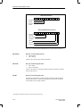
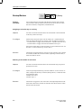
Configuration
data
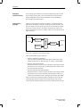
Configuration is performed on a PC or a programming unit (PU). The configuration then has to be compiled under ProTool and downloaded to the OP. If
connected to the PLC, the OP displays the current values. Figure 1-1 shows
the different phases in which work is performed with configuration data.
ProTool User’s Guide
Release 09/96
1-1
Introduction
ProTool
Configuration
data
Configuration
data
Connection
Figure 1-1
Configuration Phase, Download Phase and Process Control Phase
Components of
a configuration
A configuration consists of different components, including:
– setting the PLC and the type of connection
– general settings for the Operator Panel
– objects such as variables screens and messages.
Object types
ProTool incorporates different editors with which you can configure the different object types. Every object is created under a symbolic name, by which it
is referenced.
Printing a
configuration
Part or all of the configuration can be printed with ProTool. ”Part” means that
all the objects of a single object type, such as messages or variables, are printed.
1-2
ProTool User’s Guide
Release 09/96
2
Installation
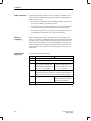
System
requirements
Table 2-1 shows the system requirements for running ProTool.
Table 2-1
System Requirements for ProTool
Device
Required
CPU
80486 SX/33 MHz
Main memory
8 MB
Free space on hard disk
2 MB in Windows directory
20 MB for ProTool
Graphics card
VGA
Floppy disk drive
3.5 ”
Microsoft Windows
MS Windows 3.1
MS Windows for Workgroups 3.11
Windows95
The system requirements depend on the operating system being used.
Virtual
memory
To improve performance, and thus speed, we recommend that you create virtual memory for Windows.
Virtual memory should be of the Permanent type and at least 8 MB. You
create virtual memory in the Windows main group under the Control Panel
program group. At this point you choose the 386 Enhanced icon.
Information is written temporarily from main memory to a file on your hard
disk. This file is a hidden file which reserves storage space on your hard disk.
When you require the information again, Windows loads it back into main
memory.
Methods of
installation
ProTool User’s Guide
Release 09/96
You have to install ProTool under Windows. You can install it either from the
floppy disks supplied to you or – for example, for networks – from your hard
disk.
2-1
Installation
STEP 7 integration
If STEP 7 programming software, version 2 or higher, is available on your
computer, you can install ProTool integrated in STEP 7. The advantages of
doing this are as follows:
S You manage ProTool projects with the SIMATIC Manager, the same tool
as you use for managing your STEP 7 projects.
S You can select STEP 7 symbols and data blocks from a text or graphic list
as variables. The data type and the address are entered automatically.
S ProTool lists all the PLCs in your STEP 7 project and determines the corresponding address parameters once a PLC has been selected.
Selecting
a language
Before installation proper begins, the system asks you what language and
options you wish to use. Installation begins in the same language as Windows
is installed. After you have selected the language in which you want to have
ProTool installed, installation is resumed in the language you specified. You
cannot change the ProTool language in Online mode. If you wish to be able
to use the ProTool user interface in a different language, you have to re-install ProTool.
Installing from
floppy disk
To install ProTool, proceed as follows:
Step
Windows95
1
Start Windows.
2
Insert the first floppy disk into the drive.
3
Select in the File Manager the
drive in which the floppy disk
is inserted and double-click on
the setup.exe program.
4
A dialog box appears in which you can click, under Options, the
software packages you wish to have installed. Perform modifications here only if you have ordered optional software packages.
5
Under STEP 7, select whether
ProTool should be installed as
Integrated or Standalone.
6
2-2
Windows 3.1 or later
Select in the Explorer the drive
in which the floppy disk is inserted and double-click on the
setup.exe program.
Follow the setup instructions on the screen.
ProTool User’s Guide
Release 09/96
Installation
Installable
components
You can vary the size of your installation by means of the options.
The following components are installed using the options offered to you:
ProTool
is the program for creating configurations.
Examples
are executable example configurations for both the OP and the PLC.
Graphics library
is ready-made symbols for different topics.
OP firmware
is the firmware for the OP. You have to specify this function when you are
installing ProTool for the first time.
Optional
PLC drivers
are drivers and examples for ”non-SIMATIC” PLCs and have to be ordered
separately.
Optional
functions
are loadable functions which you have to order separately.
Floppy disk for
OP45
For the OP45, you are supplied with a separate floppy disk labeled
CONFIGURATION-DISK COROS OP45, which you should install only on
the OP45. This floppy disk formats the hard disk of the OP45 and installs the
operating system for Operator Control and Process Monitoring.
Installing from
hard disk
For you to be able to install ProTool from hard disk, you have to copy the
floppy disks to your hard disk before you can start installing. When copying
to hard disk, abide by the conventions described below.
ProTool consists of four components, which are also labeled separately on
their floppy disks. These four components are:
– ProTool software
labeled ProTool
– Firmware
labeled Firmware
– Optional PLC drivers
labeled Driver
– Optional functions
labeled Functions
Create a separate directory for every one of the four components and the
floppy disks containing the name of the component and the number of the
floppy disk. The directories have to be created in accordance with the labels
on the floppy disks.
This means that you create for the ProTool software the directories
\PROTOOL\DISKn
where n is the number of the floppy disk. For floppy disk 1, you therefore
create a directory called \PROTOOL\DISK1; for floppy disk 2 you create a
directory called \PROTOOL\DISK2, and so on.
For the firmware, create a directory called \FIRMWARE\DISK1.
ProTool User’s Guide
Release 09/96
2-3
Installation
Icons in the
program group in
Windows 3.x
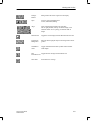
ProTool is installed in a program group of its own. Following installation,
you will see the following icons in the program group:
Double-clicking this icon launches ProTool.
For late breaking information about ProTool, double-click
this icon.
To call online Help, double-click this icon. You can also
call online Help in ProTool by pressing key F1.
To modify Setup, double-click this icon. You can modify
Setup to install, for example:
– a different language,
– an option or
– ProTool integrated or Standalone
The taskbar with
Windows95
With Windows95, you call ProTool by means of the taskbar. The icons described under Windows 3.x will be found here as entries on the taskbar.
If you have installed ProTool to be Standalone, you will find it in the Programs folder. If you have installed ProTool to be Integrated, you will find it
in the Simatic folder.
Note
Before you start work on a configuration, you should first read about the file
structure created for ProTool and the significance of the standard screens
supplied to you by consulting section 16.
2-4
ProTool User’s Guide
Release 09/96
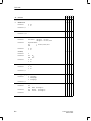
3
Overview of Device-Specific Functions
The following tables give you an overview of
S objects (table 3-1),
S settings for the target system (table 3-2) and
S general settings (table 3-3).
that can be configured for the individual devices. The tables refer to the parameters in the dialog boxes.
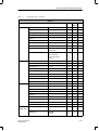
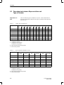
Table 3-1
Configurable Objects
Objects
Screens
OP25
OP35
OP37
OP45
Text
x
x
x
Character graphic
x
x
x
Graphic
x
x
x
Input
Display
Password level
Field length
Variable
Colors
Hide
Functions
Multiplexing
Information text
x
x
x
x
mono
x
x
x
x
x
x
x
x
x
x
x
x
x
x
x
x
x
x
x
x
x
x
Output
Display
Field length
Variable
Colors
Hide
Multiplexing
x
x
x
mono
x
x
x
x
x
x
x
x
x
x
x
x
x
x
Trend graphic
Actual Value
Samples/max.
Background color
Scale color
X axis
Y axis
Hide
Multiplexing
Trends
x
x
mono
mono
x
x
x
x
x
x
x
x
x
x
x
x
x
x
x
x
x
x
x
x
x
x
x
ProTool User’s Guide
Release 09/96
3-1
Overview of Device-Specific Functions
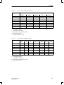
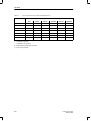
Table 3-1
Configurable Objects, continued
Objects
OP25 OP35 OP45
OP37
Bar
Direction
Scale color
Border
Y axis
Colors
Hide
Multiplexing
Variable
x
mono
x
x
mono
x
x
x
x
x
x
x
x
x
x
x
x
x
x
x
x
x
x
x
10/14
16/20
16/20
mono
x
x
x
x
x
x
x
x
x
x
x
x
x
x
Standby message
x
x
x
Information text
x
x
x
Function keys/soft keys
Attributes
Event
messages
Alarm
messages
3-2
Background color
Start screen
Information text
Functions
Hide
Message field
Display
Field length
Variable
Colors
Hide
Functions
x
x
x
x
x
x
x
x
x
x
x
x
x
x
x
x
x
x
Attributes
Priority
Port
Print
Relay
Functions
x
x
x
x
x
x
x
x
x
x
x
x
x
x
x
x
x
x
Information text
Message field
Display
Field length
Variable
Colors
Hide
Functions
x
x
x
x
x
x
x
x
x
x
x
x
x
x
x
x
x
x
Attributes
Priority
Acknowledgment
Port
Print
Relay
Functions
x
x
x
x
x
x
x
x
x
x
x
x
x
x
x
x
x
x
ProTool User’s Guide
Release 09/96
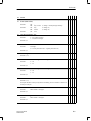
Overview of Device-Specific Functions
Table 3-1
Configurable Objects, continued
Objects
OP25 OP35 OP45
OP37
Variables
Recipes
Type
x
x
x
Length
x
x
x
Polling time
x
x
x
Decimals
x
x
x
Address
x
x
x
PLC
x
x
x
Limit values
x
x
x
Functions
x
x
x
Options
3 identifications max.
Initial value
x
x
x
x
x
x
Download
Write directly
Write indirectly
Read continuously
Online
x
x
x
x
x
x
x
x
x
x
x
x
Download
Direct/indirect
x
x
x
x
x
x
x
x
x
Name
x
x
x
Number
x
x
x
Version
x
x
x
x
x
x
Variable
x
x
x
Entry name
x
x
x
Display
x
x
x
Samples
x
x
x
mono
x
x
x
x
x
Variable
x
x
x
Line type
x
x
x
Limit values
x
x
x
Multiplexing
x
x
x
Guide lines
x
x
x
PLC
Identifications
Structure
Trends
3 max.
Fix/abolish
Colors
Trigger
Text or
graphic lists
Bit/pulse
Text list
Value/binary/bit
Text
x
x
x
x
x
x
Graphic list
Value/bit
Graphic
x
x
x
x
x
x
ProTool User’s Guide
Release 09/96
3-3
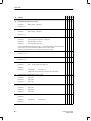
Overview of Device-Specific Functions
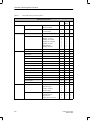
Table 3-2
Configurable settings for the target device
Settings for the system
Screen/Keys
PLC
Area pointer
Parameters
3-4
OP25
OP35
OP37
OP45
Window
Fixed window
Message indicator
x
x
x
x
x
x
Messages
Alarm messages
Event messages
x
x
x
x
x
x
x
x
x
System clock
Driver
SIMATIC S5–AS511
SIMATIC S5–FAP
SIMATIC S5–L2-DP
SIMATIC S7–300/400
SIMATIC S7–200
FREE SERIAL
SIMATIC 500/505
x
x
x
x
x
x
x
x
x
x
x
x
x
x
x
–
–
–
–
–
–
Parameters
Depend on PLC
x
x
x
Interface area
x
x
x
User version
x
x
x
Screen number
x
x
x
Data mailbox
x
x
x
Event messages
x
x
x
Alarm messages
x
x
x
Alarm acknowledgment PLC
x
x
x
Alarm acknowledgment OP
x
x
x
System key assignment
x
x
x
Function key assignment
x
x
x
LED assignment
x
x
x
Trend request
x
x
x
Trend transfer 1
x
x
x
Trend transfer 2
x
x
x
Messages
Printout
Alarm messages
Overflow warning
Character/Titles
x
x
x
x
x
x
x
x
x
x
x
x
Miscellaneous
User version
Time/date format
OP password
Recipe parameter record
x
x
x
x
x
x
x
x
x
x
x
x
ProTool User’s Guide
Release 09/96
Overview of Device-Specific Functions
Table 3-2
Configurable settings for the target device, continued
Settings for the system
OP25 OP35 OP45
OP37
Printer
Language
assignment
Interface
Interface
Type
Data bits
Parity
Stop bits
Baud rate
x
x
x
x
x
x
x
x
x
x
x
x
x
x
x
x
x
x
Settings
OP printer selection
Active OP printers
Setup
x
x
x
x
x
x
x
x
x
x
x
x
x
x
x
Attributes
x
x
x
Language dependent (3)
x
x
x
Language independent (1)
x
x
x
Entry points
x
x
–
Functions
x
x
–
OP25
OP35
OP37
OP45
x
x
–
Interface
x
x
x
Baud rate
x
x
x
LED image
x
x
x
Keyboard image
x
x
x
Password level
x
x
x
Functions
x
x
x
LED image
x
x
x
Keyboard image
x
x
x
Password level
x
x
x
Functions
x
x
x
Global assignment
x
x
x
Configuration possible in all
Windows languages
Languages simultaneously
loadable on the OP
Character set
Functions
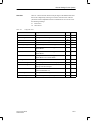
Table 3-3
3 configuration languages
Configurable General Settings
General settings
PC Interface
Function
K
Keys
Soft Keys
Download
ProTool User’s Guide
Release 09/96
MPI / serial
3-5
Overview of Device-Specific Functions
3-6
ProTool User’s Guide
Release 09/96
Working with ProTool
4
This chapter contains a general description of how to run ProTool. This description is not a substitute for the general Windows documentation.
4.1
General Handling
ProTool is primarily designed to be run with a mouse. The different editors
are provided with special tool bars that have editor-specific buttons. These
tool bars are shortcuts to frequently used functions.
ProTool can, however, be configured with the keyboard to a large extent.
The following sections tell you how to handle mice and keyboards.
Working with a
Mouse
In ProTool, you always use the left mouse button when you work with the
mouse. An exception to this is on selecting the background color, when you
use the right mouse button. Refer to online Help: Color palette.
In the ProTool documentation, the following terms are used for working with
a mouse:
Working without a
Mouse
Click
The mouse button is pressed and released.
Drag
The mouse button is pressed and held down, the cursor is
moved to its new position, and the mouse button is released.
Double-click
The mouse button is pressed twice in quick succession.
If you work without a mouse, the same key conventions apply in ProTool as
in Windows.
Table 4-1 shows the key combinations for fine adjustment of the fields on
screens.
ProTool User’s Guide
Release 09/96
4-1
Working with ProTool
Table 4-1
Keys and Key Combinations in ProTool
Keys/Key Combinations
Details of keys and
key combinations
Functions
Message editor:
SHIFT + left arrow
SHIFT + right arrow
CTRL + arrow
Select character to left of cursor
Select character to right of cursor
Next configured message
Character graphic field:
CTRL + arrow
Show line strokes
Move fields on screens:
Left arrow / right arrow
Up arrow / down arrow
Move field left/right
Move field up/down
Enlarge fields on screens:
CTRL + left arrow
CTRL + right arrow
CTRL + down arrow
CTRL + up arrow
Enlarge field horizontally to left
Enlarge field horizontally to right
Enlarge field vertically down
Enlarge field vertically up
Reduce fields on screens:
SHIFT + CTRL + left arrow
SHIFT + CTRL + right arrow
SHIFT + CTRL + down arrow
SHIFT + CTRL + up arrow
Reduce field horizontally to left
Reduce field horizontally to right
Reduce field vertically down
Reduce field vertically up
On some menus, the menu items are followed by details of keys and key
combinations. If you press that key or key combination, the menu item is
initiated. You do not have to chose the menu beforehand.
If menu items, icons or buttons are dimmed, the functions are unavailable.
4-2
ProTool User’s Guide
Release 09/96
Working with ProTool
4.1.1
Opening Several Configurations and Editors
Opening several
configurations
Under ProTool, you can open several configurations and editors simultaneously. You can copy data to and from a configuration via the Clipboard.
This simplifies work, since you do not have to re-configure all of the data.
Opening several
editors
The same applies to editors, for you can also open several editors simultaneously. You can also open an editor several times over, thus being able to
work at different points in the editor.
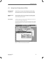
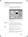
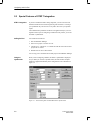
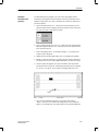
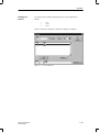
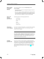
Active window
A window is opened every time you select a configuration or an editor. You
can open up to three projects simultaneously.
You can always edit the active window. You can recognize an active window
by the color of its title bar, which is different from that of the other windows
(refer to figure 4-1).
Figure 4-1
ProTool User’s Guide
Release 09/96
ProTool Screen with Several Open Windows
4-3
Working with ProTool
4.1.2
Using Online Help
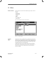
Purpose
Online Help is a complete reference tool which you can choose at any time
while you are configuring. By using online Help, you obtain information about dialog boxes, menus, ranges of values etc.
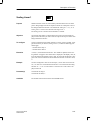
Calling
online Help
You can call online Help in several ways:
F1
You can always press F1 in ProTool to consult online Help.
Online Help is automatically called for the editor in which
you happen to be working or for the dialog box you selected.
Contextsensitive
Clicking the Help button on the tool bar transforms the
cursor into an arrow with a question mark. Clicking this
cursor in ProTool on an item about which you would like
more information calls online Help, and the corresponding
position in online Help is displayed.
The topics you click may be dialog boxes, menu items, buttons on the menu bar or palettes.
If you are not working with a mouse, you activate contextsensitive Help by pressing SHIFT + F1.
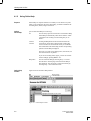
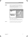
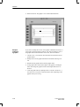
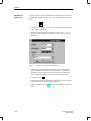
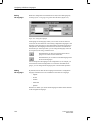
Help menu
Online Help
window
Figure 4-2 shows the online Help window:
Figure 4-2
4-4
You can call online Help by choosing Help → Contents
from the menu. The first page of ProTool online Help is
then displayed. You can specify a search term directly by
choosing Help → Search from the menu.
Online Help in ProTool
ProTool User’s Guide
Release 09/96
Working with ProTool
Green text
A green, underlined topic indicates a jump which links to another topic. If
you click on the jump, the new topic is displayed in a different window.
A green, dotted underlined topic indicates a jump which references a brief
explanation. Clicking the cursor on this jump displays a window containing
the explanation. The window is hidden by clicking anywhere on its surface.
Jumps in
screen dumps
Furthermore, online Help frequently displays screen dumps of ProTool, i.e.
editors, dialog boxes etc. There are jumps under many of these screen dumps.
If you point to a jump, the pointer changes to a hand shape. If you click on
the jump, you go to other topics or call a secondary window. You obtain further information in this superimposed window.
If you click in online Help on a button or a menu item in a screen dump
which causes the ProTool software to branch to a dialog box, online Help
similarly branches to the related topic. If you click in online Help on a field
in which an entry has to be made in the ProTool software, a secondary window containing a description is opened.
Displaying
jumps
ProTool User’s Guide
Release 09/96
To make the jumps in screen dumps visible, press the following key combinations:
CTRL + TAB
All invisible jumps are displayed while you hold down
CTRL + TAB.
TAB
The first invisible jump is displayed. Every time you press
TAB thereafter, the next jump is displayed. Press RETURN
to initiate the jump.
SHIFT + TAB
This key combination displays the previous jump. Press
RETURN to initiate the jump.
4-5
Working with ProTool
4.1.3
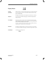
Status Bar in ProTool
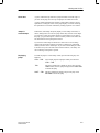
Purpose
The status bar is the bar at the bottom of the screen. In ProTool, the status bar
displays general information and editor-specific details.
The general information includes items such as the OP that you have selected
or how you can call online Help. Editor-specific details, on the other hand,
might be the language and the assignment of the message in the area pointer.
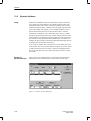
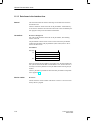
Figure 4-3 shows the status bar with messages.
Figure 4-3
Displaying
information
4.1.4
In the status bar you can also display information about the functions of
jumps and menu items. To do so, click the topic you require and hold down
the mouse button. While you do this, the corresponding information will be
displayed in the status bar. If you do not want to initiate the function, continue to hold down the mouse button and drag the mouse away from the selected topic.
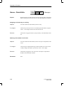
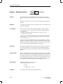
All Menus
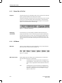
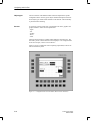
Menu bar
There are various editing levels with configuration. They are represented by
main menu items on the menu bar (see figure 4-4).
Figure 4-4
Main menu items
4-6
Status Bar with Messages
Menu Bar
All the editing steps of an editing level are arranged under one main menu
item. The main menu items are specifically:
File
All editing actions concerning the entire configuration are
concentrated here. At this point you can, for example, open
and save files, compile files and download them to the OP
etc.
Edit
All editing actions concerning selected or highlighted sections of the configuration are concentrated under this main
menu item. At this point you can, for example, cut, copy,
paste etc. fields or text.
ProTool User’s Guide
Release 09/96
Working with ProTool
Editor-dependent
menu items
Editors!
The Editors window is displayed. All the editors used for
configuring the OP are concentrated here. At this point you
can select the editor you want to work with – for example,
for screens, event messages etc.
System
General settings for the OP are listed under this main menu
item. At this point you define the structure of the display,
the link to the PLC program and PLC-specific settings.
Options
At this point you will find default settings, cross-references
and OLE settings.
Window
All the editing steps for arranging the windows of ProTool
are located here. You can select, for example, the window
you want to have on top, or you can arrange all the open
windows on the screen, etc.
Help
By choosing Help, you go to online Help.
Editor-dependent menu items appear only after the corresponding editor has
been called. All the editing steps specific to that editor appear under these
menu items. The following menu items are affected:
Screen
At this point you can, for example, select screen attributes,
create fields, display palettes etc.
Messages
By choosing messages, you can, for example, edit variables
or information text, open additional windows etc.
Cross-reference You obtain information about which objects refer to each
other in your configuration.
ProTool User’s Guide
Release 09/96
4-7
Working with ProTool
4.2
Tool Bar
Purpose
Some functions can be accessed via the menu system and also directly by
means of the tool bar at the top border of the screen. The buttons are selfexplanatory and represent shortcuts.
The tool bar always features the functions belonging to a specific editor. The
structures of the tool bar for the screen editor and the message editor are
shown in figures 4-5 and 4-6.
Summary
of functions
4-8
Figure 4-5
Tool Bar for Screen Editor
Figure 4-6
Tool Bar for Message Editor
Below, a description is given of all the buttons on tool bars:
New
Open a new project with the default settings.
Open
Open an existing project. The File Open dialog box is
opened. You choose the project you require from the dialog
box.
Save
Save a project under its name. If it is a new, unnamed project, the Save as dialog box is opened.
Cut
Cut highlighted sections from a project and store them on
the Clipboard.
Copy
Copy highlighted fields from the project and store them on
the Clipboard.
Paste
Paste fields in the project from the Clipboard.
Contextsensitive help
Obtain a special cursor. Click the cursor on the item
about which you require more information. Online help is
chosen.
ProTool User’s Guide
Release 09/96
Working with ProTool
Enlarge/
Reduce
Enlarge/reduce the screen segment on the display.
Style
Assign a style to highlighted text:
inverse, underlined, flashing.
Align
Align selected fields in relation to each other:
left- or right-justified, from top or bottom margin, with
identical column or row spacing, of identical width or
height.
Monochrome
Toggle the screen display between Monochrome and Color.
Foreground/
Background
Place the selected graphic object in the foreground or background.
WYSIWYG
mode
Toggle variables between their symbolic name and their
actual length.
Edit
Toggle between message and information text.
information text
Insert field
ProTool User’s Guide
Release 09/96
Insert fields in a message.
4-9
Working with ProTool
4.3
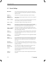
General Settings
Menu items
You can customize the ProTool user interface. This includes arranging the
windows and displaying or hiding palettes. Specifically, the following menu
items are involved:
Options →
Default Setting
Options →
OLE Preferences
At this point you can modify the default settings of names and settings.
Screen → Surface
At this point you can set how the surface should be displayed on your screen.
That is, whether you prefer a grid, with dots or without dots.
Screen → Zoom
At this point you enlarge or reduce the image on the screen.
Screen →
Tool Palette
At this point you can display or hide the tool palette for the screen editor.
When displayed, the tool palette is used for quick configuration of fields. You
do not have to choose Screen → Fields from the drop-down menu.
Screen → Character
Graphics Palette
At this point you can display or hide the character graphics palette for the
screen editor. The character graphics palette is displayed only if you are creating a field with graphics characters.
Screen →
Size/Position
If you choose Size/Position, a window is displayed or hid. It contains details
of the current cursor position and the size of the object you selected. Values
are specified in pixels.
Screen →
Black/White
In an OP25 configuration, the image on the screen is toggled between Black/
White and Color.
Screen →
Reference Text
If you select Reference Text, the screen in the reference language corresponding to the active screen is displayed. If you choose the Apply button on the
reference screen, all text strings on the reference screen are applied to the
active screen.
Messages →
Attribute Window
You use this menu item to display or hide the attribute window. In this window, you set different options which apply to just one message. This might be
its priority, for instance.
Messages →
Reference Text
You use this window to display or hide the reference text window. In this
window, message text is displayed in the reference language.
Window
Under this menu item, you will find settings for customizing your screen.
This includes displaying more than one window on your screen simultaneously, for instance.
Window →
Keyboard
You use this menu item to display or hide the language-dependent keyboard
assignment.
4-10
At this point you select the programs which you wish to use for creating and
editing graphics.
ProTool User’s Guide
Release 09/96
Working with ProTool
4.4
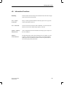
Information Functions
Summary
ProTool contains functions that provide information about the entire configuration. These items are listed below:
File → Project
Information
Here you will find general information about the project: device type, date
created and modified, author etc.
File → Download
Once the connection to the OP has been established, you can learn here the
firmware version and available storage capacity on the OP.
System → Memory
Requirements
After a configuration has been downloaded, the storage space it requires on
the OP is displayed.
Options →
Cross-reference
The objects that refer to each other are displayed. If, for example, you wish
to delete a variable which is being used in a field, you find the associated
field by means of Cross-Reference. Double-click on the specified field to
have ProTool jump directly to the field.
ProTool User’s Guide
Release 09/96
4-11
Working with ProTool
4.5
Dialog Boxes
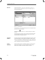
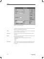
Settings
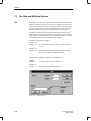
When you open a dialog box, only the essential settings are visible initially.
Optional settings may be accessed by clicking a button. Clicking a button
opens yet another dialog box, which may contain more buttons.
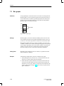
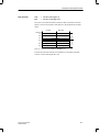
An example of the structure of a dialog box is shown in figure 4-7.
Figure 4-7
Bar Dialog Box
A description is given below of all the points that you have to remember
when you are using dialog boxes.
Branching to other
dialog boxes
If there is an ellipsis after an option in a dialog box (see figure 4-7: Edit),
ProTool branches to another dialog box if you choose the button.
If there is a check box in front of an option in a dialog box, you branch to an
optional setting (see, for example, figure 4-7: Y axis) by choosing the button.
You can tell from the check box whether a configuration is present in the dialog box (checked box) or not (unchecked box).
Closing a
dialog box
Dialog boxes contain either OK and Cancel buttons or a Close button.
In the first case, you have two options for closing a dialog box – you can
close with or without saving.
To close a dialog box and to save any changes you may have made at the
same time, exit from the dialog box by pressing the OK button.
If you exit from the dialog box by pressing the Cancel button, any changes
you may have made are lost.
In the second case, the Close button is used to close the dialog box. In this
type of dialog box, any changes you may have made take immediate effect;
in other words, changes do not have to be explicitly saved.
4-12
ProTool User’s Guide
Release 09/96
Configuring with ProTool
Device type
5
You configure the different OPs in basically the same manner. Before you
can start work on your configuration, you have to set the device type – for
example, OP25. You are now offered only the functions that are available
with this device type. You cannot modify the device type for this configuration once it has been set.
You can use configurations created for the OP35 on the OP37. By choosing
File → Convert from the menu, you can convert a configuration created for
an OP35 into a configuration for an OP37.
Display
The display on the Operator Panel can be customized. This refers to the location and size of the different windows in which screens and messages are
displayed. The display format applies to the whole configuration. ProTool
exhibits a default setting.
Object types
The items you configure are individual objects. We distinguish between different types of objects, such as messages, screens, variables etc. A separate
editor is available for every type of object.
Variables
The link to the PLC is established by means of variables. Variables are used
on screens and in messages to read values from the PLC and to display them
on the OP. Similarly, variables can be used to write values to the PLC.
Information text
Information text can be configured to provide the OP operator with additional
information about inputs and messages.
General settings
General settings for the system and the communication areas in the PLC have
to be performed centrally.
Compiling,
downloading
Upon completion, the configuration has to be downloaded to the OP. In this
procedure the configuration is first compiled. ”Compile” means that an OPreadable file is created. This file is then downloaded to the OP.
ProTool User’s Guide
Release 09/96
5-1
Configuring with ProTool
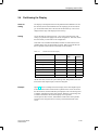
5.1
Procedure for Configuration
Introduction
A configuration has to be created step by step. Certain steps are mandatory,
others are optional.
An explanation is provided in the following of the different configuration
steps in the order in which they have to be performed. This followed by a list
of the settings required for configuring different functions.
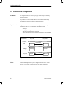
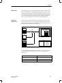
Required details
Figure 5-1 shows the basic details that have to be provided for the Operator
Panel and the PLC in your configuration. These details include
–
–
–
–
–
OP type
display partitioning
PLC to which the OP will be connected
driver which the PLC and OP will use to communicate with each other
communication areas.
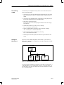
Configuration:
Hardware
and
driver
General
settings
Visualization
of process
Figure 5-1
Objects
5-2
OP-specific
components
PLC-specific
components
Communication
OP type
Display
partitioning
Objects
PLC
Communication
data areas
Addresses
Basic Structure of a Configuration
The actual visualization of a process is performed by using objects, such as
screens and messages. These objects are supplied with current values from
the PLC. The specific values concerned are set by means of addresses.
ProTool User’s Guide
Release 09/96
Configuring with ProTool
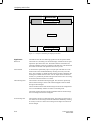
Procedure
You create your configuration on a PC or a PU and then download it to the
OP. The procedure for configuration is specifically as follows:
1. Set device type
After a new configuration has been opened, the Device Selection dialog
box appears. At this point you set the device type – for example, OP35.
The other items displayed by ProTool thereafter are device-specific.
2. Set display partitioning
You set the partitioning of the display by choosing the menu command
System → Screen/Keys. The Screen/Keys dialog box is opened. The settings you perform here apply to the whole configuration. There is a default setting. Check whether the default setting applies to your configuration. If not, modify the default setting to meet your requirements.
3. Set PLC and communication driver
You must specify in the configuration the PLC to which the OP will be
connected and the driver which the PLC and OP will use to communicate
with each other. This is done by choosing the menu command System →
PLC. The PLC dialog box is displayed. All the settings you perform here
are saved under a symbolic name. If you use a variable in an object, you
specify this symbolic name to connect the OP to the PLC.
4. Enter communication areas (area pointers)
For the OP and the PLC to be able to communicate with each other, you
must define common data areas. These data areas are known as communication areas. You enter them by choosing System → Area Pointers from
the menu. The communication areas you enter will depend on the types of
object that are being configured. Table 13-1 shows the dependencies.
For the SIMATIC S5 PLC, you must create the interface area by choosing
Area Pointers. A detailed description of the interface area will be found in
the Communication User’s Guide.
5. Configure objects
Now configure messages, screens and recipes, depending on the requirements of your process.
Variables enabling the link to the PLC can be created either directly using
the Variables editor or you have to wait until you configure the different
objects. If, for example, you create an input field on a screen, you can call
the dialog box for creating variables by choosing the Edit button.
ProTool User’s Guide
Release 09/96
5-3
Configuring with ProTool
6. Compile configuration
For the configuration to run on the OP, it must be first compiled. To do
this, choose File → Compile from the menu in ProTool
During compilation, a check is made for inconsistencies in the configuration. One inconsistency might be, for example, that a particular type of
object has been configured without the corresponding communication
area being created.
7. Download configuration to OP
You download the configuration to the OP by choosing File → Download
from the menu. Should there be a current, compiled version already, it is
downloaded. If a compiled version does not exist, the configuration is
first compiled and then downloaded.
Example for
SIMATIC S5
To create a configuration for an OP35, proceed as follows:
1. Call ProTool, open the file S5_35.pdb from the directory
called protool\standard and save it choosing a new file name.
2. Choose System → PLC from the menu to set the PLC.
3. Press the Edit button. The Driver dialog box now appears. We want to
establish the connection using the SIMATIC AS511 driver.
4. Press the Parameters button. The SIMATIC S5-AS511 dialog box is now
displayed.
5. Select in the SIMATIC S5-AS511 dialog box, for example, the CPU Type
S5 115U CPU944 if you wish to connect the OP35 to that PLC.
6. If you close the dialog box by clicking OK, the settings are applied. Do
exactly the same in all the other dialog boxes which you may have opened. Exit from the PLC dialog box by clicking the Close button in order
to apply all the settings.
7. Choose System → Area Pointers from the menu to configure the interface
area, DB-TDOP.
8. In the Type field, you will see that Interface Area has already been selected. Press the Add button. A dialog box having the title Interface Area is
opened.
9. Enter the following values in the Interface Area dialog box:
DB: 51, Length: 255. This means that DB51 is the interface area.
10. Exit from the Interface Area dialog box by pressing OK in order to apply
the settings.
5-4
ProTool User’s Guide
Release 09/96
Configuring with ProTool
11. Then partition the OP display by choosing System→ Screen/Keys from the
menu.
12. Select for Alarm/Event Mess. the setting Window/Window, to enable both
event messages and alarm messages to be displayed on screens simultaneously.
13. Via Active, select the Message Area and, holding down the mouse button,
position it in the screen layout. This concludes partitioning of the OP display.
14. Configure a screen (refer to section 7).
15. Choose File → Save from the menu to save the file.
16. Choose File → Compile from the menu to compile the configuration.
17. Connect the OP to your PC or PU. Choose File → Download from the
menu to download the configuration to the OP.
ProTool User’s Guide
Release 09/96
5-5
Configuring with ProTool
5.2
Special Features of STEP 7 Integration
STEP 7 Integration
If you have installed ProTool as being integrated, you can access the same
database with ProTool as with the engineering tools of STEP 7. You assign
your symbolism only once and use it everywhere. This saves you repeated
inputs.
The communication parameters of the PLC are applied directly to your configuration. When you are configuring variables and area pointers, you access
the STEP 7 symbol table.
ProTool
You call ProTool as follows:
1. Start the SIMATIC Manager.
2. Select an S7 project or create a new one.
3. Choose Insert → Hardware → COROS OP from the menu. The ProTool
project OP1 is created.
4. Double-click on OP1 to start ProTool.
You can copy, move and delete the ProTool project in the SIMATIC Manager.
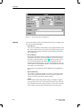
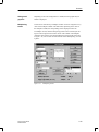
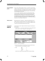
Using the
symbol table
When you are configuring variables, the STEP 7 symbol table is displayed
for you. When you click on a symbolic name, the name and the complete
address are applied automatically to the configuration. This is illustrated in
figure 5-2.
Figure 5-2
5-6
Variable Dialog Box with Embedded STEP 7 Symbol Table
ProTool User’s Guide
Release 09/96
Configuring with ProTool
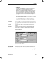
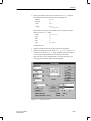
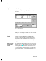
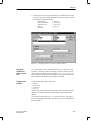
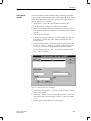
Selecting
the PLC
Select the PLC in the way you normally would. For the parameters, the
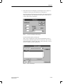
SIMATIC S7 - 300/400 dialog box (refer to figure 5-3) displays all the networks, CPUs and FMs available in the STEP 7 project. Once you have selected the network and the CPU by means of symbolic names, the parameters
and addresses are entered for you automatically.
You can select the CPU symbolically only if you have placed it in an S7 station using the SIMATIC Manager, assigned parameters to it and networked it.
Figure 5-3
SIMATIC S7 – 300/400 Dialog Box
If you have not yet created the STEP 7 configuration, you can type in the
parameters. To type in the parameters, select Define the parameters yourself.
Updating
ProTool User’s Guide
Release 09/96
The symbol table and the address parameters are continuously updated via
the symbolic link. STEP 7 modifications are applied immediately.
5-7
Configuring with ProTool
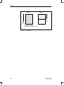
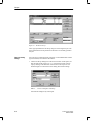
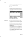
Menu File
Choose menu items File → New, File → Open and File → Save As... in
ProTool to open STEP 7 dialog boxes. By way of an example, figure 5-4
shows the Open dialog box.
Figure 5-4
Open Dialog Box
In this dialog box, you can open ProTool projects. You can recognize ProTool
projects by the icon preceding them
.
The dialog boxes for New and Save As... look alike, but they have different
functions.
On opening, specify in the Object Name entry field an existing ProTool project. When creating a new project, you can enter at this point a new name
having a length not exceeding 24 characters.
Integrating
projects
You cannot call projects under the SIMATIC Manager that have been created
as stand-alone projects. For these projects to be linked to a STEP 7 project,
they have to be integrated. To integrate these projects, choose in ProTool File
→ Integrate from the menu. Give the ProTool project a different name in the
STEP 7 configuration from that in the original project.
ProTool
Standalone
ProTool can still be started as a stand-alone program if you call ProTool Setup and choose Standalone. If you wish to modify this setting in Setup,
ProTool is not re-installed, only the link to STEP 7 is canceled.
5-8
ProTool User’s Guide
Release 09/96
Configuring with ProTool
Example:
Creating a
project
In this example, you will create a ProTool project, including all the preliminary work for connecting the OP to the S7 PLC.
1. Create a new STEP 7 project called GETSTART in the SIMATIC Manager.
2. Select the GETSTART project. Then choose Insert → Hardware →
SIMATIC 300-Station from the menu. The SIMATIC 300-Station1 icon
appears in the SIMATIC Manager.
3. If, when you are creating the GETSTART STEP 7 project, the icon for an
MPI network does not appear, choose Insert → Subnet → MPI Network.
4. Select the SIMATIC 300-Station1 icon and choose Edit → Open Object
from the menu. The Hardware Configuration dialog box appears.
5. Open the hardware catalog by choosing View → Catalog from the menu.
6. Click in the hardware catalog on the + sign preceding SIMATIC 300, then
on the + sign preceding RACK 300. Select Mounting Rail and drag it to
the empty, blue bar of the Hardware Configuration dialog box. The first
line (expansion slot 0) of the configuration table appears; the rail is entered on it.
7. Click on the + sign preceding expansion slot 0 to open the configuration
table completely.
8. Click in the hardware catalog on the + sign preceding CPU-300. Select
CPU314 and drag it to expansion slot 2 of the configuration table. The
CPU314 is entered in expansion slot 2, and the line remains selected.
9. Choose Edit → Object Properties. The Properties – CPU 314 dialog box
appears.
10. Click the MPI button on the Properties card. The Properties – MPI Node
dialog box is opened.
11. Enable the Networked list box by clicking it. Select the MPI Network 1
entry beneath it.
12. Then, close all the dialog boxes by clicking OK or by saving. In this way
you have created and networked the PLC to the extent required for ProTool. The blank STEP 7 symbol table has been created automatically.
13. To open it, click first on the + sign preceding the GETSTART project, on
the + sign preceding SIMATIC 300 Station1, on the + sign preceding
CPU314 and on the + sign preceding S7 Program1. Select Symbol table
SY and then choose Edit → Open Object. The symbol table is opened.
14. Make the following entries:
Symbol:
Mixer1
Address:
I0.1
The BOOL data type is entered automatically.
15. Save and then close the symbol table. You can use the Mixer1 symbol
later to configure a variable.
16. Open the ProTool project containing the standard configurations which
were supplied to you. Copy object OP25 – S7 to your GETSTART project.
ProTool User’s Guide
Release 09/96
5-9
Configuring with ProTool
17. Double-click on the Copy OP25 – S7 icon. ProTool is started, and the
standard configuration for OP25 is opened.
18. Choose System → PLC from the menu. The PLC dialog box is opened.
By default, the SIMATIC S7–300/400 PLC is entered at this point in the
case of STEP 7 integration.
19. Now, first click the Edit button and then the Parameters button. The
SIMATIC S7 300/400 dialog box appears.
20. Select the entry MPI Network1 in the Connect OP to Network list box.
This entry now appears in the Select Communicating Peer list box.
21. Click in the Select Communicating Peer list box on the + sign preceding
the MPI Network1 entry. The entry CPU314 (S7 Program1) appears.
22. Select the CPU314 (S7 Program1) entry and close all the dialog boxes
dealing with the PLC by clicking OK or Close. The connection between
the OP and the PLC is thus established.
23. Double-click in the editor window on Variable. The Variable dialog box
appears.
24. In the PLC list box, choose PLC_1. In the Symbol list box, you will now
see the Mixer1 symbol from the STEP 7 symbol table. Double-click this
symbol. The following values are applied to the dialog box:
Mixer 1 in the Name entry field
BOOL in the Type list box
I in the Area list box
0 in the E entry field
1 in the Bit entry field
5-10
ProTool User’s Guide
Release 09/96
Configuring with ProTool
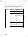
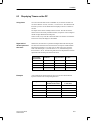
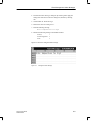
5.3
The Most Important Objects and Their Settings
When you configure an object type – for example, messages – more settings have to be performed in
ProTool. These details refer to communication, the method of presentation on the display, and printout.
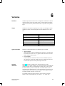
Table 5-1 lists the most important types of object and the settings required for them.
Table 5-1
Objects Used and the Necessary Settings
Objects Used
Associated Settings
Menu Item or Dialog Box
PLC
PLC type, driver
System → PLC
Interface Area
(SIMATIC S5 only)
System → Area Pointers
Event message area
System → Area Pointers
Event message area or
message line
System → Screen/Keys
Message printout
Messages → Attribute Window
System → Parameters → Messages
Message buffer
System → Parameters → Messages
Call event message area
and event message buffer
using function keys:
– local
– global
Screen
System → Screen/Keys
– Text
– Output
Edit text
Variable
Messages → Edit/Insert Field
Alarm messages
Alarm message area
System → Area Pointers
Acknowledgment area
System → Area Pointers
Alarm message area or
message line
System → Screen/Keys
Message indicator
System → Screen/Keys
Message printout
Messages → Attribute Window
System → Parameters → Messages
Message buffer
System → Parameters → Messages
Edit text
Variable
Messages → Edit/Insert Field
Event messages
– Text
– Output
ProTool User’s Guide
Release 09/96
5-11
Configuring with ProTool
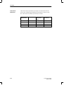
Table 5-1
Objects Used and the Necessary Settings, continued
Objects Used
Associated Settings
Menu Item or Dialog Box
– Text
– Input and output
– Dynamic input/output
– Trend graphic
– Bar graph
– Graphic character
– Bitmap
Edit text
Variable
Variable and text or graphic list
Trends and variables
Variable
–
–
Screen → Fields → Text
Screen → Fields → Input/Output
Screen → Fields → Text or Graphic List
Screen → Fields → Trend Graphic
Screen → Fields → Bar
Screen → Fields → Character Graphic
Screen → Fields → Graphic
Call screen
Assign function key
– local
– global
Screens
System → Screen/Keys
Screens
Screen → Fields → Trend Graphic
Trends
– Trends
Time-triggered:
variable
Bit-triggered:
variable
trend request
trend transfer 1
System → Area Pointers
– Trend patterns
Variable
Trend request
Trend transfer 1
Trend transfer 2 (for configured
switch buffer only)
Recipes
Variables
Data mailbox
System → Area Pointers
Place standard screens for
”Create Data
Records” on function keys:
– local
– global
Screens
System → Screen/Keys
5-12
System → Area Pointers
ProTool User’s Guide
Release 09/96
Configuring with ProTool
5.4
Partitioning the Display
Areas for
setting
The display on the Operator Panel can be partitioned into different areas. On
the one hand, there are the different areas for displaying screens and messages. On the other hand, there is the area for the function keys. Icons can be
displayed at the edge of the display for the soft keys.
Setting
You set the areas by choosing System → Screen/Keys from the menu. The
settings you perform here apply to the whole configuration. Therefore, define
the areas before you start work on the configuration.
Some areas can be enabled and disabled, and their size and location can be
modified. Many areas are permanently assigned. Table 5-2 lists all the areas
that are possible and the extent to which they can be modified.
Table 5-2
Settable Areas for the Display
Area
Enable/Disable
Modify
Size
Location
Basic area
No
No
No
Fixed window
Yes
Yes
No
Event message area
Yes
No
Yes
Alarm message area
Yes
No
No
Message line
Yes
Yes
Yes
Message indicator
Yes
No
Yes
Icons (individual)
Yes
No
No
All the other areas, such as the system message area, Help window, date and
time window and setpoint inputs, cannot be configured.
Example
ProTool User’s Guide
Release 09/96
Figure 5-5 shows an example of how the display on the OP25 might be partitioned. The fixed window located at the top border of the screen can contain
the date and time, which should always be displayed. The event message area
is partially superimposed on the fixed window. When the event message area
is called on the OP, the date and time display is less important.
Current process data, however, should still be visible to the extent possible.
Icons have been assigned to the six soft keys on the bottom border of the
screen.
5-13
Configuring with ProTool
ÉÉÉÉÉÉÉÉÉÉÉÉÉÉÉÉÉÉÉÉÉÉ
ÉÉÉÉÉÉÉÉÉÉÉÉÉÉÉÉÉÉÉÉÉÉ
ÈÈÈÈÈÈÈÈÈÈÈÈÈÈÈÈÈÈÈÈ
ÉÉÉÉÉÉÉÉÉÉÉÉÉÉÉÉÉÉÉÉÉÉ
ÈÈÈÈÈÈÈÈÈÈÈÈÈÈÈÈÈÈÈÈ
ÉÉÉÉÉÉÉÉÉÉÉÉÉÉÉÉÉÉÉÉÉÉ
ÈÈÈÈÈÈÈÈÈÈÈÈÈÈÈÈÈÈÈÈ
ÉÉÉÉ
ÊÊÊÊ
ËËËËË
ÇÇÇÇ
ÉÉÉÉ
ÊÊÊÊ
ËËËËË
ÇÇÇÇ
ÉÉÉÉ
ÊÊÊÊ
ËËËËË
ÇÇÇÇ
Figure 5-5
Example of Partitioning the Display on the OP25
Significance
The different areas have the following significance for the Operator Panel:
Basic area
The lowest level, extending over the whole display. All other areas are superimposed on parts of the basic area. The location and size of the basic area
cannot be modified. Screens are configured in the basic area. This means that
the contents of the basic area depends on the screen you call.
Fixed window
A window that is permanently open. It occupies part of the basic area. The
fixed window can be enabled/disabled by choosing Screen/Keys from the
menu. If it is enabled, it is displayed while screens are being configured, thus
reducing the available area for screens. You can adjust the size of the fixed
window; it is permanently located at the top border of the screen. You configure the fixed window with the screen editor.
Alarm message area
The window in which alarm messages appear. The window is opened only
when an alarm message is issued. The window disappears when the alarm
message is acknowledged.
The size and the location of the alarm message area cannot be configured. Its
size is set automatically with the size of the event message area.
The display of alarm messages cannot be disabled. Either an alarm message
area or a message line has to be configured.
Event message area
5-14
The window in which event messages appear. The window is opened only if
it is called. The event message area can be enabled and disabled by choosing
Screen/Keys. There is a choice of two settings for its height. Its location can
also be changed.
ProTool User’s Guide
Release 09/96
Configuring with ProTool
Message line
The area in which alarm messages and event messages are displayed. The
message line can be enabled and disabled by choosing Screen/Keys. However, you cannot set the message line and the event message area.
The dependencies between the message area and the line are listed in table
5-3. There is a choice of two settings for the height of the message line. Its
location can also be changed.
Message indicator
A symbol which draws your attention to waiting alarm messages. The message indicator can be enabled and disabled by choosing Screen/Keys. Its size
cannot be modified, but you can change its location.
Dynamic position
With the OP35 and OP37, the message and information text windows are
positioned dynamically as a function of the cursor position so that inputs undergoing editing are not concealed. This function can be enabled and disabled by choosing System → Screen/Keys.
Icon
An icon can be placed on the display for the soft keys. This is possible only
for the Fx keys that are directly arranged around the screen. You can assign
every key separately. An assignment applies globally. The icons appear on
every configured screen. The assignment and the icon for every screen can be
modified later. The modification then applies only locally.
Dependencies
There are dependencies between the display options for alarm messages and
event messages. Table 5-3 lists those dependencies.
Table 5-3
ProTool User’s Guide
Release 09/96
Possible Settings for Event Messages and Alarm Messages
Display of Alarm messages
Display of Event Messages
Window
Window
Window
Line
Window
Off
Line
Line
5-15
Configuring with ProTool
Priorities
The areas have different priorities. This is noticeable when the areas are
cascaded. The high-priority area is superimposed on the low-priority area.
Table 5-4 contains a matrix which tells you which areas are superimposed
when cascading is effective.
Table 5-4
Priorities of the Areas when Cascading is Effective
Area
Superimposed
Basic
area
5-16
Fixed
window
EM
area
AM
area
Message Message
line
indicator
Softkeys
Basic
area
–
–
–
–
–
–
–
Fixed
window
x
–
–
–
–
–
–
EM
area
x
x
–
–
–
–
x
AM
area
x
x
x
–
–
–
x
Message
line
x
x
–
–
–
–
x
Message
indicator
x
x
x
–
x
–
x
Softkeys
x
x
–
–
–
–
–
ProTool User’s Guide
Release 09/96
Configuring with ProTool
5.5
Editors
Editors in ProTool
ProTool provides various editors for the different types of object. There are
editors for:
– screens
– event messages
– alarm messages
– variables
– recipes
– trends
– text or graphic lists
– graphic objects
Fig. 5-6 shows the box in which you choose editors.
Figure 5-6
Symbolic
name
ProTool’s Editors
Objects such as screens, variables and text or graphic lists are saved under a
symbolic name. The symbolic name is valid only for that configuration. You
have to specify this symbolic name whenever you create, delete and edit objects or reference objects from within other objects. Symbolic object names
are displayed under Objects in the Editors Box.
Symbolic object names may have default settings and may be numbered
automatically. The default settings may be entered by choosing Options →
Default Setting from the menu. Default settings were performed before
ProTool was shipped.
ProTool User’s Guide
Release 09/96
5-17
Configuring with ProTool
Object types
The user interface of the different editors has been adapted to the specific
configuration of the various types of object. Detailed descriptions of the different object types will be found elsewhere in this manual. A brief summary
is presented in the following.
Screens
A screen may consist of static text, a representation of values, graphics and
graphic characters. Values can be represented as
– figure
– text
– graphic
– bar or
– trend.
Values are always based on variables which define the link to the PLC. The
OP reads a process value from the PLC and displays it in its configured form.
In the case of inputs, a value is sent to the PLC.
Figure 5-7 shows a configured screen comprising output fields, a bar and an
icon for function key F14.
Figure 5-7
5-18
Configured Screen for Screen Editor (Shown here for the OP25)
ProTool User’s Guide
Release 09/96
Configuring with ProTool
Event and
alarm messages
Event messages and alarm messages are used to display operating states and
malfunctions in a process. In event messages and alarm messages, values as
well as static text can be output (figure 5-8).
Figure 5-8
Variables
Configured Alarm Messages
Variables represent the link to the PLC. They contain the address in the memory area of the PLC. From these addresses, the OP reads values or it writes
values.
The Variable dialog box is PLC-specific. Depending on the PLC that you set,
the appropriate data types and addresses are presented to you. An example of
a variable configured for the SIMATIC S5 is shown in figure 5-9.
Figure 5-9
ProTool User’s Guide
Release 09/96
Variable Configured for the SIMATIC S5
5-19
Configuring with ProTool
Recipes
Recipes are groupings of technologically associated PLC setpoints for a
specific application. Data are assigned on the OP to the configured data
structure.
Trends
Trends are used to visualize data – for example, test values from the PLC – in
the form of lines, dots or bar graphs.
Text or graphic list
Text or graphic lists are used for the dynamic display of text and graphics. On
text or graphic lists, you assign different text elements or graphics to the values of a variable. Instead of the value, text or a graphic is output to the OP.
Graphic objects
Graphic objects are static graphics. They are used either directly on a screen
or they are assigned as fixed-size icons to soft keys.
5-20
ProTool User’s Guide
Release 09/96
Configuring with ProTool
5.6
Copying to and from the Clipboard
Scope
Message text, messages, information text and fields on screens can be copied
to and from the Clipboard. You can copy from one editor to another and –
with the exception of variables – even from one project to another.
In this way text components can be copied from a text list or from the alarm
message editor to the event message editor, or graphic elements can be copied from one screen to another.
Cutting,
copying,
pasting
You can cut, copy and paste selected objects or text elements in the same
way as with other Windows applications. You select fields in the screen editor by clicking, while you drag the mouse over text elements.
If the whole message is selected, the attributes and information are copied.
Constraint
Addresses (variables) and general settings cannot be copied from one configuration to another.
This means that when you copy dynamic elements on screens and in messages, variables are not copied too. If you copy this kind of element from one
configuration to another, the symbolic name of the variable is retained. The
values of the variable, however, are lost.
Text fields cannot be copied from screens to a message editor via the Clipboard.
Example
Copy variable_XX from Configuration_1 to Configuration_2:
S If there is not a variable having this symbolic name in Configuration_2,
Variable_XX will be created with the default values of Configuration_2.
S If there is already a variable with this symbolic name, that variable will
be used.
ProTool User’s Guide
Release 09/96
5-21
Configuring with ProTool
5.7
Assigning Function Keys
Assigning
You can assign functions to function keys in your configuration. Click the
function key displayed on the screen. The Function Key – Fx dialog box is
opened. With the Function button, select the function call you require for key
assignment from the list of functions.
You can assign two types of function key: global and local. Local assignments have priority over global ones.
Global
signifies that the assignment applies to the whole configuration.
Local
signifies that the assignment applies only to individual
screens. The assignment of a function key may vary from
one screen to another. In this way you can have functions
initiated in keeping with the situation.
A function key whose assignment may change from screen
to screen is known as a soft key.
Always place functions that must always be at hand on function keys, never
on soft keys.
Soft keys
Soft keys are the keys that are arranged directly around the screen. You can
assign the following keys as soft keys on the different OPs:
OP25
Keys F1 to F14,
OP35, OP45
Keys F1 to F20,
OP37
Keys F1 to F20.
You assign soft keys in the editor. You can assign an icon to a soft key that is
labeled with text or a graphic.
Soft keys can also be assigned globally. You perform global assignment by
choosing System→ Screen/Keys from the menu. If, for example, you want to
return to the same system screen every time you exit from a screen, you can
place this function on a soft key by choosing System → Screen/Keys from the
menu and you can assign an icon such as ESC. This means that the key is
assigned to every screen.
Function keys
5-22
Function keys are labeled Kx. You assign function keys by choosing System
→ Screen/Keys from the menu. You can record the functions you assigned to
a key on labeling strips.
ProTool User’s Guide
Release 09/96
6
Variables
Definition
Variables represent the lowest level in a configuration. Variables are defined
memory locations on the OP to which values are written and/or from which
values are read. This may be done from the PLC or by means of an operator
input.
Usage
Variables are used either to display process values or for settings that can be
modified on the OP. The following table shows the different uses of variables.
Process Values
Settings
Input/output
Limit values
Bars
Scale
Trends
Hiding fields
Multiplexing
Dynamic attributes
Function parameters
Types of variable
Basically, we distinguish between two different types of variable:
S Global variables
Global variables are used to establish the link to the PLC. An address has
to be defined on the PLC for every global variable. The OP accesses this
address in Read or Write mode.
S Local variables
Local variables are not linked to the PLC and are available only on the
OP. You have to create local variables when, for example,you wish to enter limit values by means of an operator input on the OP.
Defining
addresses
Figure 6-1 presents an example of the Variable dialog box for the
SIMATIC S5. For global variables, you enter here the address from which the
OP should read a value or to which address it should write a value. In addition to the address, you have to set the PLC. You define the PLC under a
symbolic name by choosing System → PLC from the menu. You have to specify this symbolic name in the Variable dialog box. The complete setting of
an address depends on the PLC you are using.
For variables not having a link to the PLC, you do not have to enter an
address. In the Variable dialog box, you select No PLC under PLC:.
ProTool User’s Guide
Release 09/96
6-1
Variables
Figure 6-1
Updating
Variable Dialog Box for SIMATIC S5
There are the following settings for transferring the values of variables to the
PLC from the OP and back again:
S Write Directly
The value of a variable is written directly to the configured address of the
PLC after it has been entered. This setting is the default setting for input
fields. With direct writing to the address, synchronization with the PLC
does not take place.
S Write Indirectly
With indirect writing, the value of a variable is written on the PLC to intermediate storage, known as the data mailbox. You will find a detailed
description of the data mailbox in section 9. In the PLC program, the value can be fetched from the data mailbox at the appropriate time. By
choosing Options from the menu, you enter the Identifications for the variable so that it can be identified on the PLC. The identifications are similarly written to the data mailbox.
Write Indirectly is possible only with the SIMATIC S5 and SIMATIC S7
PLCs.
S Read Continuously
The variable is continuously updated, even when it is not on the current
screen. This is important with trends. A trend is usually required to be
written even when the screen has not been selected.
S Online
If you select the Online mode (default setting), the variable is supplied
during operation by the PLC. If you deselect the Online mode, the variable is unlinked from the PLC during operation. You can use this function
if, for example, you wish to take only parts of the system into service.
6-2
ProTool User’s Guide
Release 09/96
Variables
S Polling time 0
If you enter 0 for the polling time, the variable is read only when the
screen is called. It is not updated on the screen that is waiting.
Polling time is a multiple of the standard clock pulse in seconds. By default, the standard clock rate is set to 500 msec. If you enter a polling
time of 1.5 sec, for instance, it is three times the value of the standard
clock pulse. If you increase the standard clock pulse to 1000 msec by
choosing System → PLC from the menu, the specified polling time is raised to 3 sec.
By modifying the standard clock pulse, you can globally raise the polling
times of all the variables in a project.
If 0 is entered for the polling time, the variable is read only when a
screen, message or recipe is called. It is no longer updated thereafter.
Limit values
For every variable, you can configure an upper limit value and a lower limit
value. Configured limit values have different effects in input fields from output fields:
Input field
If you enter a value outside the configured limit values, the input is not
accepted.
Output field
If values are output by the process that are outside the configured limit
values, a change of color that you configured under Color takes place.
Upper and lower limit values are set in the Limit Values dialog box. Figure
6-2 shows the dialog box.
Figure 6-2
Upper and lower
limit values
ProTool User’s Guide
Release 09/96
Limit Values Dialog Box
The upper and lower limit values can be configured independently of each
other. By default, the limit values are disabled. You can define whether the
specified limit value is determined by a constant or a variable . If you specify
a limit value variable, it must have the same format as the corresponding variable.
6-3
Variables
Interpretation of
digits behind the
decimal points
Limit values for variables are entered without a decimal point. Depending on
whether digits behind the decimal points are specified for the variable, the
constant for the limit value is interpreted in different ways. The same number
of digits behind the decimal points as specified is taken to be the number of
digits behind the decimal points for the limit value as well. Table 6-1 shows
an example.
Table 6-1
Example of Interpreting Digits behind Decimal Points
Configured Digits
Limit Value Input
behind Decimal Points
Interpretation
by ProTool
0
2222
2222
1
2222
222.2
2
2222
22.22
Functions
Functions may be assigned to variables – for example, to convert a value.
This means that a value on the PLC is converted before being displayed. Inputs are similarly converted before being written to the PLC. A detailed description will be found in section 10.
Options
Under Options, you can configure up to three identifications for every
variable. These identifications are important only with the Write Indirectly
update mode. The identification may contain, for example, the address of the
variable.
You can give the variable an initial value. Following OP startup, the variable
then has its initial value. If variables are used for the scales of trends and bar
graphs, the default value of the scale could be the initial value.
Variables of
same address
If you use an address more than once on the PLC – for example, for input and
output fields, we recommend that you configure different variables. If the
input field and the output field access the same variable, the output field is
updated every time the variable is modified.
A variable is also modified by an input on the OP, not merely by reading
from the PLC. This means that once the input has been terminated on the OP,
the output field is updated to reflect the new value. In the meantime, the
value – which is still the old value – has been read from the PLC. The old
value is then displayed briefly in the output field. While this is happening,
the new value is being transferred to the PLC. The new value is displayed the
next time the output field is updated.
6-4
ProTool User’s Guide
Release 09/96
Variables
6.1
Using Variables to Perform Settings
Usage
Variables can further be used to perform settings in a flexible manner. The
value can be specified by means of an operator input on the OP or by the
PLC. The different settings are described briefly below.
Limit values
You can configure limit values for variables. These limit variables can be
read from variables.
Scale
The X and Y axis scales of trends as well as the Y axis scale of bar graphs
can be configured with variables.
Hiding
Depending on the value of a variable, you can hide fields on screens.
Multiplexing
Multiplexing is possible with input and output, trends and bar graphs. A variable is assigned to these elements. In the case of multiplexing, several variables, not just one, are assigned to these elements. The current variable is
determined by means of the value of the multiplex variable.
Dynamic attributes
You can configure the colors of an input/output field in dependence of the
value of a variable. In exactly the same way, you can control the flashing of a
field by means of a variable.
Function parameters
With some functions such as ”Language”, you can specify the parameter
either as a constant or by means of a variable. This enables flexible assignment of the function.
ProTool User’s Guide
Release 09/96
6-5
Variables
6.2
Dependencies between Representation and
Type of Variable
Dependence of
PLC
Table 6-2
There are different types of variable for every PLC. Use the tables below to
determine the dependence between these types of variable and the representation on the OP.
Variable Types for SIMATIC S5
Representation
Types of Variable
DF
DH
KC
Decimal
x KG
xG
–
Hexadecimal
n KG
xG
Binary
–
String
KH
KM
KT
KY
KZ
BCD4
x KG x KG
nG
nG
x KG
nG
xG
x
–
n KG
–
xG
nG
n KG
nG
nG
n
–
–
n KG
–
nG
xG
n KG
nG
nG
n
–
–
x
–
–
–
–
–
–
–
–
Dec,Dec
–
–
–
n KG
–
nG
nG
n KG
xG
nG
n
Text
–
–
–
x KG
–
xG
xG
x KG
xG
xG
x
Graphic
–
–
–
x KG
–
xG
xG
x KG
xG
xG
x
x
n
–
K
G
KF
KG
Combination possible
Combination not advisable
Combination not possible
Digits behind decimal point possible
Limit values possible
Table 6-3
Types of Variable for SIMATIC S7, Part I
Representation
Types of Variable
CHAR
BYTE
INT
WORD
DINT
DWORD
Decimal
xG
xG
x KG
x KG
x KG
x KG
Hexadecimal
xG
xG
x KG
x KG
x KG
x KG
Binary
xG
xG
x KG
x KG
–
–
String
–
–
–
–
–
–
Dec,Dec
–
–
x KG
x KG
–
–
Text
xG
xG
x KG
x KG
–
–
Graphic
xG
xG
x KG
x KG
–
–
x
–
K
G
6-6
Combination possible
Combination not possible
Digits behind decimal point possible
Limit values possible
ProTool User’s Guide
Release 09/96
Variables
Table 6-4
Types of Variable for SIMATIC S7, Part II
Representation
Types of Variable
REAL
BOOL
STRING
Timer 1)
Counter 1)
x KG
x
–
x KG
xG
Hexadecimal
–
x
–
x KG
xG
Binary
–
x
–
x KG
xG
String
–
–
x
–
–
Dec,Dec
–
–
–
x KG
xG
Text
–
x
–
x KG
xG
Graphic
–
x
–
x KG
xG
Decimal
x
–
K
G
Combination possible
Combination not possible
Digits behind decimal point possible
Limit values possible
1) Not with SIMATIC S7–200
Table 6-5
Types of Variable for SIMATIC 500/505
Representation
Types of Variable
BIT
+/–INT
INT
+/–DOUBLE
DOUBLE
REAL
ASCII
Decimal
x
x KG
x KG
x KG
x KG
x KG
–
Hexadecimal
x
x KG
x KG
x KG
x KG
–
–
Binary
x
x KG
x KG
–
–
–
–
String
–
–
–
–
–
–
x
Dec,Dec
–
x KG
x KG
–
–
–
–
Text
x
x KG
x KG
–
–
–
–
Graphic
x
x KG
x KG
–
–
–
–
x
–
K
G
Combination possible
Combination not possible
Digits behind decimal point possible
Limit values possible
ProTool User’s Guide
Release 09/96
6-7
Variables
Table 6-6
Types of Variable for PLCs Other Than SIMATIC PLCs
Representation
Types of Variable
INT
UINT
LONG
ULONG
FLOAT
STRING
Decimal
x KG
x KG
x KG
x KG
x KG
–
Hexadecimal
x KG
x KG
x KG
x KG
–
–
Binary
x KG
x KG
–
–
–
–
String
–
–
–
–
–
x
Dec,Dec
x KG
x KG
–
–
–
–
Text
x KG
x KG
–
–
–
–
Graphic
x KG
x KG
–
–
–
–
x
–
K
G
6-8
Combination possible
Combination not possible
Digits behind decimal point possible
Limit values possible
ProTool User’s Guide
Release 09/96
Variables
6.3
Dispalying Timers on the OP
Using timers
You can set the time base for PLCs SIMATIC S5, S7-300 and S7-400. You
can choose between 10 msec, 100 msec, 1 sec and 10 sec. The OP detects the
time base you have set and standardizes the displayed value to a notation in
seconds.
The inputs on the OP are similarly made in seconds. The OP converts the
entered value to the lowest possible time basis, irrespective of the configured
number of digits behind the decimal point.
On the S7-200, every timer has a fixed time basis. The OP does not standardize the timer value, but displays it unmodified.
Digits behind
decimal point and
time basis
Examples
With timers, the time basis is specified with digits behind the decimal point.
The time basis determines the interval between clock pulses. Differentiation
between the time basis of 1 sec and 10 sec is made only by the size of the
field. If the field length is 3, the time basis is 1 sec; if the field length is 4,
the time basis is 10 sec. The following table shows the dependencies between
digits behind the decimal point and the time basis.
Digits behind
Decimal Points
Time Basis
Range of Values
Step Size
2
10 msec
0.01 – 9.99 sec
10 msec
1
100 msec
0.1 – 99.9 sec
0.1 sec
0
1 sec
1 – 999 sec
1 sec
0
10 sec
10 – 9990 sec
10 sec
A few examples are shown below for you to see how the OP standardizes
inputs in seconds to the corresponding time base.
Input on OP
ProTool User’s Guide
Release 09/96
Configured Digits
behind Decimal Point
Standardization
to Time Base
3.8 sec
1
10 msec
13.8 sec
1
100 msec
3.81
2
10 msec
3
0
1s
3000
0
10 sec
6-9
Variables
Limit values
with timers
6-10
Limit values may be specified only as integers. The actual limit value depends on the configured digits behind the decimal point in respect of variables. Limit values are similarly specified only in seconds.
Digits behind
Decimal Point
Time Basis
Maximum
Limit Value
Entry
Interpretation
by ProTool
2
10 msec
999
9.99 sec
1
100 msec
999
99.9 sec
0
1 sec
999
999 sec
0
10 sec
9990
9990 sec
ProTool User’s Guide
Release 09/96
Variables
6.4
Example of a Local Variable
Description
You first configure an input field with a variable that is linked to the PLC.
We will refer to it as the process variable. For the process variable, specify
the upper limit value, which is read from a local variable. We will call this
latter variable the limit value variable. Attach the limit value variables to an
input field. You can then enter a limit value on the OP. Then go to the input
field containing the process variable and enter a value. If, for example, the
value is higher than the upper limit value, it is not accepted by the OP.
1. Choose Screen → Field → Input/Output from the menu. Hold down the
left mouse button and drag the field to any size you wish. The Input/Out
put dialog box appears.
2. For the Field Type: select Input.
3. Click in the Variable field on the Edit button and configure the process
variable to have the following values:
Name:
DB:
DW:
PLC:
Var_4
12
0
PLC_1
4. Click on the Limit Values button. The Limit Values dialog box appears.
5. For the Upper Limit Value, click Variable. Specify the name of the variable as Var_5.
6. Configure variable Var_5 as shown in the figure below.
7. Click in the Variable box on OK to apply your inputs. Exit from all the
other open boxes by clicking on OK.
8. Create a new input field and assign the variable Var_5 to it.
ProTool User’s Guide
Release 09/96
6-11
Variables
6.5
Using the STEP 7 Symbol Table
Definition
In STEP 7, you can assign informative symbolic names, called symbols, for
addresses. Symbols are stored together with the data type, address and comments in a symbol table. You can use a symbol contained in the symbol table
in ProTool for configuring a variable.
A symbol contained in the symbol table may also be a structured data block,
which you can open by double-clicking.
Requirements
The following requirements must be met before you can use the symbol table:
1. You have installed ProTool under Windows95 with STEP 7 integration.
2. You have assigned parameters to an S7 PLC connection in ProTool and
selected an S7 CPU in it (refer to section 5.2). This sets the corresponding
STEP 7 symbol table.
3. Symbols have already been created in the STEP 7 symbol table.
Applying symbols
for configuring
variables
To apply symbols from the STEP 7 symbol table, open the Variable dialog
box. The symbols contained in the symbol table are now listed in the Symbol
field.
The following entries are applied to the dialog box as soon as you select one
of the symbols:
S the symbol name as the variable name
S the address and
S the data type.
You can subsequently modify the variable name without the link to the symbol table being lost. Changes made to the symbol table in STEP 7 are applied
to ProTool after the STEP 7 symbol table has been saved.
Figure 5-2 shows the Variable dialog box with the STEP 7 symbol table.
6-12
ProTool User’s Guide
Release 09/96
Variables
Figure 6-3
ProTool User’s Guide
Release 09/96
Variable Dialog Box with Embedded STEP 7 Symbol Table
6-13
Variables
6-14
ProTool User’s Guide
Release 09/96
7
Screens
Example
Screens display a process. They are thus an image of the process. Figure 7-1
shows an example of a screen illustrating a mixing unit. This might be a unit
for mixing various fruit juices. Ingredients are filled into a mixer from different tanks and then mixed. The liquid levels in the tanks and in the mixer are
displayed. The intake valves can be opened and closed by means of operator
inputs on the OP. The motor for the mixer can be turned on and off in a similar manner.
Quantity in tank (in l)
Tank 1:
Tank 2:
Fixed window
Tank 3:
Bottling machine:
Mixing unit
Tank 1
Tank 2
Tank 3
Basic area
Quantity in
mixer (l)
Valve 4
M
4
4
To bottling machine
M
M
on
off
Soft keys
Figure 7-1
Example of a Screen – A Mixing Unit
Components
of a screen
A screen can consist of static and dynamic components. Static components
include text and graphics. Dynamic components are linked to the PLC and
visualize current values from the PLC memory. Visualization may take place
in the form of alphanumeric displays, trends or bars. Dynamic components
are also inputs made by the operator on the Operator Panel and written to the
PLC memory. The link to the PLC is established by means of variables.
Screen editor
Screens are created with a separate editor. When you call the screen editor,
the OP is displayed together with its display and its function keys. You can
zoom this display in or out. If, for example, you wish to edit details, you can
do it much more simply with an enlargement. If you have several windows
open simultaneously, a reduction in size may suffice for reasons of space.
ProTool User’s Guide
Release 09/96
7-1
Screens
Basic area
Screens are configured in the basic area. A symbolic name is assigned to every screen. Names are entered by choosing Screen → Attributes from the
menu. You specify this name whenever you edit, reference or delete the
screen. In addition, screens are numbered automatically. You cannot modify
this number.
Fixed window
You enable and disable the fixed window by choosing System → Screen/Keys
from the menu. You configure the contents of the fixed window in the screen
editor. You do not have to assign a symbolic name to the contents of the fixed
window. Since the fixed window is always present on the display, its contents
do not change with the different screens. To access the fixed window, click it
with the mouse.
Soft keys
Soft keys can be configured for specific screens. ”Configure” means you assign a function to a soft key. In addition, you can insert an icon containing
the name of the function in the screen. Icons are graphics which can be created using any application, such as Paintbrush, or embedded from an existing
file. Soft keys, for example, can be used to call another screen, to turn a motor on and off or to call the message buffer.
Selecting screens
Every configured screen has to be integrated into the control process of the OP
so that it can be called. The Select Screen function is available for this purpose. You place this function, for example, in an input field or on a function
key. You specify the name of the screen as the parameter. This means that a
screen can be called by means of an input field or a function key. When doing
so, make sure with input fields and soft keys that the function is available only
on this screen. With function keys labeled Kx, a function is permanently available.
Figure 7-2 illustrates the configuration of two screens. Screen_2 is called
by Screen_1 using a soft key.
Fixed window
Screen_1
Soft keys
B2
Select Screen
Fixed window
Screen_2
Soft
keys
Figure 7-2
7-2
Diagrammatic Illustration of Screens
ProTool User’s Guide
Release 09/96
Screens
Menu for screens
When you call a screen, the Screen command is added to the menu bar. The
different submenu items are described below in the order in which they appear on the screen.
Attributes
With Attributes, you specify user-specific settings for the screen. At this point
you can set, among other things, the start screen or you can modify the name
of the screen. The start screen is the first screen to appear after the OP starts
up.
Black/White
This menu item refers to the OP25 only. You use it to toggle the display of
the configuration on the screen between Monochrome and Color.
Fields
Screens consist of different fields. There are various types of field; their use
is unrestricted as far as the configuration of screens is concerned. ”Unrestricted” means that you can determine the numbers and types of fields, as well as
their location and size.
When you select a field, the cursor assumes the symbol of the field. ProTool
provides the following types of field:
– Text
– Character Graphic
– Graphic
– Input/Output
– Trend Graphic
– Text or Graphic List
– Bar
Zoom
You use this menu item to reduce or enlarge the display on the screen.
Surface
You use this menu item to customize the user surface while you are configuring – for example, the grid or the type of grid.
Print
You use this menu item to print the Screens chapter.
Tool Palette
A tool palette (figure 7-3) can be used as a shortcut to fields. You can display
and hide it by means of this menu item. On the tool palette, the following
types of field are represented as symbols. They are the same symbols as the
cursor assumes when you select a field.
ProTool User’s Guide
Release 09/96
7-3
Screens
Select
Text
Graphic
Character
Graphic
Input/Output
Text or Graphic List
Trend Graphic
Bar
Foreground
Background
Colors
Figure 7-3
Tool Palette for Shortcuts to Fields
By means of the colors in the lower part of the tool palette, you define the
color of the foreground (left mouse button) and that of the background (right
mouse button). The current setting is displayed in the upper part of the color
palette.
Character
Graphics Palette
You use this menu item to display and hide the palette with the symbols for
the Character Graphic field.
Size/Position
A dialog box containing the current position of the cursor and the size of the
element that you selected is displayed or hidden.
Reference Text
For the active screen, the screen is displayed or hidden in the reference language.
7-4
ProTool User’s Guide
Release 09/96
Screens
7.1
Text, Character Graphic and Graphic
The static components text, character graphic and graphic of a screen are
described in the following.
7.1.1
Text
Purpose
Depending on the configuration, text components refer to different parts of a
screen in order to be able to assign the displayed fields to the actual process.
In terms of the example in figure 7-1, the names Mixing Unit, Tank 1
and Tank 2 are static text components.
Fonts
Different fonts are available for identifying the relative priorities of text components within a screen by the font or type size. You can set up to four different fonts for the OP. Three fonts are language-dependent, the other is language independent. To use the different fonts, proceed as follows:
1. Choose System → Fonts from the menu.
2. Select the language and assign the fonts from the list on the left, Windows
Fonts, to the right side.
3. Call a screen. Choose Edit → Font from the menu and select a font. If
you now create a text field, the font you selected is used.
Language
dependence
”Language-dependent” means that different fonts can be used for the three
languages available on the OP. ”Language-independent” means that the same
font is used in every OP language. By default, the symbol set is set for the
language-independent font. The symbol set is used with the graphic character. The fonts have to be constant-width fonts. This means that every letter
occupies an equal amount of space. By contrast, with proportional fonts
every letter requires a different amount of space. In this particular case, for
example, an ”i” requires less space than a ”w”.
Default setting
By default, ProTool fonts are supplied for the language-dependent fonts. However, you can also use Windows fonts. The only condition is that you use a
constant-width font. For this reason, only these fonts are displayed in the list
box of the Fonts dialog box.
ProTool User’s Guide
Release 09/96
7-5
Screens
7.1.2
Character Graphic
Purpose
With character graphics you compose graphics from different symbols. For
example, you can create a rectangle from the characters ”|” and ”–”. One application of character graphics is tables, for instance.
When you select Character Graphic, a window containing the symbols available to you is opened (figure 7-4). You click on a symbol to insert it in the
character graphic field.
Figure 7-4
Character Graphic Symbols
Symbol packages
Symbol packages are grouped in the Line Character field. A symbol package
contains the symbols for all directional representations. Specifically, this refers to horizontal and vertical directions, corners, crosses and bifurcations.
Click on the arrow keys on the character graphics palette. Every click inserts
the corresponding symbol in the graphic character field. Using CTRL and the
arrow keys, you can draw lines quickly and simply.
User-specific
symbol packages
Three fixed symbol packages are supplied with ProTool. These are the line
characters single, bold and double. In addition, four other symbol pakkages are available, called USER 1 to USER 4. You can modify and customize these symbol packages.
7-6
ProTool User’s Guide
Release 09/96
Screens
7.1.3
Graphics
Creating graphics
To create graphics, ProTool features the option of embedding external graphic editors via the OLE interface of Windows. You can thus always work
with the tool you know best.
Graphics can be created directly by means of a graphics program or existing
graphics can be embedded. To create or embed graphics, choose Screen →
Fields → Graphic from the menu.
Representation in
ProTool
Every graphic used in ProTool is represented as a bitmap, irrespective of
whether the graphic was created with a pixel-oriented graphics program, such
as Paintbrush, or a vector-oriented graphics program, such as Designer. Vector graphics are first converted into pixel graphics before being displayed in
ProTool.
If you have created a graphic, Windows scales it so that it fits in the open
field. If the graphic and the open field have different height/width ratios, this
will result in distortions. We will give you a few tips on how to avoid this
later in this chapter. Generally speaking, you should bear the following in
mind:
1. Use pixel graphics mainly in those cases where the size of the window
cannot be modified, such as with icons for soft keys.
2. You should use vector graphics when the size of the window has to be
modified later.
3. If you use the same graphic in different sizes, you have to create several
objects for them in ProTool. It is not possible for ProTool to scale to several sizes from a single graphic, but it creates the graphics several times
over. This uses memory.
4. Always create graphics in your graphics program with the same height/
width ratio as the open field in ProTool. Remember that a graphic having
a size of, say, 10 x 20 cm cannot be reproduce faithfully from a pixel
point of view in a field of 1 x 2 cm. In doing so, information is lost.
Creating icons for
soft keys
If you create icons for soft keys with a pixel editor such as Paintbrush, a border of the correct size is automatically set for you in the pixel editor.
If you are using a vector editor, you have to create the border yourself. In this
instance, the height/width ratio x:y is as follows:
OP25
53 x 38 pixels
OP35/OP37/OP45
80 x 58 pixels
ProTool User’s Guide
Release 09/96
7-7
Screens
Embedding
graphics
Create a graphic field. The dialog box shown below appears. A new name is
displayed for the graphic in the dialog box:
GRAPHIC_ + serial number.
New
If you wish to create a new graphic, you are offered OLE-compatible applications. From these applications, select the one you want. ProTool initiates this
application.
From File
If a graphic you want to embed exists already, you can enter its path and filename directly. Clicking the Browse button displays a menu tree from which
you can select the file.
Existing
Click this option field to view all the graphic objects already in your configuration.
Preferred
Applications
If you choose Options → OLE Preferences from the menu, you will find all
the possible applications that ProTool offers as Preferred Applications.
This corresponds to the list box when you create new graphics. If you wish to
restrict the list of Preferred Applications to the applications you use, remove
the applications that you do not use.
Constraints
7-8
You will find known constraints for graphics programs, graphic cards and
drivers by clicking the ReadMe icon in the ProTool program group.
ProTool User’s Guide
Release 09/96
Screens
Example:
Distortion-free
graphics
To obtain distortion-free graphics, the sizes of the open graphic field in
ProTool and of the graphic must be identical. In this way, distortions due to
different scaling factors for x and y coordinates are avoided. To achieve this,
proceed as follows:
1. Choose the menu item Screen → Size/Position and activate the box for
position details. This box displays the present position of the mouse pointer or the size of the current object in pixels.
2. Open a graphic field having a size, say, of 600 x 200. This means that the
field has a height/width ratio of 3:1. Note the pixel values specified in the
lower section of the box.
3. Choose the graphic editor – for example, Designer – you require in the
Graphic Object dialog box.
4. Display the ruler of the graphic editor (if it is not displayed by default).
5. Before you start on a drawing in a graphics program, create a frame first.
The frame must have the same height/width ratios as the field in ProTool.
6. Create or import the graphic you require such that it does not protrude
beyond the frame at any point. The following illustration shows a graphic
in a 15 cm x 5 cm frame – that is, likewise a height/width ratio of 3:1.
Frame
7. Once you have finished the drawing, set the color of the frame to
”White”, so that it is not visible in the configuration. If you modify the
graphic, you will still have your frame with the correct height/width ratio.
ProTool User’s Guide
Release 09/96
7-9
Screens
8. Return to ProTool. The graphic is now scaled without distortion.
Example:
modifying
a graphic
If you wish to modify the size of a vector graphic embedded in ProTool, it is
not enough to change the field in ProTool. You must also modify its size in
the graphic editor so that distortions do not occur. Proceed as follows:
1. Choose Screen → Size/Position from the menu and activate the box for
position details.
2. Modify the size of the graphic field and note the details referring to its
size.
3. Double-click the graphic field to start the graphic editor.
4. In the graphic editor, select all the objects of the graphic, including the
frame, and enlarge the graphic with the same height/width ratio as in
ProTool.
5. Close the graphic editor by updating the file. To do this, choose File →
Exit and return to ProTool, or similar, from the menu, depending on the
graphic editor you are using.
7-10
ProTool User’s Guide
Release 09/96
Screens
7.2
Input and Output
Input
With input fields, you enter a value on the OP and the value is transferred to
the PLC.
Output
The current value is read from the PLC and displayed in the output field on
the OP.
Input/Output
The current value is read from the PLC and displayed in the input/output
field on the OP. You can also make inputs in the input/output field at the
same time.
Symbolic
input/output
Input and output may even be symbolic in all fields. ”Symbolic” means that
work is performed with text or graphics instead of values. Either text or a
graphic is assigned to the value of a variable.
Text symbol
For turning a motor on and off, for example, the values of a variable are not
self-explanatory. Text is easier for the operator to understand. The assignment
of values and text might look as follows:
0
1
2
OFF
SLOW
FAST
The OP now displays the corresponding text instead of a value.
Graphic symbol
If, for example, you wish to display the status (ON/OFF) of a valve on the
screen, you can do this by assigning a graphic. The assignment of values and
graphics might look as follows:
0
(for CLOSED)
1
(for OPEN)
The OP now displays the corresponding graphic symbol instead of a value.
Creating input/
output fields
ProTool User’s Guide
Release 09/96
You create input/output fields by choosing Screen → Fields → Input/
Output from the menu. The dialog box shown in figure 7-5 is opened. You
create symbolic inputs and outputs by choosing Screen → Fields → Text or
Graphic List from the menu.
7-11
Screens
Figure 7-5
Input/Output Dialog Box
To display an input/output field on the OP, you have to provide the following
details in your configuration. These details are:
Usage
The only setting that is possible here is Variable. You can use an input/output
field only in conjunction with a variable.
Field Type
At this point you set the field as an input field, an output field or an input/
output field.
Display
At this point you set how the contents of the field will be displayed. You can
choose between different formats:
– decimal (as an integer or with digits behind the decimal point)
– hexadecimal
– binary
– string.
Field Length
The field length is specified as a number of characters. With message fields,
an input value of 0 means that the field length is automatically adjusted to
the variable.
7-12
ProTool User’s Guide
Release 09/96
Screens
Example:
Configuring an
input field
The procedure for configuring an input field is demonstrated in the following
example for the SIMATIC S5:
1. Select Input/Output from the open screen either by choosing Screen →
Fields from the menu or directly from the tool palette.
2. Position the mouse pointer within the screen at the position where you
want to place the input field. Hold down the left mouse button and drag
the field to the size you require. Then the Input/Output dialog box appears, in which you specify the input field.
3. Perform the following settings:
Usage
Field Type
Display
Field Length
Password Level
Variable
Input
Decimal
5
1
4. The field for variables displays the symbolic name VAR_1. Click the Edit
button to edit a variable. The Variable dialog box appears.
5. Enter the following values in the Variable dialog box:
DB: 10
DW: 2
Type: KF
PLC: PLC_1
6. Exit from the Variable and Field dialog boxes by choosing OK.
7. You will now see the following display on the screen:
<234.
This represents the configured field, to which variable VAR_1 is appended.
ProTool User’s Guide
Release 09/96
7-13
Screens
7.2.1
Input/Output Fields Containing a Symbolic Display
Usage
Text elements or graphics often explain a setting better than a value can. For
this reason you can display the value of a variable symbolically in input/output fields. This means that you can display static components, such as text
and graphics, dynamically too. ”Dynamically” means different text elements
or graphics, different colors in a graphic, tilted graphic.
Text or graphic list
Symbolic inputs and outputs are entered by using text or graphic lists. To do
this, choose Screen → Fields → Text or Graphic List from the menu.
If you want to assign text, select the Text Symbol display and edit the text list.
For text lists, text is displayed or entered instead of the value of the variable.
Text lists are possible with input and output fields. In the case of input fields,
a window is displayed on the OP for selecting text.
If you wish to assign a graphic, select in the Input/Output dialog box Graphic
Symbol as the display and edit the graphic list. The graphic used here has to
be created directly using an application or has to be embedded as a file. For
graphic lists, a graphic is displayed instead of the value of the variable.
Graphic lists are possible only with output fields.
To edit the text or graphic list, choose List and click on the Edit button.
Formats of text or
graphic lists
You can specify the values of variables in different formats – as a digit or as
the state of a bit. This means that you can drive the display either by means
of a digit or by means of a bit. In all, there are three different settings; their
significance is as follows:
Decimal
The value of a variable is evaluated as a decimal. Text or a graphic may be
assigned to any value between 0 and 9999. You can also assign text or a graphic to a whole range of values. For example, the string Warming-up
phase might occur in the range from 0 to 10 and Ready in the range from
11 to 100.
Binary
The bits of a variable are evaluated. If a bit is set to 1, the assigned text or
graphic appears on the display. In the case of text lists, the corresponding bit
is set on the PLC when the text is selected.
Up to 16 bits of a data word can be assigned. In this instance, you can distribute the bits of a data word over several text or graphic lists. If you do not
require all the bits of the data word in a text or graphic list, you can use the
remaining bits in other text or graphic lists. The only condition is that no two
bits can be set simultaneously by the PLC within a text or graphic list. If this
were the case, a blank field would appear on the OP.
Bit
7-14
The status of a bit of the variable is evaluated. You can assign text or graphic
for 0 or 1.
ProTool User’s Guide
Release 09/96
Screens
Example of a
text list
The text list for the different operating modes of a motor might look as
follows:
0
1
2
OFF
SLOW
FAST
Figure 7-6 shows the dialog box in which this example is configured.
Figure 7-6
ProTool User’s Guide
Release 09/96
Text List Dialog Box
7-15
Screens
Example of a
graphic list
The states ”OFF” and ”ON” should always be represented by a symbol. The
corresponding variable values are 0 and 1. The graphic list thus looks as follows:
0
1
1. Choose Screen → Fields → Text or Graphic List from the menu and click
a rectangular field and drag.
2. In the Input/Output dialog, select Display: to read Graphic Symbol.
Figure 7-7 shows the dialog box with the selection. Click at List on the
Edit button.
Figure 7-7
Selecting Graphic Symbols for Graphic Lists
3. Click in the Graphic list dialog box on the New button. Select the program called Paintbrush from the servers offered to you to choose from.
Paintbrush is called. You will see a border of the same size as the field
that you clicked and dragged. You can draw only within this border.
4. Create the symbol
.
5. Update the file and exit from Paintbrush. The drawing you have just created is stored under the symbolic name GRAPHIC_1.
6. Click the Add button. Figure 7-8 shows how your dialog box should now
look.
7-16
ProTool User’s Guide
Release 09/96
Screens
Figure 7-8
Creating a Graphic List
7. Click the Duplicate button. This causes your drawing to be copied and
stored under the name GRAPHIC_2.
8. Click the Edit button and modify the drawing to
.
9. Update the file and exit from Paintbrush.
10. Enter 1 as the value and click the Add button.
11. Exit from all dialog boxes by choosing OK to apply the settings.
ProTool User’s Guide
Release 09/96
7-17
Screens
7.2.2
Dynamic Attributes
Usage
Attributes are available for input and outputs fields in ProTool to draw the
user’s attention to certain situations, for example exceeding a limit value.
The attributes relate to the color of a field and its flashing. You can assign
attributes dynamically, that is, a different value may apply depending on the
value of the variable. For example, you can configure attributes in such a
manner that the field is shown in red when the limit value is exceeded.
The attributes available for use are either linked to the value of a variable
assigned to the input/output field or to a separate variable, referred to as the
control variable. The advantage of control variables lies in the fact that they
may influence several input/output fields simultaneously. This means, for
example, that upon a change in production input/output fields flash, because
fresh inputs have to be made by the operator.
To use a control variable, click in the Dynamic Attributes dialog box on the
Control button. The Control Variable dialog box appears. As yet, the control
variable is still de-activated. To activate it, remove the highlight from the
Deactivate field. Then choose the variable with which you wish to control
the variable.
Example of
dynamic attributes
Figure 7-9 shows an example of the way in which the color of the output
field indicates to the user whether he is in the normal or critical range.
Figure 7-9
7-18
Dynamic Attributes Dialog Box
ProTool User’s Guide
Release 09/96
Screens
The example might have the following assignment:
Meaning
ProTool User’s Guide
Release 09/96
Range of Values
Attributes
Normal range
0 to 10
Color is green
Critical range
11 to 12
Color is amber
Limit value exceeded
13–15
Color is red and flashes
7-19
Screens
7.3
Bar graphs
Definition
A bar graph displays a value from the PLC in the form of a rectangular area.
With bar graphs, you can recognize at a glance how far away the current value is from the limits or whether a specified setpoint has been reached. Bar
graphs can be used to display parameters such as fill levels and quantities
produced. Figure 7-10 shows a bar graph.
200
150
Limits
100
50
0
Figure 7-10
Settings
A Bar Graph
With bar graphs, you are free to define the labeling of the Y axis, the direction, the border, and the scale, bar graph and background colors in any way
you like. You can include upper and lower limit lines to denote limit values.
Bar graphs are linked to the PLC by means of variables. You can use other
variables in addition to the variable containing the bar graph value which you
wish to display. Depending on the value of these variables, it is possible, for
example, for a limit value to be visualized when it has been reached by
means of a change of colors, or the field can be hidden or displayed.
Hiding fields
Depending on the configured value of a variable, it is possible for the Bar
field to be hidden or displayed.
Example
The following example shows you how to configure a bar graph:
1. After opening the screen, choose Screen → Fields from the menu and
select Bar, or select it directly from the tool palette.
2. Position the mouse pointer within the screen at the location where you
wish to insert the field. Hold down the left mouse button and drag the
field to the size you require. When you release the mouse button, the dialog box, which is shown in figure 7-11 and in which you specify the bar
graph, is displayed.
7-20
ProTool User’s Guide
Release 09/96
Screens
Figure 7-11
Specifying a Bar Graph
3. Apply the default settings for Direction, Scale Color, Border, Y Axis and
Colors.
4. Click on Edit beneath Variable.
5. In the Variable dialog box, enter the Name as Tank_2. Under Type,
assign the format KF to the variable.
6. Under PLC, enter the name you set earlier by choosing System → PLC,
Quickmix from the menu, and enter the variable address as DB46, DW3.
7. With the Limit Values button, define the two constants as 175 for the upper limit value and 65 for the lower limit value.
8. Press OK in both cases to confirm your input and to exit from the Limit
Values, Variable and Bar dialog boxes.
ProTool User’s Guide
Release 09/96
7-21
Screens
7.4
Trend Graphics
Definition
Trends are used continuously to display a value from the PLC. A trend graphic contains all the settings for the coordinate system such as scales of axes,
the number of samples and colors. Up to four trends can be shown in a trend
graphic simultaneously.
Trends may be created independently of the trend graphic. Every trend is
stored under a symbolic name. Specify in the curve graphic the symbolic
name of the trend(s) which you require to be displayed in the curve graphic.
The total of all the configured trends is called the trend list.
Display types
Trends can be displayed in different forms – for example, as lines, dots or
bars. In addition, you can also specify the shift direction of the trend. This
depends on where the actual value of the trend is currently located.
Types of trend
We distinguish between two types of trend, depending on how trend values
are recorded:
Trends
are suitable for slowly varying values. The OP reads the value from the PLC
upon a clock pulse or trigger and stores it internally. When a screen containing the trend is called, the internal OP buffer is output and displayed.
Pattern trends
are for quickly changing values. In this instance the values are stored on the
PLC. By setting a bit, the OP reads the memory area on the PLC and displays
all the values together as a trend.
Coordinate axes
You first have to set the X and Y axes in a trend graphic. One of two Y axes
can be assigned to any trend in the trend graphic. You can set the labeling of
the X axis by using
– the time,
– the number of variables that can be displayed or
– a variable or a constant.
Display of the axes, and their labeling, can be enabled and disabled in the
configuration.
Guide lines and
limit value lines
You can define a horizontal guide line in the trend graphic for any Y axis.
This means that, for example, you can insert a setpoint line in your trend graphic in order to obtain a quick overview of deviations from setpoints by actual values.
In addition, you can configure upper and lower limit lines for every trend.
7-22
ProTool User’s Guide
Release 09/96
Screens
Hiding trend
graphics
Depending on the value configured for a variable, the trend graphic may be
hidden or displayed.
Multiplexing
trends
Trends can be controlled by a multiplex variable. A trend is assigned to every
value of the multiplex variable. This means that, depending on the value of
the multiplex variable, the corresponding trend is displayed on the OP.
To multiplex a trend, click the Multiplexing button in the Trend Graphic dialog box. Then assign the trends to the values of the variable. The multiplex
variable is entered in the Trend Graphicdialog box instead of the trend (refer
to figure 7-12). You can thus see the trends for which ”Multiplexing” is set at
a glance.
Figure 7-12
ProTool User’s Guide
Release 09/96
Multiplexing Trends
7-23
Screens
7.4.1
Trends
Reading trend data
Trends can be triggered by a clock pulse or a bit. Just one trend value is read
from a variable for every clock pulse or trigger. The ”Samples/max.” of the
trend are stored on the OP. Once the maximum number of samples of a trend
has been reached, the oldest value is overwritten every time there is a new
value.
Usage
Trends are suitable for displaying continuous variations such as the operating
temperature of a motor.
Setting a trigger
Trends triggered by a clock pulse are set by selecting at Trigger the option
Pulse. For bit-triggered trends, you have to set Trigger to Bit and Value.
In this case, you have to define the two bit areas
– trend request area and
– trend transfer area 1
that are used by the OP and PLC to communicate with each other.
You define these areas by choosing System → Area Pointers from the menu.
A specific trigger bit is assigned to every trend in all the bit areas. If, for example, trigger bit 4 has been assigned to a trend, the trend is identified in all
the bit areas by bit 4. You will find a description of the bit areas under 7.4.2
Pattern Trends.
Example
The fill levels of Tank_A, Tank_B, Tank_C and Mixer are required to be
recorded every 1.5 seconds and displayed in a combined trend graphic. The
OP is required to display 24 values simultaneously (figure 7-13).
1. First define the common settings in the Trend Graphic dialog box:
– Samples/max.
24
– Background Color
White
– Scale Color
Black
– X Axis
- Show Axis
- Labeling: Samples/max.
– Y Axis
- Show Axis
- Labeling
- Scale
Max: Constant 2000
Min: Constant
0
7-24
ProTool User’s Guide
Release 09/96
Screens
2. Then specify the first trend. In the Trend field, enter Tank_A and click
Edit. Perform the following settings in the Trend dialog box:
– Display
Lines
– Samples
24
– Color
Red
– Trigger
Pulse
1.5 seconds
Specify under Variable the point at which the OP is required to read the
values for trend Tank_A. Enter:
– Name
Contents_A
– Type
KF
– DB
10
– DW
4
– PLC
Quickmix
Confirm with OK.
3. Apply the configured trend by choosing Add to the trend graphic.
4. Perform the settings for the three trends Tank_B, Tank_C and Mixer in
a similar way to that for Tank_A. Assign a different color and/or display
to every trend to distinguish the trends clearly from one another.
Make sure when you are configuring that you use the same trigger type
and trigger pulse for all the trends in the trend graphic.
Figure 7-13
ProTool User’s Guide
Release 09/96
Configuring a Trend
7-25
Screens
7.4.2
Pattern Trends
Reading trend data
With pattern trends, all the trend values are read simultaneously out of a buffer on the PLC by setting a trigger bit and are displayed on the OP as a trend.
The variable associated with the trend contains the start address of the buffer.
The length of the buffer is not explicitly entered. It results from the number
of ”Samples/max.” that are configured in the trend.
Usage
Pattern trends can be used for quickly changing values, for example, when
only the overall variation – the pattern – is of interest. If values change more
quickly than communications between the OP and the PLC can transfer them,
the values have to be stored on the OP. The OP then reads out the whole buffer at once. One example of using pattern trends is injection pressure in manufacturing plastic components.
Setting
trigger
Pattern curves are set by selecting Trigger Bit and Buffer. Since pattern
trends are initiated by a trigger bit, you have to define at least two bit areas
– trend request area and
– trend transfer area 1
that are used by the OP and PLC to communicate with each other. The numbers located in the bit areas of figures 7-14 and 7-15 are the trigger bit for the
trend.
Trend request area
15
1
31
0
16
Trend transfer area 1
1
15
31
0
16
Trend indicator bit
Figure 7-14
7-26
Bit Areas for Trends with the SIMATIC S5
ProTool User’s Guide
Release 09/96
Screens
Trend request area
1
2
16
17
32
Trend transfer area 1
1
2
16
17
32
Trend indicator bit
Figure 7-15
Bit Areas for Trends with the SIMATIC 500/505
You set these areas by choosing System → Area Pointers from the menu and
create them on the PLC. A specific trigger bit is assigned in all the bit areas
to every trend. If, for example, trigger bit 4 has been assigned to a trend, the
trend is identified in all the bit areas by bit 4.
Displaying trends
If a screen is opened on the OP with one or more trends, the OP sets the corresponding bits in the trend request area. In the PLC program, set the bit
assigned to the trend in the trend transfer area and the trend indicator bit.
The OP detects the trigger and resets the trend bit and the trend indicator bit.
Depending on the configuration, it then reads out a single value or the whole
buffer.
Switch buffer
Let us assume that the process displayed as a pattern curve recommences
while the OP is reading out the buffer. In this case values would be overwritten. To avoid this, a second buffer is created for the same trend. The second
buffer has to be set in the configuration. To do this, you set under Trigger
both Bit and Switch Buffer. You also have to create a bit area for buffer 2,
trend transfer area 2. Its structure is exactly the same as that of trend transfer
area 1
While the OP is reading values from buffer 1, the PLC writes the new values
to buffer 2. While the OP is reading buffer 2, the PLC writes to buffer 1.
Figure 7-16 shows this procedure.
ProTool User’s Guide
Release 09/96
7-27
Screens
Buffer 1
Buffer 2
PLC
writes
OP
reads
Trend buffer is filled.
Bit is set in trend transfer area 1
Figure 7-16
7-28
Switch Buffer
ProTool User’s Guide
Release 09/96
Screens
Example of
SIMATIC S5
The configuration of a pattern curve with the necessary settings is explained
in the following by means of an example. Figure 7-17 shows the different bit
areas and the steps that have to be performed by the OP and the PLC. The
trend is called Trend_4, since trigger bit 4 is assigned to it.
Trend:
Trigger
Trigger Bit:
4
Pulse
Bit
Value
Buffer
Variable =
Switch buffer
Variable
Var_54
DB54, DW 40
Trend request area
Bit 1
Bit 0
Bit 1
Bit 0
1
Trend transfer area 1
Trend indicator bit
1
Buffer K4:
DB54, DW40
10
Trend_4
5
0.5
Figure 7-17
1
Interrelationships between Configuration and Display of Pattern Curves
Let us assume the screen is called on which Trend_4 is configured. In the
trend request area, the OP then sets bit 4 to 1. If buffer 4 is full, the PLC sets
bit 4 in trend transfer area 1 to 1. When the trend indicator bit is set, the OP
then reads buffer 4, whose address is contained in variable VAR_54. The
buffer is located on the PLC.
ProTool User’s Guide
Release 09/96
7-29
Screens
7.5
Hide
The Hide and Multiplex Options
Depending on the value of a variable, fields on screens can be displayed and
hidden. This option is practical, for example, for displaying fields on the OP
in the commissioning phase which are no longer visible during routine operation. The variable could be assigned by means of the current password level.
The field is displayed only after the system administrator has logged in.
A different variable from that assigned to the field must be used to hide it.
The conditions for hiding the field must be set in dependence of the variable.
In this instance, you must take into account whether the variable is an integer
or Boolean type variable. A few examples are listed below.
Example involving integer variables:
Variable > 10
Variable < 50
Variable > 50
Variable < 10
The field is hidden when the variable is in the range from
11 to 49.
The field is hidden when the variable is outside the range
from 10 to 50. Figure 7-18 shows this setting.
Example involving Boolean variables (not with SIMATIC S5):
Variable >
Variable < 1
The field is hidden when the variable is 0.
Variable > 0
Variable <
The field is hidden when the variable is 1.
Figure 7-18
7-30
Hide Dialog Box
ProTool User’s Guide
Release 09/96
Screens
Multiplexing
ProTool features an option for assigning different variables to a field. This is
known as multiplexing. A variable can be assigned to every value of a variable called an index variable. The variable just being used depends on the value of the index variable. This means, for example, that all the variables of a
screen could be controlled by means of the index variable. This means that
there is no need to configure several screens for identical applications.
Example of
Multiplexing
Figure 7-19 shows a practical example. On a bar graph, we want to display
the contents of tank T1, T2 or T3, as a function of switch position S1. To do
this, the index variable VAR_S1 is assigned to switch S1. The contents of the
tanks is read from variables VAR_T1 to VAR_T3.
T1
T1
S1
2000
T2
0
T3
Figure 7-19
VAR_S1
0
1
2
Display
VAR_T1
VAR_T2
VAR_T3
Example of Multiplexing Variables
In the example shown below, the variables VAR_T1 to VAR_T3 are assigned
to three values of index variable VAR_S1. The PLC in this example is a
SIMATIC S7.
ProTool User’s Guide
Release 09/96
Value of VAR_S1
Display from
0
VAR_1
1
VAR_2
2
VAR_3
7-31
Screens
1. Create a field for bar graphs on a screen by choosing Screen → Fields →
Bar from the menu. The Bar dialog box appears.
Figure 7-20
Creating the Index Variable for Bar Graphs
2. Click the Multiplexing button.
3. Enter the symbolic name Var_S1 in the Index Variable field. Click Edit
in order to edit the variable. The Variable dialog box is opened.
4. Type in:
Type:
DB:
DBW:
PLC:
INT
15
0
PLC_1
Depending on the switch position, VAR_S1 assumes a value of 0, 1 or 2.
A variable (VAR_T1, VAR_T2 and VAR_T3) representing the current value
of tank T1, T2 or T3 is assigned to every one of these three values.
5. Enter the symbolic name VAR_T1 in the Variable field. Click Edit in order to edit the variable. The Variable dialog box is opened.
6. Enter:
Type:
DB:
DBW:
PLC:
INT
16
2
PLC_1
7. Now, click the Add button in the Bar dialog box. The variable VAR_T1 is
applied to the display field and assigned to the value (index) 0 of index
variable VAR_S1.
8. Repeat steps 5. and 7. for variables VAR_T2 and VAR_T3. Figure 7-21
shows the appearance of the corresponding configuration.
7-32
ProTool User’s Guide
Release 09/96
Screens
Figure 7-21
Multiplexing Dialog Box
9. Exit from the Multiplexing dialog box by clicking Ok. There is now a
check mark on the Multiplexing button in the Bar dialog box to indicate
that multiplexing is in use (refer to figure 7-22). In addition, the index
variable is specified instead of the Variable field.
Figure 7-22
ProTool User’s Guide
Release 09/96
Display with Active Multiplexing
7-33
Screens
7.6
Detecting a Called Screen on the PLC
Application
To be able to detect on the PLC the screen that has just been called on the
OP, you have to create a Screen Number area on the PLC. The OP stores in
formation in the screen number area about the screen called on the OP.
In this way it is possible to transfer information on the current contents of the
OP display to the PLC. Certain reactions can be initiated in the PLC program
– for example, calling another screen or selecting an LED.
Condition
If you wish to use the screen number area, you have to specify it during configuration as Area Pointer – Type Screen Number. It can be created only on
one PLC – and once only.
The screen number area is transferred spontaneously to the PLC, i.e. a transfer takes place whenever a change is registered on the OP. There is therefore
no need to configure a polling time.
Structure
The screen number area is a data area having a fixed length of five data
words. The structure of the screen number area is displayed below.
Address
Current screen type
1st word
2nd word
Current screen number
3rd word
Reserved
4th word
Current input field number
5th word
Reserved
Entry
7-34
Assignment
Current screen type
1: screen
Current screen number
1 to 65535
Current input field number
0 to 65535
ProTool User’s Guide
Release 09/96
Event Messages and Alarm Messages
8
Overview
Event messages and alarm messages are initiated by the PLC. They contain
information about events and states in the control process. Alarm messages
have to be acknowledged on the OP. After being issued, event messages and
alarm messages are stored in separate message buffers on the OP. Stored messages can be displayed on the OP and output to an attached printer.
Variables
A message consists of static text and/or variables. You can freely configure
text and variables. Before you can use variables in a message, you have to
insert a field. With event messages and alarm messages, you can use only
output fields.
Assigning
functions
You can assign functions to event messages and alarm messages. You have to
set in your configuration the functions that you want to have initiated for the
different events. Events are the
– arrival of a message
– acknowledgement of a message (alarm messages only)
– departure of a message.
You select functions in the attribute window of the message editor.
Printout
So that you can print messages on your printer, you have to check in your
configuration the Print attribute in the Attribute Window of the message
editor for every message you want to have printed. By choosing System →
Parameters → Messages from the menu, you can perform the following settings for printing messages:
S Messages: The printing of all events is enabled.
S Off: Message printing is disabled.
S Overflow: When a message buffer is full, the OP deletes messages before
new ones are entered. If the Overflow field is checked, all the messages
are printed prior to deletion. This is done irrespective of whether the Print
attribute has been set.
Overflow warning
ProTool User’s Guide
Release 09/96
If you choose System → Parameters → Messages from the menu and check
the Overflow Warning field, a warning is issued on the OP as soon as the
configured remaining space of the message buffer is reached or the space is
less than that configured. You can set the remaining buffer size. By default,
the setting is 10 %.
8-1
Event Messages and Alarm Messages
Relay/port
You can directly use a message to drive an output on the OP. This might be as
follows:
– a relay drive circuit
– a port drive circuit (with direct key module only)
Message priority
You can set the message priority of a configured message in the attribute
window of the message editor under Priority. If more than one message is
present, the messages are displayed according to their configured message
priorities (1: low through 16: high).
Message areas
You have to define in your configuration an event message area for event
messages and an alarm message area for alarm messages. You set the message areas by choosing System → Area Pointers from the menu.
An event message or an alarm message can be configured for every bit in the
configured message area. When the address area concerned is created, the
number of messages which you can create in it is displayed.
Every message area can be divided into several address areas. Table 8-1
shows the number of message areas for event messages and alarm messages,
the number of alarm acknowledgement areas and the overall length of all
areas for the different OPs.
Message number
8-2
Table 8-1
OP Message Areas
Device
Event Message Area
Alarm Message Area and Alarm
Acknowledgement Area
Total
Length (Words)
Total per
Type
Overall Length per
Type (Words)
OP25
8
125
8
125
OP35
8
125
8
125
OP37
8
125
8
125
OP45
8
125
8
125
The message numbers are listed in the left margin of the message editor. A
bit number is assigned to each message number. This means that you can
immediately see the bit to which a configured message belongs in the event
message area or the alarm message area. Further, the status bar displays the
address to which the message belongs.
ProTool User’s Guide
Release 09/96
Event Messages and Alarm Messages
Assigning
message area and
message number
The assignment of message areas and message numbers is illustrated below
by means of an example.
Example 1 for SIMATIC S5:
Let us assume that the following message area was configured for the
SIMATIC S5 PLC:
DB 60
Address 43
Length 5 (in DW)
Figure 8-1 shows the assignment of bit numbers and message numbers for
data words. Message numbers and bit numbers are assigned automatically on
the OP.
Bit 15
16
0
1
Data word 43
Data word 47
80
65
Message No.
Figure 8-1
SIMATIC S5:
Message Area and Message Number Assignment for Data Words
Example 2 for SIMATIC 500/505:
The assignment of message areas and message numbers is illustrated below
by means of an example. Let us assume that the following message area was
configured for the SIMATIC 500/505 PLC:
V 43
Length 5
(in DW)
Figure 8-2 shows the assignment of a total of 80 (5 x 16) message numbers to
the individual bit numbers in the event message area of the PLC.
Their assignment is performed automatically on the OP.
Bit 1
16
V 43
1
16
V 47
65
80
Message No.
Figure 8-2
ProTool User’s Guide
Release 09/96
SIMATIC 500/505:
Message Area and Message Number Assignment
8-3
Event Messages and Alarm Messages
Example 3 for SIMATIC S5:
You can also define the message area in flag words. For the example below,
the following alarm message area was defined:
Length 2 (in FW)
FW 50
Figure 8-3 shows the assignment of message numbers and bit numbers for
flag words.
Flag 50
Flag word 50
7
6
5
4
Flag 51
3
2
1
0
7
6
5
Flag 52
Flag word 52
Figure 8-3
8-4
7
6
5
4
4
3
2
1
0
2
1
0
Flag 53
3
2
1
0
7
Flag No.
Message No.
F51.0
...
F51.7
F50.0
...
F50.7
F53.0
...
F53.7
F52.0
...
F52.7
1
...
8
9
...
16
17
...
24
25
...
32
6
5
4
3
SIMATIC S5:
Message and Message Number Assignment for Flag Words
ProTool User’s Guide
Release 09/96
Event Messages and Alarm Messages
8.1
Event Messages
Definition
Event messages display a status such as
– Motor switched on
– Motor off
– Motor speed of xx/min reached
– PLC to manual mode
– Operating temperature of xx reached
The configurer defines what constitutes an event message. With event messages, the status of a bit in the PLC is evaluated on the OP. If the bit is set in
the PLC, an event message is initiated on the OP. The configurer defines the
bits that will initiate an event message.
Standby message
If an event message numberered 0 is configured, it is interpreted to be the
standby message. The standby message is displayed in the event message
window when event messages are not waiting. If a message line was configured, the standby message is always visible when messages are not waiting.
The standby message may consist only of text.
Procedure
If a bit is set in the event message area in the PLC program, the OP detects
the corresponding message as having arrived and displays it. If the bit is reset, the OP detects the message as having departed. The message is not displayed any more.
Configuration
example for
SIMATIC S5
In this example, you first configure the event message area, followed by an
event message containing a field.
1. Choose System → Area Pointers from the menu to create the event message area. The Area Pointers dialog box is opened (figure 8-4).
Figure 8-4
ProTool User’s Guide
Release 09/96
Area Pointers Dialog Box
8-5
Event Messages and Alarm Messages
2. Select in the Type field the area pointer for Event Messages. Press the Add
key. The Event Messages dialog box is opened.
3. Enter:
DB:
DW:
Length:
PLC:
10
0
2
PLC_1
You have now created an event message area for 32 event messages.
4. Exit from the Event Messages dialog box by choosing OK in order to apply the settings. Exit from the Area Pointers dialog box, likewise by
choosing OK.
5. Call the editor for Event Messages.
6. Position the cursor on message No. 1.
7. Enter the following message:
Motor speed of {Var_2}/min reached
where {Var_2} is an output field.
8. To insert the output field, choose Messages → Edit/Insert Field from the
menu. The Message Field dialog box is opened.
9. Set:
Display:
Field length:
Decimal
4
10. Enter in the Variable field the symbolic name Var_2.
Click Edit so that you can edit the variable. The Variable dialog box is
opened.
11. Enter:
Type:
DB:
DW:
PLC:
KF
10
3
PLC_1
12. Exit from the Variable and Message Field dialog boxes by choosing OK.
Figure 8-5 shows the configured event message.
Figure 8-5
8-6
Configured Event Message
ProTool User’s Guide
Release 09/96
Event Messages and Alarm Messages
8.2
Alarm Messages
Definition
Alarm messages display an operating fault such as
– Motor temperature too high
– Coolant empty
– Valve will not open
– Fault, compressor 4
– Switch M208 open
The configurer defines what constitutes an alarm message. With alarm
messages, the status of a bit in the PLC is evaluated by the OP. If the bit is set
on the PLC, an alarm message is initiated on the OP. The configurer defines
the bits which initiate an alarm message.
Acknowledging
Since alarm messages are used to display extraordinary operating states, they
have to be acknowledged. Alarm messages are acknowledged either by an
operator input on the OP or by the PLC.
Procedure
If a bit is set in the alarm message area in the PLC program, the OP detects the
corresponding message as having arrived and displays it. If the bit is reset, the
OP detects the message as having departed. Only when the message is acknowledged is it no longer displayed.
Acknowledgement
areas
If you require the PLC to be informed when an alarm message has been acknowledged or if the PLC itself is to be able to acknowledge alarm messages,
you have to create suitable acknowledgement areas by choosing System →
Area Pointers from the menu. The acknowledgement areas are as follows
S Alarm Acknowledgement Area PLC OP
A bit set in this area by the PLC causes the corresponding alarm message
to be acknowledged on the OP.
The Alarm Acknowledgement Area PLC → OP
– must be contiguous without the corresponding event message area
– must have the same polling time as the alarm message area
– can have a maximum length equal to that of the corresponding alarm
message area.
S Alarm Acknowledgement Area OP PLC
A bit set in this area by an operator input on the OP reports the acknowledgement of the corresponding alarm message to the PLC. The acknowledgement area OP → PLC can have a maximum length equal to that of
the corresponding alarm message area.
Assigning
acknowledge bits
to message
numbers
ProTool User’s Guide
Release 09/96
The same bit x of the alarm message area and the same bit x of the acknowledgement area are assigned to every alarm message number. Normally, the
acknowledgement area have the same length as the alarm message area and
must be contiguous with the alarm message area.
8-7
Event Messages and Alarm Messages
Acknowledgement
groups
When you are configuring alarm messages, you can place several messages
together to form an acknowledgement group. In this way, when the first alarm
message is acknowledged – for example, the cause of the fault – all the other
alarm messages of the same acknowledgement group (consequential faults)
are acknowledged at the same time.
To do so, assign a value between 0 and 16 to every alarm message under
Acknowledgement in the Attribute Window of the message editor. A blank
field is the equivalent of entering 0. The value 0 results in individual acknowledgement; this means that when you acknowledge an alarm message,
only that alarm message is acknowledged. If you acknowledge any alarm
message of acknowledgement groups 1 through 16, all the alarm messages in
that group are acknowledged simultaneously.
Display options
By choosing System → Parameters → Messages from the menu, you set
whether the last or first alarm message to arrive should be displayed. To do
this, check either of the fields First or Last. This setting is important whenever there are several messages waiting at any one time.
Configuration
example for
SIMATIC S5
In this example, you first configure the alarm message area, followed by an
alarm message.
1. Choose System → Area Pointers from the menu to create an alarm message area. The Area Pointers dialog box is opened (figure 8-6).
Figure 8-6
Area Pointers Dialog Box
2. Select the area pointer for Alarm Messages in the Type field. Press the
Add key. The Alarm Messages dialog box is opened.
3. Enter:
DB:
DW:
Length:
PLC:
10
2
2
PLC_1
You have now created an alarm message area for 32 alarm messages.
8-8
ProTool User’s Guide
Release 09/96
Event Messages and Alarm Messages
4. Exit from the Alarm Messages dialog box by choosing OK to apply the
settings. Exit from the Area Pointers dialog box, likewise by choosing
OK.
5. Call the editor for Alarm Messages.
6. Position the cursor on message No. 1.
7. Enter the following message:
Motor temperature too high
8. Perform the following settings in the attribute window:
Priority:
1
Acknowledgement: 8
Print:
x
Figure 8-7 shows the configured alarm message.
Figure 8-7
ProTool User’s Guide
Release 09/96
Configured Alarm Message
8-9
Event Messages and Alarm Messages
8-10
ProTool User’s Guide
Release 09/96
9
Recipes
Overview
Recipes are groups of variables for a specific application. The purpose of
recipes is to download several items of data en bloc to the PLC. Furthermore,
the OP and the PLC are synchronized.
In the configuration, the recipe defines the data structure. Data are assigned
to the structure on the OP. Since the data structure can be assigned several
times, we now speak of data records. Data records are stored on the OP, thus
saving storage space on the PLC.
Organization of
the chapter
The chapter is divided into two general parts. The first part provides detailed
information about recipes. That is the theoretical part. The second part presents an example of how to configure a recipe, create a data record and
download it to the PLC. If you wish to become familiar with recipes by referring to an example, go straight to section 9.5.
Example of a
recipe
A practical example of a recipe is the bottling machine of a fruit juice system. Let us assume that orange nectar, an orange juice drink and orange
juice all have to be produced on the same bottling machine. The ratios of
mixture differ from drink to drink, but the ingredients are the same. To accomplish this, the Mixture recipe, containing the following data structure, is
created:
Var_23
Var_11
Var_7
Var_19
Var_21
Name
l Orange
l Water
kg Sugar
g Flavor
Data records now contain the values for the different drinks. The data records
might look as follows:
Orange Drink
Name
l Orange
l Water
kg Sugar
g Flavor
ProTool User’s Guide
Release 09/96
Drink
90
10
1.5
200
Orange Nectar
Name
l Orange
l Water
kg Sugar
g Flavor
Nectar
70
30
1.5
400
Orange Juice
Name
l Orange
l Water
kg Sugar
g Flavor
Juice
95
5
0.5
100
9-1
Recipes
Ingredients of a
recipe
A recipe comprises several variables and their names, called entry names.
Entry names are displayed on the OP. This means that a variable can be identified, such as l Orange in the preceding example, to denote orange as a
constituent part of the mixture. Figure 9-1 shows the dialog box used to
create recipes.
Figure 9-1
Recipe Dialog Box
Data records are created on the OP by saving the instantaneous values of
variables.
Variables used in recipes may also occur in other objects such as screens. The
following example shows one application.
Description of
example
Let us assume that there are separate screens, containing a storage tank, valves, quantity consumed and other details, for all of the ingredients, i.e.
orange, water etc. The screens contain input fields for setting the intake
amounts for the mixer. The ratios of mixture can thus be entered screen by
screen, and then the mixer can be started. This process has to be repeated for
every fruit juice. This process is beneficial when, for example, the system is
undergoing commissioning.
Identical variables
on screens and
recipes
If the variables of input fields are combined to form a recipe, mixtures for the
different fruit juices that have been completed can be stored by creating data
records on the OP. Figure 9-2 illustrates how variables are used on screens
and in a recipe.
If you now wish to produce a specific fruit juice, the corresponding data record is downloaded to the PLC. This means that the requisite values are assigned to all of the variables.
9-2
ProTool User’s Guide
Release 09/96
Recipes
Mixer
Screen_1
Var_23
Stock of orange
Screen_2
Var_11
Stock of water
Screen_3
Var_7
Stock of sugar
Screen_4
Screen_5
Var_23
Var_11
Var_7
Var_19
Var_21
Name
l Orange
l Water
kg Sugar
g Flavor
Var_19
Stock of flavor
Var_21
Figure 9-2
ProTool User’s Guide
Release 09/96
Identical Variables on Screens and in the Recipe
9-3
Recipes
9.1
Creating Recipes
Identifying a recipe
on the OP
A recipe is stored under a symbolic name in your configuration. You also
select the recipe by its symbolic name on the OP. The recipe is simultaneously numbered, the number being specific to that configuration. You can
modify the recipe’s name and number by choosing the Attributes button in
the Recipes dialog box.
Identifying a recipe
on the PLC
There are three identifications available for identifying a recipe on the PLC.
You enter the identifications in the Parameters dialog box. The identifications can be defined freely. ProTool automatically enters the recipe number in
the first identification. Only these identifications are written to the PLC when
a data record is downloaded.
Identifying
a data record
You create a data record with a symbolic name on the OP. This name applies
only to the OP. When a data record is downloaded, only the data and the
identifications of the recipe are downloaded. For the PLC, there is no particular identification available for the data record apart from the recipe identification. If you wish to identify the data record on the PLC, create in the recipe
a variable containing the name of the data record.
Using variables
Only certain settings are meaningful for variables used in recipes. In addition, the settings impact on the download.
Variables used in recipes must have an address on the PLC and the attribute
Write Directly. Only variables of this type are downloaded to the PLC
when a data record is downloaded. Variables not having an address are not
included in the download.
The attributes are set in the Variable dialog box by pressing the Options button. Figure 9-3 shows the Variable and Options dialog boxes with the corresponding settings.
9-4
ProTool User’s Guide
Release 09/96
Recipes
Figure 9-3
Dialogboxen Variable und Options
Standard screens
for Recipes
For creating, saving and downloading data records on the OP, two standard
screens, Z_RECORD_1 and Z_RECORD_2, are available. If you wish to use
these screens on the OP, you have to be able to call them. Both screens are
available in their standard configuration but are not embedded as yet. Embed
the standard screens in your configuration by assigning the ”Select Screen”
function, say, to a function key. Specify the parameter as standard screen
Z_RECORD_1 or Z_RECORD_2. If you wish to use both standard screens,
you must assign them to separate function keys.
Text list for recipes
After you have created the first recipe, a text list called Z_RECIPES is created. This text list is used on the standard screens supplied for data records.
The order in which the recipes are entered in the text list is determined by the
recipe number. You can also see this order on the OP when you select a recipe.
ProTool User’s Guide
Release 09/96
9-5
Recipes
Data mailbox
To download data records, you have to create a data mailbox by choosing
System → Area Pointers The OP writes the identifications and the length of
the data record to the data mailbox. This is why the data mailbox must have a
length of at least five words. The following figure shows the structure of the
data mailbox.
Address
Identification 1
1st word
2nd word
Identification 2
3rd word
Identification 3
reserved
4th word
5th word Length of the data record in words
Fixing the
recipe structure
If you have finished the configuration, you should fix the structure of your
recipe. To fix the recipe structure, go to the Attributes dialog box by choosing
the Attributes button in the Recipe dialog box. Fixing a structure is synonymous with write protect. The structure of the recipe can be modified from
now on only under certain conditions. You can still delete variables but a gap
remains in the structure. You can add variables only at the end of the structure.
Fixing the structure insures that once data records have been created on the
OP they can be re-used. When data records are created, only the values are
saved. Structure information, i.e. how the value is to be interpreted – for example, as an integer or a string – is not stored in the data record. If the structure were to be modified, values would be interpreted incorrectly.
9-6
ProTool User’s Guide
Release 09/96
Recipes
9.2
Downloading Data Records
General
This section describes the standard case of downloading data records from
the OP to the PLC and from the PLC to the OP. Special cases are described in
the Communication User’s Manual. We recommend you download data records only by means of operator input on the OP. For this purpose, use the
standard screen Z_RECORD_1.
Setting the type of
download
To set the download type, go to the Parameters dialog box by choosing the
Parameters button in the Recipes dialog box. Here you have to set Direct
as the download type.
With direct download from the OP → PLC, the values of the variables are
written to the addresses on the PLC. The identifications are written to the
data mailbox. Variables not having an address are not downloaded.
With direct download from the PLC → OP, the values are read from the system memories of the PLC and downloaded to the OP.
Creating and
downloading
data records
Data records can be created on the OP and then stored on a data medium.
The type of data medium you can use depends on the OP. On standard screen
Z_RECORD_1, the text list Z_MEMORY containing the data medium and value assignments is used. The assignments are as follows:
0
Flash
1
Module
2
Floppy disk
3
Hard disk
A detailed description of creating data records and downloading them to the
PLC is contained in the OP25/35/45 Equipment Manual and in the OP37
Equipment Manual.
Synchronization
during download
ProTool User’s Guide
Release 09/96
A major feature with recipes is that data download is synchronized and any
uncontrolled overwriting of data is inhibited. To insure a coordinated process
when data records are downloaded, bits are set in the control and check-back
areas of the interface area. The interface area is described for all PLCs, apart
from the SIMATIC, in Chapter 11. The interface area for SIMATIC PLCs is
described in the Communication User’s Manual. For non-SIMATIC PLCs,
the interface area is described in section 11.1.
9-7
Recipes
9.3
Transferring Data Records Upon a Trigger from the PLC
PLC jobs
69 and 70
Data records can be transferred from the PLC to the OP and in the reverse
direction by means of PLC jobs 69 and 70. However, a PLC job merely writes to the variables or reads from the variables. A data record cannot be saved
directly on the data medium by means of the PLC job, nor is reading from
the data medium directly possible. An operator input on the OP is required.
Function replaces
PLC job
ProTool features functions
– for reading data records from the PLC and saving them on the data
medium on the OP
and
– for reading data records from the data medium and for transferring them
to the PLC.
This kind of function has to be assigned to a variable. The parameters of the
function contain the recipe name and the data record name. Assign the function parameters from the PLC first. The function is triggered by the PLC modifying the value of the variable.
A detailed description is given below of the steps you have to perform for OP
→ PLC transfers. The procedure for the PLC→ OP direction is similar.
Example
It is assumed in this example that you are basing your work on the standard configuration. A few text
lists and the corresponding variables, which you should use, have already been created in the standard
configuration.
Assigning the
DAT → OP/PLC
function
The DAT → OP/PLC function has to be attached to a variable. For the function parameters, use variables which are already in use for the Z_Record_1
standard screen.
1. Create a variable with the symbolic name VAR_212, which may have the
KF format and is linked to the PLC.
2. In the Variable dialog box, click Options. Place a check mark in the Read
Continuously check box under Attributes. The OP now detects whether the value of the variable has changed.
3. Exit from the Options dialog box by pressing OK.
4. Click Functions in the Variable dialog box.
5. Choose the DAT → OP/PLC function in the Functions dialog box and
move it to the Selected Functions field using the >> key.
9-8
ProTool User’s Guide
Release 09/96
Recipes
6. Click Parameters and assign the parameters as described below. In doing
so, always choose the variable specified under Variable. Figure 9-4 shows
the dialog box with the parameters.
Data Medium
Z_MEMORY
Data Record Name
Z_DATRNAME
Information Text
Z_DATRINFO
Recipe
Z_RECIPE
Edit mode
0
Figure 9-4
Assigning Parameters for the DAT → OP/PLC Function
Assigning
variables an
address on the
PLC
For you to be able to write to variables from the PLC, you must have a link
to the PLC. Configure an address on the PLC for all the variables specified
under 6. above. In addition, assign the attribute Read Continuously to
all the variables by pressing the Options button. Only when this attribute has
been enabled does the OP detect any change in the variable.
Triggering the
function
Assign the following variables on the PLC:
Z_MEMORY
Z_DATRNAME
Z_DATRINFO
Z_RECIPE
with the recipe names and the data record names which you wish to transfer
from the OP to the PLC. Specify the data medium as well. Comments are
optional.
Now, change the value of the VAR_212 variable on the PLC. This triggers
the function attached to the variable. The data record is now transferred from
the OP to the PLC.
ProTool User’s Guide
Release 09/96
9-9
Recipes
9.4
Points to Remember with Recipes
Variables on
screen and in
recipe
Variables that are linked to the PLC are treated in recipes as follows:
Constraints
Variables having a counter or timer as their address must not be used in recipes.
If a variable was used in a recipe and if it was also assigned to an output field
on a screen, the PLC can overwrite the instantaneous value. This occurs, for
example, when data records are downloaded from the data medium to the
PLC. First the variables on the OP are updated, and then the values are downloaded from the OP to the PLC. In the meantime, the output field variable
may have been updated by the PLC. The PLC value is downloaded, not the
data record value.
The Read Continuously attribute must not be used for variables being
used in recipes.
9-10
ProTool User’s Guide
Release 09/96
Recipes
9.5
Example of Recipes and Data Records
Description
This chapter guides you step by step through
– creating a recipe,
– creating data records on the OP and
– downloading data records to the PLC.
In our example, you will create a recipe for the mixing unit of a fruit juice
system. You wish to mix different fruit juices on the same system. The ingredients are identical, only the ratios of mixture are different. You first create a
recipe called Mixture, followed by a data record called Orange. This data
record contains the ratio of mixture for orange juice. The data record is
downloaded indirectly; this means that the data are written to the data mailbox. While the data record is being downloaded, the OP sets bits in the control and check-back areas. You must then similarly set and reset bits in the
PLC program to re-enable the data mailbox.
Example system
You create the example recipe for an OP25, which is connected to the
SIMATIC S5 by means of AS511. It is the AG115U with the CPU 944.
Open standard configuration s5_op25.pdb. Save this configuration under a
new name – for example, QUICKMIX.PDB.
Set the SIMATIC S5 PLC with driver AS511 by choosing System → PLC
from the menu. Keep the symbolic name PLC_1. Choose the Parameters
button to set the CPU.
Creating a recipe
with ProTool
Call the editor for recipes and create the recipe described below. The recipe
is shown in figure 9-5.
Create variable Var_23 as Type KC, since it contains the name of the data
record. The variable must have a length of four data words. Give the variable
an address on the PLC – for example, DB 12, DW 0, length 4. Specify the
PLC as PLC_1. This means that you can use the variables on screens and in
messages too. Do not modify the variable’s attributes, since they have already been set correctly for recipes. Variables Var_11, Var_7, Var_19 and
Var_21 are of Type KF and are all one data word long. For the address, specify data block 12 too. With variable Var_19, specify the digits behind the decimal point as 1.
The order of the variables determines the structure of the recipe.
ProTool User’s Guide
Release 09/96
9-11
Recipes
Figure 9-5
The Mixture Recipe
The Length specification in the Recipe dialog box is the length in bytes. The
Offset specification sets the position in the structure. It is similarly specified
in bytes.
Other necessary
settings
You now have to modify the name of the recipe, set the identification and the
type of download, and create the data mailbox.
1. Click in the Recipe dialog box on the Attributes button. At this point, modify the name of the recipe to Mixture. Freeze the structure of the recipe by clicking on the Fixbutton. All the entries in the recipe are now
dimmed. Figure 9-6 shows the Attributes dialog box with the settings.
Bild 9-6
Attributes Dialog Box with Settings
Exit from the dialog box by choosing OK.
9-12
ProTool User’s Guide
Release 09/96
Recipes
2. Click on the Parameters dialog box. The dialog box shown in figure 9-7
is displayed. Set the type of download here by clicking Direct.
The recipe number has already been entered under Identifications. Do not
modify anything here. The identification of the recipe is downloaded every time a data record is downloaded.
Bild 9-7
Parameters Dialog Box with Settings
Exit from the dialog box by choosing OK.
After you have created the first recipe, ProTool automatically creates a
text list called Z_RECIPES. Figure 9-8 shows the text list. This text list is
used automatically on screens Z_RECORD_1 and Z_RECORD_2. You do
not have to perform any more settings for it.
Bild 9-8
ProTool User’s Guide
Release 09/96
Text List for Recipes
9-13
Recipes
3. Choose System → Area Pointers from the menu. Set the interface area
here. Click Add. Set the following interface area:
DB:
51
DW:
0
Length: 185
Under Type:, select Data Mailbox. Click the Add button again. Set a data
mailbox that is in data block DB 14, starts with DW 0 and is five data
words long. Create data block 14 with a length of at least five data words
in your PLC program as well. Figure 9-9 shows the settings which have
just been described.
Bild 9-9
Linking screens
Area Pointers Dialog Box with Settings
For you to be able to use standard screens on the OP, you have to embed
them in your configuration. To embed standard screens, proceed as follows:
1. Create a new screen. Choose Screen → Attributes from the menu. Click
the Start Screen option. Call the screen Start. Exit from the dialog by
choosing OK.
2. Place the selection of standard screens on key F9. To do this, click on key
F9. Now select the Select Screen function and apply it by using the
double-headed arrow to the right field. Click the Parameters button. Under Screen Name, select standard screen Z_SYSTEM_MENU. Exit from
the dialog by choosing OK.
Create an icon containing the word Standard by using Paintbrush or
some other drawing program.
3. Assign to function key F11 the standard screen Z_RECORD_1 as described under 2. above. Here again, create an icon using Paintbrush. Give
standard screen Z_RECORD_1 the name DAT_1.
4. Call screen Z_RECORD_1. Click key F14. Select the Select Screen function. Under Parameters, specify the Start screen. Using Paintbrush, for
example, create an icon called ESC.
9-14
ProTool User’s Guide
Release 09/96
Recipes
Downloading the
configuration
Save your configuration by choosing File → Save from the menu. Connect
the OP to the PC or PU by means of the connecting cable. Go to File →
Download on the menu system. Answer Yes to the query whether the configuration should be compiled first.
After the configuration has been downloaded, you can see the start screen on
the OP. At the same time, the system displays the message S5 not
available. Connect the OP to the CPU. The system message then disappears.
Creating a data
record on the OP
You now first select and format the data medium on the OP. With the OP25,
the only data medium that is possible is ”FLASH”. Then create a data record
for the orange juice mixture and save it on the flash. The value of the variables is now 0. Then edit the data record and enter the actual values.
1. From the start screen, call screen DAT_1. Figure 9-10 shows standard
screen Z_RECORD_1 on the OP. The FLASH data medium has already
been set. Move the cursor to the Format Data Medium field. Press
ENTER twice. In reply to the following queries, enter 0 for Yes in every
instance.
Edit Data Record
Mixture
Recipe:
Data record name:
Juice
Comment:
(Text)
Data medium:
Intern. flash
Format
Symbolic input
String
input
Symbolic
input
ESC
Bild 9-10
Soft keys
The Z_RECORD_1 Standard Screen on OP
2. The Mixture recipe has already been selected. Move the cursor to the
Data Record field. Now specify the name Orange for the data record.
3. Press key F12 to edit the data record. ProTool now asks:
Create new data record?
0 Yes / 1 No
Specify 0 for Yes.
ProTool User’s Guide
Release 09/96
9-15
Recipes
4. Move the cursor to the different entries of the data record, one after the
other, and enter the following values:
JUICE
95
5
0.5
100
5. Save the data record on the flash by pressing ENTER. Then press 0 for
Yes.
Downloading the
data record from
the OP to the PLC
While the data record is being downloaded, the OP sets bits in data word 64
of the interface area. You must then confirm the download in the PLC program.
1. To download the data record, call screen DAT_1 if it is not still available
following editing of the data record. Press key F10 to download the data
record from the OP to the PLC.
2. In the PLC program, set bit 13 in DW 64 of interface DB 51 to 1 for ”error-free download”. Then reset bit 11 in DW64 to re-enable the data mailbox. The program code for this might look as follows:
A DB 51
L DL 64
T MB 200
UN M 200.7
U M 200.6
S M 200.5
R M 200.3
L MB 200
T DL 64
BE
Result
9-16
DB-TDOP
Control/reset bits
Scratch flag
Data record download not running
Data record download complete
Data are free of errors
Data mailbox enabled
Scratch flag
Control/reset bits
The values for ”Juice” are now in the addresses on the PLC. The identifications are in the data mailbox.
ProTool User’s Guide
Release 09/96
10
Functions
Purpose
ProTool features a whole number of functions which you can use in your configuration. Functions are used to
S design the configuration for a specific process – for example, to jump
from one screen to another.
S control the process by, for example, setting a bit, thus causing a motor to
be switched on.
S take advantage of OP characteristics – for example, to view or print a
message buffer,
S perform system settings online on the OP – for example, to modify interface parameters,
Using functions
For you to be able to use functions, they must be assigned to an object. Possible objects are screens, messages, function keys, fields and variables. Depending on the object you select, only those functions are offered by ProTool
which are actually possible. Thus some functions, for example, can be assigned only to function keys; an example of this is the function Set Bit. Figure
10-1 shows the Functions dialog box for function keys.
A list of all the functions available in ProTool will be found together with
descriptions in Appendix A.
Figure 10-1 Function Dialog Box
ProTool User’s Guide
Release 09/96
10-1
Functions
Assigning
several functions
You can assign several functions to an object simultaneously. They are then
processed one after the other, as if it were a batch file. You set their order
during configuration in the Functions dialog box. It can be modified by
means of the Up and Down buttons.
Configuration
principle
Figure 10-2 shows the basic structure of a function. An input parameter is
transferred to the function. It may be constant or it may be read from a variable. The variable in its turn may be only local or it may be linked to the PLC.
In the case of a link to the PLC, the value is specified by the process. The
result of the function is written to a variable, which in its turn may be local or
linked to the PLC.
Variable
Local
Process
Constant
Process
Variable
Local
Figure 10-2 Configuring a Local Variable (Principle)
There are three different types of function:
S Functions without input parameters
These are functions which by definition trigger a specific action. They
include functions such as ”Date and Time” or ”Alarms – Delete Buffer”.
S Functions with input parameters
With these functions you have to specify the object or the setting at which
the function is to be executed. They include the functions ”Select Screen”
and ”Event Window (ON/OFF)”
S Functions with input and output parameters
With these functions you have to specify the object or the setting at which
the function is to be executed. The result of this function is written to a
variable. These functions include ”Message Log (ON/OFF)” and ”Mode”.
There are also functions which are linked to each other. In such a case, the
output parameter of the first function is the input function of the second.
They include the functions ”Define Password” and ”Define Password Level”.
10-2
ProTool User’s Guide
Release 09/96
Functions
Using functions
Functions can be attached to different objects. They are:
– variables
– function keys
– fields
– screens
– messages
Functions are not supplied for messages with standard ProTool. They are
available only by installing optional packages.
Conditions
Apart from function parameters, you must also specify conditions for triggering the function – for example, on pressing or releasing a function key. The
conditions differ from function to function. The default setting for Conditions
has to be modified only in specific cases.
In the following, the conditions are briefly listed which are basically possible
for the different objects. Not all conditions are desirable or possible with every function. ProTool, therefore, makes available only those conditions which
are applicable to the different functions concerned.
Object
Variable
Function
keys
Fields
ProTool User’s Guide
Release 09/96
Condition
Explanation
Initialization
The function is triggered when the variable is initialized.
Entering Value
The function is executed after you enter
a value in the input field. Not until then
is the value entered in the variable of the
input field.
Value Output
The function is executed before a
changed value is entered in the variable
by the PLC.
Reading Data
Record Variable
The function is executed after the data
record variable is read by the data medium and before the contents are saved.
Reading Message
Variable
The function is executed after the message variable is read and before the contents of the message field are output in a
message.
Applying Value to
Trend Buffer
The function is executed when the value
is applied to the trend buffer.
Key Pressed
The function is executed when the function key is pressed.
Key Released
The function is executed when the function key is released.
Select Field
The function is executed when the field
is selected.
Exit Field
The function is executed upon exiting
from the field.
10-3
Functions
Object
Screens
Condition
Select Screen
Explanation
After formatting:
The function is executed upon selection
of the screen after the screen has been
formatted.
Before formatting:
The function is executed upon selection
of the screen before the screen has been
formatted.
Messages
Global functions
10-4
Exit Screen
The function is executed upon exiting
from the screen.
Message Arrives
The function is executed when the message arrives.
Message Departs
The function is executed when the message departs.
Message
Acknowledged
The function is executed when the message is acknowledged.
You can configure functions globally by choosing System → Functions from
the menu. The functions specified under this menu option are not assigned to
individual objects but, depending on the configured condition, executed on
every occasion. If, for example, the function Set Bit is configured with the
condition Entering Value, the function is executed every time a value is entered, irrespective of which field is selected.
ProTool User’s Guide
Release 09/96
Functions
Configuration
example
You wish to enable and disable automatic printing of messages on the OP35
by pressing a key. Function key K7 will be used to disable, K8 will be used to
enable. The current status is to be displayed on the screen in plain language,
either as ”Log ON” or as ”Log OFF”.
1. Choose System → Screen/Keys from the menu and click key K7.
2. In the Function Key K7 dialog box, click the Function button.
3. Select on the list of Selectable Functions the function Message Log ON/
OFF. Apply the function by choosing the >> button to the list of Selected
Functions.
4. Click the Parameters button.
5. In the Function Parameters Message Log ON/OFF dialog box, select the
first parameter, ON/OFF (Key). Enter in the Constant field the value 0
(for Printout OFF).
6. Select the second parameter, ON/OFF (Field). In the Variable field, enter
the name Log. The Log variable is a type BOOL variable and is set to No
PLC. Figure 10-3 shows the settings which have just been described.
The Log variable assumes the value 1 when Printout is enabled and the
value 0 when it is disabled.
Figure 10-3 Function Parameters Dialog Box
7. Close the Function Parameters..., Functions and Function Key K7 dialog
boxes by choosing OK.
8. Repeat steps 1. through 7. for function key K8. Enter under 5. in the Constant field the value 1 (for Printout ON). Under 6., use the same variable,
i.e. Log.
9. Exit from the Screen/Key dialog box by choosing OK.
ProTool User’s Guide
Release 09/96
10-5
Functions
10. Open the screen on which you wish to have the current log status displayed. Configure a symbolic output by choosing Screen → Fields → Text
or Graphic List from the menu.
Set:
Usage:
Field Type:
Display:
Variable
Output
Text Symbol
Under Variable, select the name Log. Figure 10-4 shows the Input/Output
dialog box with settings.
Figure 10-4 Settings in the Input/Output Dialog Box
11. Enter under List the name Status of the new text or graphic list and
click the Edit button.
12. Enter in the Text or Graphic List dialog box the corresponding symbolic
text for both of the variable values that are possible, i.e. 0 and 1:
0
1
Log OFF
Log ON
Apply every entry separately to the text or graphic list by clicking Add.
13. Close the Text or Graphic List and Input/Output dialog boxes by choosing
OK.
10-6
ProTool User’s Guide
Release 09/96
Functions
Date and time
functions
The date and time are displayed on the OP and modified by means of functions. There is one function called Date Display/Edit and one called Time
Display/Edit. Attach these functions to variables that are not linked to the
PLC.
At any one time in a configuration, you can use only one variable to which
the date or time is attached. If you use several variables for this, they are not
updated when the date and time are set or modified.
In the following, you will find an example of how the date is displayed on the
OP and can be modified. To do this, you have to create an input/output field
on a screen and attach the function Date Display/Edit to the field variable.
1. Create a field. The Input/Output dialog box appears. Specify the field
length as 10.
2. Select Input/Output under Type.
3. Select String under Display.
4. Enter the name Date under Variable. Now, configure the variable by
clicking Edit. Set the following values:
Set:
Type:
Length:
PLC name:
STRING
10
– no PLC –
5. Click Functions to assign a function to the variable.
6. Select in the left list box the Date Display/Edit function and move it to
the right box using the >> button. The function is then attached to the
variable.
7. Exit from all open dialog boxes by pressing OK. The date is now displayed in this field on the OP, and you can also modify the date.
If you now wish to display the date in another field, then use only the Date
variable in this case as well.
ProTool User’s Guide
Release 09/96
10-7
Functions
10-8
ProTool User’s Guide
Release 09/96
General Communication Areas
Contents
11
This chapter describes data areas used by the OP and the PLC to communicate with each other. These data areas are required only when you wish to use
the corresponding OP functions. You then have to create the data areas on the
PLC and set them in the configuration.
11.1 Interface Area for Non-SIMATIC PLCs
Usage
The interface area described below applies to all PLCs except SIMATIC
PLCs. The interface area for SIMATIC PLCs is described in the Communication User’s Manual.
The interface area is required when you use the following functions:
– send PLC jobs to the OP
– synchronize date and time between the PLC and the OP
– check version number
– edit recipes (transfer of data records)
– detect OP startup in the PLC program
– evaluate the OP mode in the PLC program
– evaluate the OP life bit in the PLC program
ProTool User’s Guide
Release 09/96
11-1
General Communication Areas
Creating the
interface area
You set the interface area in ProTool by choosing System → Area Pointers
from the menu. In addition, the area has to be available on the PLC.
Figure 11-1 shows the structure of the interface area.
Data word
n+0
n+1
n+2
n+5
n+6
n+7
n+8
n+9
Control bits
Reserved
Job mailbox
Acknowledgement bits
Reserved
Version number
Time
n+11
n+12
Date
n+14
n+15
Reserved
n+25
Figure 11-1 Structure of the Interface Area in data words
Counting direction
of bits
The counting direction of the bits in a data word depends on the PLC. It may
be clockwise, starting at 0, or counter-clockwise, starting at 1.
When data words are illustrated in the description that follows, there are always two illustrations. If only one bit is mentioned, its number is shown
– without parentheses for a clockwise direction
– with parentheses for a counter-clockwise direction
11-2
ProTool User’s Guide
Release 09/96
General Communication Areas
11.1.1 Control and Acknowledgement Bits
Introduction
A word is available for every control and acknowledgement bit. Word n+0
contains the control bits. Control bits are written by the PLC and read by the
OP. Word n+6 contains the acknowledgement bits. They are written by the
OP and read by the PLC.
Detailed structure
of control and
acknowledgement
bits
The following illustrations show the detailed structure of the control and acknowledgement bits. This is followed by a description of achieving synchronization of the OP with the PLC by setting bits.
Control bits word n+0
15 14 13 12 11 10 9
8
7 6 5
4
3
2 1
0
Erroneous
transfer
Error-free
transfer
Acknowledgement bits word n+6
15 14 13 12 11 10 9
8
7 6 5
4
3
2 1
0
Data transfer
complete
Data mailbox
is disabled
Life bit
OP mode
OP startup
Figure 11-2 Control and Acknowledgement Bits for Clockwise Direction
ProTool User’s Guide
Release 09/96
11-3
General Communication Areas
Control bits word n+0
1
2
3
4 5 6
7
8
9 10 11 12 13 14 15 16
Erroneous
transfer
Error-free
transfer
Acknowledgement bits word n+6
1
2
3
4 5 6
7
8
9 10 11 12 13 14 15 16
Data transfer
complete
Data mailbox
is disabled
Life bit
OP mode
OP startup
Figure 11-3 Control and Acknowledgement Bits for Counter-Clockwise Direction
OP startup
Bit 0(16)* in acknowledgement bits
1= OP has started
0 = OP is starting
The bit is set by the OP when startup has finished.
OP mode
Bit 1(15) in acknowledgement bits
1 = OP is offline
0 = OP in normal mode
The bit is set if the OP is switched to Offline mode by the operator. In Online
mode, the bit is set to 0.
Life bit
Bit 2(14) in acknowledgement bits
The purpose of the life bit is to insure that any disruption of the connection
from the OP to the PLC is detected immediately. The OP inverts the life bit
in the interface area at regular intervals.
* The number in brackets refers to the counter-clockwise direction
11-4
ProTool User’s Guide
Release 09/96
General Communication Areas
Synchronizing
the transfer of
data records and
indirect variables
Control bits:
Bit 10(6)* 1
0
Bit 9(7)
= Data record/variable is erroneous
= Evaluation not performed
1
= Data record/variable is erroneous
0 = Evaluation not performed
Acknowledgement bits:
Bit 9(7)
1
= Data transfer ended
0 = Evaluation not performed
Bit 8(8)
1
0
= Data mailbox is disabled
= Data mailbox is vacant
The control and acknowledgement bits in the interface area synchronize the
transfer of data records. The standard case is that a transfer is initiated by
means of an operator input on the OP.
Transferring
OP → PLC
(OP initiated)
The following description deals with the process of setting sync bits by the
OP and the reaction to them by the PLC program.
Step 1:
Bit 8(8) of the acknowledgement bits is checked by the OP. If bit 8(8) is set
to 1 (= data mailbox disabled), the transfer is completed with a system error
message. If bit 8(8) is set to 0, the OP sets the bit to 1.
Step 2:
The OP enters the identifications in the data mailbox.
With a data record that is required to be transferred indirectly, the values of
the variables are also written to the data mailbox. With a data record that is
required to be transferred directly, the values of the variables are written to
the configured address.
Step 3:
The OP sets bit 9(7) of the acknowledgement bits to 1
(= data transfer complete).
Step 4:
Acknowledge in the PLC program whether the transfer was error-free or erroneous.
Error-free:
Bit 9(7) is set to 1
Erroneous:
Bit 10(6) is set to 1
Step 5:
The OP resets bits 9(7) and 8(8) of the acknowledgement bits.
Step 6:
Bits 10(6) and 9(7) have to be reset in the PLC program.
* The number in brackets refers to the counter-clockwise direction
ProTool User’s Guide
Release 09/96
11-5
General Communication Areas
11.1.2 Data Areas in the Interface Area
General
This section describes the structure and usage of user data areas located in
the interface area.
The PLC initiates an action on the OP via the job mailbox. All the other bytes are areas to which the OP writes data. These areas can be evaluated by the
PLC program. The bytes are described in detail below.
Job mailbox
Word n+2 through n+5:
PLC jobs can be transferred to the OP via the job mailbox, thus initiating
actions on the OP.
The job mailbox consists of four words. The first word of the job mailbox
contains the job number. The job parameters (three at most) have to be entered in the other words.
Job mailbox:
Data word
n+2
Job No.
Parameter 1
Parameter 2
n+5
Parameter 3
If the first word of the job mailbox is not equal to zero, the OP evaluates the
PLC job. The OP resets this data word thereafter to zero. For this reason it is
necessary to enter the parameters in the job mailbox before entering the job
number.
The PLC jobs that are possible are listed with their job numbers and parameters in Appendix B.
Version number
Word n+8
The OP enters the version number of the driver in word n+8. It can be evaluated by the PLC program.
11-6
ProTool User’s Guide
Release 09/96
General Communication Areas
Date and time
Time
Date
= Words n+9 through n+11
= Words n+12 through n+14
PLC job 41 can initiate the transfer of time and date from the OP to the PLC.
Figure 11-4 shows the structure of the data area. All specifications are BCDcoded.
n+11
Not assigned
Hour (0 to 23)
Minute (0 to 59)
Second (0 to 59)
Not assigned
Not assigned
Day (1 to 7)
n+13
Day (1 to 31)
Month (1 to 12)
n+14
Year (0 to 99)
Not assigned
n+12
Time
n+10
Right byte
Date
Left byte
Data word
n+9
Figure 11-4 Structure of the Time and Date Data Area
To detect when the date and time were transferred, you should set the data
words to 0 before initiating the PLC job.
ProTool User’s Guide
Release 09/96
11-7
General Communication Areas
11.2 OP Keyboard and LED Assignments
Usage
Key operations on the OP can be transferred to the PLC and then evaluated.
In this way it is possible to draw the operator’s attention to the incorrect operation of a key by means of, say, a message.
The light-emitting diodes (LEDs) on the function keys of the OP can be
driven by the PLC. This means that it is possible, for example, to indicate to
the operator by means of a lit LED on a key, depending on the situation, that
he should press a specific key.
Condition
To be able to use this option, you have to create suitable data areas – called
assignments – on the PLC and to specify them as area pointers in your configuration.
Transfer
Keyboard assignments are transferred spontaneously to the PLC, meaning
that a transfer is performed whenever a modification has been registered on
the OP. There is therefore no need to configure a polling time.
S OP25/35/37
Up to two simultaneously pressed keys are transferred.
S OP45
Only one pressed key is transferred.
Assigning values
All keys (apart from SHIFT)
While the corresponding key is pressed, its assigned bit in the keyboard assignment has 1 as its value; at all other times its value is 0.
Note
If the OP is switched off while the key is pressed or if it is separated from
the PLC, the corresponding bit will remain set in the keyboard assignment.
11-8
ProTool User’s Guide
Release 09/96
General Communication Areas
11.2.1 System Keyboard Assignment
Structure
The system keyboard assignment is a data area having a fixed length of three
data words. To be able to use the system keyboard assignment, you have to
create a system keyboard type data area under Area Pointers in your configuration.
Precisely one bit is permanently assigned in the system keyboard assignment
to every key belonging to the system keyboard.
Keyboard assignment for OP25:
W X S T AĆZ
+/- .
Y Z
DEL/
INS
E F C DA B K L I J G H Q R O P M N U V
0
7
9
8
6
4
3
2
1
5
reserved
Keyboard area pointer status bit
with clockwise counting direction
1st word
2nd word
3rd word
Keyboard area pointer status bit
with counterĆclockwise counting direction
Keyboard assignment for OP35, OP37 and OP45:
(
+/–
):
\
.
AĆZ
INS
DEL
A–Z
SHIFT
ALT
ENTER
CTRL
ESC
ACK
HELP
Y Z Q R I J A B TAB G H E F C D O P M N K L W X U V S T = ,
9
8
6
4
3
2
1
5
7
0
+
/
*
reserved
Keyboard area pointer status bit
with clockwise counting direction
1st word
2nd word
3rd word
Keyboard area pointer status bit
with counterĆclockwise counting direction
Note
Unused bits must not be overwritten by the user program.
Keyboard area
pointer status bit
The keyboard area pointer status bit is used as a check bit. It is set to 1 every
time the keyboard assignment is transferred from the OP to the PLC and
should be reset following evaluation of the data area by the user program.
By regular reading of the area pointer status bit, it is possible to determine in
the user program whether the keyboard assignment has been re-transferred.
ProTool User’s Guide
Release 09/96
11-9
General Communication Areas
11.2.2 Function Keyboard Assignment
Data areas
The function keyboard assignment can be divided into separate data areas,
which are shown in the following table. To use the function keyboard assignment, you have to create a function keyboard type data area in your configuration under Area Pointers.
Data Areas
OP25/35/37/45
Maximum number
8
Overall length of all data areas (words)
8
Key assignment
The assignment of the different keys to the bits of the data areas is set when
the function keys are configured. In this context, the number within the assignment area is specified for every key.
Keyboard area
pointer status bit
The highest order bit of every data area is the keyboard area pointer status
bit. It is used as a check bit. The keyboard area pointer status bit is set to 1
every time the keyboard assignment is transferred from the OP to the PLC.
After the data area has been evaluated by the user program, the keyboard
area pointer status bit should be reset.
By regular reading of the area pointer status bit, it is possible to determine in
the user program whether a block has been re-transferred.
11-10
ProTool User’s Guide
Release 09/96
General Communication Areas
11.2.3 LED Assignment
Data areas
The LED assignment can be divided into separate areas, as the following table shows. To use the LED assignment, you have to create a LED assignment
type data area in your configuration under Area Pointers.
Data Areas
OP25/35/37/45
Maximum number
8
Overall length of all data areas (words)
16
Polling time
If a polling time of 0 is specified for a data area, it is not transferred cyclically to the OP. To drive the LEDs, PLC job No. 42 has to be used (refer to
Appendix B).
LED assignment
The assignment of the different LEDs to the bits of the data areas is set when
the function keys are configured. In this context, the number of the
assignment area and the bit number within this area are specified for every
LED.
Bit number (n) denotes the first of two successive bits, which control a total
of four different LED states (refer to tables 11-1 and 11-2).
Table 11-1
LED Functions for clockwise counting direction
Bit n + 1
Bit n
0
0
Off
0
1
Flashing at approx. 2 Hz
1
0
Flashing at approx. 0.5 Hz
1
1
Permanently on
Table 11-2
Exception
ProTool User’s Guide
Release 09/96
LED Function
LED Functions for counter-clockwise counting direction
Bit n + 1
Bit n
LED Function
0
0
Off
0
1
Flashing at approx. 0,5 Hz
1
0
Flashing at approx. 2 Hz
1
1
Permanently on
The OP45 flashes only at a frequency of 0.5 Hz. You initiate flashing by setting either bit n or bit n+1.
11-11
Configuring in Different Languages
Display levels
12
With languages, we generally differentiate between two display levels.
They are:
S the user interface language of ProTool and
S the configuration language for the OP.
User interface
language
The user interface language is the language in which text is displayed on the
menus and in the dialog boxes of ProTool. The user interface language for
ProTool has to be set during installation. The languages you can set are
English, French, German, Italian and Spanish.
Configuration
language
The configuration language is the language in which the configuration is
created. This is the language in which the configuration appears on the OP.
You can create a configuration in any of the languages available under Windows. Of the configuration languages that are possible, you can load up to
three on the OP simultaneously by choosing System → Language Assignment
from the menu.
When you call ProTool, the configuration language is the same as the user
interface language. You change the configuration language by choosing Edit
→ Languages from the menu. If you want to set a different configuration
language or if you have created your configuration in one language and now
wish to configure the next language, choose this menu item. The dialog box
shown in figure 12-1 appears.
Figure 12-1 Dialog Box for Setting Languages
ProTool User’s Guide
Release 09/96
12-1
Configuring in Different Languages
Editing language
and reference
language
In the Languages dialog box, specify the editing language and the
reference language.
S The editing language is the current configuration language in which configurable text is entered.
S The reference language should be regarded from the viewpoint of translation. If, for example, the second language is being configured, the text of
the first language can be displayed as the reference language. This means
that you can see the first language as a reference for the translation.
Objects with
languagedependent text
The following objects contain language-dependent text:
– event messages,
– alarm messages,
– screens,
– recipes,
– text lists and
– information text.
Configuring in
several languages
If you create a multi-lingual configuration, you should first finish configuring
one language and then test it on the PLC. You can then type in the text
strings for the other languages.
Note
If you wish to modify a configuration which has already been created in several languages, make sure that fields are not subsequently moved when event
messages and alarm messages contain configured fields. Since there is no
permanent association between a field and its position within text, the text
should be moved, not the fields, if necessary.
Languagedependent fonts
On screens, you can also set fonts so that they are language-dependent by
choosing System → Fonts from the menu. Depending on the editing language
you selected, you can configure up to three language-dependent fonts.
A further font is language-independent. It applies to all editing languages.
The first language-independent font is used for messages and text lists, for
instance, and has to have a character size of 816. Figure 12-2 shows the
dialog box.
12-2
ProTool User’s Guide
Release 09/96
Configuring in Different Languages
Figure 12-2 Setting Language-Dependent Fonts
Note
If you change languages on the OP, the corresponding language-dependent
fonts are also changed. This is important with languages whose fonts are not
contained in the ANSI Code.
Language-dependent keyboard
assignment
If you choose Edit → Languages... from the menu and then select a language
in the Editing Language input field, the corresponding font is loaded and the
keyboard assignment is modified. If the editing language is not the same as
your Windows language, a keyboard assignment with a new key assignment
appears on the screen (refer to figure 12-3). You can now see where the differing characters are located on your keyboard and can enter them. There is
also the possibility of clicking the cursor directly on the keys in the keyboard
assignment to enter characters in the editor.
Figure 12-3 Example of a Keyboard Assignment with French as the Editing Language
The keyboard assignment disappears from the screen automatically when you
change the editing language back to your Windows language. However, you
can also disable it by choosing Window → Keyboard from the menu.
ProTool User’s Guide
Release 09/96
12-3
Configuring in Different Languages
Setting
OP languages
Before the configuration is downloaded to the OP, set the OP languages by
choosing System → Language Assignment from the menu (figure 12-4).
Figure 12-4 Setting OP Languages
OP languages are the languages which you can select on the OP. Select in
succession not more than three of the existing configuration languages as OP
languages. These languages are also downloaded to the OP during the download operation. The language entered first is the one that is set after the OP
has started up. In routine operation, you can change the language on the OP
by using the System Settings standard screen.
With this button you select not more than three OP languages in succession from the left list box.
With this button you can remove individual languages from
the list of OP languages.
You can change the OP languages in the configuration. If, for example, you
wish to load an identical configuration on several OPs with different languages, you can change the OP languages prior to the download operation.
Adding
OP languages
By default, ProTool offers the five languages listed below as configuration
languages. Standard screens are available for all of these five languages:
– English
– French
– German
– Italian and
– Spanish.
With the New button you can add all the languages available under Windows
to the configuration languages.
12-4
ProTool User’s Guide
Release 09/96
Configuring in Different Languages
System messages
and keyboard
assignment
System messages that appear on the OP are available in the seventeen languages
listed below. There is a corresponding keyboard assignment for every one of
these languages.
– Czech
– Danish
– Dutch
– English
– Finnish
– French
– German
– Greek
– Hungarian
– Italian
– Norwegian
– Polish
– Portuguese
– Russian
– Spanish
– Swedish
– Turkish
ProTool User’s Guide
Release 09/96
12-5
Configuring in Different Languages
12-6
ProTool User’s Guide
Release 09/96
General Settings for the System
13
This chapter describes all the settings which affect the OP. Some settings
have already been mentioned in other chapters when called for by the context. This chapter summarizes all the settings that are possible.
All the settings are performed by choosing System from the menu. The following items can be chosen from the submenus:
Screen/Keys
Here you set the basic partitioning of the screen. In addition, you have to assign the function keys at this point. The assignment applies to the entire configuration. You can assign Kx function keys only under this menu item. If
you require the Fx function keys to be assigned globally, you do this likewise
by choosing Screen/Keys. You perform local assignments on screens (refer to
section 5.7).
Functions
At this point functions can be configured globally. The functions specified
here are not assigned to individual objects but, depending on the condition
configured, are executed every time.
Parameters
Here you perform general settings for the OP. The menu item is divided into
two submenu items:
Printer
ProTool User’s Guide
Release 09/96
Messages
This menu item contains settings that are common to all the
editors. They include the printing of messages, display type
for alarm messages, warning on buffer overload, languagedependent designation of messages in the buffer, and titles
for pages and buffers.
Miscellaneous
Here you perform general settings such as the password for
the system administrator, the language-dependent time and
date format and the record set for recipes, in addition to the
reserved data record memory for the flash and the Jeida
module.
Here you perform all the settings for the printer attached to the OP. They include the printer type and the interface parameters. When an OP printer is
installed, a text list called Z_OP_PRINTER is created automatically. This
text list is used on the standard screen for printer settings, which is supplied
as part of the package. You perform the settings for the OP printer by choosing the following two items from the menu system:
13-1
General Settings for the System
Interface
Here you set the interface parameters, such as baud rate,
level (TTY or V.24) and the interface to which the printer is
physically attached.
Settings
Here you set the printer type. You can define several printers as OP printers. For the OP, the first printer on the text
list is the default printer. If a printer other than the default
printer is attached, you must change the printer type online
on the OP by means of the Z_PRINTER standard screen.
When ProTool is shipped, a few printers have already been defined on the
text list. But you can also add more printers to this text list. If necessary, you
must define setup of these printers as detailed in the printer manual concerned.
Memory
Requirements
Shows the memory required by the configuration in the OP memory.
PLC
Here you set the PLC to which the OP is connected. Set at the same time the
driver, with its driver parameters, that is used by the OP and the PLC to communicate with each other.
Area Pointers
Here you set the data areas required for communication between the OP and
the PLC. The data areas have to be available on the PLC. The Area Pointers
menu item is used to tell the OP what data areas it should access. The data
areas that have to be set depend on the objects which are being configured.
Table 13-1 contains an overview of the data areas that are required and when
they are required
Language
Assignment
Here you set the languages which you require to be available on the OP. You
can create the configuration in any of the languages available under Windows. Of these languages, you can set up to three as OP languages.
Fonts
Here you set the fonts which you may use in your configuration. They are
three language-dependent fonts and one language-independent font. With the
language-dependent fonts, you can access special characters, for example, or
compensate different text lengths in individual languages by means of different type sizes.
The language-independent font is used for symbols.
13-2
ProTool User’s Guide
Release 09/96
General Settings for the System
Overview
Table 13-1 shows who has read and write privileges to the different data areas
that can be configured by choosing Area Pointers from the menu. The area
pointers are listed in alphabetical order. The abbreviations ”R” and ”W” have
the following meanings:
R
W
Table 13-1
Read access
Write access
Using Data Areas
Data Area
Required for
OP
PLC
User version
Version check by OP
R
W
Event messages
Configured event messages
R
W
Screen number
Evaluation of currently open screen by PLC
W
R
Data mailbox
Recipes; Indirect transfer of variables
W/R
R/W
Function key assignment
Evaluation by PLC of function key pressed
W
R
Trend request
Configured trends with ”Bit Trigger” and ”Read
Whole Buffer”
W
R
Trend transfer 1
Configured trends with ”Bit Trigger” and ”Read
Whole Buffer”
R
W
Trend transfer 2
Configured trends with ”Bit Trigger”, ”Read
Whole Buffer” and ”Switch Buffer”
R
W
LED assignment
Driving LEDs from PLC
R
W
Alarm acknowledgment PLC
Acknowledgment of an alarm message by the PLC
R
W
Alarm acknowledgment OP
Message from the OP to the PLC that an alarm
message was acknowledged
W
R
Interface area
Communication between OP and PLC
(vital with SIMATIC S5)
W/R
R/W
Alarm messages
Configured alarm messages
R
W
System key assignment
Evaluation by PLC of system key pressed
W
R
ProTool User’s Guide
Release 09/96
13-3
General Settings for the System
13-4
ProTool User’s Guide
Release 09/96
Compiling and Downloading a Configuration to the System
Compiling
14
You have to compile your configuration before it can be downloaded to the
OP. ”Compile” means creating a file from the configuration to run on the OP.
Consistency checks are made during the compilation process. If any specifications are missing or are incorrect, corresponding error messages are written
to a status window. If event messages were configured, for example, but an
event message area has not been created under Area Pointers, an error message is issued.
Downloading
ProTool User’s Guide
Release 09/96
When downloading is in progress, both the firmware and the compiled file
are downloaded to the OP. The OP itself is only the hardware including a
flash memory and RAM. The firmware for the OP is supplied together with
the ProTool configuration tool.
14-1
Compiling and Downloading a Configuration to the System
14.1 Downloading a Configuration to the OP
Download
methods
You can download a configuration for a specific device in two ways:
– serially, over a direct link from the PU or PC to the OP.
– by means of a MPI network configuration (not with OP45).
In this particular instance, the PC or PU is located in the MPI network
configuration. You set the download parameters by choosing File → PC
Interface from the menu.
If the OP is still without a configuration, only a serial download is possible.
A download can take place via the MPI only when there is a configuration
already on the OP.
Baud rate
Bear the following points in mind when setting the baud rate:
– With a cable set for level TTY (PU cable), the maximum baud rate you
can set is 9600 bauds. Higher baud rates can be used only with a cable set
for level RS232.
– With a low-performance PC or PU, you have to decrease the default baud
rate of 56000 bauds in steps until reliable downloading is possible. A lowperformance PC or PU means, for example, a 80386 processor and/or
clocking at 25 MHz.
14.1.1 Downloading a Configuration to the OP25, OP35 or the OP37
Serial download
To download your configuration from your PU or PC to the OP, proceed as
follows:
1. Connect the OP to the PC or PU with a cable set
(refer to the OP25, OP35, OP45 Equipment Manual or the OP37 Equipment Manual).
2. Place the OP in Download mode
(refer to the OP25, OP35, OP45 Equipment Manual or the OP37 Equipment Manual ).
3. Set the serial interface of the PU or PC by choosing
File → PC Interface from the menu.
4. Start downloading of the configuration by choosing
File → Download from the menu.
5. Following the download operation, the OP starts up and shows the start
screen.
14-2
ProTool User’s Guide
Release 09/96
Compiling and Downloading a Configuration to the System
Downloading
via MPI
To download your configuration from your PU or PC to the OP25, OP35 or
OP37, proceed as follows:
1. Connect the PU or PC to the MPI network configuration. For this, a MPI
board is required on the PU or PC. Further, STEP 7 software must be installed.
2. Connect the OP to the MPI network configuration. For this purpose, take
into account the following notes on the MPI address.
3. Place the OP in Download mode
(refer to the OP25, OP35, OP45 Equipment Manual or the OP37 Equipment Manual).
4. Set the MPI interface of your PU or PC by choosing
File → PC Interface from the menu.
5. Specify the MPI address of the OP25, OP35 or OP37 by choosing
File → PC Interface → Edit from the menu.
6. Start downloading of the configuration by choosing
File → Download from the menu.
7. Following the download operation, the OP starts up and shows the start
screen.
Setting the
MPI address
Figure 14-1 shows a MPI configuration with an OP35. If you connect an
OP35 which is still without a configuration to the MPI configuration, its MPI
address is 1 by default.
S7-300
2
MPI
1
3
0
Figure 14-1 MPI Configuration with OP35
If you now load a configuration on the OP35 via the MPI, you must specify 1
as the MPI address. In your configuration, however, you gave the OP35 3 as
the MPI address. Now that the configuration has been downloaded, the OP35
has 3 as the MPI address.
ProTool User’s Guide
Release 09/96
14-3
Compiling and Downloading a Configuration to the System
Connecting
several OPs to the
MPI configuration
If you wish to connect several OP25/35/37s to the MPI configuration, you
must connect them one after the other. First physically connect a device.
Then download the configuration. Only then can you physically connect the
next OP. If you were to physically connect both OPs first and then download
the configuration, address conflicts would result. The reason for this is that
both OPs have the same address. This is not allowed in the MPI configuration.
14.1.2 Downloading a Configuration to the OP45
Download
methods
With the OP45, you can download the configuration in two ways. This depends on the device – PC (or PU) or OP45 – on which you created the configuration.
Configuration
created on
PC or PU
Download the configuration as described in section 14.1.1 (serial download)
or
copy the compile file, name.fud, to a floppy disk. Place the OP45 in DOS
mode and copy the file called name.fud as OP45.fud to drive D:\. The
configuration called D:\OP45.fud is active every time the OP45 starts up
in normal operation (control and process monitoring).
Configuration
created on OP45
If your configuration was created on the OP45 in DOS mode, copy the compiled file called name.fud to drive D:\ as D:\OP45.fud. The configuration called D:\OP45.fud is active every time the OP45 starts up in normal
operation (control and process monitoring).
Note
When copying the compiled file, always specify its full name. On account of
a DOS problem, when you use wildcard characters such as *, it is possible
that not all of the file will be copied.
14-4
ProTool User’s Guide
Release 09/96
Compiling and Downloading a Configuration to the System
14.2 Managing Configuration Data on the OP
Flash memory
The flash memory on the OP is equivalent to the hard disk of a PC. Data are
not deleted from the flash memory when the power is turned off. This is the
reason why data have first to be loaded into the flash memory. When the OP
starts up, it automatically loads the data from the flash into RAM. Data are
stored in compressed form in the flash.
RAM
The RAM is equivalent to the main memory of a PC. Data in RAM are deleted when the power is turned off. Figure 14-2 shows the data in the different
storage devices. Stored data in RAM are not compressed and therefore require more storage space than in the flash. This is true of both configuration
data and firmware.
Memory card
The memory card (PCMCIA/Jeida) is an external memory, comparable to a
floppy disk. It takes priority over a flash memory. The memory card can be
used
S to back up data stored in the internal flash memory of the OP
S to restore backups
S to load or store recipe data records
S to load the data of one configuration station onto another destination OP
without using a PC or PU
S as a storage medium, as an alternative or in addition to the internal flash
memory.
The data mentioned above relate to firmware, configurations and/or data records.
Benefits of the
memory card
Compared to the internal flash memory, the memory card exhibits the following benefits:
S The memory card is a portable storage medium; this means, for example,
that recipe data can be ported from one OP to another.
S Configurations can be executed directly from the module, since the OP
detects whether a module has been inserted and, when this is the case,
accesses the module before accessing the internal flash memory.
S With up to 16 MB, there is sufficient space for large configurations or a
large number of recipe data records.
ProTool User’s Guide
Release 09/96
14-5
Compiling and Downloading a Configuration to the System
Memory module
Flash (1 MB)
RAM (2 MB)
Configuration
ÇÇÇÇÇÇÇÇÇÇÇÇ
ÇÇÇÇÇÇÇÇÇÇÇÇ
Data records
Data records
Configuration
Configuration
ÄÄÄÄÄÄÄÄÄÄÄÄ
ÄÄÄÄÄÄÄÄÄÄÄÄ
ÄÄÄÄÄÄÄÄÄÄÄÄ ÄÄÄÄÄÄ
ÄÄÄÄÄÄ
ÄÄÄÄÄÄ
ÄÄÄÄÄÄ
Firmware
Firmware
Firmware
(External
storage device)
(Hard disk)
(Main memory)
Figure 14-2 Managing Configuration Data on the OP
Memory
requirements for
data records
By choosing System → Parameters → Miscellaneous from the menu, you can
set the reserved data record memory for the flash memory and the memory
card. Up to 448 kByte and 384 kByte can be reserved for the flash memory
and the memory card, respectively. Remember that 64 kByte of the flash memory are used for management data.
Creating
data records
Data records can be created only on the OP. The flash memory or the memory card can be used as a storage medium. Once the area for the data records has been created, it is not automatically deleted when a new configuration is transferred. If a configuration is so large that it does not fit into the
storage space available, polling takes place with a view to overwriting the
reserved data record area.
Initial download
If you are loading a configuration onto the OP for the very first time, you can
select only the flash or the memory card as the storage medium.
If the memory card has been inserted, you can select only the memory card.
You cannot select the flash. The firmware is always downloaded automatically too.
14-6
ProTool User’s Guide
Release 09/96
Compiling and Downloading a Configuration to the System
Download update
If a configuration is already present on the OP, you can choose between the
flash memory/memory card and RAM if you wish to perform another download. When downloading to the flash memory/memory card, the firmware is
downloaded again only if the version on the PC is different from that on the
OP.
You should download to RAM only during commissioning. Since RAM is not
backed up in a power failure, the data are lost. The advantage of downloading to RAM is download updating. With download updating, only modifications are downloaded to the OP. This means that the download time is shorter.
Once the configuration has been downloaded, it should be transferred to the
flash memory.
ProTool User’s Guide
Release 09/96
14-7
Compiling and Downloading a Configuration to the System
14.3 Troubleshooting Download Problems
Problems may arise when you download the configuration to the OP. In the majority of cases either the
baud rate is too high or other drivers are being used simultaneously on the PU or PC – for example, in
the case of connection to a network. Table 14-1 shows possible problems, their cause and remedy.
Table 14-1
Possible Download Problems and Their Causes
Problem
Cause
Remedy
Downloading is aborted after the
message Line
Li
E
Error is issued
several times.
The cable set is too long.
Select lower baud rate.
The cable set is poorly screened or
interference signals are induced into
the cable from other equipment.
Select lower baud rate.
PC or PU performance insufficient.
Select lower baud rate.
Another driver is running in the
background – for example, with
networking
Select lower baud rate or modify
autoexec.bat and config.sys
files.
Downloading is aborted and
ProTool crashes.
PC performance insufficient.
Select lower baud rate.
Downloading does not
take place.
The system.ini file in your
Windows directory does not contain
the default Windows communication
driver which ProTool requires.
Check whether your
system.ini file contains the entry
comm.drv=comm.drv.
If a different driver has been entered at
this point, then installed communication programs – for example, for a
modem or network – are using another
driver.
Modify the configuration of your PU
or PC, or install ProTool on a standalone PC or PU.
Interrupt problems.
Various boards use the same interrupt.
Modify the configuration of your PU
or PC, or install ProTool on a standalone PC or PU.
PG 740
Connect the cable set to the OP and the PU before starting Windows.
Communication
drivers
Many interface boards are fitted with SMC chips FDC37C665 or
FDC37C663. With some versions (FDC37C665: Rev. A through Rev. D;
FDC37C663: Rev. B), problems may occur when you download your configuration to the OP. This chip is used on the PG 740, for example.
In ProTool, two error-corrected drivers (comm.drv and serial.386) are
supplied for this chip; problems do not occur with them. You will find these
drivers and their README files in the \PROTOOL\SMC directory. Rename
the original drivers in the \WINDOWS\SYSTEM directory as comm.old and
serial.old and then copy the error-corrected drivers to this directory.
14-8
ProTool User’s Guide
Release 09/96
Printing Your Configuration
15
Chapters
You can print all or part of the current configuration. ”Part” means that you
can print either one or more chapters or individual pages of a chapter.
Chapter refers to the type of object. All the objects of any one type, such as
screens, variables etc., are printed in a separate chapter.
Standard
reports
When ProTool is supplied to you, the following standard reports are
available:
– complete
– screens
– event messages
– alarm messages
– variables
Initiating printing
Printing is initiated by choosing File → Print from the menu. Figure 15-1
shows the dialog box. The printer settings and the printer options are automatically the same as the default Windows functions which you set for your
computer.
With the editors for event messages, alarm messages and screens, there are
also editor-specific menu items on the menu bar. If you choose Print at this
point, the corresponding standard report is set automatically.
Figure 15-1 Print Dialog Box
ProTool User’s Guide
Release 09/96
15-1
Printing Your Configuration
Print to file
You can also print to a file. To print to a file, check Print to File in the Print
dialog box. If you then confirm by choosing OK, you are prompted to enter
the filename. Your configuration is then processed according to the printer
you set, and the data are written to the file.
Printing
separate pages
You can also print separate pages of a chapter. To print separate pages, click
the corresponding chapter in the Contents dialog and specify under Selection
the pages you want to have printed.
Preview
Press the Preview button for a preview of the report on the screen. Here you
can see the prospective size of the report or the page on which a particular
object will appear. Similarly, you can also check your settings.
Settings
You can create individual designs for configuration printouts. In this instance,
make sure that the settings for the reports do not apply to other projects as
well. The following settings are possible for reports:
– page margins
– text for headers and footers
– parameters for individual chapters
– design cover
– create self-defined reports.
Creating and
modifying reports
Choosing the Reports button takes you to another dialog box, in which you
can perform the settings for the reports. Make sure that you do not re-name
the standard reports or add or delete any chapters to or from them, respectively. You must create self-defined reports under a new name.
The cover can be created once only. You can create a graphic or text by using
an application. Similarly, you can embed an existing file.
15-2
Page
Here you can define the page margins along with the headers and footers.
Parameters
The parameters are specific to each object type. An object
of an object type comprises different components in the
configuration. Some settings are optional, others are mandatory. In your printout, you can specify whether you would
like all or just selected components of the objects to be
printed. Figure 15-2 shows, by way of an example, the dialog box in which you can specify the parameters for variables.
ProTool User’s Guide
Release 09/96
Printing Your Configuration
Figure 15-2 Parameters Dialog Box for the Variables Chapter
Note
Printer drivers – It might not be possible to print the configuration if you
are using CANON drivers. In this instance, printing is
aborted.
– With the Apple laser printer, the first line is omitted.
When the drivers for the HP LaserJet III PostScript or PostScript Printer are used, this
problem does not occur.
ASCII
character set
ProTool User’s Guide
Release 09/96
With many printers it may not be sufficient to set the ASCII
character set in the configuration only. Make sure that the
ASCII character set is set on the printer as well.
15-3
Printing Your Configuration
15-4
ProTool User’s Guide
Release 09/96
Managing Your Configuration
16
This chapter describes ProTool’s file structure and Project Manager’s functions.
Special features of
STEP 7 integration
If you have installed ProTool with STEP 7 integrated, use the SIMATIC Manager instead of the Project Manager. It allows you to copy, move, back up
and restore projects, in exactly the same way as you do with your STEP 7
projects. The Project Manager is no longer available.
16.1 File Structure
Overview
Figure 16-1 shows the file structure as created with the default installation of
ProTool.
C
PROTOOL
Figure 16-1
ProTool User’s Guide
Release 09/96
System files
Firmware
Drivers
Functions
Fonts
SMC
Drivers for SMC chip
STANDARD
Standard screens
GRAPHLIB
Graphics library
SAMPLES
Example configurations
NAME.PDB
Configuration file
Project
ProTool’s File Structure
16-1
Managing Your Configuration
Directory:
The C:\PROTOOL directory contains all the files belonging to the ProTool
program. Furthermore, all the entries required for initializing ProTool are
made in the Windows directory. ProTool is installed as a separate program
group.
New configurations are also stored in the C:\PROTOOL directory after they
have been created. Every configuration consists of one file (name: *.PDB).
This file identifies the configuration. Different configurations have to be
stored under different names. By default, the names PRO0 through
PRO65535 are assigned.
When a configuration is compiled, a file is created. The file is stored as
NAME.FUD in the C:\PROTOOL directory too.
Directory:
The C:\PROTOOL\STANDARD directory contains the standard configurations supplied for the different OPs. Standard configurations contain screens
on which functions of a general nature have already been configured. These
functions include, for example, Change Modes, Download Mode, message
handling, printer settings and Status/Force Variable.
A separate standard configuration is available for every type of OP. The standard configurations are installed under the following names:
Standard Configuration
For OP
For PLC
s5_25.pdb
OP25
SIMATIC S5
s5_35.pdb
OP35
SIMATIC S5
s5_37.pdb
OP37
SIMATIC S5
s5_45.pdb
OP45
SIMATIC S5
s7MPI_25.pdb
OP25
SIMATIC S7
s7MPI_35.pdb
OP35
SIMATIC S7
s7MPI_37.pdb
OP37
SIMATIC S7
s7PPI_25.pdb
OP25
SIMATIC S7
s7PPI_35.pdb
OP35
SIMATIC S7
s7PPI_37.pdb
OP37
SIMATIC S7
Standard configurations already contain configured standard screens.
Table 16-1 shows the names of the standard screens and the uses to which
they are put.
Note
Since screens cannot be copied to other projects, you should always build on
the standard configuration. Therefore, make a copy of the standard configuration and then work with the copy. You copy a configuration by saving it
under a different name in ProTool.
The symbolic names of variables in a standard configuration begin with Z_
to distinguish them from other variables.
16-2
ProTool User’s Guide
Release 09/96
Managing Your Configuration
Table 16-1
ProTool User’s Guide
Release 09/96
Standard Screens Supplied with ProTool
Screen Name
Use
Z_PASSWORD
Allocate and modify password
Login
Z_PRINTER
Set printer and printer parameters
Z_STATUS
Status variable for diagnosing the PLC
Z_SETTINGS
General system settings such as
– Change Modes
– Change Language
– Blank Screen
– Enter date and time
– Display First/Last Alarm Message
– Message log ON/OFF
– Buffer Overflow Warning ON/OFF
Z_MESSAGES
Message handling such as
– Call event message window
– Call event buffer/event message page
– Delete event buffer
– Call alarm buffer/alarm message screen
– Delete alarm buffer
Z_RECORD_1
Basic functions for using data records
Z_RECORD_2
Extensions for using data records
Z_FORCE
Status/Force Variable
Z_SYSTEM_MENU
Summary screen for standard screens. From this
screen, you can go to the following standard screens:
– Z_PASSWORD
– Z_PRINTER
– Z_STATUS
– Z_SETTINGS
– Z_MESSAGES
16-3
Managing Your Configuration
Directory:
PROTOOL\SMC
The C:\PROTOOL\SMC directory contains the drivers for serial data communications. This directory further contains the two communication drivers
comm.drv and serial.386 with the associated README files (refer to
section 14.3).
Directory:
PROTOOL\GRAPHLIB
The C:\PROTOOL\GRAPHLIB directory contains a graphics library comprising symbols for different subjects. The symbols are available in the following three formats:
– in CorelDraw (*.cdr)
– in Micrografix Designer (*.drw)
– as a bitmap (*.bmp)
The CorelDraw and Designer files both contain all the symbols of any one
subject. The bitmap files contain only one symbol. The filenames for the bitmaps are numbered consecutively for every subject. The bitmap files for every subject are stored in separate directories. The name of the directory is the
subject. Table 16-2 shows how the file and directory names are called for the
different subjects.
Note
The graphics library supplied with the package is available only in compressed form after it has been installed. To decompress the library, run the
*.exe files.
Directory:
PROTOOL\SAMPLES
16-4
The C:\PROTOOL\SAMPLES directory contains the example configurations
supplied for ProTool. The directory also contains the PLC programs for the
example configurations. Example configurations and PLC programs have
been geared to each other.
ProTool User’s Guide
Release 09/96
Managing Your Configuration
Table 16-2
ProTool User’s Guide
Release 09/96
File Names of the Subjects in the Graphics Library
Name
Subject
DRIVE
Servo drives
FITTING
Fittings
VESSEL
Vessels
BINARY
Switching elements
DOCUMENT
Symbol for document
FILTER
Filters
COMPUTER
Stylized PC with printer
INSTRUM
Indicating instrument
CARDFILE
Symbol for card file
BUTTFLY
Butterfly valves
COOLTWR
Cooling towers
CURVESYM
Trend symbols
CCTDIA
Drive circuit diagram
TESTEQPT
Test equipment
MEASURE
Measurements
MOTOR
Symbol for motor
MILL
Mills
PUMP
Pumps
REACTOR
Reactor image
MIXER
Mixer
S5155U
Symbol for PLC 155U
SLIDEVLN
Sliding valves
RECORD
Recordings
DRAWER
Symbol for drawer
RSFLIP
RS flip-flop
SYMBOLS
Pointing symbols
KEYS
Keys
XCHANGER
Exchangers
TEXTSYMBS
Text symbols
VALVE
Valves
COMPRESS
Compressors
BALANCE
Symbol for scales
PTGHAND
Pointing hand
PULSERS
Pulsers
16-5
Managing Your Configuration
16.2 Project Manager
Purpose
The Project Manager contains functions for user-friendly management of the
configurations you create with ProTool:
S backup
S restore
S project overview.
Calling
You call Project Manager by choosing File → Project Manager from the
menu. When you call Project Manager for the first time, the dialog box
shown in figure 16-2 appears.
Figure 16-2
File formats
Find Dialog Box for Specifying Search Criteria
The Find dialog box is where you specify your search criteria. In this case,
you can choose from the following file formats under Format:
– configurations (*.pdb),
– backups (*.ar?) and
– configurations/backups (*.pdb;*.ar?).
16-6
ProTool User’s Guide
Release 09/96
Managing Your Configuration
Selecting a file
Under Selection, you set the drives and directories which are applicable to
your requirements. Click OK to go to the dialog box shown in figure 16-3.
You select the file in this dialog box. This dialog box also appears if you call
Project Manager again. On clicking the Find button, you return to the dialog
box shown in figure 16-2).
Figure 16-3
Backup and
restore
Project Manager Dialog Box
For backing and restoring project files, Project Manager provides Backup and
Restore functions. Project Manager supports data backup and restore over
several floppy disks. This is necessary, in particular, with large configurations
for which one floppy disk is insufficient.
The Backup and Restore dialog boxes are identical in structure. Figure 16-4
shows the Backup dialog box.
Figure 16-4
ProTool User’s Guide
Release 09/96
Backup Dialog Box
16-7
Managing Your Configuration
Starting Backup
When you wish to archive a configuration (backup), you first select the configuration file in the Project Manager dialog box. In the Backup dialog box,
enter the destination drive and the file name of the file you want to back up.
Backup is started by clicking the OK button.
ProTool automatically prompts you to insert a new floppy disk, if required.
The backup procedure is then interrupted until you insert a new floppy disk
and confirm it in the displayed dialog box.
Note the floppy disk number on the floppy disk with backups extending over
more than one floppy disk. This is the only successful way of reading in the
backup disks in the correct order.
Starting Restore
16-8
You restore backups in a similar manner.
ProTool User’s Guide
Release 09/96
Hints on Optimization
17
17.1 Polling time and update time
The polling times specified in the configuration software for area pointers
and the polling times for variables are important aspects for the update times
actually achieved. The update time is polling time plus transfer time plus
processing time.
To achieve optimum update times, observe the following points when you are
configuring:
S Make the different data areas as small as possible and as large as necessary.
S Define contiguous data areas when they belong together. The actual update time improves if you create one large area as opposed to several
smaller ones.
S Polling times that have been dimensioned too short unnecessarily degrade
overall performance. Set the polling time commensurate with the speed of
variation of process values. The temperature variation of a furnace, for
example, is distinctly more inert than the variation in speed of an electric
drive.
Recommended value for polling time: approx. 1 second.
S Do without cyclic transfer of the user data areas, if necessary, to improve
update times (polling time 0). In its place, use PLC jobs to transfer the
user data areas spontaneously.
S Place the variables of a message or a screen without gaps in a data area.
S So that modifications on the PLC can be properly detected by the OP,
they must be present at least during the actual polling time.
ProTool User’s Guide
Release 09/96
17-1
Hints on Optimization
17.2 Optimizing Loading and Saving Times
The loading and saving of configurations may take a very long time, especially if you are using large quantities of graphics created with Designer, Corel Photo Paint or Corel Draw. This time can be drastically cut by means of
optimization.
Observe the following points to cut times:
1. Save As
Perform “Save As” every now and again. Data storage is optimized in this
manner and the .pdb is kept small in size.
2. Close Applications
You should close all other programs. In this way, more working memory
is made available for ProTool.
3. Configurations on local hard disk
Configurations should not be started across networks but should be located on your local hard disk. Network access is often too slow.
4. Available disk storage
Additional free disk storage of at least the size of the configuration should
be available. This applies equally if the configuration is started across a
network.
5. More RAM
Very good times can be achieved with 16 MB or more RAM. Requirements rise proportionally with the number and size of the graphic objects
being used.
6. Graphics editor
Avoid large numbers of graphics created with Designer, Corel Photo Paint
and Corel Draw. Parts of these editors are used to edit these graphics.
They are very slow. The best times are achieved with Paintbrush.
7. Swap file, data access, cache in Windows 3.1/3.11
If your PC has less than 20 MB RAM, it is essential that you create a
swap file. The swap file should have a size of several MB, and its type
should be set to Permanent. File and disk access should be set to 32 bits.
The size of the cache should be several MB. All the settings are performed under Main → Control Panel → 386 Enhanced → Virtual Memory.
Temporary directory
The temporary directory should be located on your local hard disk. The
setting in your autoexec.bat file is as follows:
SET TMP = C:\TMP
SET TEMP = C:\TEMP
17-2
ProTool User’s Guide
Release 09/96
Hints on Optimization
8. Check system resources
20 – 40 MB should be shown in your Program Manager under Help →
About Program Manager for the free amount of memory. This may be
increased by means of additional RAM or virtual memory. System resources should indicate at least 65% free. This can be raised by closing all the
applications. Fonts you do not require should be deleted (Main, Control
Panel, Fonts). If the value is not attained, you must re-start Windows.
Some programs permanently use up system sources on account of errors –
Designer, for instance. System sources are released by re-starting Windows.
ProTool User’s Guide
Release 09/96
17-3
Hints on Optimization
17-4
ProTool User’s Guide
Release 09/96
Description of Functions
General hints
A
The listing below presents an overview of all functions featured by ProTool.
Functions in complex contexts are not explained here. However, they are fully
configured on the standard screens. The equipment manuals explain how you
handle standard screens.
In ProTool, a dialog box makes only those functions available that are possible
in that particular dialog box. Functions that can be configured only in connection with a function key are not made available in the case of variables.
Under the following conditions, a function can also be triggered by the PLC:
S The variable configured for a function is linked to the PLC.
S In the Functions dialog box, the selection you made under Conditions was
the item Value Output.
Icons
Each function is followed by an icon:
The function can be triggered by pressing a function key.
The function is triggered by means of the variable in an I/O
field.
The function has been implemented on a standard screen. This is
followed by the name of the standard screen.
Overview
ProTool makes the following functions available:
General:
– Backup/Restore (OP25, OP35, OP37) (refer to page A-4)
– Mode (OP25, OP35, OP37) (refer to page A-6)
– Mode (OP45) (refer to page A-8)
– Select Screen (refer to page A-10)
– Dynamic Screen Selection (OP25, OP35, OP37) (refer to page A-11)
– Blank Screen (OP25, OP35, OP37) (refer to page A-12)
– Language (refer to page A-13)
ProTool User’s Guide
Release 09/96
A-1
Description of Functions
Editing Bits:
– Set Bit in Word (refer to page A-15)
– Reset Bit in Word (refer to page A-16)
– Set/Reset Bit in Word (refer to page A-17)
– Set Bit When Key Is Pressed (OP25, OP35, OP37) (refer to page A-18)
Editing BOOL variables:
– Set Bit (refer to page A-19)
– Reset Bit (refer to page A-20)
– Set/Reset Bit (refer to page A-21)
– Initialize Bit in Startup (refer to page A-22)
– Set BOOL Variable (refer to page A-23)
– Reset BOOL Variable (refer to page A-24)
Transferring and editing a data record
(implemented on the standard screen):
– Data Record: PLC –> OP
– Data Record: DAT –> OP
– Data Record: PLC –> OP/DAT
– Data Record: OP –> DAT
– Data Record: OP –> PLC
– Data Record: DAT –> OP/PLC
– Select Data Record
– Edit Data Record
– Delete Data Record
– Format Data Medium
Date and time:
– Date and Time (refer to page A-25)
– Date I/O (refer to page A-26)
– Time I/O (refer to page A-27)
Print screen and printing
(implemented on the standard screen):
– Printer Parameters
– Printer Parameters (Anchor)
– Assign Colors to Printers
– Print Screen Parameters
– Print Screen Parameters (Anchor)
Printing
– Print Screen List (OP25, OP35, OP37) (refer to page A-28)
– Start/Stop Print Screen (refer to page A-29)
Editing messages:
– Display Events (OP25, OP35, OP37) (refer to page A-30)
– Change EM Page/Buffer (refer to page A-31)
– Event Window (refer to page A-32)
– Events – Delete Buffer (refer to page A-34)
– Message Log ON/OFF (refer to page A-35)
– Buffer Overflow (refer to page A-36)
– Change AM Page/Buffer (refer to page A-37)
– Alarms – Delete Buffer (refer to page A-38)
– Display Alarms (OP25, OP35, OP37) (refer to page A-39)
– Alarms – Display First/Last (refer to page A-40)
A-2
ProTool User’s Guide
Release 09/96
Description of Functions
Editing passwords (implemented on the standard screen):
– Define Password
– Define Password Level
– Enter Password
– Display Passwords
Status/force (implemented on the standard screen):
– STV Status/Force Init 1
– STV Status/Force Init 1 S7
– STV Status/Force Init 2
– STV Status/Force Select
– STV Status/Force De-select
– STV Status Variable
– STV Status Start/Stop
– STV Force Variable
– STV Force Variable S7
– STV Force Input/Start
Scalings:
– Scaling Linear 1 (refer to page A-41)
– Scaling Linear 2 (refer to page A-42)
– Scaling Square 1 (refer to page A-43)
– Scaling Square 2 (refer to page A-44)
ProTool User’s Guide
Release 09/96
A-3
Description of Functions
Backup/Restore
Purpose
(not OP45)
Z_Backup
You use this function to write data from data areas of the OP to the memory
card or from the memory module to the data areas of the OP. There are three
data areas: Firmware, Configuration, and Data Records.
Assigning to a function key or a soft key
Objective
You wish to write data records from the OP to the module or from the module
to the OP by means of two keys.
To configure
Select the key which you require to be set with the OP –> Module direction.
Under the selected Backup/Restore function, assign the following parameters:
– a constant which is to apply to the direction OP –> Module: Direction: 0 and
– a constant which is to apply to the data area Data Record: Scope: 2.
Proceed in a similar manner for the second key. For the constant Direction: use
the value 1. For the constant Scope: use the value 2.
Execution
The function is triggered whenever you press on one of the keys. The constants
are evaluated, and the data records are written, depending on the direction, to
either the module or the OP.
Attaching to the variable of an I/O field
Objective
You wish to write data records from the OP to the module using an input/output field on the screen.
To configure
Create an input/output field having a random variable on a screen. For this variable, configure the function you selected, Backup/Restore, to which the following parameters apply:
Constant: Direction: 0
Constant: Scope: 2
Execution
The function is triggered as soon as the value of the input/output field is modified and the values of the constants are evaluated. The data records are written
from the OP to the module.
A-4
ProTool User’s Guide
Release 09/96
Description of Functions
Parameters
ProTool User’s Guide
Release 09/96
Constant for Direction with
0 = OP –> Module
1 = Module –> OP
Constant for Scope with
0 = Firmware + Configuration + Data Records
1 = Firmware + Configuration
2 = Data Records
A-5
Description of Functions
Mode
Purpose
(not OP45)
Z_Settings
With this function you change operating modes on the OP. There are five operating modes: Online, Offline, Serial Download, Loop–Through Connection
and MPI Download.
Assigning to a function key or a soft key
Objective
You wish to set one of the four operating modes – Online, Offline, Serial
Download or Loop–Through Connection – by means of one of four keys. You
wish to be able to see on the screen which operating mode has been set.
To configure
Select the key you wish to use for setting the first operating mode. Select the
Mode function and define the following parameters:
– a constant that applies to Online operating mode: Operating Mode (Key): 0
and
– a random internal variable (– No PLC –): Operating Mode (Field).
Proceed in a similar manner for the other three keys. For the constant, use the
values corresponding to the operating modes: 1, 2 and 3. For the variable, always use the same variable.
So that you can recognize the selected operating mode on the screen, configure
a symbolic output field to which the variable that you configured above is assigned. Further, create a text list to whose values 0 to 3 the Online, Offline, Serial Download and Loop–Through Connection operating modes are assigned.
Execution
The function is triggered whenever you press one of the keys. The constant is
evaluated, and the corresponding operating mode is set on the OP. The value of
the constant is transferred to the variable, and the output field is updated.
Attaching to the variable of an I/O field
Objective
You wish to change from one of the four operating modes to another one by
means of a symbolic I/O field on the screen.
To configure
Create a symbolic I/O field having a random internal variable on a screen. For
this variable, configure the function you selected, Mode, to which the following parameter applies:
internal variable: Operating Mode (Field):
A-6
ProTool User’s Guide
Release 09/96
Description of Functions
Specify for the function the same variable for which you are configuring the
function.
Example: You are configuring the MODE variable. You are defining the Mode
function for this variable. The parameter of this function you select
for Operating Mode (Field) is the same variable: MODE.
0 is entered as the value by ProTool for the constant Operating Mode (key):.
However, this value is not evaluated for a function using a variable.
Also, create a text list and assign the values 0 to 3 the Online, Offline, Serial
Download and Loop–Through Connection operating modes.
Execution
The operating mode you selected is displayed in the symbolic I/O field. Select
another operating mode from the list box. The function is triggered. The value
of the variable is evaluated, and the corresponding operating mode is set on the
OP. The I/O field is updated.
Parameters
Variable for displaying Operating Mode (Field)
Constant for Operating Mode (Key) with
0 = Online
1 = Offline
2 = Serial Download
3 = Loop–Through Connection
5 = MPI Download
Condition
The variable of the function must be in INTEGER format.
ProTool User’s Guide
Release 09/96
A-7
Description of Functions
Mode
Purpose
(OP45 only)
Z_Settings
With this function you change operating modes on the OP. There are six operating modes: Online, Offline, Serial Download, Loop–Through Connection,
Exit from System and Change to DOS.
Assigning to a function key or a soft key
Objective
You wish to set one of the four operating modes – Online, Offline, Serial
Download or Loop–Through Connection – by means of one of four keys. You
wish to be able to see on the screen which operating mode has been set.
To configure
Select the key you wish to use for setting the first operating mode. Select the
Mode function and define the following parameters:
– a constant that applies to Online operating mode: Operating Mode (Key): 0
and
– a random internal variable (– No PLC –): Operating Mode (Field).
Proceed in a similar manner for the other three keys. For the constant, use the
values corresponding to the operating modes: 1, 2 and 3. For the variable, always use the same variable.
So that you can recognize the selected operating mode on the screen, configure
a symbolic output field to which the variable that you configured above is assigned. Further, create a text list to whose values 0 to 3 the Online, Offline, Serial Download and Loop–Through Connection operating modes are assigned.
Execution
The function is triggered whenever you press one of the keys. The constant is
evaluated, and the corresponding operating mode is set on the OP. The value of
the constant is transferred to the variable, and the output field is updated.
Attaching to the variable of an I/O field
Objective
You wish to change from one of the four operating modes to another one by
means of a symbolic I/O field on the screen.
To configure
Create a symbolic I/O field having a random internal variable on a screen. For
this variable, configure the function you selected, Mode, to which the following parameter applies:
internal variable: Operating Mode (Field):
Specify for the function the same variable for which you are configuring the
function.
A-8
ProTool User’s Guide
Release 09/96
Description of Functions
Example:
You are configuring the MODE variable. You are defining the
Mode function for this variable. The parameter of this function
you select for Operating Mode (Field) is the same variable:
MODE.
0 is entered as the value by ProTool for the constant Operating Mode (key):.
However, this value is not evaluated for a function using a variable.
Also, create a text list and assign the values 0 to 3 the Online, Offline, Serial
Download and Loop–Through Connection operating modes.
Execution
The operating mode you selected is displayed in the symbolic I/O field. Select
another operating mode from the list box. The function is triggered. The value
of the variable is evaluated, and the corresponding operating mode is set on the
OP. The I/O field is updated.
Parameter(s)
Variable for displaying Operating Mode (Field)
Constant for Operating Mode (Key) with
0 = Online
1 = Offline
2 = Serial Download
3 = Loop–Through Connection
4 = Exit from System
5 = Change to DOS
Condition
The variable of the function must be in INTEGER format.
ProTool User’s Guide
Release 09/96
A-9
Description of Functions
Select Screen
Purpose
With this function you call another screen.
Assigning to a function key or a soft key
Objective
You wish to select another screen by means of a key.
To configure
Select the key with which you wish to select the screen. Select the Select
Screen function and define the Screen Name: parameter.
Execution
Whenever you press the key, the function is triggered and the contents of the
Screen Name: parameter are evaluated. The corresponding screen is shown on
the display.
Attaching to the variable of an I/O field
Objective
You wish to select another screen using an input or output field.
To configure
Create an input or output field having a random variable on a screen. For this
variable, configure the function you selected, Select Screen, and define its
Screen Name: parameter.
Execution
The function is triggered as soon as the value of the input or output field is
modified. The contents of the Screen Name: parameter are evaluated, and the
screen is refreshed.
Parameter(s)
Screen Name
A-10
ProTool User’s Guide
Release 09/96
Description of Functions
Dynamic Screen Selection
Purpose
(not OP45)
With this function you call another screen.
Objective
You wish to select other screens using an input/output field.
To configure
Create an input/output field having a random variable on a screen. For this variable, configure the function you selected, Dynamic Screen Selection.
Execution
You enter the screen number of the screen you require in the input/output field.
The function is triggered as soon a value is applied. The contents of the variable is evaluated, and the screen is refreshed.
Parameter(s)
None
Condition
The variable for which the function has been configured must be in CHAR or
INTEGER format.
ProTool User’s Guide
Release 09/96
The Dynamic Screen Selection function can be attached to the variable of an
I/O field.
A-11
Description of Functions
Blank Screen
Purpose
(not OP45)
With this function, the back-lighting of the screen is switched off after a set
time if there is no operator input on the OP. The back-lighting is switched on
again when a key is pressed on the OP.
Assigning to a function key or a soft key
Objective
You wish to blank the screen on the OP by means of a key.
To configure
Select the key which you wish to use for blanking the screen. Select the Blank
Screen function and define the Idle Time (min): parameter. The value of this
parameter is, however, not evaluated for a function using a key.
Execution
As soon as you press the key, the function is triggered, and the screen is blanked.
Attaching to the variable of an I/O field
Objective
You wish to blank the screen on the OP automatically if there is no input by the
operator.
To configure
Create a random variable. For this variable, configure the function you selected, Blank Screen, and define its Idle Time (min): parameter. You enter the value of the parameter in minutes.
Execution
The function is initiated and the Idle Time (min): parameter is evaluated as
soon as you power up the OP. If the operator has not made an input by the end
of the idle time, the screen is blanked. The time count starts after any input
made by the operator on the OP.
Parameter
Constant for Idle Time (min).
Condition
In the Functions dialog box, you must have selected – under Conditions – the
item called Initialization.
A-12
ProTool User’s Guide
Release 09/96
Description of Functions
Language
Z_Settings
Purpose
With this function you change the language on the OP. This means that system
text and all items of configured text are displayed in the new language that you
have selected.
Basics
You create your configuration in various languages. However, only three languages can be downloaded to the OP. You define these languages by choosing
System → Language Assignment. The OP detects how many languages have
been downloaded and assigns the languages the numbers 0, 1 and 2 in the order
that they were configured. This number is used again when the function is configured.
Assigning to a function key or a soft key
Objective
You wish to toggle between three languages – A, B and C – by means of three
keys. You wish to be able to see on the screen which language has been set.
To configure
Select the key with which you wish to set language A. Select the Language
function and define the following parameters:
– a constant which is to apply to language A:: Language (Key): 0 and
– a variable: Language (Field).
Proceed in a similar manner for the other two keys. For the constant, use the
values corresponding to the languages: 1 and 2. For the variable, always use
the same variable.
So that you can recognize the selected language on the screen, configure a
symbolic output field to which the variable that you configured above is assigned. Also, create a text list and assign the values 0 to 2 to the languages A,
B and C.
Execution
The function is triggered whenever you press one of the keys. The constant is
evaluated and the corresponding language is set on the OP. The value of the
constant is transferred to the variable, and the output field is updated.
Special feature
You can use a kind of toggle function. In this instance, you use a single key to
toggle between the three languages, A, B and C. You configure in the manner
described above, the only difference being that you define just one key. For the
constant, you specify a value of –1. If you press the key, the function is triggered, and you toggle between the three languages: A –> B –> C –> A.
ProTool User’s Guide
Release 09/96
A-13
Description of Functions
Important
If you:
– use a key to employ the function and
– have configured a symbolic output field to display the language, and
– you later modify the OP languages:
– their order,
– their number or
– their grouping,
you must remember to make the corresponding adjustments to your text list.
Attaching to the variable of an I/O field
Objective
You wish to toggle between three languages – A, B and C – by means of a
symbolic I/O field on the screen.
To configure
Create a symbolic I/O field with a variable on a screen. For this variable, configure the function you selected, Language, to which the following parameter
applies:
Variable: Language (Field):
Use the same variable for the I/O field and for the function. The value 0 is entered for the constant Language (Key): by ProTool. However, this value is not
evaluated for a function using a variable.
Also, create a text list and assign the values 0 to 2 to the languages A, B and C.
Execution
The language you selected is displayed in the symbolic I/O field. Using the list
box, select another language. The function is triggered. The value of the variable is evaluated, and the corresponding language is set on the OP. The I/O field
is updated.
Parameter(s)
Variable for displaying Language (Field),
Constant for Language (Key) with
0 = Language 1,
1 = Language 2,
2 = Language 3,
–1 = Toggle (Language 1 –> 2 –> 3 –> 1).
Condition
The variable of the function must be in INTEGER format.
A-14
ProTool User’s Guide
Release 09/96
Description of Functions
Set Bit in Word
Purpose
With this function you set a bit in the word of a variable. The variable is transferred to the PLC.
The Set Bit in Word function can be assigned to a function key or a soft key.
Objective
You wish to set a bit in a word of a variable by means of a key. The variable
will then be transferred to the PLC.
To configure
Select the key you wish to use for setting a bit in a word of a variable. Select
the Set Bit in Word function and define the following parameters:
– a PLC variable that applies to the word: Word:
– a constant that applies to the bit: Bit:
Execution
Whenever you press the key, the function is triggered, and the parameters are
evaluated. The corresponding bit is then set in the word of the variable, and the
variable is transferred to the PLC.
Parameter(s)
Variable for Word
Constant for Bit number.
Condition
The variable of the function must be in INTEGER format.
The value of the variable must not be modified by the PLC.
ProTool User’s Guide
Release 09/96
A-15
Description of Functions
Reset Bit in Word
Purpose
With this function you reset a bit in the word of a variable. The variable is
transferred to the PLC.
The Reset Bit in Word function can be assigned to a function key or a soft key.
Objective
You wish to reset a bit in the word of a variable by means of a key. The variable will then be transferred to the PLC.
To configure
Select the key you wish to use for resetting a bit in the word of a variable.
Select the Reset Bit in Word function and define the following parameters:
– a PLC variable that applies to the word: Word:
– a constant that applies to the bit: Bit:
Execution
Whenever you press the key, the function is triggered, and the parameters are
evaluated. The corresponding bit is then reset in the word of the variable, and
the variable is transferred to the PLC.
Parameter(s)
Variable for Word
Constant for Bit number.
Condition
The variable of the function must be in INTEGER format.
The value of the variable must not be modified by the PLC.
A-16
ProTool User’s Guide
Release 09/96
Description of Functions
Set/Reset Bit in Word
Purpose
With this function you set a bit in the word of a variable and reset a bit in the
word of a variable. The variable is transferred to the PLC.
The Set/Reset Bit in Word function can be assigned to a function key or a soft
key.
Objective
You wish to set and reset a bit in the word of a variable by means of a key. The
variable will then be transferred to the PLC.
To configure
Select the key you wish to use for setting and resetting a bit in the word of a
variable. Select the Set/Reset Bit in Word function and define the following
parameters:
– a PLC variable that applies to the word: Word:
– a constant that applies to the bit: Bit:
Execution
Whenever you press the key, the function is triggered, and the parameters are
evaluated. The corresponding bit is then set in the word of the variable, and the
variable is transferred to the PLC. If you press the key a second time, the corresponding bit is reset, and so on.
Parameter(s)
Variable for Word
Constant for Bit number.
Condition
The variable of the function must be in INTEGER format.
The value of the variable must not be modified by the PLC.
ProTool User’s Guide
Release 09/96
A-17
Description of Functions
Set Bit When Key Is Pressed
Purpose
(not OP45)
With this function you set a bit in the word of a variable. The bit remains set
until the key is released.
The Set Bit When Key Is Pressed function can be assigned to a function key or
a soft key.
Objective
You wish to set a bit in a word of a variable by means of one key for such time
until you release the key.
To configure
Select the key you wish to use for setting a bit in the word of a variable. Select
the Set Bit When Key Is Pressed function and define the following parameters:
– a PLC variable that applies to the word: Word:
– a constant that applies to the bit: Bit:
Execution
Whenever you press the key, the function is triggered, and the parameters are
evaluated. The corresponding bit is then set in the word of the variable, and the
variable is transferred to the PLC. The bit remains set until the key is released.
Parameter(s)
Variable for Word
Constant for Bit number.
Condition
The variable of the function must be in INTEGER format.
The value of the variable must not be modified by the PLC.
A-18
ProTool User’s Guide
Release 09/96
Description of Functions
Set Bit
Purpose
(not SIMATIC S5)
With this function you set a variable.
Objective
You wish to set a variable by means of a key.
To configure
Select the key you wish to use for setting a variable.
Select the Set Bit function and define the following parameters:
the PLC variable: Bit:
Execution
The function is triggered whenever you press the key. When you do so, the
variable is set.
Special feature
With this function you require a separate function key for every variable that
you wish to set. Depending on the key you press, the corresponding variable is
set. Compare the Set BOOL Variable function with which you can set different
BOOL variables by means of a single key.
Important
Do not use an internal variable or else the function will not be executed.
Parameter(s)
Variable for Bit
Condition
The variable of the function must be in BOOL format.
ProTool User’s Guide
Release 09/96
The Set Bit function can be assigned to a function key or a soft key.
A-19
Description of Functions
Reset Bit
Purpose
(not SIMATIC S5)
With this function you reset a variable.
Objective
You wish to reset a variable by means of a key.
To configure
Select the key you wish to use for resetting a variable. Select the Reset Bit
function and define the following parameters:
the PLC variable: Bit:
Execution
The function is triggered whenever you press the key. When you do so, the
variable is reset.
Special feature
With this function you require a separate function key for every variable that
you wish to reset. Depending on the key that you press, the corresponding variable is reset. Compare the Reset BOOL Variable function with which you
reset different BOOL variables by means of a single key.
Important
Do not use an internal variable or else the function will not be executed.
Parameter(s)
Variable for Bit
Condition
The variable of the function must be in BOOL format.
A-20
The Reset Bit function can be assigned to a function key or a soft key.
ProTool User’s Guide
Release 09/96
Description of Functions
Set/Reset Bit
Purpose
(not SIMATIC S5)
With this function you can set and reset a variable.
Objective
You wish to set and reset a variable by means of a key.
To configure
Select the key you wish to use for setting and resetting a variable. Under the
Set/Reset Bit function that you selected, define the following parameters:
the PLC variable: Bit:
Execution
The function is triggered whenever you press the key. When you do so, the
variable is set. If you press the key a second time, the bit is reset. The reason
for this is that it is a toggle function.
Parameter(s)
Variable for Bit
Condition
The variable of the function must be in BOOL format.
ProTool User’s Guide
Release 09/96
The Set/Reset Bit function can be assigned to a function key or a soft key.
A-21
Description of Functions
Initialize Bit in Startup
Purpose
With this function you assign a specific status to a variable when the OP starts
up.
The Initialize Bit in Startup function can be attached to a variable.
Objective
You wish to set a variable to a specific state when the OP starts up (for example, you wish to define in the PLC that the OP has started up).
To configure
Create a random variable. For this variable, configure the function you selected, Initialize Bit in Startup, to which the following parameter applies:
Constant: Status after System Startup: 1
Proceed in a similar manner if you specifically wish to reset a variable in the
OP. Appropriately, use 0 as the value for the constant.
Execution
The OP starts up. The function is triggered, and the value of the constant is
evaluated at the same time. The variable is set or reset.
Parameter(s)
Constant for Status after System Startup with
0 = FALSE, reset,
1 = TRUE, set.
Condition
The variable for which the function has been configured must be in BOOL
format. With the SIMATIC S5, therefore, the variable can only be an internal
variable.
A-22
ProTool User’s Guide
Release 09/96
Description of Functions
Set Bool Variable
Purpose
With this function you set a BOOL variable. To do so, the cursor must be located in an input field for which this BOOL variable was configured.
The Set BOOL Variable function can be assigned to a function key or a soft
key.
Objective
You wish to set a BOOL variable by means of a key.
To configure
Configure an input field, to which you assign a BOOL variable. Select the key
you wish to use for setting a BOOL variable. Assign the Set BOOL Variable
function to the Selected Functions.
Execution
Whenever the key is pressed and the cursor is located in the input field, the
function is triggered. The BOOL variable is then set.
Special feature
With this function you can set different BOOL variables by means of a single
key. To do this, configure several input fields, to which you assign BOOL variables. Depending on the position of the cursor, the corresponding BOOL variables are set when the key is pressed.
Compare the Set Bit function, for which you require a separate function key for
every bit that you wish to set.
Parameter(s)
None
Condition
The variable for which the function has been configured must be in BOOL
format. With the SIMATIC S5, therefore, the variable can only be an internal
variable.
ProTool User’s Guide
Release 09/96
A-23
Description of Functions
Reset Bool Variable
Purpose
With this function you reset a BOOL variable. To do so, the cursor must be
located in an input field for which this BOOL variable was configured.
The Reset BOOL Variable function can be assigned to a function key or a soft
key.
Objective
You wish to reset a BOOL variable by means of a key.
To configure
Configure an input field, to which you assign a BOOL variable. Select the key
you wish to use for resetting a BOOL variable. Assign the Reset BOOL Variable function to the Selected Functions.
Execution
Whenever the key is pressed and the cursor is located in the input field, the
function is triggered. The BOOL variable is then reset.
Special feature
With this function you can reset different BOOL variables by means of a single
key. To do this, configure several input fields, to which you assign BOOL variables. Depending on the position of the cursor, the corresponding BOOL variables are reset when the key is pressed.
Compare the Reset Bit function, for which you require a separate function key
for every bit you wish to reset.
Parameter(s)
None
Condition
The variable for which the function has been configured must be in BOOL
format. With the SIMATIC S5, therefore, the variable can only be an internal
variable.
A-24
ProTool User’s Guide
Release 09/96
Description of Functions
Date and Time
Purpose
With this function you display for a few seconds a line containing the current
date and the current time of the OP.
The Date and Time function can be assigned to a function key or a soft key.
Objective
You wish to display a line containing the current date and the current time by
means of a key.
To configure
Select the key you wish to use for displaying a window containing the date and
time. Assign the Date and Time function to the Selected Functions.
Execution
The function is triggered whenever you press the key. The window containing
the date and time is displayed and disappears again a short time later.
Parameter(s)
None
ProTool User’s Guide
Release 09/96
A-25
Description of Functions
Date I/O
Purpose
Z_Settings
With this function you show the current date of the OP. At this point you can
also modify the date.
The Date I/O function can be attached to a variable.
Objective
You wish to view the current date and modify it, if necessary.
To configure
Create an I/O field with a random variable on a screen. For this variable, configure the function you selected, Date I/O function.
Execution
The date is displayed in the I/O field. If the cursor is located in the I/O field,
you can modify the date.
Special feature
Use the same variable for all the date fields. Only then are changes made by
the operator displayed and updated in all the fields.
Important
The field length of the I/O field must be at least ten for it to be possible to enter
the complete date.
Parameter(s)
None
Condition
The variable for which the function was configured must be in KC or STRING
format. For this, the I/O field must contain String as its display.
A-26
ProTool User’s Guide
Release 09/96
Description of Functions
Time I/O
Purpose
Z_Settings
With this function you display the current time of the OP. At this point you can
also modify the time.
The Time I/O function can be attached to a variable.
Objective
You wish to view the current time and modify it, if necessary.
To configure
Create an I/O field with a random variable on a screen. For this variable, configure the function you selected, Time I/O function.
Execution
The time is displayed in the I/O field. If the cursor is located in the I/O field,
you can modify the time.
Special feature
Use the same variable for all the time fields. Only then will changes made by
the operator be displayed in all the fields.
Important
The field length of the I/O field must be at least ten for it to be possible to enter
the complete time.
Parameter(s)
None
Condition
The variable for which the function was configured must be in KC or STRING
format. For this, the I/O field must contain String as its display.
ProTool User’s Guide
Release 09/96
A-27
Description of Functions
Print Screen List
Purpose
(not OP45)
With this function you print a screen list which you have set in your configuration.
Assigning to a function key or a soft key
Objective
You wish to print a screen list comprising three screens by means of one key.
To configure
Select the key with which you wish to initiate printing of the screen list. Select
the Print Screen List function and define the following parameters:
– Constant applying to the page of the printout: Page 1 –> Screen Number:
– Constant applying to the page of the printout: Page 2 –> Screen Number:
– Constant applying to the page of the printout: Page 3 –> Screen Number:
All the other constants have a default value of –1. Do not modify these values.
Execution
The function is triggered whenever you press on the key, and the parameters
are evaluated. The corresponding screens are then printed.
Attaching to the variable of an I/O field
Objective
You wish to print a screen list comprising three screens by means of an input/
output field.
To configure
Create an input/output field having a random variable on a screen. For this variable, configure the function you selected, Print Screen List, and set the following parameters:
– Constant applying to the page of the printout: Page 1 –> Screen Number:
– Constant applying to the page of the printout: Page 2 –> Screen Number:
– Constant applying to the page of the printout: Page 3 –> Screen Number:
All the other constants have a default value of –1. Do not modify these values.
Execution
The function is triggered as soon as the value of the input/output field is modified and the parameters are evaluated. The corresponding screens are then printed.
Parameter(s)
Constant for Page 1 –> Screen number
...
Page 20 –> Screen number
1 ... x = Screen number
–1 = not assigned
A-28
ProTool User’s Guide
Release 09/96
Description of Functions
Start/Stop Print Screen
Purpose
With this function you print the current screen.
The Start/Stop Print Screen function can be assigned to a function key or a soft
key.
Objective
You wish to print the current screen by means of a key.
To configure
Select the key you wish to use for initiating the print function. Assign the Start/
Stop Print Screen function to the Selected Functions.
Execution
The function is triggered whenever you press the key. The current screen is
printed. If you press the key a second time, the print function is aborted.
Important
The setting of the printout parameters on the standard Printer screen is applied
here.
Parameter(s)
None
ProTool User’s Guide
Release 09/96
A-29
Description of Functions
Display Events
Purpose
(not OP45)
With this function you open the event message page or the event message buffer. Press the ESC key to exit from the function and hide the event message
page or the event buffer.
The Display Events Function can be assigned to a function key or a soft key.
Objective
You wish to select the event message page or the event message buffer by
means of two keys.
To configure
Select the key which you wish to use for selecting the event message page.
Under the function you selected, Display Events, set the following parameters:
the constant for displaying: Page or Buffer: 0
Proceed in a similar manner for the second key. For the constant, use the corresponding value to display the event message buffer: 1.
Execution
The function is triggered whenever you press one of the keys. The constants
are evaluated. The event message page or the event message buffer is opened.
Parameter(s)
Constant for Page or Buffer with
0 = Page
1 = Buffer
A-30
ProTool User’s Guide
Release 09/96
Description of Functions
Change EM Page/Buffer
Purpose
Z_Messages
With this function you always open the event message page first. Every time
the function is triggered thereafter, it toggles between the event message page
and the event buffer. Press the ESC key to exit from the function and hide the
event message page or the event buffer.
The Change EM Page/Buffer function can be assigned to a function key.
Objective
You wish to select the event message page by means of a key and, whenever
the key is pressed toggle between the event message page and the event buffer.
To configure
Select the key which you wish to use for selecting the event message page.
Assign the Change EM Page/Buffer to the Selected Functions.
Execution
The function is triggered whenever you press the key. The event message page
is opened. Every time the key is pressed thereafter, it toggles between the event
message page and the event buffer.
Important
Never use soft keys (Fx), since all the soft keys are disabled on the event page
and you therefore cannot toggle between the event page and the event buffer.
Parameter(s)
None
Condition
This function is allowed only for function keys (Kx).
ProTool User’s Guide
Release 09/96
A-31
Description of Functions
Event Window
Purpose
Z_Messages
With this function you open and hide the event window.
Assigning to a function key or a soft key
Objective
You wish to open and hide the event window by means of two keys.
To configure
Select the key with which you wish to open the event window. Select the Event
Window function and define the following parameters:
the constant for opening the event window: ON/OFF: 1
Proceed in a similar manner for the other key. For the constant, use the corresponding value for hiding the event window, i.e. 0.
Execution
The function is triggered and the value of the constant is evaluated whenever
either of the keys is pressed. The event window is opened or hidden accordingly.
Special feature
You can use a toggle function. In this instance, you open and hide the event
window by means of a single key. You configure in the manner described above, the only difference being that you define just one key. For the constant,
specify –1 as the value. If you press the key, the function is triggered, and the
event window is enabled. If you press the key a second time, the event window
is disabled, and so on.
Attaching to the variable of an I/O field
Objective
You wish to open and hide the event window by means of an input and an output field.
To configure
Create an input or output field having a random variable on a screen. For this
variable, configure the function you selected, Event Window, to which the following parameter applies:
the constant for opening the event window: ON/OFF: –1
Execution
Whenever the value in the input or output field is modified, the function is triggered and the value of the constant is evaluated. The event window is opened
or hidden.
A-32
ProTool User’s Guide
Release 09/96
Description of Functions
Special feature
You can also open and hide the event window by means of two input or output
fields, which may even be located on different screens. To do this, configure
two input or output fields (as described above). For the constant, specify 1 as
the value on the first occasion and 0 as the value on the other occasion.
As soon as the values in the input or output field are modified, the function is
triggered, and the event window is opened or hidden accordingly.
To trigger the function from the PLC, proceed as follows:
Configure a PLC variable for which you set Read Continuously. Define the
Event Window function for this variable. From the Functions dialog box, select
under Call Function At the item called Output. The function is triggered whenever the value is modified by the PLC.
Parameter(s)
ProTool User’s Guide
Release 09/96
Constant for ON/OFF with
0 = OFF,
1 = ON,
–1 = Toggle (OFF <–> ON).
A-33
Description of Functions
Events – Delete Buffer
Purpose
Z_Messages
With this function you delete the event messages from the buffer. All messages
that are still waiting to be serviced are not deleted.
Assigning to a function key or a soft key
Objective
You wish to delete the event buffer by means of a key.
To configure
Select the key which you wish to use for deleting the event buffer. Assign the
Events – Delete Buffer function to the Selected Functions.
Execution
The function is triggered whenever you press the key. The event buffer is deleted.
Attaching to the variable of an I/O field
Objective
You wish to delete the event buffer by means of an input or output field on the
screen.
To configure
Create an input or output field having a random variable on a screen. For this
variable, configure the function you selected, Events – Delete Buffer.
Execution
The function is triggered as soon as the value of the input or output field is
modified. The event buffer is deleted.
Parameters
None
A-34
ProTool User’s Guide
Release 09/96
Description of Functions
Message Log ON/OFF
Purpose
Z_Settings
With this function you enable and disable the automatic printout of messages.
Messages having the ”print” attribute are printed whenever their status is modified (arrived, departed or acknowledged).
The Message Log ON/OFF function can be assigned to a function key or a soft
key.
Objective
You wish to enable and disable the message log by means of two keys.
To configure
Select the key you wish to use for enabling the message log. Select the
Message Log ON/OFF function and define the following parameters:
– a constant for enabling the message log: ON/OFF (Key): 1 and
– a variable: ON/OFF (Field).
Proceed in a similar manner for the other key. For the constant, use the corresponding value, i.e. 0, to disable the message log. For the variable, use the
same variable.
So that you can recognize on the screen whether the message log has been enabled or disabled, configure a symbolic output field to which the variable you
configured above is assigned. Also, create a text list and assign the values 0
and 1 to the corresponding conditions OFF and ON.
Execution
The function is triggered whenever you press one of the keys. The constant is
evaluated, and the message log is enabled or disabled accordingly. The value of
the constant is transferred to the variable, and the output field is updated.
Special feature
You can use a toggle function. In this instance, you enable and disable the message log by means of a single key. You configure in the manner described above, the only difference being that you define just one key. For the constant,
enter –1 as the value. If you press the key, the function is triggered, and the
message log is enabled. If you press the key a second time, the message log is
disabled.
Parameter(s)
Variable for displaying ON/OFF (Field),
Constant for ON/OFF (Key) with
0 = OFF,
1 = ON,
–1 = Toggle (ON <–> OFF).
Condition
The variable of the function must be in BOOL format.
ProTool User’s Guide
Release 09/96
A-35
Description of Functions
Buffer Overflow
Purpose
Z_Settings
With this function you enable and disable a warning on buffer overflow.
The Buffer Overflow function can be assigned to a function key or a soft key.
Objective
You wish to enable and disable a warning on buffer overflow by means of two
keys.
To configure
Select the key you wish to use to enable output of a warning when a buffer
overflows. Select the Buffer Overflow function and define the following parameters:
– a constant for enabling the warning: ON/OFF (Key): 1 and
– a variable: ON/OFF (Field).
Proceed in a similar manner for the other key. For the constant, use the corresponding value, i.e. 0, to disable the warning. For the variable, use the same
variable.
To be able to recognize on the screen whether Warn on Buffer Overload has
been enabled or disabled, configure a symbolic output field to which the variable you configured above is assigned. Also, create a text list and assign the
values 0 and 1 to the corresponding conditions OFF and ON.
Execution
The function is triggered whenever you press one of the keys. The constant is
evaluated, and Warn on Buffer Overflow is enabled or disabled accordingly.
The value of the constant is transferred to the variable, and the output field is
updated.
Special feature
You can use a toggle function. In this instance, you enable and disable a warning on buffer overflow by means of a single key. You configure in the manner
described above, the only difference being that you define just one key. For the
constant, enter –1 as the value. If you press the key, the function is triggered
and Warn on Buffer Overload is enabled. If the key is pressed a second time,
Warn on Buffer Overload is disabled, and so on.
Parameter(s)
Variable for displaying ON/OFF (Field)
Constant for ON/OFF (Key) with
0 = OFF
1 = ON
–1 = Toggle (ON <–> OFF)
Condition
The variable of the function must be in BOOL format.
A-36
ProTool User’s Guide
Release 09/96
Description of Functions
Change AM Page/Buffer
Purpose
Z_Messages
With this function you always open the alarm message page first. Every time
the function is triggered thereafter, it toggles between the alarm message page
and the alarm buffer. Press the ESC key to exit from the function and hide the
alarm message page or the alarm buffer.
The Change AM Page/Buffer function can be assigned to a function key or a
soft key.
Objective
You wish to select the alarm message page by means of a key and, whenever
the key is pressed toggle between the alarm message page and the alarm buffer.
To configure
Select the key you wish to use for selecting the alarm message page. Assign
the Change AM Page/Buffer to the Selected Functions.
Execution
The function is triggered whenever you press the key. The alarm message page
is opened. Every time the key is pressed, it toggles between the alarm message
page and the alarm buffer.
Important
Never use soft keys (Fx), since all the soft keys are disabled on the alarm message page and you therefore cannot toggle between the alarm message page
and the alarm buffer.
Parameter(s)
None
Condition
This function is allowed only for function keys (Kx).
ProTool User’s Guide
Release 09/96
A-37
Description of Functions
Alarms – Delete Buffer
Purpose
Z_Messages
With this function you delete the alarm messages from the buffer. All messages
that are waiting to be serviced or have yet to be acknowledged are not deleted.
Assigning to a function key or a soft key
Objective
You wish to delete the alarm buffer by means of a key.
To configure
Select the key which you wish to use for deleting the alarm buffer. Assign the
Alarms – Delete Buffer function to the Selected Functions.
Execution
The function is triggered whenever you press the key. The alarm buffer is deleted.
Attaching to the variable of an I/O field
Objective
You wish to delete the alarm buffer by means of an input or output field on the
screen.
To configure
Create an input or output field having a random variable on a screen. For this
variable, configure the function you selected, Alarms – Delete Buffer.
Execution
The function is triggered as soon as the value of the input or output field is
modified. The alarm buffer is deleted.
Parameters
None
A-38
ProTool User’s Guide
Release 09/96
Description of Functions
Display Alarms
Purpose
(not OP45)
With this function you open the alarm message page or the alarm message buffer. Press the ESC key to exit from the function and hide the alarm message
page or the alarm buffer.
The Display Alarms function can be assigned to a function key or a soft key.
Objective
You wish to select the alarm message page or the alarm message buffer by
means of two keys.
To configure
Select the key which you wish to use for selecting the alarm message page.
Under the function you selected, Display Alarms, set the following parameters:
for the constant for displaying: Page or Buffer: 0
Proceed in a similar manner for the second key. For the constant, use the corresponding value to display the alarm message buffer: 1.
Execution
The function is triggered whenever you press one of the keys. The constants
are evaluated. The alarm message page or the alarm message buffer is opened.
Parameter(s)
Constant for Page or Buffer with
0 = Page
1 = Buffer
ProTool User’s Guide
Release 09/96
A-39
Description of Functions
Alarms – Display First/Last
Purpose
Z_Settings
With this function you set whether the first or last message to arrive is displayed. This setting also affects display of the event page and of the alarm page.
The Alarms – Display First/Last function can be assigned to a function key or
a soft key.
Objective
You wish to set, by means of two keys, whether the first or last message to arrive should be displayed.
To configure
Select the key you want to use for setting the display to the last message to
arrive. Select the Alarms – Display First/Last function and define the following parameters:
– a constant which applies to the Last setting: First/Last (Key): 0 and
– a variable: First/Last (Field).
Proceed in a similar manner for the other key. For the constant, use the corresponding value, i.e. 1, to display the first message to arrive. For the variable,
use the same variable.
So that you can recognize whether the first or last message to arrive is being
displayed on the screen, configure a symbolic output field to which the variable that you configured above is assigned. Also, create a text list and assign the
values 0 and 1 to the corresponding conditions Last and First.
Execution
The function is triggered whenever you press either of the keys. The constant
is evaluated, and the first or last message to arrive is displayed accordingly.
The value of the constant is transferred to the variable, and the output field is
updated.
Special feature
You can use a toggle function. In this instance, you choose by means of a single key whether the first or last message should be displayed. You configure in
the manner described above, the only difference being that you define just one
key. For the constant, you enter –1 as the value. If you press the key, the function is triggered, and the first message to arrive is displayed. If the key is pressed a second time, the last message to arrive is displayed, and so on.
Parameter(s)
Variable for displaying First/Last (Field)
Constant for First/Last (Key) with
0 = Last
1 = First
–1 = Toggle (First <–> Last)
Condition
The variable of the function must be in BOOL format.
A-40
ProTool User’s Guide
Release 09/96
Description of Functions
Scaling Linear 1
Purpose
With this function values are scaled linearly. Values from the PLC are scaled
prior to being displayed on the OP. Inputs on the OP are scaled prior to the values being transferred to the PLC. The formula for scaling is: Y = a X + b.
Scaling Linear 1 is the inverse function of Scaling Linear 2.
The Scaling Linear 1 function can be attached to a variable.
Objective
You wish to scale linearly a value from the PLC prior to the value being displayed on the OP and/or you wish to scale an input on the OP prior to the value
being transferred to the PLC.
To configure
Create an I/O field with a random variable on a screen. For this variable, configure the function you selected, Scaling Linear 1, to which the following parameters apply:
– constant for the slope: a
– constant for the offset: b
Execution
A value, Y, is transferred from the PLC. The variable is updated, and the scaling function is triggered. The scaled value is displayed as the display value, X,
in the I/O field. If the operator enters a value, X, on the OP, the function is triggered. The value is scaled and is then transferred to the PLC as the PLC value,
Y.
Example
You have configured a value of 3 for the slope, a, and a value of 6 for the offset, b. A value of 21 is transferred from the PLC. It is inserted into the scaling
function: 21 = 3 * X + 6. This results in a value of 5 for X. This value is displayed on the OP.
Parameter(s)
Constant for the slope, a
Constant for the offset, b
Condition
The variable of the function must be in INTEGER format.
ProTool User’s Guide
Release 09/96
A-41
Description of Functions
Scaling Linear 2
Purpose
With this function values are scaled linearly. Values from the PLC are scaled
prior to being displayed on the OP. Inputs on the OP are scaled prior to the values being transferred to the PLC. The formula for scaling is: Y = a X + b.
Scaling Linear 2 is the inverse function of Scaling Linear 1.
The Scaling Linear 2 function can be attached to a variable.
Objective
You wish to scale linearly a value from the PLC prior to the value being displayed on the OP and/or you wish to scale an input on the OP prior to the value
being transferred to the PLC.
To configure
Create an I/O field with a random variable on a screen. For this variable, configure the function you selected, Scaling Linear 2, to which the following parameters apply:
– constant for the slope: a
– constant for the offset: b
Execution
A value, X, is transferred from the PLC. The variable is updated, and the scaling function is triggered. The scaled value is displayed as the display value, Y,
in the I/O field.
If the operator enters a value, Y, on the OP, the function is triggered. The value
is scaled and is then transferred to the PLC as the PLC value, X.
Example
You have configured a value of 3 for the slope, a, and a value of 6 for the offset, b. A value of 21 is transferred from the PLC. It is inserted into the scaling
function: Y = 3 21 + 6. This results in a value of 69 for Y. This value is displayed on the OP.
Parameter(s)
Constant for the slope, a
Constant for the offset, b
Condition
The variable of the function must be in INTEGER format.
A-42
ProTool User’s Guide
Release 09/96
Description of Functions
Scaling Square 1
Purpose
With this function values are scaled quadratically. Values from the PLC are
scaled prior to being displayed on the OP. Inputs on the OP are scaled prior to
the values being transferred to the PLC. The formula for scaling is:
Y = a X^2 + b X + c.
Scaling Square 1 is the inverse function of Scaling Square 2.
The Scaling Square 1 function can be attached to a variable.
Objective
You wish to scale a value from the PLC quadratically prior to the value being
displayed on the OP and/or you wish to scale an input on the OP prior to the
value being transferred to the PLC.
To configure
Create an I/O field with a random variable on a screen. For this variable, configure the function you selected, Scaling Square 1, to which the following parameters apply:
– constant for the slope: a
– constant for the slope: b
– constant for the offset: c
Execution
A value, Y, is transferred from the PLC. The variable is updated, and the scaling function is triggered. The scaled value is displayed as the display value, X,
in the I/O field. If the operator enters a value, X, on the OP, the function is triggered. The value is scaled and is then transferred to the PLC as the PLC value,
Y.
Example
You have configured a value of 2 for slope a, a value of 3 for slope b, and a
value of 6 for the offset c. A value of 71 is transferred from the PLC. It is inserted into the scaling function: 71 = 2 X^2 + 3 X + 6. This results in a
value of 5 for X. This value is displayed on the OP.
Parameters
Constant for the slope, a
Constant for the slope, b
Constant for the offset, c
Condition
The variable of the function must be in INTEGER format.
ProTool User’s Guide
Release 09/96
A-43
Description of Functions
Scaling Square 2
Purpose
With this function values are scaled quadratically. Values from the PLC are
scaled prior to being displayed on the OP. Inputs on the OP are scaled prior to
the values being transferred to the PLC. The formula for scaling is:
Y = a X^2 + b X + c.
Scaling Square 2 is the inverse function of Scaling Square 1.
The Scaling Square 2 function can be attached to a variable.
Objective
You wish to scale a value from the PLC quadratically prior to the value being
displayed on the OP and/or you wish to scale an input on the OP prior to the
value being transferred to the PLC.
To configure
Create an I/O field with a random variable on a screen. For this variable, configure the function you selected, Scaling Square 2, to which the following parameters apply:
– constant for slope: a
– constant for slope: b
– constant for the offset: c
Execution
A value, X, is transferred from the PLC. The variable is updated, and the scaling function is triggered. The scaled value is displayed as the display value, Y,
in the I/O field. If the operator enters a value, Y, on the OP, the function is triggered. The value is scaled and is then transferred to the PLC as the PLC value,
X.
Example
You have configured a value of 2 for slope a, a value of 3 for slope b, and a
value of 6 for the offset c. A value of 71 is transferred from the PLC. It is inserted into the scaling function: Y = 2 71^2 + 3 71 + 6. This results in a
value of 10301 for Y. This value is displayed on the OP.
Parameters
Constant for the slope, a
Constant for the slope, b
Constant for the offset, c
Condition
The variable of the function must be in INTEGER format.
A-44
ProTool User’s Guide
Release 09/96
B
PLC Jobs
Description
PLC jobs can be used to initiate functions on the OP from the PLC – for example,
– display screen
– set date and time
– modify general settings
A PLC job consists of four data words. The first data word contains the job
number. Up to three parameters are transferred to data words 2 through 4,
depending on the function. The basic structure of a PLC job is shown in figure B-1.
Address
1st word
Left Byte (LB)
0
Right Byte (RB)
Job No.
2nd word
Parameter 1
3rd word
Parameter 2
4th word
Parameter 3
Figure B-1 Structure of a PLC Job
List
ProTool User’s Guide
Release 09/96
This section of the Appendix lists all of the PLC jobs, and their parameters,
that are possible for the different operator panels which have a graphics display. The No. column denotes the job number. Generally speaking, jobs can
be initiated by the PLC only when the OP is in Online mode.
B-1
Blank Screen
D D D
3
Parameter 1
0: off
1: on
Parameters 2, 3
–
OP45
2
OP37
Function
OP35
No.
OP25
PLC Jobs
D D D D
Printout
Parameters 1, 2, 3 –
4
Drive Port
Parameter 1
Port number:
1 through 8
1 through 16
Parameter 2
Keyboard number:
LB
1 for OP25, OP35, OP37
RB:
0
Parameter 3
0: off
3: on
12
13
14
B-2
0
Parameter 2
LB:
RB:
Parameter 3
0: off
3: on
0: off
1: on
Parameters 2, 3
–
D D D
FF
FF
D D D D
Enable/Disable Message Printout
Parameter 1
for OP25
for OP35, OP37
Set Relay
Parameter 1
D D D
D D D D
Change Language
Parameter 1
0: 1st language
1: 2nd language
2: 3rd language
Parameters 2, 3
–
D D D D
Set Time (BCD-Coded)
Parameter 1
LB:
RB:
–
Hours (0 through 23)
Parameter 2
LB:
RB:
Minutes
Seconds
Parameter 3
–
(0 through 59)
(0 through 59)
ProTool User’s Guide
Release 09/96
Set Date (BCD–Coded)
D D D D
21
23
24
Parameter 1
LB:
RB:
–
Day of week
(1 through 7: Sunday through Saturday)
Parameter 2
LB:
RB:
Day
Month
(1 through 31)
(1 through 12)
Parameter 3
LB:
Year
Alarm Messages Display Type
Parameter 1
0: First (oldest message)
1: Last (latest message)
Parameters 2, 3
–
Set Password Level
Parameter 1
0 through 9
(0 = lowest password level; 9 = highest password level)
Parameters 2, 3
–
OP45
15
OP37
Function
OP35
No.
OP25
PLC Jobs
D D D D
D D D D
D D D D
Password Logout
Parameters 1, 2, 3 –
37
38
41
Enable/Disable Overflow Warning for Event Messages
Parameter 1
0: off
1: on
Parameters 2, 3
–
Enable/Disable Overflow Warning for Alarm Messages
Parameter 1
0: off
1: on
Parameters 2, 3
–
Transfer Date/Time to PLC
D D D D
D D D D
D D D D
Parameters 1, 2, 3 –
Too frequent initiation of this job may lead to overloading, since two transfers to the PLC are
necessary for each job.
42
43
Fetch LED Area from PLC
Parameter 1
Block number: 1 through 8
Parameters 2, 3
–
Fetch Event Message Area from PLC
Parameter 1
Block number: 1 through 8
Parameters 2, 3
–
ProTool User’s Guide
Release 09/96
D D D D
D D D D
B-3
Fetch Alarm Message Area from PLC
D D D D
45
47
Parameter 1
Block number: 1 through 8
Parameters 2, 3
–
D D D D
Fetch Acknowledgment Area from PLC
Parameter 1
Block number: 1 through 8
Parameters 2, 3
–
D D D D
Transfer LED Area Directly to OP
Parameter 1
OP45
44
OP37
Function
OP35
No.
OP25
PLC Jobs
LED assignment area number: 1 through 8
Parameter 2
LED assignment: 1st word
Parameter 3
LED assignment: 2nd word
Unlike job No. 42 (Fetch LED Area from PLC), the LED assignment is transferred in this instance in the PLC job, thus enabling the LEDs to be driven more quickly.
The specified LED area must not be configured with more than 2 DW.
49
D D D D
Delete Events Buffer
Parameters 1, 2, 3 –
50
D D D D
Delete Alarms Buffer
Parameters 1, 2, 3 –
51
D D D D
Select Screen
Parameter 1
RB:
Parameter 2
–
Parameter 3
Screen number (1 through 255)
Field number
(1 through 255)
Output fields are not taken into account in the serial number.
69
70
72
B-4
Transfer Recipe Data Record from PLC to OP
Parameter 1
Key word 1
Parameter 2
Key word 2
Parameter 3
Key word 3
Transfer Recipe Data Record from OP to PLC
Parameter 1
Key word 1
Parameter 2
Key word 2
Parameter 3
Key word 3
–
Parameter 2
Field number
Parameter 3
–
D D D D
D D D D
Position Cursor on Current Screen
Parameter 1
D D D D
(1 through 255)
ProTool User’s Guide
Release 09/96
C
System Limits for OP25/35/37
Object
Elements
Screens
Maximum Number
300
Fields per screen
600
Process outputs per screen
400 Bytes
(e.g. 200 output fields with
WORD variables)
Trend samples per screen
2,000 for OP35/37
1,000 for OP25
Trend graphics
total 300
(e.g. 300 trends with 50 samples
each in WORD)
Bit-triggered
120
(Number of trends x 30) +
(total samples x 4)
< 40,000 (DOUBLE, REAL)
(Number of trends x 30) +
(total samples x 2)
< 40,000 (rest)
Text or graphic lists
500
Entries per list
255 (50,000 characters max.)
Graphic objects
1,000
Event messages and
alarm
l
messages
2,000 each
Text elements
Variables linked to the PLC
5,000
Total recipe entries, information
texts, text list entries
30,000
Variables
5,000
(4,000 WORD/INT plus
1,000 DWORD)
Variables per CPU/PLC
2,000
Variables with
Read continuously
200
Subtract a process variable for
every
ProTool User’s Guide
Release 09/96
25 trend samples WORD
(SIMATIC S5, SIMATIC 505,
Driver V1.30);
96 trend samples WORD
(SIMATIC S7, Driver V2.0)
C-1
System Limits for OP25/35/37
Object
Variable types per configuration
Maximum values for
REAL andd DOUBLE
Elements
SIMATIC S5:
KF
KH, KM, KY, KT, KC
DF
DH
KG
KS
2,000
2,000
1,800
1,800
1,800
2,500 (10,000 characters max.)
SIMATIC S7:
CHAR, INT
BYTE, WORD, Timer, Counter
DINT
DWORD
REAL
BOOL
STRING
2,000
2,000
1,800
1,800
1,800
2,500
2,500 (10,000 characters max.)
SIMATIC 500/505:
+/– INT
INT
+/– DOUBLE
DOUBLE
REAL
BIT
ASCII
2,000
2,000
1,800
1,800
1,800
2,500
2,500 (10,000 characters max.)
Significant digits for REAL
6
Calculation and indication
500,000
(e. g. with scaling for trends
and bars)
Recipes
C-2
Maximum Number
255
Total entries
5,000
Entries per recipe
500 (2,000 Bytes max.)
ProTool User’s Guide
Release 09/96
D
Siemens Worldwide
In this Appendix
In this appendix you will find a list of:
All cities in the Federal Republic of Germany with Siemens Sales Offices
and
All European and non-European Siemens Companies and Representatives
Siemens Sales
Offices in the
Federal Republic
of Germany
The following table lists all Siemens Sales Offices in the Federal Republic of
Germany.
Aachen
Kassel
Augsburg
Kempten/Allg.
Bayreuth
Kiel
Berlin
Laatzen
Bielefeld
Leipzig
Bonn
Lingen
Bremen
Magdeburg
Brunswick
Mainz
Chemnitz
Mannheim
Coblenz
Munich
Cologne
Münster/Westf.
Constance
Nuremberg
Darmstadt
Osnabrück
Dortmund
Regensburg
Dresden
Rostock
Duisburg
Saarbrücken
Düsseldorf
Siegen
Erfurt
Stuttgart
Essen
Ulm
Frankfurt am Main
Wetzlar
Freiburg
Wilhelmshaven
Hamburg
Wuppertal
Heilbronn
Würzburg
Karlsruhe
ProTool User’s Guide
Release 09/96
D-1
Siemens Worldwide
European
Companies and
Representatives
The following table lists all European Siemens Companies and
Representatives.
Austria
Finland
Siemens AG Österreich
Siemens Oy
Bregenz
Espoo, Helsinki
Graz
France
Innsbruck
Siemens S.A.
Linz
Siemens N. V.
Antwerp
Great Britain
Bosnia-Herzegovina
Siemens plc
Salzburg
Vienna
Belgium
Siemens S.A.
Brussels
Liège
Generalexport Predstavnistvo Sarajevo
Sarajevo
Bulgaria
Siemens AG, Bulgaria Representative
Sofia
Croatia
Siemens d. o. o.
Zagreb
Cyprus
GEVO Ltd.
or
Jolali Ltd.
Nicosia
Czech Republic
Siemens AG
Haguenau
Lille, Seclin
Lyon, Caluire-et-Cuire
Marseille
Metz
Paris, Saint-Denis
Strasbourg
Toulouse
Birmingham, Walsall
Bristol, Clevedon
Congleton
Edinburgh
Glasgow
Leeds
Liverpool
London, Sunbury-on-Thames
Manchester
Newcastle
Greece
Siemens A.E.
Athens, Amaroussio
Thessaloniki
Hungaria
Brno
Mladá Boleslav
Prague
Siemens Kft
Denmark
Reykjavik
Siemens A/S
Copenhagen, Ballerup
Budapest
Iceland
Smith & Norland H/F
Ireland
Siemens Ltd.
Dublin
D-2
ProTool User’s Guide
Release 09/96
Siemens Worldwide
Italy
Romania
Siemens S.p.A.
Siemens birou de consultatii tehnice
Bari
Bukarest
Bologna
Russia
Brescia
Siemens AG
Casoria
or
Florence
Mosmatic
Genoa
Moscow
Milan
Siemens AG
Padua
Ekaterinburg
Rome
Turin
Luxemburg
Siemens S.A.
Luxemburg
Malta
J. R. Darmanin & Co. Ltd.
Valletta
Netherlands
Siemens Nederland N.V.
The Hague
Rijswijk
Norway
Siemens A/S
Bergen
Oslo
Stavanger
Trondheim
Poland
Siemens GmbH
Gdansk-Letnica
Katowice
Warsaw
Portugal
Siemens S.A.
Slovak Republic
Siemens AG
Bratislava
Slovenia
Siemens d. o. o.
Ljubljana
Spain
Siemens S.A.
Barcelona
Bilbao
Gijón
Granada
La Coruña
Las Palmas de Gran Canaria
León
Madrid
Málaga
Murcia
Palma de Mallorca
Pamplona
Sevilla
Valencia
Valladolid
Vigo
Zaragoza
Albufeira
Sweden
Coímbra
Siemens AB
Lisbon, Amadora
Matosinhos
Porto
ProTool User’s Guide
Release 09/96
Göteborg
Jönköping
Malmö
Sundsvall
Upplands Väsby, Stockholm
D-3
Siemens Worldwide
Switzerland
Turkey
Siemens-Albis AG
SIMKO
Basel
Bern
Zürich
Siemens-Albis S.A.
Renens, Lausanne
Adana
Ankara
Bursa
Istanbul
Izmir
Samsun
Ukraine
Siemens AG
Kiev
Non-European
Companies and
Representatives
The following table lists all non-European Siemens Companies and
Representatives of Siemens AG.
Africa
The following table lists all Siemens Companies and Representatives of
Siemens AG in Africa.
Algeria
Morocco
Siemens Bureau d’Alger
SETEL
Alger
Société Electrotechnique et de Télécommunications S.A.
Angola
Casablanca
TECNIDATA
Mozambique
Luanda
Siemens Liaison Office
Bophuthatswana
Maputo
Siemens Ltd.
Namibia
Mafekeng
Siemens (Pty.) Ltd.
Egypt
Windhoek
Siemens Technical Office
Nigeria
Cairo-Mohandessin
Electro Technologies Nigeria Ltd. (ELTEC)
Siemens Technical Office
Lagos
Alexandria
EGEMAC S.A.E.
Cairo-Mattaria
Rwanda
Etablissement Rwandais
Kigali
Ethiopia
Sambia
Addis Electrical Engineering Ltd.
Electrical Maintenance Lusaka Ltd.
Addis Abeba
Lusaka
Ivory Coast
Simbabwe
Siemens AG
Electro Technologies Corporation (Pvt.) Ltd. (ETC)
Abidjan
Harare
Libya
Siemens AG, Branch Libya
Tripoli
D-4
ProTool User’s Guide
Release 09/96
Siemens Worldwide
South Africa
Swaziland
Siemens Ltd.
Siemens (Pty.) Ltd.
Cape Town
Mbabane
Durban
Tanzania
Johannesburg
Tanzania Electrical Services Ltd.
Middelburg
Dar-es-Salaam
Newcastle
Tunesia
Port Elizabeth
Sitelec S.A.
Pretoria
Tunis
Sudan
Zaire
National Electrical & Commercial Company (NECC)
Khartoum
America
SOFAMATEL S.P.R.L.
Kinshasa
The following table lists all Siemens Companies and Representatives of
Siemens AG in America.
Argentina
Canada
Siemens S.A.
Siemens Electric Ltd.
Buenos Aires
Montreal, Québec
Toronto
Còrdoba
Chile
Mendoza
INGELSAC
Rosario
Santiago de Chile
Bahía Blanca
Bolivia
Colombia
Sociedad Comercial é Industrial Hansa Ltda.
Siemens S.A.
La Paz
Belém
Belo Horizonte
Costa Rica
Brasilia
Siemens S.A.
Campinas
Panama
San José
Brazil
Siemens S.A.
Curitiba
Fortaleza
Pôrto Alegre
Recife
Rio de Janeiro
Salvador de Bahia
São Paulo
Vitória
ProTool User’s Guide
Release 09/96
Barranquilla
Bogotá
Cali
Medellín
Cuba
Respresentación
Consult iva EUMEDA
La Habana
Ecuador
Siemens S.A.
Quito
D-5
Siemens Worldwide
El Salvador
Paraguay
Siemens S.A.
Rieder & Cia. S.A.C.I.
San Salvador
Asunción
Guatemala
Peru
Siemens S.A.
Siemsa
Ciudad de Guatemala
Lima
Honduras
United States of America
Representaciones Electroindustriales S de R.L. Relectro
Siemens Industrial Automation Inc.
Tegucigalpa
Automation Division
Alpharetta, GA
Mexico
Numeric Motion Control
Siemens S.A. de CV
Elk Grove Village, Illinois
Culiacán
Uruguay
Gómez Palacio
Conatel S.A.
Guadalajara
Montevideo
León
Venezuela
México, D.F.
Monterrey
Puebla
Nicaragua
Siemens S.A.
Caracas
Valencia
Siemens S.A.
Managua
Asia
The following table lists all Siemens Companies and Representatives of
Siemens AG in Asia.
Bahrain
India
Transitec Gulf
Siemens Limited
Manama
Bangladesh
Siemens Bangladesh Ltd.
Dhaka
Brunei
Brunei Darussalam
Hong Kong
Siemens Ltd.
Hong Kong
Ahmedabad
Bangalore
Bombay
Calcutta
Madras
New Delhi
Secúnderabad
Indonesia
P.T. Siemens Indonesia, P.T. Siemens Dian-Grana
Elektrika, Representative Siemens AG
Jakarta
D-6
ProTool User’s Guide
Release 09/96
Siemens Worldwide
Iraq
People’s Republic of China
Samhiry Bros. Co. Limited
Siemens AG Representation
or
Baghdad
Beijing
Guangzhou
Shanghai
Iran
Philippine Islands
Siemens S.S.K.
Maschinen & Technik Inc. (MATEC)
Teheran
Manila
Japan
Qatar
Siemens K.K.
Trags Electrical Engineering and Air Conditioning Co.
Tokyo
Doha
Korea
Saudi Arabia
Siemens Ltd.
Arabia Electric Ltd. (Equipment)
Changwon
Seoul
Ulsan
Al-Khobar
Jeddah
Riyadh
Kuwait
Singapore
National & German Electrical and Electronic Services
Co. (NGEECO)
Siemens (Pte.) Ltd.
Siemens AG (Iraq Branch)
Kuwait, Arabia
Singapore
Sri Lanka
Lebanon
Dimo Limited
Ets. F.A. Kettaneh S.A.
Colombo
Beirut
Syria
Malaysia
Siemens AG, Branch (A.S.T.E.)
Siemens Electrical Engineering Sdn. Bhd.
Damascus
Kuala Lumpur
Taiwan
Nepal
Siemens Ltd., TELEUNION Engineering Ltd.
Amatya Enterprises (Pvt.) Ltd.
or
Kathmandu
TAI Engineering Co., Ltd.
Waleed Associates
Taichung
Taipei
Muscat
Thailand
Pakistan
Berti Jucker Co. Ltd.
Siemens Pakistan Engineering Co., Ltd.
Bangkok
Oman
Islamabad
Karachi
Lahore
Peshawar
Quetta
ProTool User’s Guide
Release 09/96
D-7
Siemens Worldwide
United Arab Emirates
Vietnam
Electro Mechanical Co.
OAV Representative Office
or
Hanoi
Siemens Resident Engineers
Yemen (Arab. Republic)
Abu Dhabi
Tihama Tractors & Engineering Co., Ltd.
Scientechnic
or
or
Siemens Resident Engineers
Siemens Resident Engineers
Sanaa
Dubai
Australia
The following table lists all Siemens Companies and Representatives of
Siemens AG in Australia
Australia
New Zealand
Siemens Ltd.
Siemens Ltd.
Auckland
Wellington
D-8
Adelaide
Brisbane
Melbourne
Perth
Sydney
ProTool User’s Guide
Release 09/96
E
Index
Acknowledgement, 8-7
area, 8-7
groups, 8-8
Acknowledgement Area
OP, 8-7
PLC, 8-7
Active window, 4-3
Alarm acknowledgement
areas, 8-2
OP, 13-3
PLC, 13-3
Alarm message area, 8-2
Alarm message window, 5-14
Alarm messages, 5-11, 5-19, 8-1, 8-7, 13-3
Alarm Messages Display Type, B-3
Alarms
Delete Buffer, A-38
Display First/Last, A-40
Align, 4-9
ANSI Code, 12-3
Applications, preferred, 7-8
Archive, 16-7
Area pointers, 5-3, 8-7, 13-2
screen number, 7-34
Areas, for the display, 5-13
ASCII character set, 15-3
Assigning function keys, 5-22
Assigning message area and message number,
8-3
Attribute window, 8-1
Attributes, 7-3, 7-18
Background, 4-9
Background color, 7-4
Backup, 16-7
Backup file, 16-8
Backup/Restore, A-4
Bar graphs, 7-20
ProTool User’s Guide
Release 09/96
Basic area, 5-14, 7-2
Baud rate, 14-2
Bit number, 8-3, 11-11
Bitmap graphic, 16-4
Black/White, 7-3
Blank Screen, A-12, B-2
Branching to other dialog boxes, 4-12
Buffer, 7-26
Buffer Overflow, A-36
Button
close, 4-12
OK, 4-12
Cable set, 14-2
Cascaded areas, 5-16
Change AM Page/Buffre, A-37
Change EM Page/Buffer, A-31
Change Language, B-2
Change of colors, 6-3, 7-20
Change of graphic, 7-16
Chapters, 15-1
Character graphic, 7-6
Character graphics palette, 7-4
Click, 4-1
Clipboard, 5-21
Clock pulse, 7-24
Closing, dialog box, 4-12
Color change, 6-3, 7-20
Colors, 7-4
Combined input and output, 7-11
Communication areas, 5-3, 11-1
Communication drivers, 5-3, 14-8
Compile, 5-1, 5-4, 14-1
Components of a screen, 7-1
Conditions, 10-3
fields, 10-3
function keys, 10-3
screens, 10-4
variable, 10-3
Index-1
Index
with functions, 10-3
Configuration
compile, 5-4, 14-1
create, 5-3
download, 5-4, 14-2
manage, 16-1, 16-6
name, 16-2
print, 15-1
procedure, 5-3
Configuration data, 1-1
manage, 14-5
Configuration language, 12-1
Configuration phase, 1-1
Configuration steps , 5-2
Configure, 1-1
in different languages, 12-1
in several languages, 12-2
procedure, 5-2
Configuring, with ProTool, 5-1
Consistency check, 14-1
Context-sensitive help, 4-4, 4-8
Control, 7-18
Control and acknowledgement bits, 11-3
Control variable, 7-18
Convert, 5-1
Coordinate axes, 7-22
Copy, 4-8, 5-21
Clipboard, 5-21
Cover, print, 15-2
CPU, 2-1
Create, recipe, 9-11
Creating graphics, 7-7
Cross–reference, 4-7, 4-11
Cut, 4-8, 5-21
Data areas, 5-3, 13-2
date, 11-7
screen number area, 7-34
system keyboard assignment, 11-9
time, 11-7
Data communications, serial, 16-4
Data mailbox, 9-6, 13-3
Data record, 9-1
create, 9-15
download, 9-7, 9-16
name, 9-4
Data Record OP –> PLC, B-4
Data Record PLC –> OP, B-4
Data record transfer, synchronization, 11-5
Index-2
Data records, data medium, 9-7
Data structure, 9-1
Date, 10-7
Date and Time, A-25
Date format, 13-1
Date I/O, A-26
Default printer, 13-2
Delete Alarms Buffer, B-4
Delete Events Buffer, B-4
Description of Functions, A-1
Device type, 5-1, 5-3
Dialog box, close, 4-12
Dialog boxes, 4-12
Digits behind the decimal points, 6-4
Direct, writing, 6-2
Directories, 16-2
Display, 5-1, 7-12
dynamic, 7-14
information, 4-6
partition, 5-3, 5-13
Display Alarms (OP25, OP35), A-39
Display Events (OP25, OP35), A-30
Display options, 8-8
Displaying timers, 6-9
Double–click, 4-1
Download, 4-11, 5-1, 5-4, 14-1
baud rate, 14-2
help with problems, 14-8
mode, 14-2
Download configuration, to OP25, OP35 or
OP37, 14-2
Download methods, 14-2, 14-4
Download phase, 1-1
Download type, 9-7
Download update, 14-7
Downloading, Data Records, 9-7
Downloading configuration, to OP45, 14-4
Drag, 4-1
Drive Port, B-2
Driver, select, 5-3
Driver parameters, 13-2
Drivers, 16-4
Dynamic, screen components, 7-1
Dynamic attributes, 7-18
Dynamic color modification, 7-18
Dynamic display, 5-20, 7-14
Dynamic display modification, 7-18
Dynamic graphics, 7-16
Dynamic position, 5-15
Dynamic Screen Selection, A-11
Dynamic text, 7-15
ProTool User’s Guide
Release 09/96
Index
E
Edit, 4-6
Editing language, 12-2
Editors, 4-7, 5-17
Enlarge, 4-9
Entry name, 9-2
Event message area, 8-2, 8-3
Event message window, 5-14, 8-5
Event messages, 5-11, 5-19, 8-1, 8-5, 13-3
Event Window, A-32
Events, 8-1
Delete Buffer, A-34
Example configurations, 16-4
F
F1 key , 4-4
Fetch Acknowledgement Area, B-4
Fetch Alarm Message Area, B-4
Fetch Event Message Area, B-3
Fetch LED Area, B-3
Field
enlarge, 4-2
hide, 7-20
insert, 4-9
move, 4-2
reduce, 4-2
Field length, 7-12
Fields, 7-3
type, 7-3, 7-12
File, 4-6
File formats, 16-6
File structure, 16-1
Find, file, 16-7
Firmware, 2-3, 14-1, 14-5, 16-1
First message display, 8-8
Fixed window, 5-14, 7-2
Flash memory, 14-5
Flashing fields, 7-18
Floppy disk drive, 2-1
Font, 7-5
Fonts, 12-2, 13-2, 16-1
Foreground, 4-9
Foreground color, 7-4
Format, 16-6
text or graphic list, 7-14
Function instead of PLC job, 9-8
Function key, 7-2
assignment, 5-22, 11-10, 13-3
global assignment, 5-22
local assignment, 5-22
ProTool User’s Guide
Release 09/96
Function keypad, 1-1
Function overview, 3-1
Functions, 3-1, 6-4, 10-1, 13-1, 16-1, A-1
Alarms – Delete Buffer, A-38
Backup/Restore, A-4
Blank Screen, A-12
conditions, 10-3
DAT –> OP/PLC, 9-8
Date and Time, A-25
Date I/O, A-26
Delete Buffer, A-34
fields, 10-3
Event Window, A-32
function keys, 10-3
Initialize Bit in Startup, A-22
Language, A-13
Mode (OP25,OP35), A-6
Mode (OP45), A-8
Alarms – Display First/Last, A-40
Buffer Overflow, A-36
Change AM Page/Buffer, A-37
Display Alarms (OP25, OP35), A-39
Message Log ON/OFF, A-35
Change EM Page/Buffer, A-31
Display Events (OP25, OP35), A-30
Print Screen List (OP25, OP35), A-28
PLC –> OP/DAT, 9-8
Reset Bit, A-20
Reset Bit in Word, A-16
Reset BOOL Variable, A-24
Scaling Linear 1, A-41
Scaling Linear 2, A-42
Scaling Square 1, A-43
Scaling Square 2, A-44
screens, 10-3
Dynamic Screen Selection, A-11
Select Screen, A-10
Set Bit, A-19
Set Bit in Word, A-15
Set BOOL Variable, A-23
Set/Reset Bit, A-21
Set Bit When Key Is Pressed, A-18
Set/Reset Bit in Word, A-17
Start/Stop Print Screen, A-29
Time I/O, A-27
variable, 10-3
Footers and headers, 15-2
G
Global, variables, 6-1
Index-3
Index
Global assignment, 5-22
Global functions, 10-4
Graphic, representation in ProTool, 7-7
Graphic list, 7-14
Graphic objects, 5-20
Graphic symbol, 7-11
Graphics, 7-7
changing colors , 7-14
distortion–free creation, 7-9
embedding, 7-8
setting size, 7-9
Graphics card, 2-1
Graphics creation, 7-7
Graphics library, 2-3, 16-4, 16-5
Green text, 4-5
Guide lines, 7-22
H
Hard disk, 2-1
Hardware, 14-1
Headers and footers, 15-2
Help, 2-4, 4-4, 4-7, 4-8
Hide, 7-30
field, 7-20
trend graphics, 7-23
Help menu, 4-4
I
Icon, 5-15, 7-2
Identification
data record, 9-4
recipe, 9-4
Identifications, 6-4, 9-4
Indirect, writing, 6-2
Individual acknowledgement, 8-8
Information functions, 4-11
Information in the status bar, 4-6
Information text, 5-1
edit, 4-9
Initial download, 14-6
Initialization, 16-2
Initialize Bit in Startup, A-22
Input field, 6-3, 7-11
Input/output
settings, 7-12
symbolic, 7-11
symbolic display, 7-14
Index-4
Input/output field, 7-11
display, 7-12
field length, 7-12
field type, 7-12
usage, 7-12
Insert new disk, Backup and Restore, 16-8
Installation, 2-1
language, 2-2
options, 2-3
STEP 7 integration, 2-2
Interface area, 11-1, 13-3
Interface parameters, printer, 13-2
Introduction, 1-1
J
Jeida module, 14-5
Job mailbox, 11-6
Jump, in screen dumps, 4-5
K
Key assignment, function keyboard assignment,
11-10
Key combinations, 4-1, 4-2
Keyboard
area pointer status bit
function keyboard , 11-10
system keyboard, 11-9
assignment, 11-8
function keyboard, 11-10
system keyboard, 11-9
number, B-2
Keyboard assignment, language–dependent,
12-3
Keys, 1-1, 4-1
L
Language, A-13
assignment, 13-2
Selection, 2-2
Language–dependent font, 7-5, 12-2
Languages, 12-1
Last message display, 8-8
LED
assignment, 11-8, 11-11, 13-3
bit number, 11-11
ProTool User’s Guide
Release 09/96
Index
functions, 11-11
Life bit, 11-4
Limit value, 6-3
lines, 7-22
variable, 6-3
Limit values, timers, 6-10
Line characters, 7-6
Link, screens, 9-14
Local, variables, 6-1
Local assignment, 5-22
Login, 16-3
Lower limit value, 6-3
M
Main memory, 2-1
Main menu items, 4-6
Manage configuration, 14-5, 16-1, 16-6
Memory
external, 14-5
hard disk, 2-1
PCMCIA/Jeida, 14-5
requirements, 13-2, 14-6
virtual, 2-1
Memory requirements, 4-11
Menu bar, 4-6
Menu items
editor–dependent, 4-7
on main menu, 4-6
Message
areas, 8-2
buffer, 8-1
indicator, 5-15
line, 5-15, 8-5
Log ON/OFF, A-35
number, 8-2, 8-3
printout, 8-1
priority, 8-2
Message editor, tool bar, 4-8
Message printout, B-2
Messages, 1-1, 4-7, 8-1, 10-3, 10-4, 13-1, 16-3
Mode (OP25, OP35), A-6
Mode (OP45), A-8
Monochrome, 7-3
Mouse
button, 4-1
operation, 4-1
MPI
address setting, 14-3
network configuration, 14-2
ProTool User’s Guide
Release 09/96
Multiplexing, 7-31
trends, 7-23
N
New, 4-8
Notation of timers, 6-9
Number area, 7-34
O
Object types, 1-2, 5-1, 5-18
Objects, 1-2, 3-1, 5-2, 5-3, 5-11, 10-1
Online Help, 2-4, 4-4, 4-7
Online mode, 6-2
OP mode, 11-4
OP startup, 11-4
OP language
add, 12-4
change, 12-4
remove, 12-4
select, 12-4
set, 12-4
OP type, 5-3
Open, 4-8
several configurations, 4-3
several editors, 4-3
Optimization, 17-1
Option, hide, 7-30
Optional functions, 2-3
Optional PLC drivers, 2-3
Options, 2-3, 4-7, 6-4
Output field, 6-3, 7-11
Overflow warning, 8-1, B-3
P
Page
margins, 15-2
printing, 15-2
Parameters
DAT –> OP/PLC function, 9-9
OP settings, 13-1
Partitioning of display, 5-3, 5-13
Password, 13-1, 16-3
Password Logout, B-3
Paste, 4-8, 5-21
Pattern trends, 7-22, 7-26
Index-5
Index
trigger, 7-26
PCMCIA memory card, 14-5
PG 740, 14-8
PU cable, 14-2
PLC, 5-11, 13-2
set, 5-3
PLC job
69, 9-8
70, 9-8
Alarm Messages Display Type, B-3
Blank Screen, B-2
Change Language, B-2
Data Record OP –> PLC, B-4
Data Record PLC –> OP, B-4
Delete Alarms Buffer, B-4
Delete Events Buffer, B-4
Drive Port, B-2
Fetch Acknowledgement Area, B-4
Fetch Alarm Message Area, B-4
Fetch Event Message Area, B-3
Fetch LED Area, B-3
Message Printout ON/OFF, B-2
Overflow Warning ON/OFF, B-3
Password Logout, B-3
Position Cursor on Current Screen, B-4
Printout, B-2
Select Screen, B-4
Set Date, B-3
Set Password Level, B-3
Set Time, B-2
Transfer Date/Time, B-3
PLC program, 16-4
Polling time, 17-1
LED assignment, 11-11
Port, 8-2
Port number, B-2
Position Cursor on Current Screen, B-4
Preview, 15-2
Print, 7-3
Configuration, 15-1
cover, 15-2
initiation, 15-1
Reports, 15-2
screen, A-29
Separate pages, 15-2
to file, 15-2
Print Screen List (OP25, OP35), A-28
Printer, 13-1
drivers, 15-3
options, 15-1
Index-6
parameters, 16-3
type, 13-2
Printout, 8-1, B-2
Priority
messages, 8-2
screen areas, 5-16
Procedure for configuration, 5-2, 5-3
Process control phase, 1-1
Project information, 4-11
Project Manager, 16-6
Proportional fonts, 7-5
ProTool, 1-1
calling as stand–alone program with STEP 7
integration, 5-6
calling via SIMATIC Manager with STEP 7
integration , 5-6
RAM, 14-5
Read, continuously, 6-2
Recipe, 5-12, 5-20, 9-1
identifications, 9-4
set, 9-6
Recipes, 9-1
Reduce, 4-9
Reference language, 12-2
Reference Text, 7-4
Relay, 8-2
set, B-2
Remaining buffer size, 8-1
Remedies for download problems, 14-8
Report, 15-1
create, 15-2
define, 15-2
modify, 15-2
Reset Bit, A-20
Reset Bit in Word, A-16
Reset BOOL Variable, A-24
Restore, 16-7
Save, 4-8
Scaling Linear 1, A-41
Scaling Linear 2, A-42
Scaling Square 1, A-43
Scaling Square 2, A-44
ProTool User’s Guide
Release 09/96
Index
Screen, 1-1, 4-7, 5-12, 5-18, 7-1
attributes, 7-3
character graphics palette, 7-4
dumps, 4-5
fields, 7-3
monochrome, 7-3
number, 7-34, 13-3
print, 7-3
reference text, 7-4
select, 7-2
size/position, 7-4
surface, 7-3
tool palette, 7-3
zoom, 7-3
Screen editor, 7-1
tool bar, 4-8
Screen/Keys, 13-1
Search
criteria, 16-6
file, 16-7
Select Screen, A-10, B-4
Separate pages, print, 15-2
Serial data communications, 16-4
Set
Bit, A-19
Date, B-3
Password Level, B-3
Time, B-2
Set Bit in Word, A-15
Set BOOL Variable, A-23
Set Bit When Key Is Pressed, A-18
Set/Reset Bit, A-21
Set/Reset Bit in Word, A-17
Settings
for the system, 13-1
general, 4-10
print, 15-2
system, 16-3
using variables, 6-5
Setup, 2-4
SHIFT , 11-8
Size/Position, 7-4
SMC chips, 14-8
Soft key, 5-22, 7-2
definition, 5-22
Speed, 2-1
Standalone, 5-8
Standard
configuration, 9-5, 16-2
report, 15-1
screens, 9-5, 16-3
Standard screens, 16-3
ProTool User’s Guide
Release 09/96
Standby message, 8-5
Start/Stop Print Screen, A-29
Static, screen components, 7-1
Status bar, 4-6, 8-2
STEP 7 integration, 5-6
calling ProTool as an individual program,
5-6
calling ProTool via SIMATIC Manager, 5-6
integrating projects, 5-8
Steuerung auswählen, 5-7
updating, 5-7
Memory card, 14-5
Style, 4-9
Surface, 7-3
Switch buffer, 7-27
Text or graphic lists
binary, 7-14
bit, 7-14
decimal, 7-14
format, 7-14
Symbol packages, 7-6
Symbol set, 7-5
Symbolic
display, 7-14
input/output, 7-11
name, 5-17, 16-2
Synchronization, data record transfer, 9-7
System, 4-7, 13-1
System files, 16-1
System key assignment, 11-9, 13-3
System keypad, 1-1
System Limits, C-1
System requirements, 2-1
Taskbar, 2-4
Text, 7-5
Text list, 7-14
Text or graphic list, 5-20, 7-14
Data medium, 9-7
recipes, 9-5
Text symbol, 7-11
Time, 10-7
Time and Date, A-25
Time format, 13-1
Time I/O, A-27
Timers, 6-9
limit values, 6-10
SIMATIC S5, 6-9
SIMATIC S7, 6-9
Index-7
Index
Tool bar, 4-1
message editor, 4-8
screen editor, 4-8
Tool palette, 7-3
Transfer
data records, 11-5
Date/Time, B-3
Trend graphics, 7-22
hide, 7-23
Trend request, 13-3
area, 7-24, 7-26
Trend transfer, 13-3
area, 7-24, 7-26
Trend types, 7-22
Trends, 5-12, 5-20, 7-22, 7-24
multiplexing, 7-23
trigger, 7-24, 7-26
Trigger, 7-22, 7-24, 7-26
Trigger bit, 7-26
TTY level, 14-2
U
Update
variable once, 6-3
variables, 6-2
Update time, 17-1
Upper limit value, 6-3
Usage, 7-12
User data areas, LED assignment, 11-11
User interface language, 12-1
User version, 13-3
User–specific symbol packages, 7-6
Index-8
V
RS232 level, 14-2
Variable, using STEP 7 symbol table, 6-12
Variables, 5-1, 5-19, 6-1
functions, 6-4
in recipes, 9-2, 9-4
limit values, 6-3
Online mode, 6-2
polling time, 6-3
read continuously, 6-2
write directly, 6-2
write indirectly, 6-2
Version check, 13-3
View, 15-2
Virtual memory, 2-1
W
Window, 4-7
Windows95, taskbar, 2-4
Working
with a mouse, 4-1
with ProTool, 4-1
without mouse, 4-1
Write
directly, 6-2
indirectly, 6-2
WYSIWSG mode, 4-9
Z
Zoom, 7-3
ProTool User’s Guide
Release 09/96