1
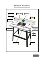
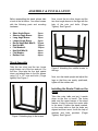
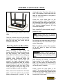
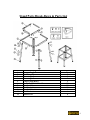
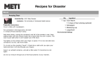
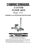
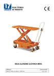
B2944 ROUTER TABLE WITH FENCE & STAND User Manual INDEX General Safety Instructions .................................................................... Specific Safety Instructions ................................................................... Features ................................................................................................... Physical Features .................................................................................... 3 4 5 6 Stand Assembly....................................................................................... 7 Installing the Router Table on the Stand .............................................. 7 Mounting the Router Base Plate in the Router Table ........................... 8 Stand Parts Breakdown & Parts List ..................................................... 9 Router Parts Breakdown & Parts List....................................................10 Fence Parts Breakdown & Parts List .....................................................11 Warranty...................................................................................................12 2 General Safety Instructions Extreme caution should be used when operating all power tools. Know your power tool, be familiar with its operation, read through the owner’s manual and practice safe usage procedure at all times. ¾ CONNECT your machine ONLY to the matched and specific power source. ¾ NEVER reach over the table when the tool is in operation. It is dangerous. ¾ ALWAYS wear safety glasses respirators, hearing protection and safety shoes, when operating your machine. ¾ ALWAYS keep blades, knives and bits sharpened and properly aligned. ¾ DO NOT wear loose clothing or jewelry when operating your machine. ¾ A safe environment is important. Keep the area free of dust, dirt and other debris in the immediate vicinity of your machine. ¾ DISCONNECT the power source when changing drill bits, hollow chisels, router bits, shaper heads, blades, knives or making other adjustments or repairs. ¾ ALWAYS keep all safety guards in place and ensure their proper function ¾ NEVER leave a tool unattended while it is in operation. ¾ BE ALERT! DO NOT use prescription or other drugs that may affect your ability or judgment to safely use your machine. ¾ ALWAYS use push sticks and feather boards to safely feed your work through the machine. ¾ ALWAYS make sure that any tools used for adjustments are removed before operating the machine. ¾ Always keep the bystanders safely away while the machine is in operation. 3 B2944-Router Table with Fence & Stand Specific Safety Instructions Like all power tools and machinery, proper safety and attention must be adhered to. There is danger associated with using any tool or machine so pay careful attention each and every time you use your tool. If you are not familiar with the operations of a router table, you should obtain the advice and/or instructions from a qualified professional. ¾ MAKE SURE the router has been installed securely before staring the machine, for safe operation method. ¾ NEVER perform any “Free Hand” operation. Do not use your hands to support or guide the work-piece. Always use toggle clamp to secure the work-piece for cutting. ¾ DO NOT jam or try and over push the work piece into the machine during operation. This may cause damage to the machine. Feed the work piece with a firm grasp, slowly and easily and hold the work-piece against the fence. ¾ MAKE SURE the spindle rotates in the correct direction. ¾ DO NOT wear jewelry or loose clothing while operating this machine. ¾ DO NOT let anyone stand in front of the machine while operation. ¾ SAFETY GLASSES & RESPIRATOR is highly recommended when working with this machine. Some saw dust can be harmful to your lungs; please take caution when using this machine. ¾ TECHNICAL DIFFICULTIES. Any problems you may run into should be carefully looked at with the power OFF and the machine unplugged from the power source. ¾ ALWAYS feed the work-piece to the router bit against the rotation direction. ¾ NEVER draw the work-piece back during the cutting operation. Stop the router bit before drawing back the work-piece. ¾ INSPECT your work pieces. Make sure that they are free of nails, staples, tacks, knots and other objects that may be harmful to your router bit. ¾ ALWAYS keep bits sharpened and clean. IMPORTANT: The safety instructions given above can not be complete because the environment in every shop is different. Always consider safety first as it applies to your individual working conditions. 4 ROUTER TABLE FEATURES MODEL B2944- Router Table with Fence & Stand As part of the growing line of Craftex woodworking equipment, we are proud to offer B2944 - Router Table. The Craftex name guarantees Craft Excellence. By following the instructions and procedures laid out in this owner’s manual, you will receive years of excellent service and satisfaction. The B2944 is a professional tool and like all power tools, proper care and safety procedures should be adhered to. TABLE TOP Size: 32”-Long, 24”-Wide & 1-3/8”-Thick Aluminum Miter Track: 32” Long Aluminum T-Track: 11-3/4” Long Table Insert: 9” x 12” FENCE Size: 18”-Long, 6”-High & 1”-Thick L-Aluminum: 4” x 4” x 33”-Long Dust Port: 2-1/2” to 3” Gaurd: Fluorescent Plastic Plate Aluminum Miter Track: 18”-Long Ruler Label: 18”-Long STAND Made of: Cast Iron Height: 34” Includes: 4 non-marring Rubber Feet 5 PHYSICAL FEATURES Aluminum Miter-Track Ruler Label Dust Port Guard Table Top Aluminum T-Track Table Insert Guide Pin Aluminum Miter-Track Rubber Feet 6 ASSEMBLY & INSTALLATION Before assembling the stand, please take a look at the list below. Your stand comes with the following parts and mounting hardware. • • • • • • • • • • Short Angle Brace: Shorter Angle Brace: Long Angle Brace: Longer Angle Brace: Round Head Bolt M8x12: Hex Nut M8: Flat Washer8: Hex Bolt M6x16: Flat Washer: Rubber Feet: Now, mount the two other longer and the two short angle braces to the legs with the help of the nuts and bolts, (Finger Tighten). See Figure-2 2-pcs 2-pcs 2-pcs 2-pcs 32-pcs 32-pcs 32-pcs 4-pcs 4-pcs 4-pcs Stand Assembly Take the two short and the two longer angle braces out of the box and put it on the floor. Now take the four legs upside down, and attach them to the four braces using 1/4" x 1/2" nuts and bolts. (Finger tighten) See Figure-1. Figure-2 Attaching the middle braces to the legs Now, turn the stand upright and adjust the legs so that they are evenly positioned, tighten all the screws well. Installing the Router Table on the Stand Figure-1 Attaching legs to the braces Take the router table and put it upside down on the floor or bench. The router table and the upper braces of the stand feature 4 holes to mount the router table to the stand. Position the stand inverted, on the router table so that the holes are aligned and then mount it with the help of washers and bolts provided, (Finger Tighten). See Figure-3 7 ASSEMBLY & INSTALLATION starting pin holes. The holes will be to the right of the opening. Again mark with the tape the front and center on the plate to serve as a reminder. Center the router base plate on the nearest concentric ridge. Then position the mounting holes along the radial lines. Keep the base plate in place with tape. (3 to 4 pieces arranged around the ring should be adequate). Next, clamp the 2 plates together using Cclamps or wood. Figure-3 Mounting the stand to the router table Take the 4 rubber feet out of the package and attach one on each leg. Now, turn the stand up right and your router table is installed on the stand. Mounting the Router Base Plate in Your Router Table When mounting a large router, the handles should fit in the same direction as the long opening. Your current router base plate will function as the drilling jig. However, you should determine the optimum router positioning before the base plate. Make sure to take into account the depth adjustment knobs, depth lock levers/knobs and the location of your switch. Place your router in proper inverted position under the table. Then mark with tape on the front edge of the router’s bed plate to verify the position. Then, remove the screws from the base plate. Locate the top/front of your base plate by observing the position of the Note: Spring clamps will not provide enough clamping force and could allow the parts to move out of place. Drill through the new base using a drill bit that matches the size of the holes in your router’s base plate. Note: If available, perform this operation on a drill press to keep the holes perpendicular. Important: A piece of wood should be clamped to the front of the router plate whole drilling to avoid splintering of the plate. After removing the clamps, countersink holes similar to the router’s own base plate. For best result, we recommend a single flute countersink at a slow speed and a drill press if available. Finally, mount the base plate to the router. If the screws that came with your router are not long enough, longer screws can be purchased at a hardware store or home center in your area. 8 Stand Parts Break-Down & Parts List NO 1 2 3 4 5 6 7 8 9 10 11 DESCRIPTION Longer Angle Brace Short Angle Brace Short Angle Brace Short Angle Brace Longer Angle Brace Round Head Bolt M8 x 12 Hex Nut M8 Flat Washer8 Hex Bolt M6 x 16 Flat Washer6 Rubber Feet QTY 4 2 2 2 2 32 32 32 4 4 4 9 Router Table Parts Break-Down & Parts List NO 1 2 3 4 5 6 7 QTY 1 1 11 4 2 4 1 PART Table Top Aluminum Miter Track Flat Head Tapping Screw Nut Aluminum T-Track Hex Socket Set Screw Insert + Guide Pin DESCRIPTION 32” x 24” x 1-3/8” Length 32” 4” x 1/2" M 1/4” x 1/2" Length 11-3/4” 6x6 9” x 12” 10 Fence Parts Break-Down & Parts List NO 1 2 3 4 5 6 7 8 9 10 11 12 13 14 15 QTY 1 1 2 1 2 4 2 20 2 1 6 6 2 2 2 PART L-Aluminum Adapter Pan-Head Machine Screw Dust Port Triangle Knob Aluminum-Miter Track Hex Bolt Flat Head Tapping Screw Fence Bit Cover Hex Bolt Knob Ruler Label Flat Washer Hex Bolt DESCRIPTION 4” x 4” x 33” 2-1/2” x 2” 3/16” x 2-1/4” 2-1/2” x 3” 1/4" Length 18” 1/4" x 3/4" 4# x 1/2" 18” x 6” x 1” Fluorescent Plastic Plate 5/16” x 1-1/2” 5/16” Length 18” 1/4" 1/4” x 1” 11 WARRANTY CRAFTEX 1 YEAR LIMITED WARRANTY Craftex warrants every product to be free from defects in materials and agrees to correct such defects where applicable. This warranty covers one year for parts and 90 days for labour (unless specified otherwise), to the original purchaser from the date of purchase but does not apply to malfunctions arising directly or indirectly from misuse, abuse, improper installation or assembly, negligence, accidents, repairs or alterations or lack of maintenance. Proof of purchase is necessary. All warranty claims are subject to inspection of such products or part thereof and Craftex reserves the right to inspect any returned item before a refund or replacement may be issued. This warranty shall not apply to consumable products such as blades, bits, belts, cutters, chisels, punches etceteras. Craftex shall in no event be liable for injuries, accidental or otherwise, death to persons or damage to property or for incidental contingent, special or consequential damages arising from the use of our products. RETURNS, REPAIRS AND REPLACEMENTS To return, repair, or replace a Craftex product, you must visit the appropriate Busy Bee Tools showroom or call 1-800-461-BUSY. Craftex is a brand of equipment that is exclusive to Busy Bee Tools. For replacement parts directly from Busy Bee Tools, for this machine, please call 1-800-461-BUSY (2879), and have your credit card and part number handy. • • • • • • • • • • • • All returned merchandise will be subject to a minimum charge of 15% for re-stocking and handling with the following qualifications. Returns must be pre-authorized by us in writing. We do not accept collect shipments. Items returned for warranty purposes must be insured and shipped pre-paid to the nearest warehouse Returns must be accompanied with a copy of your original invoice as proof of purchase. Returns must be in an un-used condition and shipped in their original packaging a letter explaining your reason for the return. Incurred shipping and handling charges are not refundable. Busy Bee will repair or replace the item at our discretion and subject to our inspection. Repaired or replaced items will be returned to you pre-paid by our choice of carriers. Busy Bee reserves the right to refuse reimbursement or repairs or replacement if a third party without our prior authorization has carried out repairs to the item. Repairs made by Busy Bee are warranted for 30 days on parts and labour. Any unforeseen repair charges will be reported to you for acceptance prior to making the repairs. The Busy Bee Parts & Service Departments are fully equipped to do repairs on all products purchased from us with the exception of some products that require the return to their authorized repair depots. A Busy Bee representative will provide you with the necessary information to have this done. For faster service it is advisable to contact the nearest Busy Bee location for parts availability prior to bringing your product in for repair. 12