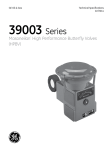
1
Top Quality Valve Actuators
Made in Sweden
Ref. 5.400B_UK - 04/2012 www.axel-larsson.se
USER
MANUAL
RC200
Instruction
Pneumatic actuator - AL 77-200
Manufacturer: Rotork, Sweden Original type: RC
Pneumatic Actuators
Type and Design
Manual Operation
DA = Double Acting. Actuator with pneumatic operation
in both directions.
SR = Spring Return. Actuator with spring return.
RC 210, 230, 250 and 270 have 1 piston.
RC 220, 240, 260, 265 and 280 have 2 pistons.
WARNING!
Operating Medium
If the operating medium is instrument air, it shall be dust
and oil-free. Accepted operating medium: Non-dangerous
fluids (group 2 according to directive 97/23/EC). The dew
point shall be equal to –20 °C or, at least, 10 °C below the
ambient temperature. The maximum particle size must not
exceed 40 μm. The exhaust air must pass through a filter
silencer before it is let out into the workshop.
The Application of the Scotch Yoke
Construction
RC actuators must only be used as actuators on
valves. Levers, racks and similar cannot be used to
transmit movement without protective equipment.
Pinch risk in the valve opening when test trimming
non-installed valves.
The actuator can be equipped with handwheel for manual
operation, RC-M1. Other methods on request.
WARNING!
All manual operations must be carried out with a
vented actuator.
The Scotch Yoke of the RC200 actuators has canted slots.
Thus the actuator can be given different function depending on how the pistons are mounted in the actuator. The
pistons are mounted according to Fig.1, page 2, or Fig.1a,
in order to achieve the following functions.
According to Fig.1:
DA-Actuator with adjustable closed valve position (clockwise end of travel).
SRF-Actuator with spring opening (counter clockwise
direction), adjustable “closed” valve position (clockwise
end of travel).
According to Fig.1a:
DAAO-Actuator with adjustable open valve position (counter clockwise end of travel).
SR-Actuator with spring closing (clockwise direction),
adjustable “open” valve position (counter clockwise end of
travel).
The possibility to turn the pistons can be used in several
ways in order to suit the actuators to the customer’s
requirements.
WARNING!
It is very risky to try to operate the actuator manually by
using the key grip on the driving shaft. The accumulated
energy inside the actuator may instantaneously be set
free.
Installation and Adjustment
All types of actuators can be mounted in various positions,
e.y. vertical or horizontal. When mounting on a valve,
ensure that the actuator shaft and the valve stem are
centered, and that a play of 0,5-1 mm exists between shaft
and driving bush depending on actuator size. Ensure
especially that actuator and driving bush are mounted
correctly in relation to eachother, considering that the
actuator shaft has an octagonal hole and that a faulty
mounting of 45° is possible. This naturally also applies to
direct mounting on a valve.The guide ring (37) can be
dismantled when not in use. After mounting, it may be
necessary to adjust the turning angle of the actuator.
Tightening torques for lock nuts on page 6.
As mentioned previously, the DA actuators can, as standard, be adjusted in ”closed” valve position and the SR
actuators in ”open” position. The adjustment occurs by
loosening the lock nut on the end plate, after which the set
screw is turned clockwise for reduced and anti-clockwise
for increased rotary motion. The adjustment degree is ±3°.
RC220, 240, 260 and 280 have two adjustment screws.
It is important that both screws are in contact with the
piston in question.
The actuator is supplied with an indicator on the driving
shaft. The indicator can be mounted in 2 optional positions
for different valve functions, mounting directions, etc.
www.remotecontrol.se
5.400B_UK - 1
Ref. 5.400B_UK - 04/2012 www.axel-larsson.se
USER MANUAL
Pneumatic actuator - AL 77-200
4
6
12
34
20
21
31
27
18
32
19
Manufacturer: Rotork, Sweden Original type: RC
Fig. 1a
33
16
1
2
3
5
14
10
Fig. 1
9
11
8
35
36
15
39
38
37
40
WARNING!
22
23
6
25
28
30
29
Dwg 007469
Service of RC210-280
Before dismantling, check that the compressed air and
possible power supply are disconnected.
Dismantling of SR unit, see instruction on page 5.
Dismantling of SR unit with manual operation unit
type M1, see instruction on page 4.
Exchange of Piston Sealings and
Support Elements
1.
2.
3.
4.
26
Please read the warning above!
Dismantle the actuator from the console.
Dismantle the end plates (5) or the spring houses (25).
Fasten the actuator shaft between soft jaws in a vice
and turn the actuator until the pistons reach the cylinder
end. Then place a few rods in the holes on the outside
of one piston. By pressing together and pulling these
rods simultaneously, the piston is dismantled from the
cylinder.
5. If the piston O-ring (12) is worn, it must be replaced.
6. Replace the support band (14) if it is worn.
7. Replace the support element (9) if it is worn.
8. Grease the cylinder surface with a grease according to
the lubrication list on page 6.
9. Fit piston/s correctly positioned, see “The Application of
the Scotch Yoke construction“.
10. Fit the end plate/s or spring pack/s and adjust the shaft
turning angle.
Exchange of Shaft Sealings and
Support Washers
The O-rings (18) and (38) and the support washers (33)
and (39) can easily be replaced as below.
1. Please read the warning on the left!
2. Dismantle the actuator from the console.
3. Dismantle the retaining rings (31) and (40) around the
shaft.
4. Dismantle the worn details.
5. Fit the new O-rings (18) and (38).
6. Fit new washers under the retaining rings.
7. Use a grease according to the lubrication list on page
6 when mounting.
8. Fit the new retaining rings.
9. Check that the retaining rings are tightly fitted
without play in their grooves.
Exchange of Shaft Bearings
The bearings (16) and (36) and also the support ring
(19) on the RC210-240 can easily be replaced when the
pistons and shaft sealings are dismantled as above. For
larger actuators, please contact the supplier.
5.400B_UK - 2
www.remotecontrol.se
Ref. 5.400B_UK - 04/2012 www.axel-larsson.se
USER MANUAL
Pneumatic actuator - AL 77-200
Manufacturer: Rotork, Sweden Original type: RC
Material Table for RC210-280
Part No
Number Number
DA
SR
Description
Material
Surface treatment
1
Adjusting screw1
1
-
2
Lock nut1
1
-
3
O-ring1,6
1
-
4
Screw
8-16
8-16
5
6
7
8
9
10
11
12
14
End plate with centre hole
O-ring6
Cylinder
Scotch Yoke
Support element1,6
Piston1
Roll pin, double2,3
O-ring1,6
Support band1,6
1
2
1
1
1
1
1
1
1
2
1
1
1
1
1
1
1
15
Driving shaft
1
1
Size 210–260: Stainless steel
Others: Steel
Size 210–260: Stainless steel
Others: Steel
Nitrile
Size 210–260: Stainless steel
Others: Steel
Aluminium
Nitrile
Aluminium
Steel
POM
Aluminium
Spring steel
Nitrile
Polymer material
Size 210–260: Stainless steel
Others: Steel
16
1
1
Polymer material
1
1
Aluminium
Powder coated
18
19
20
21
22
23
24
25
Bearing, upper
End plate without centre
hole4
O-ring, upper6
Support ring, upper
Piston pin1
Piston roller1
Spring guide1
Spring, external1
Spring, internal1,5
Spring housing1
Zinc plated
Zinc plated
Zinc plated
Powder coated
Anodized
Zinc plated, yellow
chromated
-
1
1
1
1
-
1
1
1
1
1
1
1
1
26
Pre-tensioning screw1
-
1
27
28
Indicator
O-ring1,6
1
-
1
1
29
Lock nut1
-
1
30
31
32
33
Marking washer1
Retaining ring, upper6
Middle washer6
Support washer, upper6
1
1
1
1
1
1
1
34
Sealing1
1
1
35
36
37
38
39
40
Support ring, lower
Bearing, lower
Guide ring
O-ring, lower6
Support washer, lower6
Retaining ring, lower6
1
1
1
1
1
1
1
1
1
1
1
1
Nitrile
Polymer rmaterial
Steel
Steel
Aluminium
Alloyed spring steel
Alloyed spring steel
Aluminium
Size 210–260: Stainless steel
Others: Steel
Polymer material
Nitrile
Size 210–260: Stainless steel
Others: Steel
Aluminium
Spring steel
Stainless steel
Polymer material, chemically resistant
Size 210–240: Stainless steel
Others: Nitrile
Polymer material
Polymer material
Polymer material
Nitrile
Polymer material, chemically resistant
Spring steel
Corrosion protected
Corrosion protected
Powder coated
Zinc plated
Zinc plated
Anodized
Corrosion protected
Corrosion protected
17
1
1) For actuator sizes 220, 240, 260 and 280: The double amount of details. 2) RC240 has triple roll pins. 3) RC270–280 have a slotted pin in steel.
4) Not in the picture! Do not exist for sizes 220, 240, 260 and 280. 5) Only for sizes 270 and 280, not in the picture. 6) Included in seal kit.
5.400B_UK - 3
Ref. 5.400B_UK - 04/2012 www.axel-larsson.se
USER MANUAL
Pneumatic actuator - AL 77-200
Converting to SR Actuators
Manufacturer: Rotork, Sweden Original type: RC
Fig. 2
All DA actuators can be changed into SR actuators by
adding spring conversion kits according to the following
instruction:
1. Please read the warning on page 2!
2. Dismantle the end plates. (The description is for
RC220, 240, 260 and 280 which have two pistons).
3. Dismantle the pistons. See text under ”Exchange of
piston sealings and support elements”.
4. Mount the pistons according to figure 1 on page 2.
5. Check that the spring is correctly pre-tensioned
according to table 1 and figure 2.
6. The spring guide (22) is centered towards the piston
with the aid of 2 pins.
7. The SR units on sizes 230–280 must be turned so that
one of the three support points lies between the
bosses on the piston (10).
8. Mount the SR unit when the pistons are in their innermost position.
9. Put the screws (4) in place. When tightening the
screws, the spring force is transmitted from the
tensioning screw (26) to these screws.
Tightening torques according to table on page 6.
10. The turning angle of the actuator is adjusted with the
tensioning screw (26).
Adjustment is made with screw (26).
Table 1
RC200-SR actuator
A
RC210-220
41
RC230-240
62
RC250-260
87
RC270-280
137
Instructions for Dismantling of RC200-SR Actuators
with Manual Operation Unit Type M1
Fig. 3
WARNING!
Do not remove the protective tube (50) and
handwheel from the spring housing as long as the
springs are tensioned. This procedure must be
followed for safe dismantling of pre-tensioned
spring housings.
1. The actuator must be pressureless.
2. Check that the springs can press the piston back into
its starting position according to figure 3.
The upper shaft journal must not be oblique.
3. Disconnect possible power supply.
4. Turn the handwheel so that the threaded stem (51)
moves toward the actuator until it stops and the yellow
marker (68) can just barely be seen in the plastic tube (49).
5. For sizes RC220, 240, 260 and 280 (i.e. actuators with
two pistons): adjust the tensioning screw (26) in the
opposite spring housing anti-clockwise until it lies
against the spring guide (22). Dismantle the spring
housing by loosening the screws (4).
6. For all sizes: then turn the handwheel until there is
resistance and the yellow marker (68) can be seen
within the ”AUTO” position.
7. Dismantle the spring housing of the manual override
by loosening the retaining screws (4) and turning the
handwheel several turns in the direction which gives
the least resistance.
Dismantling must be carried out in the above order with the
utmost care. In the case of the slightest uncertainty contact the supplier.
5.400B_UK - 4
Ref. 5.400B_UK - 04/2012 www.axel-larsson.se
USER MANUAL
Pneumatic actuator - AL 77-200
Manufacturer: Rotork, Sweden Original type: RC
Instructions for Dismantling of RC200-SR Actuators
RC 210, 230, 250 and 270
WARNING!
The procedure below must be
followed for safe dismantling of
pretensioned spring housings.
1. The actuator must be pressureless.
2. Check that the springs can press the
piston into starting position according
to figure 4.
3. Disconnect all possible power supply.
4. Loosen the lock nut (29).
5. Turn the tensioning screw (26) anticlockwise until it lies lightly against the
spring guide (22).
6. Dismantle the spring housing by
loosening the screws (4).
7. Dismantling must be carried out with
the utmost care. In the case of the
slightest uncertainty - contact the
supplier.
Fig. 4
WARNING!
RC 220, 240, 260 and 280
The procedure below must be
followed for safe dismantling of
pretensioned spring housings.
Fig. 5
5.400B_UK - 5
www.remotecontrol.se
1. The actuator must be pressureless.
2. Check that the springs can press the
piston into starting position according
to figure 5.
3. Disconnect all possible power supply.
4. Loosen the lock nuts (29).
5. Turn both spring tensioning screws (26)
clockwise until they lies lightly against
the spring guides (22).
6. Turn the left spring tensioning screw
(26) anti-clockwise until it lies lightly
against the spring guide (22) and
dismantle the left spring housing by
loosening the screws (4).
7. Dismantle the right spring housing in
the same manner as the left one.
8. Dismantling must be carried out with
the utmost care. In the case of the
slightest uncertainty - contact the
supplier.
Ref. 5.400B_UK - 04/2012 www.axel-larsson.se
USER MANUAL
Pneumatic actuator - AL 77-200
Tightening Torques for Screws and
Lock Nuts
Manufacturer: Rotork, Sweden Original type: RC
Tightening Torques
The actuators must be screwed onto the console with
the correct tightening torque in order
Actuator
to remain stable during operation.
Please use as long screws
Console
as possible without the
threads grounding.
Screw
(4)
Actuator
RC210-220
4
RC230-240
4
RC250-260
17
RC265
23
171
RC270-280 76
551
Lock nut DA
(2)
Lock nut SR
(29)
17
33
90
55
120
7
17
33
55
120
1) Tightening torque with Stainless steel screw. A2 70 quality.
”L” is the screw length
according to drawing.
Resistance class min. 8.8. Lightly oiled screws.
Tightening Torques in Nm
Actuator
RC210-220
RC210-220
RC230-240
RC230-240
RC250-260
RC250-260
RC265
RC270
RC270
RC280
RC280
RC280
DIN
flange
F05
F07
F07
F10
F10
F12
F12
F14
170x110
F12
F16
F25
Thread
M6
M8
M8
M10
M10
M12
M12
M16
M16
M12
M20
M16
L max
(mm)
11
14
14
17
17
21
21
25
25
25
32
25
8
8,8
-
Air Connections
10
9,2
21
21
-
12
23
23
40
40
-
Screw length (mm)
14
16
18
20
23
23
45
45
45
45
60
70
75
75
60
70
75
75
125 140 155
125 140 155
70
75
75
125 140 155
DA
DATP
24
185
185
75
280
185
28
330
-
32
360
-
Reversed direction
of rotation
Double Acting
CW
CCW
CCW
SR
CW
SRF
Single Acting
with Spring Return
Air CW rotation
Spring CCW rotation
Air CCW rotation
Spring CW rotation
Lubrication
Recommended Lubrication Grease
RC actuators are permanently lubricated and additional
lubrication is normally not required. However, for actuators
performing 100,000 operation cycles or more under very
heavy load, an oil mist lubriction is recommended.
Oil mist lubrication requires a mineral oil type ISO VG32
according to DIN 51524HLP for usage in temperature range
–10 to +70 °C. Oil mist lubricator must be set at lowest
possible value. Commenced oil mist lubrication must
continue.
If the actuator is equipped with pneumatic or electropneumatic positioner, oil mist must not be used.
Cylinder bore and
drive shaft
with shaft sealings
Grease
RC200 Standard
Klübersynth AR 34-402
RC200 high temp
Klübertemp HM 83-402
RC200 low temp
Klüber Isoflex Topas NCA 52
Piston roller (21) + bearing
All RC200
Grease
Cargo Red Grease
Oil mist lubrication and grease containing polyglycole, ester or
other aggressive additives shall be avoided.
5.400B_UK - 6
Ref. 5.400B_UK - 04/2012 www.axel-larsson.se
USER MANUAL
Pneumatic actuator - AL 77-200
Manufacturer: Rotork, Sweden Original type: RC
Material Table for RC210-280 M1
Part No
10M
22M
25M
41
42
43
43
44
45
46
Description
Piston M
Spring guide M
Spring housing M
Needle roller bearing RC250-280
O-ring
Needle roller bearing RC250-280
Slide bearing RC210-240
Cuff sealing
Key
Number
1
1
1
1
1
1
1
1
2
Handwheel
1
47
48
49
50
51A
51B
52
Set screw
O-ring
Tube, transparent
Protecting tube
Stem, DA (right threaded)
Stem, SR (left threaded)
Spring
1
1
1
1
2
1
1
53
54
55
56
57
58
59
61
62A
Locking hook
Tredo-sealing
Spacer, RC210-260
Screw, RC210-260
Spring Holder
Screw
O-ring, RC210-240
Screw
Stem nut, DA (right threaded)
1
2
1
1
1
1
1
2
1
62B
Stem nut, SR (leaft threaded)
1
Retaining ring, RC250-280
Handwheel bushing, RC250-280
Key
Screw, RC250-280
Label
Indication ring
1
2
1
1
1
1
63
64
65
66
67
68
Material
Aluminium
Aluminium
Aluminium
Ball bearing steel
Nitrile
Ball bearing steel
Bronze
Nitrile/Steel
Steel
Aluminium
RC280: Steel
Stainless steel
Nitrile
Acrylic Plastic
Aluminium
Steel
Steel
Stainless spring steel
Surface treatment
Powder coated
Zinc plated
Anodized
Powder coated
Anodized
-
Stainless steel
Nitrile/Steel
Stainless steel
Stainless steel
Stainless steel
Steel
Nitrile
Steel
RC210-240: Brass
RC250-280: Ductile iron
RC210-240: Brass
RC250-280: Ductile iron
Steel
Aluminium
Steel
Steel
Polymer material
Polymer material, yellow
Zinc plated
Zinc plated
Zinc plated
Zinc plated
Zinc plated
Corrosion protected
Anodized
Zinc plated
-
www.remotecontrol.se
5.400B_UK - 7
Ref. 5.400B_UK - 04/2012 www.axel-larsson.se
USER MANUAL
Pneumatic actuator - AL 77-200
Manufacturer: Rotork, Sweden Original type: RC
Function RC-M1
(51)
Neutral Position
With the stem (51) in Auto position, the piston (10M)
can move freely and the actuator can be
operated pneumatically. The picture shows a
double acting actuator, DA, in ”open” position or
a single acting actuator, SR, in ”closed” position.
(10M)
End Position Adjustments
M1 in Auto position works as an end position stop.
DA: Adjustment of closed valve position.
SR: Adjustment of open valve position.
Adjustment degree: +3° / –90° in relation to the end
position.
(46)
DA: The handwheel (46) is turned anti-clockwise.
The stem (51) and piston (10M) are pressed inwards.
The valve opens.
SR: The handwheel is turned clockwise. The stem
and piston are pressed inwards. The valve closes.
Manual Operation
DA: The handwheel is turned clockwise. The stem
and piston are drawn outwards. The valve closes.
SR: The handwheel is turned anti-clockwise. The
stem and piston are drawn outwards. The valve
opens.
The actuator (15) shaft is thus turned in the same direction as the handwheel.
When the actuator has been operated manually, a return to the Auto position must take place before remote operation
can be performed again.
On dismounting the manual operation housing (25M) , the actuator must first be ventilated, for SR actuators the stem
(51) must also be in Auto position.
Rotork Sweden AB
Box 80, Kontrollvägen 15
SE-791 22 Falun
Sweden
Tel +46 (0)23 587 00
Fax +46 (0)23 587 45
[email protected]
Head Office Axel Larsson Maskinaffär AB, Truckvägen
12, P.O. Box 805, SE-194 28 Upplands Väsby (Stockholm),
Sweden.
We reserve
the right to
- 8 90 E-mail: [email protected]
make changes without notice.
Telephone: +46 8 555 247 00 Fax:5.400B_UK
+46 8 555 247
www.remotecontrol.se
Design and specifications subject to change without prior notice.
Manual Operation