1
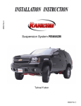
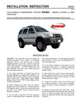
INSTALLATION INSTRUCTION 88051 Rev C For Rancho Suspension System RS6551: Chevrolet 2500 Suburban & 2500 Avalanche READ ALL INSTRUCTIONS THOROUGHLY FROM START TO FINISH BEFORE BEGINNING INSTALLATION IMPORTANT NOTES! WARNING: This suspension system will enhance the off-road performance of your vehicle. It will handle differently, both on and off-road, from a factory equipped passenger car or truck. Extreme care must be used to prevent loss of control or vehicle rollover during abrupt maneuvers. Failure to drive this vehicle safely may result in serious injury or death to the driver and passengers. ALWAYS WEAR your seat belts, REDUCE your speed, and AVOID sharp turns and other abrupt maneuvers. A. Before installing this system, have the vehicle’s alignment and frame checked by a certified technician. The alignment must be within factory specifications and the frame of the vehicle must be sound (no cracks, damage or corrosion). D. Each hardware kit in this system contains fasteners of high strength and specific size. Do not mix hardware kits or substitute a fastener of lesser strength. See bolt identification table on page 2. E. Compare the contents of this system with the parts list in these instructions. If any parts are missing, contact the Rancho Technical Department at 1-734-384-7804. F. Install all nuts and bolts with a flat washer. When both SAE (small OD) and USS (large OD) washers are used in a fastener assembly, place the USS washer against the slotted hole and the SAE washer against the round hole. B. Do not install a body lift kit with this suspension system or interchange Rancho components with parts from another manufacturer. Use the appropriate Rancho shock absorbers. G. Apply a drop of thread locking compound to all bolts during installation. CAUTION: Thread locking compound may irritate sensitive skin. Read warning label on container before use. C. Do not powdercoat or plate any of the components in this system. To change the appearance of components, automotive paint can be applied over the original coating. H. Unless otherwise specified, tighten all nuts and bolts to the standard torque specifications shown in the table below. USE A TORQUE WRENCH for accurate measurements. L. Although designed for 4wd vehicles, some Rancho suspension systems will fit 2wd applications. Refer to the application catalog or contact Rancho Technical Support at 1734-384-7804. If you are installing this system on a 2wd vehicle some of the steps in these instructions may not be applicable (4wd only). I. Some of the service procedures require the use of special tools designed for specific procedures. The following tools and supplies are recommended for proper installation of this system: 5 Chevrolet Service Manual Torsion Bar Unloading Tool J36202 Universal Steering Linkage Puller J24319 Ball Joint Separator J43631 Prevailing Torque Nuts (for steering linkage & front wheel drive shaft) Welder Die Grinder Drill motor Assorted Drills: 1/8" through 1" Torque Wrench (250 FT-LB capacity) 1/2” Drive Ratchet and Sockets Assorted Combination Wrenches Heavy Duty Jack Stands Wheel Chocks (wooden blocks) Hydraulic Floor Jack Center punch File Large "C" Clamps Reciprocating Saw (to modify frame and differential) Hammer Wire Brush (to clean bracket mounting surfaces) Black Enamel Paint Silicone Spray Lubricant Tape Measure Safety Glasses (wear safety glasses at all times) M. Welding is required when attaching box plate 176219. Prior to any welding, disconnect vehicle’s ground cable from battery. N. The required installation time for this system is approximately 6 to 7 hours. Check off the box ( 5 ) at the beginning of each step when you finish it. Then when you stop during the installation, it will be easier to find where you need to continue from. O. This suspension system was developed using the following tire & wheel combination: 285/75 R16 tire, 16 x 8 wheel with 4.5 inches of wheel backspacing. Before installing any other combination, consult your local tire and wheel specialist. P. Important information for the end user is contained in the consumer information pack. If you are installing this system for someone else, place the information pack on the driver’s seat. Please include the installation instructions when you finish. J. It is extremely important to replace torsion bars, CV flanges, and front drive shaft/pinion relationships as original. Be sure to mark left/right, front/rear, and indexing of mating parts before disassembly. A paint marker or light colored nail polish is handy for this. Q. Thank you for purchasing the best suspension system available. For the best-installed system, follow these instructions. If you do not have the tools or are unsure of your abilities, have this system installed by a certified technician. RANCHO SUSPENSION IS NOT RESPONSIBLE FOR DAMAGE OR FAILURE RESULTING FROM AN IMPROPER OR MODIFIED INSTALLATION… K. Suspension components that use rubber or urethane bushings should be tightened with the vehicle at normal ride height. This will prevent premature failure of the bushing and maintain ride comfort. STANDARD BOLT TORQUE & IDENTIFICATION Bolt Size 5/16 3/8 7/16 1/2 9/16 5/8 3/4 INCH SYSTEM Grade 5 15 FT-LB 30 FT-LB 45 FT-LB 65 FT-LB 95 FT-LB 135 FT-LB 185 FT-LB Grade 8 Bolt Size 20 FT-LB 35 FT-LB 60 FT-LB 90 FT-LB 130 FT-LB 175 FT-LB 280 FT-LB M6 M8 M10 M12 M14 M16 M18 2 METRIC SYSTEM Class 9.8 Class 10.9 5 FT-LB 18 FT-LB 32 FT-LB 55 FT-LB 85 FT-LB 130 FT-LB 170 FT-LB 9 FT-LB 23 FT-LB 45 FT-LB 75 FT-LB 120 FT-LB 165FT-LB 240FT-LB Class 12.9 12 FT-LB 27 FT-LB 50 FT-LB 90 FT-LB 145 FT-LB 210 FT-LB 290 FT-LB PARTS LIST P/N 15050 176138 176214 176215 176218 176219 176220 176221 176222 176226 176228 176236 7495 8051 860152 860175 860179 860180 420044 860182 860413 170014 DESCRIPTION Riser Block Aft Brace Bracket Knuckle, Left Knuckle, Right Subframe Box Plate (4wd only) Differential Support Bracket (4wd only) R. Axle Tube Drop Bracket (4wd only) Subframe Aft Brace Axle Spacer (4wd only) T Bar Drop Bracket Rear Bump Stop Spacer 9/16-18 x 2.57 x 11.0 U-bolt Riser Block Pin Kit .625 x .875 Pin U-bolt Hardware Kit 9/16-18 Nyloc Nut 9/16 Washer R. Axle Tube Hardware Kit (4wd only) 9/16-12 x 1.75 HHCS 9/16-12 Stover Nut 9/16 SAE Washer 9/16 USS Washer Frt. Differential Hardware Kit (4wd only) M10-1.50x60 HHCS 7/16-14 x 3.0 HHCS 7/16-14 Stover Nut Washer 7/16 SAE Washer End Link Hardware Kit .75x.156x9.5 Sleeve Retainer 3/8-16 x 14.0 HHCS 3/8-16 Nyloc Nut Rear Bump Stop Hardware Kit M10-1.50 x 30 HHCS 10mm Lock Washer 3/8 SAE Washer M8-1.25 x 10 HHCS Brake Line Bracket Kit Brake Line Bracket 5/16-18 x 1.25 HHCS 5/16-18 Stover Nut 5/16 SAE Washer P/N 860433 420041 520041 QTY. 2 2 1 1 1 1 1 1 2 2 2 2 4 1 2 1 8 8 1 2 2 2 2 1 5 1 1 5 2 1 2 8 2 2 1 2 2 2 1 1 1 1 1 2 860434 420042 448 520041 860435 603545 860436 860437 420043 552 860438 94180 780281 88051 94119 94177 3 DESCRIPTION Subframe Hardware Kit .75x.095x2.19 Sleeve Bushing 5/8-18 x 4.5 HHCS 5/8-18 x 5.5 HHCS 5/8-18 Stover Nut 5/8 SAE Washer 9/16-12 x 4.0 HHCS 9/16-12 Stover Nut 9/16 SAE Washer Thread Lock Aft Brace Hardware Kit .75 x .095 x 2.73 Sleeve Sleeve Bushing 1/2-13 x 2.5 HHCS 1/2-13 x 4.00 HHCS 1/2-13 Stover Nut 1/2 SAE Washer Skidplate Hardware Kit .625 x .375 x .5 Sleeve 3/8-16 x 1.0 HHTS 3/8-16 x 1.0 HHCS 3/8-16 x 1.75 HHCS 3/8-16 x 2.5 HHCS 3/8-16 Stover Nut 3/8 USS Washer 3/8 SAE Washer 3/8-16 x 2.50 HHCS Axle Spacer Hardware Kit (4wd only) M10-1.50 x 60 HHCS Lock Washer T Bar Crossmember Hardware Kit .75x.095 x 1.50 Sleeve Bushing 3/8-16 x 1.25 HHCS 3/8-16 Stover Nut 3/8 SAE Washer Brake Hose Bracket Hardware Kit M6-1.0 x 10 HHTS Information Pack Rancho Decal Instructions Consumer/Warranty Information Warning Sticker QTY. 1 1 2 2 2 4 8 1 1 2 2 1 4 2 8 2 4 6 12 1 1 2 1 1 1 2 2 2 1 1 12 12 1 2 4 8 8 16 1 2 1 1 1 1 1 7) Remove the 2 bolts holding the torsion bar crossmember to the frame rail brackets. See illustration #2. Remove the crossmember. FRONT SUSPENSION VEHICLE PREPARATION & TORSION BAR REMOVAL 8) Remove the torsion bars from the lower control arms. 1) Park the vehicle on a level surface. Set the parking brake and chock rear wheels. Measure and record the distance from the center of each wheel to the top of the fender opening. See illustration #1. WHEEL DRIVE SHAFT (HALF-SHAFT) REMOVAL 1) Remove the front shock absorbers. Remove the front bump stops. 2) Remove the sway bar end links. illustration #3. See Illustration #1 2) Raise the front of the vehicle and support the frame with jackstands. Remove the front wheels and set them aside. 3) Mark the torsion bars left and right. Make alignment marks on the torsion bars, the lower control arms, and the adjustment arms. 4) Install the GM torsion bar unloading tool (J36202) and increase the tension on the torsion bar. Remove the adjusting bolt and nut. See illustration #2. Illustration #3 3) (4wd only) Mark the differential output flange and the axle flange for installation reference. 4) (4wd only) Remove the cap, nut and washer from the hub. Remove the six bolts from the inboard flange. See illustration #4. Illustration #2 5) Relieve the tension on the torsion bar and remove the unloading tool. Slide the torsion bar forward and remove the adjustment arm. 6) Illustration #4 Repeat steps 4 and 5 for the other side. 4 5) (4wd only) Pull the half-shaft out of the hub and through the lower control arm opening. Be careful not to damage the drive shaft boots. 8) Remove the lower control arm pivot bolts. See illustration #6. Remove the lower control arm. 6) (4wd only) Repeat steps 3 through 5 for the other side. STEERING KNUCKLE & LOWER CONTROL ARM REMOVAL 1) Loosen the brake hose bracket on the brake hose (top of steering knuckle) by prying the bracket open with pliers. Remove the bolt and brake hose bracket from the steering knuckle. 2) Remove the brake caliper and its mounting bracket as an assembly. Hang the caliper assembly with wire or a tie wrap. 9) 3) Label the brake rotor left or right. Remove the brake rotor. FRONT DIFFERENTIAL REMOVAL (4WD ONLY) Illustration #6 Repeat steps 1 through 8 for the other side. 4) Remove the prevailing torque nut from the outer tie rod stud. Disconnect the tie rod end from the steering knuckle with a universal puller. 1) If applicable, remove the front differential skid plate and rear support bracket. 5) If applicable, disconnect the ABS connector and separate the cable from the upper control arm and the steering knuckle. 2) Reference mark the front drive shaft U-joint to the differential yoke. Remove the bolts and retainers from the yoke and slide the shaft rearward to disengage. Tape the bearing cap assemblies and secure the shaft out of the way. 6) Remove the nuts at the upper and lower ball joints. Disconnect the ball joints from the steering knuckle using separating tool J43631. Remove the steering knuckle and hub assembly. 3) Disconnect the electrical connector and the vent hose from the differential assembly. Cap vent to prevent contamination. 7) Remove the hub and bearing assembly mounting bolts. See illustration #5. Remove the hub and bearing assembly. Remove the splash shield and carefully remove the o-ring. 4) Remove the right axle tube nuts and the differential lower mounting bolt. See illustration #7. Illustration #7 Illustration #5 5 5) Cut off the differential lower frame mount from the driver side lower control arm. See illustration #8. Illustration #10 2) (4wd only) Install two bushings (520041) into differential support bracket 176220. Apply silicon lubricant and press sleeve 420041 through the installed bushings. See illustration #11. Illustration #8 6) Support the front differential assembly with a floor jack. Remove the upper mounting nut and bolt. Remove the differential assembly from the vehicle. 3) (4wd only) Remove the 5 case bolts from the front of the differential. See illustration #11. 7) Clean surface and weld box plate 176219 to inside of lower control arm frame bracket as shown in illustration #9. NOTE: After removing the bolts, oil may seep from the case. Do not stop installation at this point. 4) (4wd only) Attach bracket assembly 176220 to the front differential with the hardware from kit 860179. See illustration #11. Tighten the bolts to 35 ft lbs. Illustration #9 NOTE: Box plate 176219 does not have a protective coating and may develop surface rust. Remove rust before welding plate to lower control arm frame bracket. After installation, coat the plate and bracket with enamel paint or undercoating. Illustration #11 4) (4wd only) Attach the right axle tube bracket 176221 to the frame bracket with the original hardware. See illustration #12 for bracket orientation. Tighten nuts to 75 ft. lbs. FRONT DIFFERENTIAL & SUBFRAME INSTALLATION 1) (4wd only) Cut off the upper mount (1/4" from the case) from the front differential. See illustration #10. 5) (4wd only) Attach the front differential assembly to the subframe (176218) with the original hardware. Tighten nuts and bolts to 75 ft. lbs. CAUTION: When modifying the front differential, do not cut into the case itself. 6) Attach the OE bump stops to the subframe with the original hardware. 6 Illustration #12 7) (4wd only) Using a piece of thick plywood (1/2” minimum), support the subframe and differential assembly with a floor jack. 2) Connect left steering knuckle 176214 or 176216 to the lower and upper control arm ball joints. Tighten the nut on the lower ball joint stud to 74 ft. lbs., and the nut on the upper ball joint stud to 37 ft. lbs. 8) Raise the subframe up into the lower control arm frame brackets. Attach the subframe to the brackets with the original hardware. Tighten the subframe to bracket bolts to 107 ft. lbs. 3) Lubricate the original o-ring with wheel bearing grease. Install the o-ring and splash shield. See illustration #13. Be sure to align the ABS cable between the splash shield and steering knuckle. 9) (4wd only) Attach drop bracket 176221 (as shown in illustration #12) to the front differential axle tube with the 9/16" hardware from kit 860175. Tighten nuts and bolts to 75 ft. lb. NOTE: Verify that the left side of the front differential does not contact the rear frame bracket of the lower control arm. FAILURE TO PROVIDE CLEARANCE COULD CAUSE DAMAGE TO THE DIFFERENTIAL AND AXLE ASSEMBLY. 10) (4wd only) Reconnect the vent hose and electrical connector. Align marks and reconnect the front drive shaft to the differential. STEERING KNUCKLE & HALFSHAFT INSTALLATION Illustration #13 1) Loosely attach the left lower control arm to the subframe with the 5/8” hardware from kit 860433. NOTE: Replace o-ring if worn or damaged. 7 4) Apply thread lock to original bolts and attach the hub and bearing assembly to the left steering knuckle. Refer to illustration #13. Tighten the mounting bolts to 133 ft. lbs. 5) Loosen the tie rod end jam nut and thread the tie rod end inward 2.5 complete turns. Retighten the jam nut and attach the tie rod end to the new knuckle. Tighten the new prevailing torque nut to 33 ft. lbs. 6) (4wd only) Insert the wheel drive shaft (halfshaft) into the knuckle hub. Install the shaft washer and a new hub nut. Illustration #15 NOTE: Do not lubricate the wheel drive shaft splines or the knuckle hub with grease. 13) Repeat steps 1 through 11 for the other side. 7) (4wd only) Place axle spacer 176226 against the differential flange. Place the axle flange against the spacer. Align the flange marks and attach the axle to the differential with the hardware from kit 860436. Be sure to apply thread lock to the bolts. Tighten the flange bolts to 58 ft. lbs. 14) Attach the sway bar to the lower control arm with the new end link assemblies (from kit 860180) and the original bushings. See illustration #16. Insert the 3/8” x 14” bolt from the top. 8) Install the brake rotor. Reattach the front caliper with the original mounting bolts. Be sure to clean the bolt threads and apply thread lock. Tighten the caliper mounting bolts to 129 ft. lbs. 9) (4wd only) Place a drift or large screwdriver through the caliper to prevent the drive axle from turning. See illustration #14. Illustration #16 15) Install new Rancho shock absorbers. DIFFERENTIAL SKID PLATE INSTALLATION (OEM) Illustration #14 NOTE: Your vehicle may have a plastic or aluminum OE skid plate. Follow the instructions for the type of skid plate you are installing. 10) (4wd only) Tighten the axle hub nut to 155 ft. lbs. Remove the drift from the rotor. 1) Cut off the left side corners of the plastic skid plate and drill a new 3/8” hole. See illustration #17. 11) Reposition the brake hose clamp and place it over the two mounting holes on the back of the steering knuckle. Insert the tab into one hole and attach the clamp with the new self-tapping screw from hardware kit 860438. 2) Place skid plate (plastic or aluminum) against the subframe below the front differential. Attach the rear of the plastic skid plate to the subframe with the sleeve and 3/8” hardware from kit 860435. Attach the rear of the aluminum skid plate using one 3/8” x 2.5” bolt and the left side OE bushing of the skid plate. See illustrations #17 and #18. 12) If applicable, reconnect the ABS cable. Attach the ABS cable to the knuckle and upper control arm as shown in illustration #15. 8 3) Using the skid plate as a template, drill two 11/32” holes through the bottom of the subframe crossmember. 4) Attach the front of the skid plate to the subframe with the self-tapping screws from kit 860435. AFT BRACE ASSEMBLY & INSTALLATION 1) Lubricate two bushings (520041) and one sleeve (420042), from kit 860177, with a silicon spray. Press the bushings and sleeve into aft brace 176222 as shown in illustration 19. Illustration #17 2) Repeat step 1 to install the rest of the bushings and sleeves. 3) Using the hardware from kit 860177, loosely attach the angled end of each aft brace to the rear of the subframe (176218). NOTE: The angled end of the aft brace should direct the aft brace straight back. 4) Attach aft brace brackets (176138) to aft braces. See figure #19. Illustration #18 Illustration #19 9 4) Drill a 3/8” hole at each of the marked locations. Remove the bracket 5) Rotate aft brace assemblies up and secure the brackets to the transmission crossmember with cclamps. Remove the aft braces and mark the mounting hole locations on the bottom of the crossmember. CAUTION: Inspect the inside of the frame rail before drilling. Move any components that might become damaged. 6) Remove the brackets and drill a 1/2” hole through both sides of the crossmember at each location. Refer to illustration #19. 5) Repeat steps 2 through 4 for the other side. 6) Align marks and insert the left and right torsion bars into their respective lower control arms. Carefully slide the bars forward. Do not allow the torsion bars to contact the front axle boots. 7) Remove the OE crossmember bracket from the outside of the frame rail. Using a magnet or retrieving tool, insert spacer 448 into the crossmember and align with holes. Attach bracket 176138 to the crossmember with the hardware from kit 860434. See illustration #19. Reinstall crossmember bracket 7) Attach the torsion bar drop brackets to the crossmember with the original bolts. 8) Repeat the previous two steps for the other side. 8) Attach the crossmember assembly to the frame rails with the 3/8” hardware from kit 860437. Tighten all nuts and bolts to 35 ft. lbs. 9) Tighten the aft brace and bracket mounting bolts to 65 ft. lbs. 9) Slide a torsion bar rearward through the crossmember while holding the adjustment arm in proper position. Verify that the reference mark on the adjustment arm matches the mark on the end of the torsion bar. TORSION BAR & DROP BRACKET INSTALLATION 1) Insert two bushings and a sleeve from kit 860437 into each torsion bar drop bracket. 10) Install the torsion bar unloading tool and increase the tension on the torsion bar. 2) Place torsion bar drop bracket 176228 against the frame directly below the crossmember bracket. Secure the bracket to the frame with a C-clamp. See illustration #20. 11) Reinstall the retaining plate and adjusting bolt. Thread the adjusting bolt in until 1.5 inches of threads are exposed below the retaining plate. Remove the unloading tool. 12) Repeat steps 9 through 11 for other side. 13) Install front wheels and lower vehicle to ground. Tighten the lug nuts to 140 ft. lbs. 14) Tighten the lower control arm pivot bolts to 107 ft. lbs. REAR SUSPENSION RISER BLOCK INSTALLATION Illustration #20 NOTE: If positioned properly, the rear hole in drop bracket 176228 will align with an existing rivet on the bottom of the frame. 1) Chock front wheels. Raise the rear of the vehicle and support the frame with jack stands. Remove the rear wheels. 3) Mark and center punch the 2 smaller holes on the bottom of the frame and the 2 smaller holes on the outside of the frame. 2) Support the rear axle assembly with a floor jack. Remove both rear shock absorbers. Do not reuse OEM shock absorbers. 10 8) Reinstall the U-bolt spacer on top of the leaf spring. Attach the spring to the axle with the NEW Ubolts (7495), original anchor plate, and hardware from kit 860152. Snug the nuts down but do not tighten. 3) Remove the bracket holding the brake line junction block to the rear differential. 4) With the axle still being supported, remove the anchor plate, U-bolts, and spacer. See illustration #21. 9) Repeat steps 3 through 7 for the other side. 10) Cross tighten the U-bolt nuts evenly to 89 ft. lbs. 11) Install new Rancho shock absorbers. BRAKE LINE BRACKET INSTALLATION 1) Attach the new brake line bracket 170014 to the rear differential with the original bracket bolt. See illustration #23. Illustration #21 5) Carefully lower the rear axle and if applicable, remove the original riser block. Do not allow the axle to hang by any hoses or cables. 6) Insert a block pin from kit 8051 into the hole in the axle pad. Place the new riser block (15050) on the axle pad with the taller end of the block in the rear. See illustration #22. Illustration #23 2) Carefully reshape the brake line and attach the junction block to the top of bracket 170014. Use the 5/16” hardware from kit 860413. BUMP STOP SPACER INSTALLATION 1) Remove the nut holding the bump stop to the frame rail above the rear axle. Remove the bump stop. Illustration #22 2) Attach bump stop spacer 176236 to the frame rail with the hardware from kit 860182. 7) Raise the axle assembly until the riser block contacts the helper spring. Be sure to align the hole in the block with the head of the center bolt. 3) Cut off the tab from the original bump stop. Reduce the threaded stud to one inch. See illustration #24. 11 3) Ensure that the vehicle brake system operates correctly. If new brake hoses were installed, verify that each hose allows for full suspension movement. 4) Readjust headlamps. Have vehicle Aligned at a certified alignment facility. Recommended Alignment Specifications Caster (degrees): 4.5° ! 1.0° Camber (degrees): 0° - .3° Sum Toe In (degrees): .1° ! .2° Please retain this publication for future reference. See Important Note P. Illustration #24 4) Apply thread lock and attach the original bump stop to the installed spacer. See illustration #25. Illustration #25 5) Repeat steps 1 through 4 for the other side. 6) Install rear wheels and lower vehicle to ground. Tighten lug nuts to 140 ft. lbs. FINAL CHECKS & ADJUSTMENTS 1) Jounce suspension and move the vehicle to normalize ride height. Verify that the front spindle to fender height is 25.5" and that both sides are equal. If necessary, reinstall GM tool J 36202 and adjust the tension on the torsion bars to correct the height. 2) Turn the front wheels completely left then right. Verify adequate tire, wheel, and brake hose clearance. Inspect steering and suspension for tightness and proper operation. 12